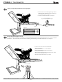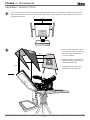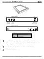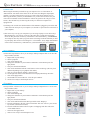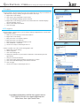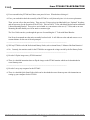
1
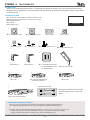
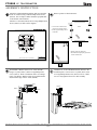
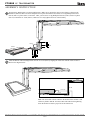
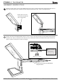
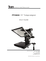
Features you need, Prices you want. PT3000 15” Teleprompter User Guide 3903 Stoney Brook Dr. Houston TX 77063 Tel: 1.713.272.8822 Fax: 1.713.995.4994 www.ikancorp.com [email protected] © 2009 ikan Corporation. All right reserved. PT3000 15” TELEPROMPTER INTRODUCTION Thank you for purchasing the ikan PT3000 15” Teleprompter. The PT3000 is extremely easy to use and will quickly become an integral part of your production kit. For more information on this and many other innovative ikan products, please visit our website: www.ikancorp.com. PACKAGE INCLUDES 15” LCD Monitor Kit (including AC Adapter and Power Cord) Prompter Hood Kit (includes 2 piece hood and 3 velcro strips) PrompterPro Software User Guide Teleprompter Parts: A B C 2 x 1/4-20 Receiving Nut 2 x 3/8-16 Receiving Nut E F 2 x 3/8-16 Screw I D 12 x T-Plate G 2 x 1/4-20 Screw J L-Bracket (S) Checked by H 32 x Phillips Head Screw(L) K L-Bracket (L) 8 x T-Slot Nut 8 x Phillips Head Screw(S) L 2 x 100mm Mounting Bracket (1 for Optional Battery Mount 1 for Monitor Mount) M O N 8” T-Slot P Prompter Glass Frame 8” T-Slot with Metal Bracket (Optional Tripod Mount) 10” T-Slot Additional Tool Needed: ** Not all parts needed for this teleprompter assembly, depends on your camera and tripod. 20” T-Slot with Metal Bracket CONDITIONS OF WARRANTY SERVICE • Free service for one year from the day of purchase if the problem is caused by manufacturing errors. • The components and maintenance service fee will be charged if the warranty period has expired. Free Service will not be Provided in the Following Situations: (* Even if the product is still within the warranty period.) • Damage caused by abuse or misuse, dismantling, or changes to the product not made by the company. • Damage caused by natural disaster, abnormal voltage, and environmental factors etc. 3903 Stoney Brook Dr. Houston TX 77063 | +1.713.272.8822 | www.ikancorp.com | [email protected] | © 2009 ikan Corporation. All right reserved. 1 of 10 PT3000 15” TELEPROMPTER ASSEMBLY INSTRUCTION 1 Attach the 100mm Mounting Bracket (Part K) to the back of the 15” monitor using 4 x Short Phillip’s head screws (Part H). The two flaps of Part K should be perpendicular to the monitor control buttons. Attach 4 x T-slot Nuts (Part D) and 4 x Long Phillips Head Screws (Part G) as shown on the diagram. 2 Remove protective film from Part-L. Part-L > Unscrew the 4 small screws that are pre-placed in Part L. > Remove glass holding tabs on both sides. Part-H Part-G Part-D Part-G Part-H > Peel the protective film away. > Re-install the teleprompter glass back into the metal frame. Part-K PT3000 Rear view of 15” monitor 3 4 Attach Short L-Bracket (Part I) to 8” T-slot (Part M) using 2 x T-plates (Part C) and 4 x Long Phillips head screws (Part G). Refer to illustration below for configuration. The Short L-Bracket’s (Part I) top half should be flush with the edge of the 8” T-slot (Part M). Attach the 20” T-slot with Metal Bracket (Part P) to the assembled parts. You will use 2 x T-plates (Part C) and 4 x Long Phillips Head screws (Part G) to do so. Make sure to evenly tighten all screws in this assembly. Part-I Part-G Part-C Part-G Part-P Part-M Part-C 3903 Stoney Brook Dr. Houston TX 77063 | +1.713.272.8822 | www.ikancorp.com | [email protected] | © 2009 ikan Corporation. All right reserved. 2 of 10 PT3000 15” TELEPROMPTER ASSEMBLY INSTRUCTION 5 Attach Long L-Bracket (Part J) to the assembled parts. Make sure to arrange the long section of Part J as shown in the illustration, otherwise there will not be adequate room to place the monitor. You will use 4 x Long Phillips head screws (Part G) and 2 x T-plates (Part C) to attach it. Then, you will use 4 x Long Phillips head screws (Part G) and 2 x T-plates (Part C) to attach the 10” T-slot (Part O). Make sure to evenly tighten all screws in the assembly. ikancorp.com Part-C Part-G Part-O Part-J Part-G 6 Slide the Monitor with mounting bracket onto the 10” T-slot (Part O), aligning the T-slot Nuts with the T-slots of Part O. Refer to the diagram below. ikancorp.com Side View Part-P ikancorp.com Part-M VGA Cable Part-O Note: The VGA cable will not connect to the monitor if the monitor is slid all the way flush to Part-M. You must connect the cable before tightening down the monitor to insure a proper fit for the connections. 3903 Stoney Brook Dr. Houston TX 77063 | +1.713.272.8822 | www.ikancorp.com | [email protected] | © 2009 ikan Corporation. All right reserved. 3 of 10 PT3000 15” TELEPROMPTER ASSEMBLY INSTRUCTION 7 Install 4 x T-plates (Part C) and 8 x Long Phillips Head screws (Part G) onto the Metal frame with Prompter Glass (Part L). Then, slide the Prompter Glass assembly onto the completed Teleprompter frame. Refer to the diagram below. Part-Q Part-L > Install 4 x Part-C on Part-L and secure with 8 x Part-G (Place the Part-C on the inner sides) Part-G Part-C 8 Attach your camera to the Metal Bracket on the 20” T-slot. To do so, first loosen each screw on the metal bracket and slide it off the T-slot. Then, use either the ¼-20 or the 3/8 screw to attach your camera to the metal bracket (Some cameras may require a washer or other spacer in order to fit snugly). Washer (Not included) ikancorp.com ** Some cameras may require an extra spacer, such as a washer, in order to fit snugly. Part-E or Part-F (depends on your camera) ikancorp.com > Loosen the screws and slide out the Metal Bracket through the channels 3903 Stoney Brook Dr. Houston TX 77063 | +1.713.272.8822 | www.ikancorp.com | [email protected] | © 2009 ikan Corporation. All right reserved. 4 of 10 PT3000 15” TELEPROMPTER 9a Attach your tripod skid plate directly to the teleprompter. > Slide in the Part-A or Part-B through the single channel of the bottom of the Part-P, and secure it with the screw on your tripod skid plate. See Figure 1. > Attach the assembled teleprompter to your tripod Part-A or Part-B (depends on your tripod skid plate) ikancorp.com Part-P Figure 1. Part-P (bottom view) 9b Attach your tripod skid plate to Part-N. For those who use a tripod that is rear loading (ie: your tripod skid plate slides into the tripod head from the rear), we have provided an optional piece , Part-N, will allow for more convenient attaching and detaching of the PT3000 Teleprompter on your tripod. > Loosen the screws and slide out the Metal Bracket through the channels > Install 2 x Part-A & Part-E or 2 x Part-B &Part-F > Slide in the Metal Bracket through the single channel of the bottom of the Part-P > Attach your tripod skid plate to the remaining Part-N (8” T-Slot) and secure them on your tripod head > Attach the assembled teleprompter to your tripod ikancorp.com Part-N (Metal Bracket) Part-N (8” T-Slot) your tripod 3903 Stoney Brook Dr. Houston TX 77063 | +1.713.272.8822 | www.ikancorp.com | [email protected] | © 2009 ikan Corporation. All right reserved. 5 of 10 PT3000 15” TELEPROMPTER ASSEMBLY INSTRUCTION 10 Use the Velcro strips to fit for three outer sides of the Prompter Glass Frame. Peel back the covering strips to expose the adhesive and then stick the Velcro to the sides of the frame. This will allow the Hood to connect when you place it on the assembled Teleprompter. velcro velcro velcro metal frame camera lens monitor 11 d oo h nt fro www .ikanc orp.co m hood back Step B A. Fasten the hood front to the edges of the glass frame, using the velcro you placed on in Step 10. Make sure it is securely fastened. B. Fasten hood back to the hood front. Make sure to drape curtain correctly around the bottom frame. Step A C. Tighten drawstring around lens or lens hood to prevent light leaks. velcro ikancorp.com your tripod 3903 Stoney Brook Dr. Houston TX 77063 | +1.713.272.8822 | www.ikancorp.com | [email protected] | © 2009 ikan Corporation. All right reserved. 6 of 10 Quick Start Guide PT3000 15” Monitor 15” Monitor Figure1 - Rear view 12V-24V 12V 4A VGA DC Power Connection VGA Connection DC IN DC 12V-24V Power Connection Figure2 - Front view FLIP < MENU > 5 4 3 2 1. 2. 3. 4. 5. 1 POWER > MENU < FLIP 1 Power switch (I = On, O = Off) While in MENU mode, toggle adjust setting Access to all monitor settings: Brightness, Contrast, etc While in MENU mode, toggle adjust setting Flip image horizontally Powering The Monitor. To do this, you have two options. a) You can plug the AC power adapter into the power input jack. See Figure 2. b) You can connect a pro battery using the optional accessories, PBK17-S or PBK17-A (Pro Battery Kit) and then plugging that plate into the DC-In connector. 2 Connecting PT3000 to your computer with VGA cable (not included in the PT3000 package). 3 3ft minimum for best viewing distance. 3903 Stoney Brook Dr. Houston TX 77063 | +1.713.272.8822 | www.ikancorp.com | [email protected] | © 2009 ikan Corporation. All right reserved. 7 of 10 Quick Start Guide / PT3000 (How to set-up your computer for the PT3000) Introduction When using the PT3000 you should set up you computer to be in “Clone Mode” or “Mirror Mode”. We do this so the talent can see the exact same thing the teleprompter operator is viewing. In this guide we will go over some of the most common ways of achieving this. Before you start you should make sure you have the last drivers for your video card. You should visit the manufactures website the get these. We will go over the Nvidia , ATI, and Intel way of achieving this as they are what most computers are equipped with. 1)Fist thing to do is make sure that the monitor of the PT3000 is plugged in powered on and connected to the VGA port of you computer. (It’s the blue 15 pin connector on the back of your computer) NVIDIA (figure 1) b. 2)The easiest way to set up your computer if you are using a laptop is to use the hot keys. Most laptops have a set of keys you press at the same time to toggle between display modes. In this particular case the key combination is FN and the F4 key. (see illustation) You will press these keys until you get the same exact image on the PT3000 that you have on your laptop. The mode we are looking for is “Clone Mode”. Every laptop manufacturer seems to have a different key combination so you should check your user’s manual. fn + d. f4 Nvidia (see figure 1) 3)If the above step did not work or you are using a desktop computer then we can do it the longer method. (Nvidia) a. Right-Click on your desktop b. Choose properties c. Click on the Settings tab d. Change the resolution of your monitor to 800x600 or 1024x768 and press the apply button. e. Now press the advanced button f. Click on the tab labeled with the word GeForce or the Nvidia logo. (this may look different depending on your graphics card model.) g. Click on “Nview Display Settings” on the left side. h. On the right side choose Clone from the Nview Display Mode drop down box. i. Click on the apply button. j. You should be in clone mode now. Close all open windows. k. You are now ready to start Prompter Pro V2. h. ATI (figure 2) b. ATI (see figure 2) 4)If step number 2 did not work or you are using a desktop computer then we can do it the longer method. (ATI) a. Right-Click on your desktop b. Choose properties c. Click on the Settings tab d. Change the resolution of your monitor to 800x600 or 1024x768 and press the apply button. e. Now press the advanced button f. Click on the Tab labeled with an ATI logo and the word “Displays” g. Press the red button to the left of the word monitor. This will “turn on” your second ary monitor (which is the PT3000) h. Press the small blue button with two squares overlapping each other. This is the “Clone Mode” button. i. Now Press the apply button. j. Your are now ready to start Prompter Pro V.2 8 of 10 d. h. Quick Start Guide / PT3000 (How to set-up your computer for the PT3000) ATI (see figure 3) ATI (figure 3) 5)If step number 2 did not work and you do not recognize the steps in step 4 but still have an ATI card and are using a desktop computer then follow these steps: a. Right-Click on the desktop b. Click on the “ATI CATALYST Control Center” c. Click on the Displays Manager option on the left d. Right-Click on the small grey picture of a monitor under the “Attached displays currently disabled” section e. Choose Clone Main with monitor f. Now click apply b. INTEL (see figure 4) 6)If step number 2 did not work or you are using a desktop computer then we can do it the longer method. (Intel) a. Make sure you are running at 1024x768 resolution b. Right-Click on the desktop c. Roll your mouse over Graphics Options d. Roll your mouse over Output To e. Roll your mouse over Intel Dual Display Clone f. Click on Monitor + Notebook g. You are now ready to start Prompter Pro V.2 7)There is another way to do it on the Intel graphics card: a. Right-Click on your desktop b. Choose properties c. Click on the Settings tab d. Change the resolution of your monitor to 800x600 or 1024x768 and press the apply button. e. Now press the advanced button f. Click on the “Intel Graphics Media Accelerator Driver” button g. Click on the Intel Dual Display Clone button on the left. h. Click on apply. i. You are now ready to start Prompter Pro V.2 d. intel (figure 4) d. c. f. e. (For Step 7) d. f. For additional help please call the ikan support team at 713-272-8822 or email us at [email protected] Office Hours: 9am - 6pm Central Time 9 of 10 g. ikan PT3000 TELEPROMPTER F.A.Q. Q: I have assembled my PT3000 and I have some parts left over. What do these belong to? A: First, you can double-check the assembly of the PT3000 to verify that each piece is in its correct placement. Then, you can refer to the parts listing. There are two (2) larger pieces included which are “Optional” bracketry and not necessary for the operation of the PT2100. These are the 8” T-Slot with Metal Bracket and an additional 100mm Mounting Bracket. These pieces are included as a convenience to the user (8” T-Slot) and as an extra Mounting Bracket should you wish to attach a counterweight. The User Guide can take you through the process of assembling the 8” T-slot with Metal Bracket. Part R can be mounted once the entire assembly has been built. It will slide on to the end and can serve as a counter-balance for the rear of the teleprompter. _______________________________________________________________________ Q: Will my PT3000 work with Professional Battery Packs, such as Anton Bauer, V-Mount of the Ikan Batteries? A: No. Currently, the monitors used for the PT3000 do not support the voltage carried by the Pro Battery Packs. _______________________________________________________________________ Q: How do I flip the image on my PT3000 monitor? A: There is a detailed instruction sheet to flip the image on the PT3000 monitor which can be downloaded at www.ikancorp.com. _______________________________________________________________________ Q: How do I set-up my computer for the PT3000? A: There is a detailed Quick Start Guide which can be downloaded at www.ikancorp.com with instructions on setting up your computer for the PT3000. 3903 Stoney Brook Dr. Houston TX 77063 | +1.713.272.8822 | www.ikancorp.com | [email protected] | © 2009 ikan Corporation. All right reserved. 10 of 10