1
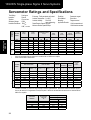
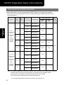
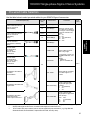
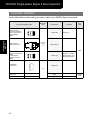
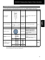
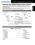
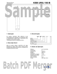
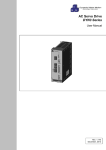
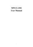
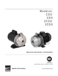
100/200V Single-phase Sigma II Servo Systems
Flat Series
SGMPH Servomotors - With Incremental / Absolute Encoder
Rated Output: 100W, 200W, 400W,
750W, 1500W
SGMPH Ratings & Specifications
SGMPH Speed/Torque Curves
SGMPH Dimensions
SGMPH Selection/Ordering Information
SGDH Ratings & Specifications
SGDH Dimensions
Page(s)
30
31
32
41
99
101
- 40
- 45
- 100
- 112
Design Features
1. Compact
! The length is about 1/2 of conventional motors
! Enhanced withstand load since motor output shaft bearing size is upgraded
! Up to 5000rpm maximum speed
2. Enhanced Environmental Resistance
! Water resistance (not including the shaft), IP67 standard
! Optional shaft seals available
! Reinforced lead-out cable access
3. Encoders (reduced wiring serial encoder)
! 13-bit (2,048ppr x 4) incremental encoder (standard)
! 16-bit (16,384ppr x 4) absolute encoder (option)
4. Application Emphasis
! Chip mounters
! PCB drilling machines
! Robots
! Conveyor
! Packaging
5. Certified International Standards
! UL, cUL recognized, (File #: E165827), CE compliance
27
SGMPH
Servomotors
For Additional Information
100/200V Single-phase Sigma II Servo Systems
Servomotor Ratings and Specifications
Applied
Voltage
Time Rating:
Insulation:
Vibration:
Withstand Voltage:
Insulation Resistance:
100Vac
200Vac
SGMPH
Servomotors
100Vac
200Vac
System Voltage
*
**
*
28
MOTORS:
SGMPH01A
02A
04A
08A
15A
01B
02B
04A**
Continuous
Class B
15µm or less
1500Vac
500VDC
10MΩ or more
Excitation:
Permanent magnet
Drive Method:
Direct drive
Mounting:
Flange-mounted
Applicable Encoder:
13-bit Incremental and
16-bit Absolute encoder
Enclosure: Totally-enclosed, self-cooled
Ambient Temperature: 0 to 40ºC
Ambient Humidity:
20 to 80%
(non-condensing)
Rated Rotation Speed: 3000rpm
Maximum Rotation Speed:5000rpm
Rated
Output
Rated
Torque
Instantaneous Peak
Torque
Continuous
Rated
Current*
Maximum
Peak
Current*
Rated
Angular
Acceleration
Rated
Power Rate
W (hp)
oz • in
N•m
oz • in
N•m
A rms
A rms
rad/s2
kW/s
100 (0.13)
200 (0.27)
400 (0.54)
750 (1.01)
1500 (2.01)
100 (0.13)
200 (0.27)
400 (0.54)
45.1
90.1
180
338
676
45.1
90.1
180
0.318
0.637
1.27
2.39
4.77
0.318
0.637
1.27
135
270
542
1010
2027
135
270
542
0.96
1.91
3.82
7.1
14.3
0.96
1.91
3.82
0.89
2.0
2.6
4.1
7.5
2.2
2.7
2.6
2.8
6.0
8.0
13.9
23.0
7.1
8.4
8.0
64800
33000
38500
11400
11900
64800
33000
38500
20.4
21.0
49.0
27.0
56.7
20.4
21.0
49.0
Holding Brake (at 20°C)
Coil
Rated
Capacity Resistance
Current
Allowable
Load
Inertia *
Values are calculated when the servomotor is combined with an SGDH servo amplifier.
When combined with an SGDH-04FE
Moment of Inertia
MOTORS
SGMPH-
Motor without Brake
oz • in • s2
× 10-3
Motor with Brake
KG • m2 × 10-4
oz • in • s2 × 10-3
KG • m2 × 10-4
W
Ω
A
KG • m2 × 10-4
01A
02A
04A
08A
15A
01B
02B
0.695
2.73
4.69
29.7
56.9
0.695
2.73
0.0491
0.193
0.331
2.10
4.02
0.0491
0.193
1.106
4.274
6.234
42.09
69.29
1.106
4.274
0.0781
0.302
0.44
2.975
4.895
0.0781
0.302
6
5
7.6
7.5
10
6
5
96
115
76
77
58
96
115
0.25
0.21
0.32
0.31
0.42
0.25
0.21
1.20
3.69
3.82
13.4
24.1
1.20
3.69
04A
4.69
0.331
6.234
0.44
7.6
76
0.32
3.82
Allowable load inertia (JL) shows the range requiring no exterior regenerative unit. When these values are exceeded, application may be restricted or a regenerative unit may be required. Values are calculated when the servomotor is combined with an
SGDH servo amplifier.
MOTORS
SGMPH-
Servomotor
Capacity
W
01'
02'
04A
08A
15A
100
200
400
750
1500
Holding Brake
Holding Torque
KG · cm
oz-in
69.5
5.0
139
10
279
20
514
37
1015
73
100/200V Single-phase Sigma II Servo Systems
Speed / Torque Curves
200V
SGMPH-02A
SGMPH-04A
5000
5000
4000
4000
4000
B
A
2000
3000
A
2000
B
1000
1000
1000
0
0.5
TORQUE (N m)
1
1.5
0
150
100
200
TORQUE (oz/in)
300
5000
4000
4000
SPEED (rpm)
SPEED (rpm)
1
B
A
2
3
4
0
200
400
TORQUE (oz/in)
600
SGMPH15A
5000
3000
A
2000
B
1000
1000
0
0
TORQUE (N m)
SGMPH-08A
2000
0
2
TORQUE (N m)
50
100
TORQUE (oz/in)
3000
B
A
2000
0
0
0 0.25 0.5 0.75 1.0
0
3000
SGMPH
Servomotors
3000
SPEED (rpm)
5000
SPEED (rpm)
SPEED (rpm)
SGMPH-01A
0
2
4
6
0
8
0
4
8
0
12
16
TORQUE (N m)
TORQUE (N m)
0
400
800
1200
TORQUE (oz/in)
800
1600
2400
TORQUE (oz/in)
100V
SGMPH-02B
SGMPH-04A*
5000
5000
5000
4000
4000
4000
SPEED (rpm)
SPEED (rpm)
SGMPH-01B
3000
A
2000
B
1000
3000
2000
A
3000
B
0
0
0 0.25 0.5 0.75 1.0
TORQUE (N m)
0
50
100
TORQUE (oz/in)
0.5
1
1.5
0
2
0
TORQUE (N m)
150
0
B
1000
1000
0
A
2000
100
200
TORQUE (oz/in)
1
2
3
4
TORQUE (N m)
300
0
200
400
TORQUE (oz/in)
600
A : CONTINUOUS DUTY ZONE
B : INTERMITTENT DUTY ZONE
*When combined with SGDH-04FE amplifier.
29
100/200V Single-phase Sigma II Servo Systems
Dimensions in inches (mm)
(1) 13-Bit Incremental or 16-Bit Absolute Encoder, w/o Brake
Note:
•
1. The keyway complies with JIS B1301-1976 (precision). A straight key is supplied.
2. Conforms to the IP67 enclosure, excluding the shaft (optional shaft seal available).
3. The quoted allowable radial load is the value at a position 5mm (0.2in) from the shaft end.
100W (0.13hp)
Encoder cable
UL20276 Φ0.24 (6)
11.81 (300) ±1.18 (30)
Encoder plug
SRUC 17GMRCN087
W
Motor Plug
U
T
Cross-section Y-Y
SRUC 06JMSCN236
Motor cable
0.71 (18)
SGMPH
Servomotors
Hexagonal nut
11.81 (300) ±1.18 (30)
Opposite Side width: 0.55 (14)
L
0.0016 (0.04) A
LR
LL
LC
LM
Φ0.0016 (Φ0.04) A
0.83 (21)
0.42 (10.5) 0.12 (3)
LG
ΦLA
ΦLB**
Y
Y
LC
QK
0.55
(14)
4 - ΦLZ
ΦS*
0.35 (9.0)
0.51
(13)
A
0.0008 (0.002)
Serial encoder
(absolute or incremental)
Key
Type SGMPH-
L
LL
LM
LR
LG
LC
ΦLA
ΦLZ
ΦS*
ΦLB**
01""E41D
01""E41D
3.43
(87)
2.44
(62)
1.67
(42.5)
0.98
(25)
0.24
(6)
2.36
(60)
2.76
(70)
0.21
(5.3)
0.315
(8)
1.97
(50)
QK
U
W
T
Output
W (hp)
0.55
(14)
0.071
(1.8)
0.12
(3)
0.12
(3)
100
(0.13)
Torque
in•lb
(N•m)
Time
Rating
Rated
Speed
(rpm)
Approx
Mass
lb (kg)
2.81
(0.318)
Continuous
3000
1.54
(0.7)
Allowable Allowable
Radial
Thrust
Load
Load
lb (N)
lb (N)
17.5
(78)
11.0
(49)
Note: The quoted allowable radial load is the value at a position 0.79in ( 20mm.) from the mounting surface.
†
Some motor dimensions vary for motors with the optional shaft seal: See p.38 for details.
Specified Tolerances
*Φ S
Dimension
Encoder Plug
1
2
3
11
10
12
13
17
5
16
15
14
4
6
9
8
7
SRUC 17GMRCN087
(Interconnectron)
**ΦLB
Unit
Diameter
Tolerance
Diameter
Tolerance
in
mm
0.3150
8.000
+0.0000-0.0004
+0.000 -0.009
1.9685
50.000
+0.0000 -0.0010
+0.000 -0.025
Incremental Terminal Specifications
Pin No.
Description
Color
1*
Battery —
2*
Battery * (3.6V)
—
3
Data +
Blue
4
Data−
Blue/White
5 - 7, 10 - 17
Free
—
8
+5V (Power Supply)
Red
9
0V (Power Supply)
Black
Connector Case
FG (Frame Ground)
Shield wire
*Note: Incremental Terminal pins number 1 and 2 are connectors
used for 16-bit absolute encoder option only.
Mating Connector: SPNA17HFRON16900E3
(Interconnectron)
30
Motor Plug
1
6
2
5
3
4
SRUC 06JMSCN236
(Interconnectron)
Motor Wiring Specifications
Pin
Number
Description
Color
1
2
3
6
Phase U
Phase V
Phase W
FG (Frame Ground)
Red
White
Blue
Green/Yellow
Mating Connector: SPNA06KFSDN169
(Interconnectron)
100/200V Single-phase Sigma II Servo Systems
200W (0.27hp), 400W (0.53hp)
Encoder cable
UL20276 Φ0.24 (6)
11.81 (300) ±1.18 (30)
U
Encoder plug
W
SRUC 17GMRCN087
Motor cable
Motor Plug
SRUC 06JMSCN236
T
Cross-section Y-Y
Hexagonal nut
Opposite side width: 0.55 (14)
LC
11.81 (300) ±1.18 (30)
LR
0.0016 (0.04)
0.33 (8.5) LG
0.35
(9.0)
Φ0.0016 (Φ0.04) A
0.12 (3)
4 - ΦLZ
QK
0.55
(14)
Y
LC
ΦLB**
0.51
(13)
0.83 (21)
A
SGMPH
Servomotors
0.28 (7)
0.71 (18)
maximum
L
LL
LM
ΦS*
•
Y
ΦLA
A
0.0008 (0.02)
Serial encoder
(absolute or incremental)
Key
Type SGMPH-
02""E41D
04""E41D
L
3.82
(97)
4.61
(117)
LL
LM
LR
2.64 1.89
(67) (48.1) 1.18
3.46 2.68 (30)
(87) (68.1)
LG
0.31
(8)
LC
3.15
(80)
ΦLA
ΦLZ
ΦS*
ΦLB**
3.54
(90)
0.28
(7)
0.551
(14)
2.76
(70)
QK
U
Voltage Output
W
T
0.63 0.12 0.20 0.20
(16) (3)
(5)
(5)
V
W (hp)
Torque
in•lb
(N•m)
200
200
(0.27)
400
(0.53)
5.64
(0.637)
11.2
(1.27)
Rated Approx
Speed Mass
(rpm) lb (kg)
Time
Rating
Continuous
3000
3.09
(1.4)
4.63
(2.1)
Allowable Allowable
Radial
Thrust
Load
Load
lb (N)
lb (N)
55.1
(245)
15.4
(68)
Note: The quoted allowable radial load is the value at a position 0.98in (25mm) from the mounting surface.
†Some motor dimensions vary for motors with the optional shaft seal: See p.38 for details.
Specified Tolerances
*Φ S
Dimension
**ΦLB
Unit
Diameter
Tolerance
Diameter
Tolerance
in
mm
0.5512
14.000
+0.0000-0.0004
+0.000 -0.011
2.7559
70.000
+0.0000 -0.0012
+0.000 -0.030
Interconnection Connector Specifications: See p.30.
31
100/200V Single-phase Sigma II Servo Systems
•
750W (1.01hp)
Encoder cable
UL20276 F0.24 (6)
U
11.81 (300) ±1.18 (30)
Encoder plug
W
SRUC 17GMRCN087
Motor Plug
MOTOR CABLE
T
SRUC 06JMSCN236
Cross-section Y - Y
11.81 (300) ±1.18 (30)
0.28
(7)
0.0016 (0.04)
LR
LC
1.50 (38)
Φ0.0016 (Φ0.04) A
SGMPH
Servomotors
0.14
(3.5)
QK
0.51 0.75
(13) (19)
Y
ΦS*
Y
LC
ΦLB**
0.35
(9.0)
A
1.1 (28)
maximum
L
LL
LM
0.41 (10.5)
LG
Hexagonal nut
Opposite side width: 0.67 (17)
ΦLA
4 - ΦLZ
A
0.0008 (0.002)
Serial encoder
(absolute or incremental)
Key
Type SGMPH-
L
LL
LM
LR
LG
LC
ΦLA
ΦLZ
ΦS*
ΦLB**
QK
U
W
T
Voltage Output
V
W (hp)
750
4.98 3.41 2.63 1.57 0.39 4.72 5.71 0.39 0.63 4.33 0.87 0.12 0.20 0.20
200
(1.01)
(126.5) (86.5) (66.7) (40) (10) (120) (145) (10) (16) (110) (22) (3) (5) (5)
Note: The quoted allowable radial load is the value at a position 1.38in (35mm) from the motor mounting surface.
†Some motor dimensions vary for motors with the optional shaft seal: See p.38 for details.
08""E41D
Torque
in•lb
(N•m)
Time
Rating
Rated Approx
Speed Mass lb
(rpm)
(kg)
21.1
(2.39)
Contin3000
uous
9.26
(4.2)
Specified Tolerances
*ΦS
Dimension
**ΦLB
Unit
Diameter
Tolerance
Diameter
Tolerance
in
mm
0.6299
16.000
+0.0000-0.0004
+0.000 -0.011
4.3307
110.000
+0.0000 -0.0014
+0.000 -0.035
Interconnection Connector .Specifications: See p.30.
32
Allowable Allowable
Radial
Thrust
Load
Load
lb (N)
lb (N)
88.1
(392)
33.0
(147)
100/200V Single-phase Sigma II Servo Systems
•
1500W (2.0hp)
Encoder cable
UL20276 Φ0.24 (6)
U
11.81 (300) ±1.18 (30)
W
Encoder plug
SRUC 17GMRCN087
Motor cable
T
Motor Plug
SRUC 06JMSCN020
Cross-section Y - Y
11.81 (300) ±1.18 (30)
LL
LR
LC
1.50 (38)
LM
0.41 (10.5)
LG
4 - ΦLZ
Φ0.0016 (Φ0.04) A
0.14 (3.5)
1.1 (28)
0.28
(7)
SGMPH
Servomotors
L
Hexagonal nut
Opposite side width: 0.67 (17)
A
maximum
0.0016 (0.04)
ΦLA
0.35
(9.0)
0.51 0.75
(13) (19)
QK
ΦS*
Y
LC
ΦLB**
Y
A
0.0008 (0.002)
Serial encoder
(absolute or incremental)
Key
ΦLA ΦLZ
ΦS*
ΦLB**
6.08 4.51 3.73 1.57 0.39 4.72 5.71 0.39
(154.5) (114.5) (94.7) (40) (10) (120) (145) (10)
0.75
(19)
4.33
(110)
Type SGMPH-
L
15""E41D
LL
LM
LR
LG
LC
QK
U
W
Voltage Output
V
W (hp)
T
0.87 0.14 0.24 0.24
(22) (3.5) (6)
(6)
Torque
in•lb
(N•m)
Time
Rating
42.1
(4.77)
Continuous
1500
(2.0)
200
Rated Approx
Speed Mass
(rpm) lb (kg)
3000
14.55
(6.6)
Allowable Allowable
Radial
Thrust
Load
Load
lb (N)
lb (N)
110
(490)
33.0
(147)
Note: The quoted allowable radial load is the value at a position 1.38in (35mm) from the motor mounting surface.
†
Some motor dimensions vary for motors with the optional shaft seal: See p.38 for details.
Specified Tolerances
*ΦS
Dimension
**ΦLB
Unit
Diameter
Tolerance
Diameter
Tolerance
in
mm
0.7480
19.000
+0.0000-0.0005
+0.000 -0.013
4.3307
110.000
+0.0000 -0.0014
+0.000 -0.035
Interconnection Connector Specifications
Encoder Plug
1
2
3
4
11
10
12
13
17
5
16
15
14
6
9
8
7
SRUC 17GMRCN087
(Interconnectron)
Incremental Terminal Specifications
Pin Number
Description
Color
1*
Battery —
2*
Battery * (3.6V)
—
3
Data +
Blue
4
Data−
Blue/White
5 - 7, 10 - 17
Free
—
8
+5V (Power Supply)
Red
9
0V (Power Supply)
Black
Connector Case FG (Frame Ground)
Shield wire
*Note: Incremental Terminal pins number 1 and 2 are connectors
used for 16-bit absolute encoder option only.
Motor Plug
1
6
2
5
3
4
SRUC 06JMSCN020
(Interconnectron)
Motor Wiring Specifications
Pin No.
Description
Color
1
2
3
6
Phase U
Phase V
Phase W
FG (Frame Ground)
Red
White
Blue
Green/Yellow
Mating Connector: SPNA06KFSDN169
(Interconnectron)
Mating Connector: SPNA17HFRON16900E3
(Interconnectron)
33
100/200V Single-phase Sigma II Servo Systems
(2) 13-Bit Incremental or 16-Bit Absolute Encoder, with Brake
Note:
•
1. The keyway complies with JIS B1301-1976 (precision). A straight key is supplied.
2. The electromagnetic brake is only to hold the load in position and cannot be used to stop the motor.
3. Conforms to the IP67 enclosure, excluding the shaft (optional shaft seal available).
100W (0.13hp)
11.81 (300) ±1.18 (30)
Encoder plug
Encoder cable
UL20276 Φ0.24 (6)
SRUC 17GMRCN087
W
U
Motor Plug
MOTOR cable
Φ0.0016 (Φ0.04) A
ΦLA
ΦLB**
LC
QK
Y
0.90
(23)
Y
Serial encoder
(Absolute or Incremental)
4 - ΦLZ
ΦS*
0.51
(13)
A
A
Magnetic brake: Non-excitation operation
DC power supply: 24V
0.0008 (0.002)
Key
LC
ΦLA
ΦLZ
ΦS*
ΦLB**
4.57 3.58 1.67 0.98 0.24 2.36
(116) (91) (42.5) (25) (6) (60)
2.76
(70)
0.22 0.315
(5.5) (8)
1.968
(50)
Type SGMPH-
L
01""E4CD
LL
LM
LR
LG
maximum.
0.0016 (0.04)
0.12 (3)
LG
0.35
(9.0)
LC
0.83 (21)
LR
0.71 (18)
SGMPH
Servomotors
L
LL
LM
0.41 (10.5)
Cross-section Y - Y
Hexagonal nut
Opposite side width: 0.67 (17)
11.81 (300) ±1.18 (30)
0.28 (7)
T
SRUC 06JMSCN236
QK
U
W
T
Voltage Output
(V)
W (hp)
Torque
in•lb
(N•m)
Time
Rating
Rated Approx
Speed Mass
(rpm) lb (kg)
100
(0.13)
2.81
(0.318)
Continuous
3000
0.55 0.071 0.12 0.12
(14) (1.8) (3)
(3)
200
1.5
(0.7)
Allowable
Radial
Load
lb (N)
Allowable
Thrust
Load
lb (N)
17.5
(78)
11.0
(49)
Note: The quoted allowable radial load is the value at a position 0.79in (20mm) from the motor mounting surface.
†Some motor dimensions vary for motors with the optional shaft seal: See p.38 for details.
Specified Tolerances
*Φ S
Dimension
**ΦLB
Unit
Diameter
Tolerance
Diameter
Tolerance
in
mm
0.3150
8.000
+0.0000-0.0004
+0.000 -0.009
1.9685
50.000
+0.0000 -0.0010
+0.000 -0.025
Interconnection Connector Specifications
Encoder Plug
1
2
3
4
11
10
12
13
17
15
14
5
16
6
9
8
7
SRUC 17GMRCN087
(Interconnectron)
Motor Plug
Incremental Terminal Specifications
Pin Number
Description
Color
1*
Battery 2*
Battery * (3.6V)
3
Data +
Blue
4
Data−
Blue/White
5 - 7, 10 - 17
Free
8
+5V (Power Supply)
Red
9
0V (Power Supply)
Black
Connector Case
FG (Frame Ground)
Shield wire
*Note: Incremental Terminal pins number 1 and 2 are connectors
used for 16-bit absolute encoder option only.
6
3
4
2
5
SRUC 06JMSCN236
(Interconnectron)
Mating Connector: SPNA17HFRON16900E3 (Interconnectron)
34
1
Motor Wiring Specifications
Pin Number
Description
Color
1
2
3
4
5
6
Phase U
Phase V
Phase W
Holding Brake
Holding Brake
FG (Frame Ground)
Red
White
Blue
Black
Black
Green/Yellow
Mating Connector: SPNA06KFSDN169
(Interconnectron)
100/200V Single-phase Sigma II Servo Systems
•
200W (0.27hp), 400W (0.53hp)
Encoder cable
UL20276 Φ0.24 (6)
11.81 (300) ±1.18 (30)
U
Encoder plug
W
SRUC 17GMRCN087
T
Motor cable
Motor Plug
SRUC 06JMSCN236
0.71 (18)
maximum
Φ0.0016 (Φ0.04) A
0.51
(13)
0.90
(23)
SGMPH
Servomotors
0.35
(9.0)
HEXAGONAL NUT
Opposite side width: 0.67 (17)
0.0016 (0.04) A
LC
0.83 (21)
11.81 (300) ±1.18 (30)
L
LR
LL
LM
LG
0.12 (3)
0.28 (7)
0.33 (8.5)
Cross-section Y-Y
QK
Serial encoder
(Absolute or Incremental)
ΦLA
ΦS*
Y
LC
ΦLB**
Y
ΦLZ
A
Magnetic brake: Non-excitation operation
DC power supply: 24V
0.0008 (0.002)
Key
Type SGMPH-
02""E4CD
04""E4CD
L
LL
LM
LR
LG
LC
ΦLA ΦLZ
5.06
3.88
1.89
(128.5) (98.5) (48.1) 1.18 0.31 3.15 3.54
5.85
4.67
2.68 (30) (8) (80) (90)
(148.5) (118.5) (68.1)
ΦS*
ΦLB**
0.28 0.551
(7)
(14)
2.756
(70)
QK
U
W
T
0.63 0.12 0.20 0.20
(16) (3) (5) (5)
Voltage Output
V
W (hp)
Torque
in•lb
( N•m)
Time
Rating
Rated
Speed
(rpm)
Approx
Mass
lb (kg)
200
(0.27)
400
(0.53)
5.64
(0.637)
11.2
(1.27)
Continuous
3000
4.2
(1.9)
5.7
(2.6)
200
400
Allowable Allowable
Radial
Thrust
Load lb
Load
(N)
lb (N)
55.1
(245)
15.29
(68)
Note: The quoted allowable radial load is the value at a position 0.98in (25mm) from the motor mounting surface.
†Some motor dimensions vary for motors with the optional shaft seal: See p.38 for details.
Specified Tolerances
*Φ S
Dimension
**ΦLB
Unit
Diameter
Tolerance
Diameter
Tolerance
in
mm
0.5512
14.000
+0.0000-0.0004
+0.000 -0.011
2.7559
70.000
+0.0000 -0.0012
+0.000 -0.030
Interconnection Connector Specifications: See p.33.
35
100/200V Single-phase Sigma II Servo Systems
750W (1.01hp)
Encoder cable
UL20276 Φ0.24 (6)
11.81 (300) ±1.18 (30)
Encoder plug
U
SRUC 17GMRCN087
W
•
Motor cable
Motor Plug
SRUC 06JMSCN236
T
11.81 (300) ±1.18 (30)
0.0016 (0.04) A
1.5 (38)
Φ0.0016 (Φ0.04)
0.14 (3.5)
A
4 - ΦLZ
QK
0.51
(13)
1.0
(25.5)
Y
ΦS*
Y
ΦLC
ΦLB**
SGMPH
Servomotors
0.35
(9.0)
LR
1.1 (28)
0.28 (7)
Hexagonal nut
Opposite side width: 0.55 (14)
LC
maximum.
L
LL
LM
0.41 (10.5)
LG
Cross-section Y - Y
ΦLA
A
Serial encoder
(Absolute or Incremental)
Magnetic brake: Non-excitation operation
DC power supply: 24V
0.0008 (0.002)
Key
Type SGMPH-
08""E4CD
L
LL
LM
LR
LG
LC
ΦLA
ΦLZ ΦS* ΦLB**
6.42 4.84 2.63 1.57 0.39 4.72 5.71 0.39
(163) (123) (66.7) (40) (10) (120) (145) (10)
0.63
(16)
4.33
(110)
QK
U
W
T
0.87 0.12 0.20 0.20
(22) (3)
(5)
(5)
Voltage
V
Output
W (hp)
Torque
in•lb
(N•m)
Time
Rating
Rated
Speed
(rpm)
Approx
Mass
lb (kg)
200
750
(1.01)
21.15
(2.39)
Continuous
3000
12.6
(5.7)
Note: The quoted allowable radial load is the value at a position 1.38in (35mm) from the motor mounting surface.
†
Some motor dimensions vary for motors with the optional shaft seal: See p.38 for details.
Specified Tolerances
*Φ S
Dimension
**ΦLB
Unit
Diameter
Tolerance
Diameter
Tolerance
in
mm
0.6299
16.000
+0.0000-0.0004
+0.000 -0.011
4.3307
110.000
+0.0000 -0.0014
+0.000 -0.035
Interconnection Connector Specifications:
See p.33.
.
36
Allowable Allowable
Radial
Thrust
Load lb
Load
(N)
lb (N)
88.1
(392)
33.0
(147)
100/200V Single-phase Sigma II Servo Systems
•
1500W (2.0hp)
Encoder cable
UL20276 Φ0.24 (6)
11.81 (300) ±1.18 (30)
U
Encoder plug
W
SRUC 17GMRCN087
T
Motor Plug
Motor cable
SRUC 06JMSCN020
Cross-section Y - Y
11.81 (300) ±1.18 (30)
0.0016 (0.04)
LR
LC
1.50 (38)
LG
0.41 (10.5)
0.14 (3.5)
Φ0.0016 (Φ0.04) A
QK
1.00
(25.5)
ΦLB**
ΦS*
Y
LC
0.35
(9.0) 0.51
(13)
1.1 (28)
Maximum
0.28 1.30 (33)
(7)
Hexagonal nut
Opposite side width: 0.55 (14)
A
SGMPH
Servomotors
L
LL
LM
Y
Serial encoder
(Absolute or Incremental)
A
Magnetic brake: Non-excitation operation
DC power supply: 24V
0.0008 (0.002)
Key
Type SGMPH-
L
LL
15""E4CD
7.40
(188)
5.83
(148)
ΦLA
ΦLZ
ΦS*
ΦLB**
3.73 1.57 0.39 4.72 5.71
(94.7) (40) (10) (120) (145)
0.39
(10)
0.75
(19)
4.33
(110)
LM
LR
LG
LC
QK
U
W
T
0.87 0.14 0.24 0.24
(22) (3.5) (6)
(6)
Voltage Output
V
W (hp)
Torque
in•lb
( N•m)
Time
Rating
Rated Approx
Speed Mass
(rpm) lb (kg)
1500
(2.02)
42.1
(4.77)
Continuous
3000
200
17.9
(8.1)
Allowable Allowable
Radial
Thrust
Load
Load
lb (N)
lb (N)
110
(490)
33.0
(147)
Note: The quoted allowable radial load is the value at a position 1.38in (35mm) from the motor mounting surface.
†Some motor dimensions vary for motors with the optional shaft seal: See p.38 for details.
Specified Tolerances
*ΦS
Dimension
**ΦLB
Unit
Diameter
Tolerance
Diameter
Tolerance
in
mm
0.7480
19.000
+0.0000-0.0005
+0.000 -0.013
2.7559
70.000
+0.0000 -0.0014
+0.000 -0.035
Interconnection Connector Specifications
Encoder Plug
1
2
3
4
11
10
12
13
17
15
14
5
16
6
9
8
7
SRUC 17GMRCN087
(Interconnectron)
Incremental Terminal Specifications
Pin Number
Description
Color
1*
Battery —
2*
Battery * (3.6V)
—
3
Data +
Blue
4
Data −
Blue/White
5 - 7, 10 - 17
Free
—
8
+5V (Power Supply)
Red
9
0V (Power Supply)
Black
Connector Case FG (Frame Ground) Shield wire
*Note: Incremental Terminal pins number 1 and 2 are
connectors used for 16-bit absolute encoder option
only.
Motor Plug
1
6
2
5
3
4
SRUC 06JMSCN020
(Interconnectron)
Motor Wiring Specifications
Pin
No.
Description
Color
1
2
3
4
5
6
Phase U
Phase V
Phase W
Holding Brake
Holding Brake
FG (Frame Ground)
Red
White
Blue
Black
Black
Green/Yellow
Mating Connector: SPNA06KFSDN169
(Interconnectron
Mating Connector: SPNA17HFRON16900E3
(Interconnectron)
37
100/200V Single-phase Sigma II Servo Systems
Dimension Modifications for Motors with Optional Shaft Seal
LR
LE
LD
ΦLB
LP
ΦS
QK
SGMPH
Servomotors
Shaft Seal
Type SGMPH01
02
04
08
15
QK
0.55 (14)
ΦLB*
ΦS*
1.97 (50)
0.31 (8)
LE
0.64 (16)
2.76 (70)
0.55 (14)
0.87 (22)
4.33 (110)
0.63 (16)
0.75 (19)
0.12 (3)
0.14 (3.5)
ΦLP
LR
0.98 (25)
LD
0.28 (7)
1.54 (39)
1.18 (30)
0.39 (10)
1.93 (49)
1.57 (40)
0.41 (10.5)
3.03 (77)
*Refer to the following table for tolerances for diameters LB and S.
Specified Tolerances
* ΦS
Dimension
Unit
in
mm
**ΦLB
Diameter
Tolerance
Diameter
Tolerance
0.3150
0.5512
0.6299
0.7480
8.000
14.000
16.000
19.000
+0.0000-0.0004
+0.0000-0.0004
+0.0000-0.0004
+0.0000-0.0005
+0.000 -0.009
+0.000 -0.011
+0.000 -0.011
+0.000 -0.013
1.9685
2.7559
4.3307
+0.0000 -0.0010
+0.0000 -0.0014
+0.0000 -0.0014
50.000
70.000
110.000
+0.000 -0.025
+0.000 -0.035
+0.000 -0.035
Torque Reduction Factor for SGMPH motors equipped with a shaft seal:
Servo Motor Model
Torque Reduction
Factor
01
02
04
08
15
90%
90%
95%
95%
95%
For Example: The SGMPH-01 continuous and peak torque rating should be reduced to
90% of the listed catalog specification.
To specify a motor with a shaft seal, refer to the motor part number explanation on the
following page.
38
100/200V Single-phase Sigma II Servo Systems
Selecting Your SGMPH Sigma II Servo System
First, select the Sigma II servomotor suited for your application using SigmaSize: the Yaskawa
servomotor sizing software, available at no charge. (Request SigmaSize software via e-mail, at:
[email protected]).
Use the diagram below to locate and identify the components of your system. Each item is lettercoded and cross-referenced in the option tables on the following pages.
System Configuration
Digital Operator (E)
Optional Holding Brake
5CN
Shaft Keyway
For Monitor (D)
SGDH Servo
Amplifier
(B)
Connector
Encoder (D)
Shaft Seal
Encoder side
Connector (D)
SGMPH
Servomotors
3CN
Peripheral
Signal
Cable (E)
SGMPH
Servomotor
(A)
Motor side
Connector (D)
2CN
1CN
Encoder Cable (C)
Motor Cable (C)
I/O Signal
Connector
(D)
Specify a technical manual, if it is needed, on your
servo system purchase order:
Regenerative Unit (E)
Sigma II Series Servo System User’s Manual: YEA-SIA-S800-32.2
(Manual is provided at no charge with a purchase order,
but it must be requested).
Model Number Designation
SGMPH - 01 A A E 4 1D
Sigma Servomotor Type
Rated Output
01: 100W (0.13hp)
02: 200W (0.25hp)
04: 400W (0.5hp)
08: 750W (1hp)
15: 1.5kW (2hp)
Power Supply
A: 200V UL Recognized
B: 100V UL Recognized
Accessories
1D: Standard
CD: Standard with 24VDC Holding Brake
SD: Standard with Shaft Seal
ED: Standard with Brake & Shaft Seal
Shaft Specifications
4: Straight Shaft with Keyway
Revision Level
Encoder Specifications
A: 13-Bit (2048 x 4) Incremental Encoder
1: 16-Bit (16,384 x 4) Absolute Encoder
39
100/200V Single-phase Sigma II Servo Systems
Servomotor & Amplifier Selection
Use the table below to select the appropriate SGMPH Sigma II servomotor and amplifier.
(Refer to the motor model # designation on the previous page specifying the available modification to motor
construction/features.)
Description
Peak
Torque
(oz • in)
135
SGMPH
Servomotors
200V
13-Bit Incremental
Encoder
Straight Shaft with
Keyway
270
542
Rated
Torque
(oz • in)
1010
2027
100V, 1-Phase
135
270
0.917
SGMPH-01AAE41D
1.46
SGMPH-01AAE4CD
2.96
SGMPH-02AAE41D
4.35
SGMPH-02AAE4CD
4.92
SGMPH-04AAE41D
6.31
SGMPH-04AAE4CD
29.9
SGMPH-08AAE41D
181
338
35.7
SGMPH-08AAE4CD
57.1
SGMPH-15AAE41D
67.8
SGMPH-15AAE4CD
0.917
SGMPH-01BAE41D
676
45.1
1.46
SGMPH-01BAE4CD
2.96
SGMPH-02BAE41D
90.1
5000rpm
Pre-wired with
Heavy Duty
Connectors
542
Motor MODEL # (A)
90.1
13-Bit Incremental
Encoder
Straight Shaft with
Keyway
Amplifier MODEL # (B)*
45.1
5000rpm
Pre-wired with
Heavy Duty
Connectors
Motor Inertia
(oz • in • s2x10-3)
4.35
SGMPH-02BAE4CD
4.92
SGMPH-04AAE41D
181
6.31
1-Phase
SGDH-
3-Phase
SGDH-
01AE
—
02AE
—
04AE
—
08AE-S
08AE
Motor &
Amplifier
Item Class
Stock
15AE-S
15AE
01BE
—
02BE
—
04FE
—
SGMPH-04AAE4CD
Notes: 24VDC brakes for SGMPH Sigma II servomotors are standard. Contact a local source for 24VDC power supplies. Motor power
and encoder cables are factory pre-wired with approximately 13” lead length with heavy duty mating connectors.
Use the tables on the following page to specify mating connectors and/or various cable lengths.
For technical information, request Yaskawa manual number YEA-SIA-S800-32.2.
* For more detailed SGDH amplifier specifications and dimensions, refer to pages 99 to 112.
40
100/200V Single-phase Sigma II Servo Systems
Pre-wired Cable Selection
Use the table below to select pre-wired cables for your SGMPH Sigma II servomotor.
Power Cable with Interconnectron Connectors
(without Brake)
Power Cable with Interconnectron Connectors
(with Brake)
(IP67)
Motor Size
(kW)
Part Number*
0.1, 0.2,
0.4, 0.8
B4ICE-''(A)
1.5
B5ICE-''(A)
0.1, 0.2,
0.4, 0.8
B4IBCE-''(A)
1.5
B5IBCE-''(A)
Encoder Cable with Interconnectron Connector
(incremental or absolute)
(IP67)
A1ICE-''(A)
Encoder Cable
(for applications
up to 20m)
Only for Solder
Connections
FR-RMCT-SB
Encoder Cable
(for applications
from >20 to <50m)
Only for Solder
Connections
UL20276-SB
Comments
Item
Class
These UL and CE compliant cables are available in
five lengths. Use two digits
in the part number’s last
place:
03: 3m
05: 5m
10: 10m (standard)
15: 15m
20: 20m
SGMPH
Servomotors
Cable Description (C)
These cables are available in any length.
For example, to order one
FR-RMCT-SB cable, 16m
long,
specify:
quantity:16
part no.: FR-RMCT-SB
Stock**
All
Input/Output 1CN Cable &
Transition
Terminal Block
Input/Output 1CN Cable with
Pigtail Leads
Input/Output 1CN Cable
Cable with Female
D-Sub output Connector***
*
**
***
JUSP-TA50P
35mm DIN rail mountable;
the cable length is 0.5
meters.
JZSP-CKI01-'(A)
Use the following key to
specify required cable
length (last digit of part
number):
1: 1m (standard)
2: 2m
3: 3m
Use the following key to
specify required cable
length (last two digits of the
part number):
JZSP-CKI0D-''
D50:
01:
02:
03:
0.5m
1m (standard)
2m
3m
The “(A)” at the end of the cable part number is the revision level. Revision level may be changed prior to catalog reprinting.
Standard cable lengths are Stock items; non-standard cable lengths are Limited Stock items.
50 Pin Female D-Sub output connector mates to customer supplied third party terminal block. (e.g., Wago #289-449,
Weidmuller #919658, Phoenix #2283647, Amphenol/Sine #20-51039, and many others)
41
100/200V Single-phase Sigma II Servo Systems
Connector Selection
Use the table below to select mating connectors or kits for your SGMPH Sigma II servomotor.
Connector Description (D)
Motor Size
(kW)
Interconnectron
Connector for Motor
Power Cable (with or
without Brake)
(IP67)
Part Number
FIN07S-B2
SGMPH
Servomotors
0.1, 0.2,
0.4, 0.8,
1.5
2CN Amplifier
Mating Connector
JZSP-CMP9-1
Comments
Item
Class
Solder Cup
—
Stock
Interconnectron
Connector for Encoder
Cable
(incremental or
absolute encoder)
(IP67)
1CN Mating
Connector
FIN17C-A2
Gauge: 24 - 18AWG
Requires Crimp Tool
B150 and positioner.
JZSP-CKI9
–
All
Interconnectron
Crimp Tool
—
B150
—
Positioner
—
B055/A
—
42
Limited
Stock
100/200V Single-phase Sigma II Servo Systems
Peripheral Device Selection
Use the table below to select peripheral devices for your SGMPH Sigma II servomotor.
Component Description (E)
Comments
Item Class
Absolute Encoder Battery
JZSP-BA01
Software Interface Cable
—
SigmaWin+ Software
YS-12
JZSP-WP0001
For:
Individual External Regenerative Unit
For:
For 200V:
DC Reactor
(for suppressing harmonics
in the power supply)
For 100V:
SGDH-01AE
SGDH-02AE
SGDH-04AE
SGDH-08AE
SGDF-08AE-S
amps
SGDH-15AE
SGDH-15AE-S
SGDH-01AE
SGDH-02AE
SGDH-04AE
SGDH-08AE
SGDF-08AE-S
SGDH-15AE
SGDH-15AE-S
SGDH-01BE
SGDH-02BE
3.6V, 1000mAh (lithium battery)
SGMPH
Servomotors
JUSP-OP02A-1 Portable unit with 1m adapter cable for
and
JZSP-CMS00-1 Sigma II
Hand-held Digital
Operator Panel
*
Part Number
Stock
Pre-wired 2.0m cable with
9-pin connector
Minimum Recommended System
Requirements Pentuim 200 MHz,
64MB RAM, 200MB hard drive,
CDROM Drive, RS-232 or RS-422
port, Screen rsolution 800x600 w/ 256
colors, and Windows
95,98,NT4.0,2000,ME. (Windows XP
planned)
are general purpose regeneraRH12050ohmJ These
tive units.*
Caution: Proper set-up is necessary
to avoid equipment damage.
RH500N25_ohmΚ
X5071
X5070
X5069
X5061
X5079
X5060
X5078
X5063
X5062
—
Limited
Stock
For an alternate solution, specify the individual resistor part number RH500N25_OHMK in necessary series or parallel connection.
Refer to the SGDH servo amplifier section of this catalog for additional specifications, and the Sigma II Series Servo System User’s
Manual (YEA-SIA-S800-32.2) for proper resistor sizing guidelines.
43
100/200V Single-phase Sigma II Servo Systems
NOTES:
SGMPH
Servomotors
44
100/200V Single-phase Sigma II Servo Systems
SGMPH Gearmotors - With Incremental / Absolute Encoder
Rated Output : 100W, 200W, 400W,
750W, 1500W
For Additional Information
SGMPH Gearmotor Ratings & Specifications
SGMPH Gearmotor Dimensions
SGMPH Gearmotor Selection/Ordering Information
SGDH Ratings & Specifications
SGDH Dimensions
Page(s)
48
50
52
99
101
- 49
- 51
- 55
- 100
- 112
Design Features
SGMPH
Gearmotors
1. Compact Construction
! Easy to install - pre-engineered and pre-assembled
! Ideal for cyclic and reversing applications
! Fits in limited mounting space
! Planetary gear geometry allowing high output torques in a compact package
2. Torque
! 40.9 to 3540in • lb peak torque
! Cost-effective solution for low speed and high torque applications
! Gear ratios - 5:1 to 100:1 in some sizes
! High torsional stiffness and low backlash
! Lubrication is self-replenishing to ensure long life
3. Encoders
! 13-Bit (2,048ppr x 4) incremental encoder (standard)
! 16-Bit (16,384ppr x 4) absolute encoder (option)
4. Enclosure
! Motor is totally enclosed, self-cooled IP67 (not including shaft)
5. Application Emphasis
! PCB drilling machines
! Robots
! Conveyors
! Packaging machines
6. Certified International Standards
! UL, cUL recognized (File #: E165827), CE compliance
45
100/200V Single-phase Sigma II Servo Systems
Gearmotor Ratings and Specifications
GEARMOTOR
Part Number
SG05SA-PE01""
SG10SA-PE01""
SG25SA-PE01""
SG50SA-PE01""
SG1ASA-PE01""
SG05SA-PE02""
SG10SA-PE02""
SG25SA-PE02""
SG50SA-PE02""
SG1ASAPE02""
SG05SA-PE04""
SG10SA-PE04""
SG25SA-PE04""
SG50SA-PE04""
SG1ASA-PE04""
SG05SA-PE08""
SG10SA-PE08""
SG25SA-PE08""
SG50SA-PE08""
SG05SA-PE15""
SG10SA-PE15""
SG25SA-PE15""
SG50SA-PE15""
Rated
Torque
(in • lb)
Peak
Torque
(in • lb)
Rated Maximum
Speed
Speed
(rpm)
(rpm)
13.67
27.34
66.95
133.89
267.78
27.34
54.68
133.89
267.78
535.56
54.81
109.61
268.38
536.75
1073.50
102.34
204.67
501.13
1002.25
205.16
410.31
1004.63
2009.25
40.93
81.84
200.39
283.00
637.00
81.84
163.69
283.00
708.00
1593.00
164.42
283.00
708.00
1610.25
2832.00
306.04
612.07
1498.63
2997.25
614.50
1228.99
3009.13
3540.00
600
300
120
60
30
600
300
120
60
26
600
300
120
52
20
600
300
104
40
520
260
80
40
1000
500
200
100
50
1000
500
200
100
48
1000
500
200
96
36
1000
500
192
72
960
480
144
72
Speed
N1
(rpm)
Torque
T1
(in • lb)
Torque
T2
(in • lb)
900
450
180
90
45
1000/600
500/300
200/120
100/60
50/30
640
320
128
64
32
640
320
128
64
640
320
128
64
8.59
17.17
42.04
84.08
168.16
17.17
34.34
84.08
168.16
336.32
34.34
68.68
168.16
336.32
672.65
51.51
103.02
252.24
504.48
103.02
206.04
504.48
1008.97
34.34
68.68
168.16
336.32
672.65
81.8/36.2*
163.7/72.4*
283/177*
708/354.7*
1593/704.4*
77.27
154.53
378.36
756.73
1513.45
51.51
103.02
252.24
504.48
103.02
206.04
504.48
1008.97
Amplifier Model
Number
Analog Input
SGDH-
01""
02""
04""
08""
15""
SGMPH
Gearmotors
* Values for 100V Gearmotor
Note: 1. These performance ratings apply when duty cycles are 60% or less, and when the gearmotor runs for 1,000
cycles per hour or less. Contact your Yaskawa representative when duty cycles exceed 60%, and when the gearmotor runs for more than 1,000 cycles per hour.
2. Rated Speed is at 20°C ambient temperature. Reduce Rated Speed by 20% at 40°C ambient temperature.
3. For right-angle gearmotors, please consult the factory for availability.
Torque
A = Continuous Duty
B = Intermittent Duty
Peak Torque
T2
B
Rated Torque
A
T1
Rated Speed
N1
Maximum Speed
46
Speed
100/200V Single-phase Sigma II Servo Systems
Gearmotor Mechanical Ratings
SG05SA-PE01""
SG10SA-PE01""
SG25SA-PE01""
SG50SA-PE01""
SG1ASA-PE01""
SG05SA-PE02""
SG10SA-PE02""
SG25SA-PE02""
SG50SA-PE02""
SG1ASA-PE02""
SG05SA-PE04""
SG10SA-PE04""
SG25SA-PE04""
SG50SA-PE04""
SG1ASA-PE04""
<10
Gearhead
Maximum Radial
Load (lbf)
Gearhead
Maximum Axial
Load (lbf)
Gearhead
Inertia
(in • lb • s2)
Gearmotor
Weight
(lb)
146
158
0.000052
3.24
326
349
0.00025
6.39
540
428
0.0016
12.79
326
349
0.00025
<10
<10
SG05SA-PE08""
SG10SA-PE08""
SG25SA-PE08""
SG50SA-PE08""
<10
SG05SA-PE15""
SG10SA-PE15""
SG25SA-PE15""
SG50SA-PE15""
<10
7.28
540
1035
428
900
0.0016
0.0049
7.94
14.34
27.79
326
349
0.00025
8.82
540
1035
1687
428
900
1350
0.0016
0.0049
0.0047
15.88
29.33
50.83
540
428
0.0016
19.18
1035
1687
900
1350
0.0049
0.0047
34.84
56.34
1035
900
0.0048
34.40
1687
1350
0.0047
60.75
SGMPH
Gearmotors
Gearhead
Backlash
(arc min)
GEARMOTOR
Part Number
CONVENTIONAL GEARMOTOR
TORSIONAL ANGLE
YASKAWA
Sigma II
GEARMOTOR
REDUCER’S BACKLASH
TORQUE
2% OF RATED TORQUE
47
100/200V Single-phase Sigma II Servo Systems
Dimensions in inches (mm)
Q
QK
T
W
KD
Motor leads extend 11.81in (300mm) from motor
U
T
LC
LL
LL3
LR
(4) Holes 90° apart
MT threaded
MD deep
LE
øLA
øGD
øLB
øS
GEARMOTOR
LL3
LL
LE
LR
LB
GD
S
LC
1.988
(50)
5.177
(131.5)
0.158
(4)
0.965
(24.5)
1.378
(35)
1.969
(50)
0.472
(12)
2.362
(60)
3.465
(88)
6.858
(174.2)
1.417
(36)
2.047
(52)
2.756
(70)
0.630
(16)
SG1ASA-PE01"A
4.193 7.500
(106.5) (190.5)
1.811
(46)
2.677
(68)
3.543
(90)
SG05SA-PE02"A
SG10SA-PE02"A
2.677
(68)
6.181
(157)
SG25SA-PE02"A
3.465
(88)
6.969
(177)
1.417
(36)
2.047
(52)
SG50SA-PE02"A
4.193 7.697
(106.5) (195.5)
1.811
(46)
SG1ASA-PE02"A
5.295 9.036
(134.5) (229.5)
SG05SA-PE01"A
SG10SA-PE01"A
SG25SA-PE01"A
SG50SA-PE01"A
SGMPH
Gearmotors
SG05SA-PE04"A
SG10SA-PE04"A
2.677
(68)
6.969
(177)
0.197
(5)
0.236
(6)
0.197
(5)
LA
MT
MD
Q
QK
1.732 M4 0.315
(44) x 0.7
(8)
0.709
(18)
2.756
(70)
2.441 M5 0.394
(62) x 0.8 (10)
0.866
(22)
3.543
(90)
2.756
(70)
0.630
(16)
2.677
(68)
3.543
(90)
2.756
(70)
3.543
(90)
1.417
(36)
KD
W
T
U
0.551
(14)
0.158
(4)
0.158
(4)
0.098
(2.5)
1.102
(28)
0.984
(25)
0.197
(5)
0.197
(5)
0.118
(3)
3.150 M6 0.472
(80) x 1.0 (12)
1.417
(36)
1.260
(32)
0.236
(6)
0.236
(6)
0.138
(3.5)
3.150
(80)
2.441 M5 0.394
(62) x 0.8 (10)
1.102
(28)
0.984
(25)
0.197
(5)
0.197
(5)
0.118
(3)
0.866
(22)
3.543
(90)
3.150 M6 0.472
(80) x 1.0 (12)
1.417
(36)
1.260
(32)
0.236
(6)
0.236
(6)
0.138
(3.5)
4.724
(120)
1.260
(32)
4.724
(120)
4.252
(108)
M8
x
1.25
0.630
(16)
2.284
(58)
1.969
(50)
0.394
(10)
0.315
(8)
0.197
(5)
2.047
(52)
2.756
(70)
0.630
(16)
3.150
(80)
2.441 M5 0.394
(62) x 0.8 (10)
1.102
(28)
0.984
(25)
0.197
(5)
0.197
(5)
0.118
(3)
1.811
(46)
2.677
(68)
3.543
(90)
0.866
(22)
3.543
(90)
3.150 M6 0.472
(80) x 1.0 (12)
1.417
(36)
1.260
(32)
0.236
(6)
0.236
(6)
0.138
(3.5)
M8
x
1.25
0.315
(8)
0.197
(5)
0.236
(6)
0.138
(3.5)
0.315
(8)
0.197
(5)
0.079
(2)
0.158
(4)
0.079
(2)
SG25SA-PE04"A
4.193 8.484
(106.5) (215.5)
SG50SA-PE04"A
5.295 9.823
(134.5) (249.5)
0.236
(6)
2.756
(70)
3.543
(90)
4.724
(120)
1.260
(32)
4.252
(108)
0.630
(16)
2.284
(58)
1.969
(50)
0.158
(4)
0.394
(10)
SG1ASA-PE04"A
6.024
(153)
10.551
(268.0)
0.315
(8)
3.819
(97)
4.724
(120)
6.102
(155)
1.575
(40)
5.512 M10 0.787
(140) x 1.5 (20)
3.228
(82)
2.756
(70)
0.236
(6)
0.472
(12)
3.150
(80)
7.815
(198.5)
0.197
(5)
1.811
(46)
2.677
(68)
3.543
(90)
0.866
(22)
3.150 M6 0.472
(80) x 1.0 (12)
1.417
(36)
1.260
(32)
0.079
(2)
0.236
(6)
SG25SA-PE08"A
5.295
(134.5)
9.803
(249)
0.236
(6)
2.756
(70)
3.543
(90)
4.724
(120)
1.260
(32)
M8
x
1.25
0.630
(16)
2.284
(58)
1.969
(50)
0.158
(4)
0.394
(10)
SG50SA-PE08"A
6.024
(153)
10.532(
267.5)
0.315
(8)
3.819
(97)
4.724
(120)
6.102
(155)
1.575
(40)
5.512 M10 0.787
(140) x 1.5 (20)
3.228
(82)
2.756
(70)
0.236
(6)
0.472
(12)
4.016
(102)
9.626
(244.5)
0.236
(6)
2.756
(70)
3.543
(90)
4.724
(120)
1.260
(32)
4.252
(108)
M8
x
1.25
0.630
(16)
2.284
(58)
1.969
(50)
0.158
(4)
0.394
(10)
6.024
(153)
11.634
(295.5)
0.315
(8)
3.819
(97)
4.724
(120)
6.012
(155)
1.575
(40)
5.512 M10 0.787
(140) x 1.5 (20)
3.228
(82)
2.756
(70)
0.236
(6)
0.472
(12)
SG05SA-PE08"A
SG10SA-PE08"A
SG05SA-PE15"A
SG10SA-PE15"A
SG25SA-PE15"A
SG50SA-PE15"A
48
4.724
(120)
4.252
(108)
100/200V Single-phase Sigma II Servo Systems
Tolerances for standard (SG) gearmotors
Unit
in
mm
Diameter
ΦLB
Tolerance
0.472, 0.630
+0.00047 +0.00004
0.866
+0.00059 +0.00008
1.25984, 1.57480 +0.00071 +0.00008
12, 26
+0.012 +0.001
22
+0.015 +0.002
32, 40
+0.018 +0.002
Diameter
1.378
2.047, 2.677
3.5433, 4.724
35
52, 68
90, 120
W
Tolerance
Width
Tolerance
+0.00000 -0.00063 0.158, 0.197, 0.236 +0.00000 -0.00118
+0.00000 -0.00075
0.39370
+0.00000 -0.00142
+0.00000 -0.00087
0.47244
+0.00000 -0.00169
+0.000 -0.016
4, 5, 6
+0.000 -0.030
+0.000 -0.019
10
+0.000 -0.036
+0.000 -0.022
12
+0.000 -0.043
SGMPH
Gearmotors
ΦS
Dimension
49
100/200V Single-phase Sigma II Servo Systems
Selecting Your SGMPH Gearmotor System
First, select the Sigma II servomotor suited for your application using SigmaSize: the Yaskawa
servomotor sizing software, available at no charge. (Request SigmaSize software via e-mail, at:
[email protected]).
Use the diagram below to locate and identify the components of your system. Each item is lettercoded and cross-referenced in the option tables on the following pages.
System Configuration
Digital Operator (E)
5CN
Shaft w/Keyway
For Monitor (D)
3CN
Peripheral
Signal
Cable (E)
SGDH Servo
Amplifier
(B)
1CN
SGMPH
Gearmotor
(A)
Connector for
Encoder Signal (D)
Encoder side
Connector (D)
Motor side
Connector (D)
2CN
Encoder Cable (C)
I/O Signal
Connector
(D)
Regenerative Unit (E)
Motor Cable (C)
Specify a technical manual, if it is needed, on your
servo system purchase order:
SGMPH
Gearmotors
Sigma II Series Servo System User’s Manual: YEA-SIA-S800-32.2
(Manual is provided at no charge with a purchase order,
but it must be requested).
Model Number Designation
SG 05 S A-PE 02 A A C
Sigma II Gearmotor Series
G: Standard (<10 arc min)
Reduction Ratio
05: 5:1
10: 10:1
25: 25:1
50: 50:1
1A: 100:1
Construction
S: Standard
Revision Level
Motor Series
PE: SGMPH
50
Accessories
C: 24VDC Brake
Blank:Standard YEA stock motor
options
Encoder Specifications
A: 13-Bit Incremental Encoder
1: 16-Bit Absolute Encoder
Power Supply
A: 200V
B: 100V
Motor Output
01: 100W (0.13hp)
02: 200W (0.25hp)
04: 400W (0.5hp)
08: 750W (1hp)
15: 1.5kW (2hp)
100/200V Single-phase Sigma II Servo Systems
Gearmotor & Amplifier Selection
Use the table below to select the appropriate SGMPH Sigma II gearmotor and amplifier.
(Refer to the motor model # designation on the previous page specifying the available modification to motor construction/features.)
Gearhead only
Rated
Torque
(in • lb)
Peak
Torque
(in • lb)
Rated
Speed
(rpm)
Maximum
Speed
(rpm)
SG05SA-PE01AA
13.67
40.93
600
1000
SG10SA-PE01AA
27.34
81.84
300
500
SG25SA-PE01AA
66.95
200.39
120
200
SG50SA-PE01AA
133.89
283.00
60
100
SG1ASA-PE01AA
267.78
637.00
30
50
SG05SA-PE02AA
27.34
81.84
600
1000
SG10SA-PE02AA
54.68
163.69
300
500
MODEL #
Inertia
(in • lb • s2)
0.000052
0.00025
Gear
Ratio
Amplifier
MODEL #
(B)*
SGDH-
Gear
Motor
Item
Class
Amplifier
Item
Class
Normal
leadtime
3-4
weeks for
assembly
Stock
5:1
10:1
25:1
01A"
50:1
0.0016
100:1
0.00025
10:1
5:1
SG25SA-PE02AA
133.89
283.00
120
200
SG50SA-PE02AA
267.78
708.00
60
100
0.0016
50:1
25:1
SG1ASA-PE02AA
535.56
1593.00
26
48
0.0049
100:1
SG05SA-PE04AA
54.81
164.42
600
1000
0.00025
5:1
SG10SA-PE04AA
109.61
283.00
300
500
SG25SA-PE04AA
268.38
708.00
120
200
SG50SA-PE04AA
536.75
1610.25
52
96
SG1ASA-PE04AA
1073.50
2832.00
20
36
SG05SA-PE08AA
102.34
306.04
600
1000
SG10SA-PE08AA
204.67
612.07
300
500
SG25SA-PE08AA
501.13
1498.63
104
192
0.0049
25:1
SG50SA-PE08AA
1002.25
2997.25
40
72
0.0047
50:1
0.0016
0.0047
0.0016
10:1
25:1
50:1
5:1
10:1
205.16
614.50
520
960
SG10SA-PE15AA
410.31
1228.99
260
480
SG25SA-PE15AA
1004.63
3009.13
80
144
0.0047
25:1
SG50SA-PE15AA
2009.25
3540.00
40
72
0.0047
50:1
SG05SA-PE01BA
13.67
40.93
600
1000
SG10SA-PE01BA
27.34
81.84
300
500
SG25SA-PE01BA
66.95
200.39
120
200
SG50SA-PE01BA
133.89
283.00
60
100
SG1ASA-PE01BA
267.78
637.00
30
50
SG05SA-PE02BA
27.34
81.84
600
1000
SG10SA-PE02BA
54.68
163.69
300
500
SG25SA-PE02BA
133.89
283.00
120
200
SG50SA-PE02BA
267.78
708.00
60
100
0.0016
50:1
SG1ASA-PE02BA
535.56
1593.00
26
48
0.0049
100:1
0.000052
0.00025
0.0016
04A"
100:1
SG05SA-PE15AA
0.0048
02A"
08A"
5:1
10:1
15A"
5:1
10:1
25:1
01B"
50:1
100:1
5:1
0.00025
10:1
25:1
02B"
Notes:24VDC Brakes for SGMPH Sigma II gearmotors are standard. Contact a local source for 24VDC power supplies.
Use the tables on the following page to specify mating connectors or pre-wired cables in different lengths.
For technical information, request Yaskawa technical bulletin number YEA-TSA-S800-16.16 and Yaskawa manual number
TSE-S800-15.
51
SGMPH
Gearmotors
Gearmotor (A)
100/200V Single-phase Sigma II Servo Systems
* For more detailed 100/200V SGDH amplifier specifications and dimensions, refer to pages 99 - 112.
.
Pre-wired Cable Selection
Use the table below to select pre-wired cables for your SGMPH Sigma II gearmotor.
Motor Size
(kW)
Part Number*
Comments
Power Cable with Interconnectron Connectors
(without Brake)
0.1, 0.2,
0.4, 0.8
B4ICE-''(A)
1.5
B5ICE-''(A)
Power Cable with Interconnectron Connectors
(with Brake)
0.1, 0.2,
0.4, 0.8
B4IBCE-''(A)
1.5
B5IBCE-''(A)
These UL and CE compliant cables are available in
five lengths.Use the following key to specify
needed cable length (last
two digits of the part number):
03:
3m
05:
5m
10:
10m (standard)
15:
15m
20:
20m
Cable Description (C)
Encoder Cable with Interconnectron Connector
(incremental or
absolute)
A1ICE-''(A)
Encoder Cable
(for applications
up to 20m)
Only for Solder
Connections
FR-RMCT-SB
Encoder Cable
(for applications
from >20 to <50m)
Only for Solder
Connections
UL20276-SB
Item
Class
These cables are available
in any length.
For example, to order one
FR-RMCT-SB cable, 16m
long, specify:
quantity: 16
part no.: FR-RMCT-SB
Stock**
SGMPH
Gearmotors
Input/Output 1CN Cable &
Transition
Terminal Block
Input/Output 1CN Cable with
Pigtail Leads
Input/Output 1CN Cable
Cable with Female
D-Sub output Connector***
*
**
***
52
All
JUSP-TA50P
JZSP-CKI01-'(A)
JZSP-CKI0D-''
35mm DIN rail mountable;
the cable length is 0.5
meters.
Use the following key to
specify required cable
length (last digit of part
number):
1:
1m (standard)
2:
2m
3:
3m
Use the following key to
specify required cable
length (last two digits of
the part
number):
D50:
01:
02:
03:
0.5m
1m (standard)
2m
3m
The “(A)” at the end of the cable part number indicates the revision level. Revision level may be subject to change prior to this
catalog reprinting.
Standard cable lengths are Stock items; non-standard cable lengths are Limited Stock items.
50 Pin Female D-Sub output connector mates to customer supplied third party terminal block. (e.g., Wago #289-449,
Weidmuller #919658, Phoenix #2283647, Amphenol/Sine #20-51039, and many others)
100/200V Single-phase Sigma II Servo Systems
Connector Selection
Use the table below to select mating connectors or kits for your SGMPH Sigma II gearmotor.
Connector Description (D)
Motor Size
(kW)
Interconnectron
Connector for Motor
Power Cable (with or
without Brake)
Part Number
FIN07S-B2
0.1, 0.2,
0.4, 0.8,
1.5
2CN Amplifier
Mating Connector
JZSP-CMP9-1
Comments
Item
Class
IP67 Mated
Solder Cup
—
Stock
Interconnectron
Connector for Encoder
Cable
(incremental or
absolute encoder)
FIN17C-A2
IP67 Mated
Gauge: 24 - 18 AWG
Requires Crimp Tool
B150 and positioner.
1CN Mating
Connector
JZSP-CKI9
—
Interconnectron
Crimp Tool
—
B150
—
Positioner
—
B055/A
—
Limited
Stock
53
SGMPH
Gearmotors
All