1
COMPIX® PC2000 Series Thermal Imaging
Systems
Installation and Operating Instructions
(PC2000, PC2000/e, 2000/usb, PC2100, PC2100/e, 2100/usb)
Version 1.6
04/23/02
COMPIX® PC2000 Series Thermal Imaging
Systems
Installation and Operating Instructions
(PC2000, PC2000/e, 2000/usb, PC2100, PC2100/e, 2100/usb)
Version 1.6
04/23/02
i
This page was intentionally left blank
ii
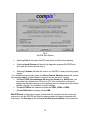
NOTICE
This manual is intended solely to provide instructions for operation of the Compix®
PC2000, PC2000/e, 2000/usb, PC2100, PC2100/e, and 2100/usb Thermal Imaging
Systems and their accompanying Thermal Evaluation Software, WinTES. Compix
reserves the right to change the information contained in this manual without notice.
No warranty, expressed or implied, is made regarding the accuracy of the information in
this manual at any time following its release or for any purpose other than as a guide
to operation of Compix® Systems.
WinTES, the Thermal Evaluation Software for Windows95/98/2000/NT/Me/XP, may be
distributed to others provided the following requirements are met:
1.
No fee, charge, or compensation may be accepted or requested.
2.
The WinTES distribution disk must be copied in unmodified form,
complete with this copyright notice and other files listed in the
“
FI
LES.
TXT”
.
3.
The sole purpose of such distribution is to operate, demonstrate,
analyze, or distribute images produced with equipment manufactured by
Compix.
Other use or distribution of this software without consent of Compix Incorporated is
prohibited.
Copyright 2002 by Compix Incorporated, Tualatin, Oregon.
All rights reserved.
Compix is a registered trademark of Compix Incorporated. TES and WinTES are
trademarks of Compix Incorporated. IBM is a registered trademark of
International Business Machines Corp. Microsoft, MS-DOS, Windows,
Windows95/98/2000/NT/Me/XP are trademarks or registered trademarks of
Microsoft Corporation. All other brand and product names are trademarks or
registered trademarks of their respective companies.
iii
This page was intentionally left blank
iv
Table of Contents
1. INTRODUCTION ..........................................................................................................................................1
2. SYSTEM DESCRIPTION AND OPERATING REQUIREMENTS ........................................................3
3. INSTALLATION AND SET UP ...................................................................................................................6
W INTES SOFTWARE INSTALLATION .............................................................................................................................................. 6
HARDWARE INSTALLATION ............................................................................................................................................................... 6
PC2000 Card ..................................................................................................................................................6
PC2000/e ........................................................................................................................................................8
2000/usb .................................................................................................................................................................8
WinTES version 1.05.0014 or newer is required for proper functionality of the 2000/usb.Mounting the
Camera to its Stand or Tripod ........................................................................................................................8
Mounting the Camera to its Stand or Tripod ............................................................................................... 11
Connecting the Camera ............................................................................................................................... 11
STARTING W INTES........................................................................................................................................... 11
4. WINTES MENUS ........................................................................................................................................ 15
CAMERA CONTROL INTRODUCTION ............................................................................................................................................ 15
5. MAKING THERMAL IMAGES ................................................................................................................ 21
PREPARING TO TAKE IMAGES ......................................................................................................................................................... 21
6. OPERATING SUGGESTIONS ................................................................................................................. 23
FOCUSING ............................................................................................................................................................................................. 23
FRAMING OR DETERMINING WHAT IS BEING VIEWED .......................................................................................................... 24
TEMPERATURE MEASUREMENT .................................................................................................................................................... 25
7. PRINTING AND EXPORTING IMAGES ................................................................................................ 27
8. MAINTENANCE ......................................................................................................................................... 29
CALIBRATION ...................................................................................................................................................................................... 29
GENERAL .............................................................................................................................................................................................. 29
MIRRORS ............................................................................................................................................................................................... 29
9. INSTALLATION AND OPERATING INSTRUCTIONS FOR THE 100 LENS ................................ 31
INTRODUC TION .................................................................................................................................................................................. 31
SET-UP & INSTALLATION ................................................................................................................................................................ 32
OPERATION ...................................................................................................................................................................................................... 3 5
MAINTENANCE ............................................................................................................................................................................................... 3 6
Storage ......................................................................................................................................................... 3 6
Cleaning ...................................................................................................................................................... 36
Preventative Maintenance ........................................................................................................................... 36
Repackaging for Shipment ........................................................................................................................... 37
10. USER SUPPORT ......................................................................................................................................... 39
APPENDIX A. EFFICIENCY, EMISSIVITY, LENS FACTOR, AND NOISE .............................................41
This page was intentionally left blank
vi
1. INTRODUCTION
The Compix® PC2000 family of thermal imagers work with any Windows
95/98/2000/NT/Me/XP based computer. They are designed for non-contact mapping
and measuring of surface temperatures. The heart of the systems is a sophisticated
camera that is sensitive to infrared (IR) radiation. These cameras are reliable, costeffective tools that provide fast, comprehensive evaluations of thermal performance.
Since elevated temperatures are often cited as a cause of failure in electronic
products, thermal phenomena are of particular interest to design and reliability
engineers.
An example of their application is the study of temperature distribution and heat flow on
electronic circuit boards. In an energized electronic circuit, power is dissipated as heat
that produces radiant infrared (IR) energy. The PC2000 captures this radiation and
produces a two-dimensional map, or thermal image, of the object's surface
temperatures.
All configurations of the Compix® PC2000 family of thermal imagers require a
computer for camera control, image storage and display. WinTES software provides
the graphical user interface (GUI) as well as the interface that permits the computer to
communicate with the Compix IR Camera. WinTES requires Windows
95/98/2000/NT/Me/XP and at least a VGA display.
WinTES lets the operator adjust the display, compare images, change colormaps,
compensate for different emissivities, read temperatures at specific locations, compute
area statistics, and show thermal profiles. An important feature of WinTES is the use of
the industry standard TIFF image file format for storing thermal images. This makes it
easy to use the images with other software programs. A second format for image
storage is the Compix format (cpx). This format stores the full 32-bit range of
temperature data. It is larger than the TIFF file format (192k vs 95k) and is readable
only with Compix software such as WinTES or Reporter.
The rest of this manual describes the Compix PC2000, PC2000/e, 2000/usb,
PC2100, PC2100/e, 2100/usb and their operation in more detail.
Note
BEFORE ATTEMPTING TO OPERATE THE SYSTEM YOU SHOULD READ
SECTIONS 2. SYSTEM DESCRIPTION AND OPERATING REQUIREMENTS, 3.
INSTALLATION AND SET-UP, and 5. MAKING THERMAL IMAGES.
1
This page was intentionally left blank
2
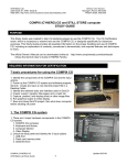
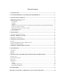
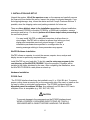
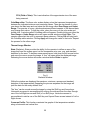
2. SYSTEM DESCRIPTION and OPERATING REQUIREMENTS
The Compix® PC2000 has three principal components: the camera head, the
computer to camera interface, and the Thermal Evaluation Software, WinTES
(see fig. 1). The camera head contains the infrared sensor, mirrors, motors, and
circuitry required to scan, capture and digitize the image data. The interface card
contains the camera control electronics, and digital circuitry required for
communicating with the PC. Calibration parameters are stored in the camera head
allowing cameras to be interchanged between interface types (ISA, USB, LPT)
without compromising calibration. Other than the personal computer, no other
accessories or supplies are required.
Fig. 1
The PC2000 system has been designed to operate in a typical engineering, factory or
sheltered field environment. The system requires a stable surface and well-ventilated
workspace at normal room temperatures. The camera head must be mounted on a
tripod or other stable fixture.Thes
t
andar
df
i
t
t
i
ngsar
ef
ora1/
4“
- 20 threaded male
connector, the type normally found on photographic equipment.
The PC2000/e and 2000/usb require AC power and will work with line voltages from
90 VAC 50 Hz to 240 VAC 60 Hz.
3
The camera head should be located within ten feet (three meters) of the imaging
computer, PC2000/e module, or 2000/usb module. An interface cable of this length is
provided. Cable extensions are not recommended. The /e interface module is
connected to the computer's parallel interface via a standard printer cable. This
second cable is included with the PC2000/e. The 2000/usb interface module is
connected to the Universal Serial Bus (USB) via a standard USB Type A/B M/M
cable.
The camera should be treated with the same care given a good visible light camera or
other optical instrument. Minor vibration can reduce image quality; major vibration or
shock may result in damage. And while the longer wavelength IR energy makes it less
sensitive to dirt, care should be taken to keep the mirrors and detector window clean.
(See Section 8, Maintenance.)
NOTE
There are no components on the PC-circuit-board interface, in the
PC2000/e or 2000/usb interface module, or inside the camera head
designed for user service. Removing the cover of the camera or
interface unit may void the warranty. UNDER NO CIRCUMSTANCES
SHOULD THE SYSTEM BE OPERATED WITHOUT THE COVERS IN
PLACE.
4
WinTES for Windows 95/98/2000/NT/Me/XP Computers
The WinTES software is distributed on a CD-ROM. The software has been designed to
work with personal computers running Windows 95/98/2000/NT/Me/XP. The display
system must be capable of supporting at least the VGA standard.
5
3. INSTALLATION AND SET UP
Unpack the system. Lift off the aperture cover on the camera and carefully remove
the foam strip from behind the mirror. Inspect the system for physical damage. If you
find shipping damage, stop, inform the carrier and call Compix Customer Service. If
possible, store the shipping carton and packing materials for future use.
There are three distinct steps in the installation procedure: software installation;
interface board (PC2000) or module (PC2000/e, or 2000/usb) installation; camera
connection and set-up. You should perform all of these steps before proceeding to
the verification phase.
NOTE
You may install WinTES on additional computers to allow others to
view images. WinTES will run without a camera thus letting you load,
display and manipulate previously stored images. If camera
initialization parameters are specified in a configuration file, a
warning message relating to those parameters may appear.
WinTES Software Installation
WinTES, allows an operator to control the camera, acquire, store, analyze and
display current or previously acquired images.
Install WinTES on your hard disk. To do this, run the setup.exe program in the
root directory of the WinTES CD-ROM. Follow the prompts. Programs will be
installed in the folder stipulated by the user. After completing the installation, store
the WinTES CD-ROM in a safe place as a back up.
Hardware Installation
PC2000 Card
The PC2000 interface board may be installed in any 8- or 16-bit ISA slot. To ensure
proper cooling, leave an empty slot on the component side of the card, or install as the
top card in tower or mini-tower configurations. The PC2000 is shipped with the
dipswitch preset for address 360-hex. Any address from 300-hex to 3FC-hex in
multiples of four is acceptable (e.g. 300, 304, 340, 360).
CAUTION
To prevent damage to the components on the PC2000 interface board,
WEAR A PROPERLY GROUNDED WRIST STRAP OR TOUCH A
GROUNDED METAL OBJECT BEFORE HANDLING THE BOARD.
6
CAUTION
To prevent damage to the computer and interface board, REMOVE THE COMPUTER
COVER ONLY AFTER ASSURING THAT THE COMPUTER IS TURNED OFF.
To install the interface board, remove the rear cover of the expansion slot. Insert the
PC2000 board in an ISA expansion slot pressing it firmly into place. Secure the board
to the chassis with the appropriate size screw.
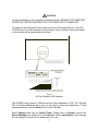
HEX VALUE
200
100
80
40
20
10
8
4
SWITCHES HAVE HEX VALUES AS ABOVE IN THE "OFF"
POSITION. IN THE "ON" POSITION THEIR VALUE IS ZERO.
A9
A8
A7
A6
A5
A4
A3
A2
Fig. 2
I/O Port Selection DIP Switches
The PC2000 comes preset to 360-hex and lists other addresses of 300, 304, 340 and
360. If all these addresses are in use you will need to select new addresses. To find
unused addresses, click the Start button on the Task Bar.
Select Settings then click on Control Panel. Double click on System; choose the
Device Manager and double click on Computer. Select input/output; scroll through
the list looking for a block of four addresses not in use.
7
PC2000/e
CAUTION
To prevent damage to the computer and interface module, BE SURE THE PC POWER
SWITCH IS TURNED OFF AND THAT THE I/F MODULE POWER CORD IS
DISCONNECTED BEFORE CONNECTING THE INTERFACE MODULE TO THE
COMPUTER.
Connect the PC2000/e interface cable to an available parallel printer port on your PC.
Connect the other end of the cable to Centronix® 36-pin connector on the interface
module.
Connect the low-voltage connector of the PC2000/e power converter to the interface
module's mating connector. Plug the converter into an available 110-250 50-60 Hz
VAC power source. You may leave the power module unplugged if you are going to
be using the PC for operations not involving the thermal imager, but it needs to be
plugged in for the following verification.
2000/usb
Connec
tt
he“
A”pl
ug(
t
hewi
deroft
het
wo)oft
heUSBcabl
et
oanav
ai
l
abl
e“
A”
r
ecept
acl
eony
ourPC.Connectt
he“
B”pl
ugoft
heUSB cable to the camera to
computer interface.
Connect the low-voltage connector of the power converter to the interface module's
mating connector. Plug the converter into an available 110-250 50-60 Hz VAC power
source. You may leave the power module unplugged if you are going to be using the
PC for operations not involving the thermal imager, but it needs to be plugged in for the
following verification. NOTE WinTES version 1.05.0014 or newer is required for proper
functionality of the 2000/usb.
8
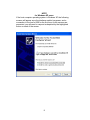
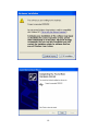
NOTE
for Windows XP users
If the host computer operating system is Windows XP the following
screens will appear once the interface module has power, and a
connect
i
ont
ot
hehost
’
sUSBf
ort
hef
i
r
stt
i
me.Ast
hescr
eensar
e
presented, you will need to respond as depicted by the highlighted
button on each of the screen.
9
10
Mounting the Camera to its Stand or Tripod
Place the PC with the computer to camera interface on a table or other suitable
surface near the camera.
Mount the camera head firmly on its tripod or tabletop stand. Threaded mounting nuts
(1/4 -20) are provided on both the back and bottom of the camera. See Section 10 for
proper tripod setup.
Connecting the Camera
NOTE
POWER TO THE PC AND PC2000/E MODULE SHOULD BE OFF
ANYTIME THE CAMERA IS BEING DISCONNECTED OR
CONNECTED.
The camera is connected to the computer to camera interface through a 3-meter
cable. Connect one end of the cable to the DB44 connector on the back of the
camera, then:
For the PC2000 installation, connect the cable to the DB44 connector on the
PC2000 interface card.
For the PC2000/e installation, connect the cable to the DB44 connector on
the PC2000/e interface module.
For the 2000/usb installation, connect the camera cable to the DB44
connector on the 2000usb interface module.
Turn on the computer's power (or connect the power module to a suitable source of
110-250VAC 50-60 Hz power in the case of the PC2000/e or 2000usb). As the
computer boots up, there may be a brief flutter of the camera mirror if everything is
working properly.
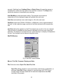
Starting WinTES
Click on the Windows Start button. In Programs find WinTES and click on it. If this is
the first time the system has been operated it will report that the camera is not installed
(see figure below). Selecting Install Camera will launch WinTESCheck.
11
Fig 3
WinTES Start Screen
Selecting Exit will terminate WinTES and return to the Windows desktop.
Selecting Install Camera will launch the diagnostic program WinTESCheck
and open the window shown in fig. 4.
Selecting Continue will allow the user to run WinTES to view previously saved
images.
If no address was previously saved, the Select Camera Address window will contain
the message Select. A valid address is required for the camera to function.
For the PC2000 the addresses will be in hex format, e.g. &H360, etc. You
may select any address from 300-hex to 3FC-hex, however you will need to
change the dipswitch settings on the interface card to correspond to the desired
address. See fig 2 for examples of switch settings.
For the PC2000/e the address will either be PRN1, PRN2 or PRN3.
For the 2000/usb the address will be USB.
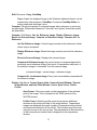
WinTESCheck, a diagnostic program, checks that the computer has the necessary
resources to run the WinTES and that the imaging system is properly connected and
functioning. The first step in the testing is to select a port address for the computer.
12
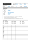
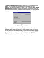
The Select Camera Address window allows the operator to set the system's I/O port
address. The PC2000 will have hex addresses, the PC2000/e will have PRN
addresses, and the 2000/usb will have an address of USB. Click on the Select Camera
Address window's down arrow and select a port address. WinTESCheck will test the
computer for sufficient memory and processor speed and then go on to test the camera
interface, interface communications, detector response, mirror motion and, finally,
initialization.
Fig. 4
WinTESCheck Diagnostics Window
A green or red light will show up next to each function as it is tested. Red will terminate
the test and indicate a possible cause of failure. If the wrong port is selected the
system will fail the camera interface test. This doesn't mean the system isn't working
just that a wrong port address was selected. Try another address until all the lights are
green. If no address works a problem exists. Check for proper seating of the PC2000
board and that all connections are properly made. In the case of the PC2000/e or
2000/usb, check that the module has been turned on. If these steps don't allow the
system to initialize then it is necessary to call Compix Customer Support.
13
This page was intentionally left blank
14
4. WinTES MENUS
When the Compix® PC2000 takes a thermal image or when a TIFF (.TIF) or Compix
(.CPX) image file is opened, the user is relieved from having to deal with many details
associated with handling tens of thousands of temperature measurements. This
section explains how the control and display functions may be used in combinations
that get the most out of the thermal images. Please read this section before
attempting to use the system. Take time to familiarize yourself with the functions and
controls of WinTES and the PC2000, PC2000/e, or 2000/usb system.
WinTES menus are largely self-explanatory and the system permits risk-free
exploration. Once an image has been saved no combination of menu functions will
change the saved temperature data. The exception to this is when another image is
saved under the same file name. Therefore, if you try something and don't get the
desired result, you can always reload the saved image and try again.
Camera Control Introduction
When opened, WinTES will display three windows: Camera Control, WinTES,
Thermal Image- Clicking the cursor on any of these windows will make it the active
window.
Camera Control Window- This window (fig. 5) controls the camera scan. It also
provides for auto scaling of images and/or automatic saving of images.
Fig 5
WinTES Camera Control Window
Two modes of scanning are available with WinTES. These are Continual Scan and
Single Scan. Continual Scan causes the camera to scan, reset and scan until told to
STOP or until Single Scan is selected. Single Scan causes the camera to take one scan
and then stop. The Scan button initiates a scan.
With Continual Scan the operator can control the time from the start of one scan to the
start of the next by using the Period feature. This is accomplished by typing the
desired time (in seconds) in the period window. A normal scan takes approximately 14
seconds thus a period of 20(default setting) would have a scan starting every 20
15
seconds. Switching from Continual Scan to Single Scan will cause the camera to
complete the current scan then wait for the next scan command. The Stop button
causes the camera to immediately stop scanning.
Auto Min/Max provides automatic scaling. The minimum and maximum
temperatures for the displayed image are updated after each scan.
Auto Save automatically saves each image to a file after each scan.
Fast Scan causes the PC2000, PC2000/e, or 2000/usb to scan in approximately 8
seconds. In this mode the image resolution is half that achieved at the normal scan
rate.
Line Scan allows the operator to "park" the scanner over a point or line on a sample.
The pan motion is disabled and the camera is allowed to line scan over a two-pixel
wide area. The display is converted from a x-y thermal map to a display of temperature
Vs time. Fast changes can be detected using this mode.
WinTES Window
Fig. 6 WinTES Control Window
Menus: File, Edit, Compare, Display and Help.
File- Sub-menu items: Open File, Save File, Exit.
Open File- Allows operator to open a previously saved image, configuration, or
colormap. Save File- Allows operator to save an image as a TIFF or as a
Compix Image File that retains the full resolution temperature data. Exitterminates the program.
16
Edit- Sub-menu: Copy, ColorMap.
Copy- Copies the displayed image to the Windows clipboard where it can be
accessed by other programs. ColorMap- Provides a ColorMap Editor for
setting under and overrange colors.
Compare- Permits the operator to compare images with a reference or previously
st
or
edi
mages.Di
f
f
er
encesbet
weenan“
unk
nown"and“
gol
den”boar
dcanqui
ckl
y
be determined.
Compare- Sub Menus: Use for Reference Image, Display Reference Image,
Revert to Scanned Image, Compare to Reference Image, Compare ALL to
Reference.
Use For Reference Image- Current image is saved as the reference to which
others may be compared.
Display Reference Image- Shows the image currently saved as the reference
image.
Revert to Scanned Image- Displays the scanned image.
Compare to Reference Image- the current image is compared against the
previously saved reference image. Each pixel, or temperature data point, of
t
her
ef
er
enc
ei
magei
s“
subt
r
act
ed”f
r
om t
hes
econdi
mage.
(compared image = current image - reference image)
Compare ALL to reference Image- Every scan is immediately compared with
the reference image.
Display- Sub Menus: Cursor, Degree Units, Camera Control Window, Thermal
Image Window, and Heat Flow Window. Cursor- Spot Cursor, Profile
Cursor
Spot Cursor- The cursor reads out the temperature of the selected
point of the image. This is indicated in the TEMP window of the
WinTES window.
Profile Cursor- Selecting profile cursor brings up two additional
windows at the bottom and side of the image window. Temperature
ranges are displayed along with a graph of temperature along vertical
and horizontal extensions of the cursor. The crosshair may be moved
using the mouse or the cursor keys. The temperature at the intersection
of the horizontal and vertical lines is displayed in the temperature
window.
17
Degree Units- Allows for Selecting Celsius or Fahrenheit thermal scale.
Camera Control Window, Thermal Image Window- Activates window
selected.
Heat Flow Window- Selecting this item opens a window with a movable slide
bar. This feature allows the operatort
o“
mov
e”t
hesc
al
eupanddownov
ert
he
displayed image. The minimum and maximum temperatures of the scale define
the range of temperatures displayed. The movable window allows subtle
temperature differences to be accentuated.
Sub-Window- Color Edit contains image display controls.
ColorMap- Thecol
ors
cal
ehassi
x“bui
l
t
-i
n”di
spl
aypal
et
t
es;Def
aul
t
,Rai
nbow,Bl
uet
o
Red, Blue-Green-Red, Grayscale and Medical. Image files may be displayed in any of
t
hesesi
x“
col
or
maps”orpal
et
t
es.Eac
hi
sus
ef
ul
for displaying images and personal
preferences may dictate the operator's choice.
The palettes contain 234 shades of color or grayscale. Changing color palettes
doesn't affect temperatures in the image.
The Max Color value is the highest temperature displayed in the color palette. The
Min Color value is the lowest value displayed in the color palette.
The values above and below the MIN and MAX are useful for setting and displaying
“
ov
er
-range and under-r
angev
al
ues”
.Tosetupperorl
owercont
r
ol
or“
ov
er-r
ange”
values, double click on the color bar. A secondary window will appear and the operator
cansel
ec
tacol
ort
osi
gni
f
y“
ov
erandunderr
ange”v
al
ues.Sel
ectt
hecol
orandt
el
lt
he
program to apply the chosen colors. The top and bottom portions of the colorbar will
now display those colors. Subsequent display of images having values outside the
colorbar will show the overrange colors.
Min-Max- Auto range reads the minimum and maximum temperatures in the image
and sets the min and Max so they encompass the display range. The system
automatically redraws the image with the new scale.
Fit ColorMap- Auto scale fits the scale so that one cycle of the colormap is used to
display the image data.
Redraw- Refreshes the image. This is done automatically when Color Scale is
changed. It is not automatically updated when thermal correction factors are
changed.
18
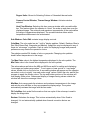
Thermal Correction- This is an auxiliary window, which is opened when Correction is
clicked. A series of controls are made accessible.
Ambient, Emissivity, Lens factor, Field of view (FOV), Focus (in).
Ambient- the Emissivity is calculated about this value. Set the value to the
temperature of the ambient in which the instrument is operating.
Fig. 7
WinTES Control Window with Thermal Correction Open
Emissivity- All materials have characteristic emissivities, which are, less than
1.0. This means that non-black bodies radiate IR at a lower rate than does the
ideal source. Practically speaking this means that an object with a lower
emissivity will appear to be closer to ambient than a black body having the same
temperature. The Emissivity setting corrects for this effect and provides the user
with the correct temperature reading for that object. Values can be selected from
1.00 to 0.01.
Lens factor- This correction compensates for the attenuation introduced when
the system is operated with the 7.5x lens. Without the correction, temperatures
read by the system would appear lower than their true temperatures. Each lens
comes with its lens factor specified on its serial number label. Nominally this is
around 65%.
Focus (in)- Temperature readings can be affected by the distance of the
camera from the object being measured. This setting represents the distance in
inches from the front of the camera to the object and corrects for any distancerelated errors.
19
FOV (Field of View)- This is an indication of the approximate size of the area
being scanned.
ColorMap editor- The three color scales display colors that represent temperatures
between the indicated minimum and maximum values. There are two bands of colors,
one above the Max temp and one below the Min temp called Over Range and Under
Range. The operator in a way, which emphasizes different aspects of the thermal data,
may change their colors. To edit the colors, place the cursor on the color scale and
double click. A window called ColorMap editor will appear. Double clicking on either the
Over Range or Under Range colors will open another window entitled Color. The
operator can select the color to represent these extremes. Clicking OK will bring back
the ColorMap editor window. Clicking Apply will change the value to that color. Repeat
the process for the other range.
Thermal Image Window
Stats (Statistics)- Stats provides the ability for the operator to define an area of the
image and have the system report out the temperature min, max, avg. and standard
deviation for the area. To define a measurement area, hold down the left mouse button
andmov
et
hec
ur
soracr
osst
hei
mage.A“
box
”wi
l
lopenwi
t
hi
nt
hedi
spl
ay
edi
mage.
Releasing the mouse button will cause a window labeled Stats to appear.
Fig. 8
Statistics Window
Within the window are displayed the maximum, minimum, average and standard
deviation of the temperatures. Repeating the process anywhere on the image will
yield the data for the newl
ydef
i
ned“
box
”
.
The“
box
”canbemov
edacr
osst
hei
magebyusi
ngt
heShi
f
tkeyandAr
r
owkey
s.
Horizontal movement is accomplished by moving one side and then the other through
use of the Left/Right arrows and Shift (or no-Shift) keys. Vertical movement is
accomplished in similar use of the Shift key and Up and Down arrows instead of Left or
Right arrows.
Cursor as Profile: This function constructs line graphs of the temperature variation
along a horizontal and vertical line.
20
5. MAKING THERMAL IMAGES
Once you have completed the set-up steps of section 3, the system is ready for
operation.
Definitions: The top of the camera is the end with the focusing knob. The side with
the large opening (aperture) is the face or front. The opposite side, with the cable
connector, is the back.
Preparing to take images
With its face toward the subject, position the camera head so it is approximately
centered over the area to be scanned. The top edge will correspond with the top of
the display. The face of the camera head should be parallel to the surface of the
subject.
The area scanned by the camera depends on the distance from the camera to the
subj
ect
.Aswi
t
ha“
box
”camer
a,t
hegr
eat
ert
hedi
st
ancet
hel
ar
gert
hef
i
el
dofv
i
ew.
WinTES displays the field of view when the distance from the camera to the object
(focus) is entered in the correction menu. Set the camera head at a distance
appropriate for the size of the subject. It should be no closer than 2.0 inches. The
focusing knob has a scale showing focal length in inches and mm. For an initial focus,
turn the knob to where the distance indicated by the index mark matches the distance
from the camera to the surface of the subject.
Start WinTES by double clicking on the WinTES icon. If the camera has been set-up
previously the system will configure itself automatically. To begin scanning select
Single Scan or Continual Scan and click on the Start “
but
t
on”
.Thedef
aul
tv
al
uef
or
Delay is 20 seconds. This is the time from the start of one scan to the start of the next
scan. The user can select values to best suit their application.
While the system is scanning you may improve the focus by making small adjustments
of the focusing knob until edges appear sharp. Remember that heat will flow from one
obj
ectt
oanot
hert
hust
her
mali
magesmayappear“
smear
ed”whencompar
edt
o
photographic images. (See Section 6 for suggestions on focusing and framing.)
Single scan will take one image, then stop. Continual scan will periodically scan,
depending upon delay, until commanded to Stop. You can stop either process at
any time by selecting STOP. Selecting single scan while in the middle of a multi
scan will cause the scanning to stop at the end of the current scan.
21
This page intentionally left blank
22
6. OPERATING SUGGESTIONS
Focusing
The optical system of the Compix® PC2000 camera operates in the same way as a
photographic camera. One implication of this is that the system's large aperture
r
esul
t
si
nashor
tdept
hoff
i
el
d.Neart
hemi
ddl
eofi
t
sf
ocalr
ange(
12”
-15”
)
, a depth of
f
i
el
dar
ound1/
2”woul
dbet
y
pi
cal
.Att
woi
nches,t
hedept
hoff
i
el
dmaybel
esst
han
1/
4”
.I
nanycase,f
ocusi
ngi
si
mpor
t
antt
oi
magequal
i
t
yaswel
last
emper
at
ur
e
accuracy.
Generally, items seen in a thermal image are not as crisp as when viewed in a video
image. As a result, when first viewing an image it may be hard to determine whether
the camera is well focused or not. This will become easier with practice.
The PC2000 camera utilizes a manual focusing mechanism. The first step in focusing
is to measure or estimate the distance from the forward edge of the aperture bezel to
the subject. If the subject isn't flat, use the average distance, or use the distance to the
area of greatest interest. With the focus index set to match the camera to object
distance take a Single Scan. After the scan is completed, click Min-Max. This will set
the Min and Max temperatures so that the range displayed encompasses the
temperatures in the scanned area. You should now see an image from which you can
begin to fine tune the Focus. In the Camera Control window set the scan for Continual
and start scanning. While the system is scanning make a series of small focusing
adjustments and observe the changes. Look for improvements in the definition of the
outlines of components such as crystal cans, IC legs or board mounting hardware and
mounting holes. Straight edges of larger components are also good guides. Entering
this focus distance in the Correction window will indicate the camera's field-of-view
(FOV) as well as provide a correction factor to compensate for variations introduced
when the camera is moved away from the 10 inch focal length used in calibrating the
instrument.
Many users find this process easier with the Grayscale colormap, since black and
white images tend to appear more natural. A technique, which gives excellent results,
involves indirectly shining a 40 to 60 W incandescent light on the unpowered target.
To the PC2000 this is the functional equivalent of an infrared flashbulb. The lamp
illuminates the target and the camera displays the reflected IR energy. The resulting
image will look much like a visible light picture. Edges will be sharply defined,
components will stand out in sharp relief and fine focusing will be easier.
To use this technique, place the lamp about two feet above, and at an angle of about
45° to an unpowered target. Don't shine the light directly into the aperture of the
camera. Use Grayscale colormap and take an image. You may have to experiment
with the position of the lamp to get the best result. When finished focusing, turn off
the lamp as high levels of reflected infrared will distort the temperature readings.
Framing or Determining What is Being Viewed
23
Framing involves two things: first, the aiming of the camera so the target is centered in
the image; second, being able to relate specific points in the thermal image to the
corresponding locations on the target. The same factors that make it more difficult to
focus a thermal image can also make it harder to frame properly. Many users find their
first thermal images are ambiguous and confusing. But image interpretation is quickly
learned if the user has a working knowledge of the object being scanned.
Remember, it is important to have a well-focused image.
Operating hint: Look for obvious reference points. Typical hot spots are power
resistors, power transistors, and power IC's. Cold or low emissivity components would
normally include mounting brackets, metal capacitors or crystal cans and bare copper
runs. Surface mount devices, hybrids, etc. are often framed by the contrasting colors
of surrounding heat sinks or substrates. Packaged IC's may be identified by the rows
of legs or leads on the sides.
Edges of circuit boards are usually easy to find. In an energized board, conduction
through the substrate and ground plane normally creates some visible differential
heating to the edge of the board. Providing a good background can make the edges
easier to see. A dark, matte finish material such as cardboard or black paper behind
the board can improve contrast.
Simple markers can be used as pointers. Any small non-conductive (for safety
reasons) object at room temperature will work. Plastic tools, non-metallic rulers are
also useful. Put the marker on the target as a pointer or an edge indicator, and then
take an image. The marker should show up as a distinct dark area against the warmer
background of the board and its components. Objects you take out of your pocket will
already be warm and may not show up in the image. Some users have reported good
success with active (hot) markers. The wire will appear as a distinct hot pattern in the
thermal image. The focusing technique described above of using an incandescent
lamp or other infrared source is also useful for framing. Make a reflected IR image
using that technique. Then, with the lamp off, make a normal thermal image. Watch
the display as the thermal image overlays the reflected IR image and you will see
which points correspond.
24
Temperature Measurement
The Compix PC2000 is a sensitive instrument that has the capability to detect small
temperature differences within the range typically encountered by engineers. However,
non-contact temperature measurements are affected by a number of variables that can
change the accuracy of temperature measurements. The following techniques will help
improve the accuracy of measurements made with the PC2000 system.
Be Consistent
Often all that's needed are good relative measurements. The engineer wants to
know how one temperature compares with another. Consistency is the key.
- Maintain the same environmental conditions, e.g., ambient temperatures,
ventilation and the presence of other heat sources in the room.
- Maintain the same physical set-up for the system. Put the boards in the same
orientation -- flat or upright, the same distance from the camera and the same
relative position on the display.
-Maintain the same electrical set-up: same power inputs, same program to
exercise it. While a circuit board may take several minutes to reach thermal
stability, it is not necessary to wait for the board to stabilize, but comparative
readings between boards will be more accurate if both circuits are at
approximately the same point in their warm-up cycles.
- Use the same scan rate in both cases.
Minimize external sources of infrared energy.
The Compix PC2000 measures temperature using emitted infrared energy, i.e. the
infrared energy generated by the target. Objects also reflect infrared energy from
their surroundings.
The PC2000 system (or any other infrared system) can't tell the difference between
reflected and emitted energy. Therefore, reflected energy is a potential source of error.
Some reflected infrared (IR) energy is unavoidable and the PC2000 will automatically
compensate for typical levels of external IR energy, which are uniformly distributed over
the target. Nevertheless, it will be helpful to minimize significant sources of external IR,
particularly those that may not be uniformly distributed.
Other sources to avoid are direct sunlight coming through a window and shining on
the target, or heat from nearby electronic devices. A general rule of thumb is that if
you can feel heat from a source near the target, then it will affect the accuracy of the
image.
25
Minimize the reflectivity of the target.
Another aspect of the problem described above is that some objects naturally reflect
more infrared energy than others do. Unfortunately, due to the laws of physics, good
reflectors are poor emitters of infrared (emissivity<<1.00). As a result, these objects
produce a high ratio of reflected (undesirable) to radiate (desirable) infrared, thus
yielding less accurate temperature readings.
The solution is to reduce the reflectivity of these objects. Fortunately, surfaces that are
reflective to infrared are usually reflective to visible light. So look for bright, shiny or
metallic surfaces, as they will be the problem.
There are several easy ways to reduce reflectivity while minimally effecting the
component's thermal performance. A strip of electrical or masking tape on the top
surface is one. Anything with a matte surface is a good choice. Or a quick, light
buffing with fine emery paper -- just enough to break the surface sheen -- will also
help. Most conformal coatings and solder masks provide a low reflectivity surface for
thermal images.
Adjust the Emissivity setting
The default Emissivity setting of the PC2000 system is 1.00. This is appropriate for
the highly emissive (low reflectivity) materials that are most common on circuit
boards. For components with lower emissivity, temperature accuracy will be improved
if the PC2000 system's Emissivity setting is adjusted to match the component's
emissivity. Emissivity tables are available for many of the materials commonly used
on printed circuit boards.
26
7. PRINTING AND EXPORTING IMAGES
WinTES produces TIFF (Tag Image File Format) images that adhere strictly to the
TIFF standard Revision 5.0 for Class-P (Palette Color) Images. Some software
applications, which claim to be TIFF compatible use a limited subset of the TIFF
specification and may not import Compix TIFF files, so universal compatibility is not
assured.
The most reliable way to export a color image is to use the Copy command from the
menu. This puts the image into the clipboard from where it can be pasted into the
appropriate document. Alternatively, Print Screen may be used to copy a full
Windows screen to the Clipboard or Alt Print Screen will copy only the active window
to the clipboard. These objects may be pasted into a Word, WordPerfect or other
word-processing document.
Additionally, the TIFF thermal image files may be opened in any of a number of
applications programs. Finally, images may be captured and saved using any of a
number of commercially available screen capture programs.
From these word processing or screen capture programs it is a simple matter to print
to a file or printer.
27
This page intentionally left blank
28
8. MAINTENANCE
Calibration
It is recommended that instrument performance be verified once a year. The
instrument should be compared against a calibrated blackbody source. It is
recommended the instrument be returned to the factory for repair and recalibration.
General
The exterior of the camera, PC2000/e module, and 2000/usb module can be dusted
with clean, low-pressure air or a clean, soft cloth. For more persistent dirt, scrub
gently with a damp cloth.
Mirrors
Inspect the camera's mirrors periodically. If used in a relatively dust-free environment
and if the aperture is covered while the system is not in use the mirrors shouldn't
require frequent cleaning. When the mirrors are visibly dusty, clean them as follows:
Remove the plastic bezel surrounding the camera's aperture. With the camera firmly
supported and facing you, carefully reach inside with your thumbs and press outward
on the sides of the bezel while pulling forward. When the bezel is off, set it aside.
Turning the focusing knob to the high end of its scale will move the focusing mirror to
where it is accessible for cleaning.
The cleaning techniques for the mirrors are the same as for a high quality camera
lens. Usually dust can be removed with a blast of clean, low-pressure air or a soft,
gentle brush. For more thorough cleaning, use a non-abrasive, lint-free cloth with a
photographic wetting agent or alcohol.
Replace the bezel by reversing the steps to remove it.
29
This page intentionally left blank
30
9. Installation and Operating Instructions For the 100 Lens
Introduction
The 100 is a collection of accessories for the PC2000, PC2000/e, or 2000/usb which
together form the PC2100, PC2100/e, or 2000/usb respectively, and which consists of
the following:
Alternate bezel, which holds the magnification lens. The magnification lens
itself consists of three precision optical elements made of silicon and
coated for optimum performance in the 3 to 5 micron wavelength band.
These elements are housed in a black anodized aluminum holder
mounted in the front panel of the alternate bezel. Two lens dust covers
are included, one for each side of the lens. The two lens dust covers
are identical.
A sturdy bench top stand to support the camera with lens attached securely
over the object to be imaged and which provides a means for making
minute adjustments in the height (or Z-axis) position of the camera.
A large hex wrench for tightening/loosening the clamp arm that holds the
camera/lens combination.
Optional Accessories:
A micrometer-style X-Y positioner mounted to the base of the bench
top stand on which the object to be imaged is mounted.
31
Set-up & Installation
Assembling the Heavy-duty Stand
1. Attach the post to the base plate using the long-shaft socket driver.
2. Install the safety clamp
3. Install the camera support arm and pinion assembly onto the vertical shaft. Make
sure the arm support is oriented to the top of the pinion assembly. Gradually lower
the assembly until the pinion engages the rack. Do not force.
Installing the camera on the bench top stand
1. Position the safety ring four inches (100mm) or more above the base. Tighten it
securely in this position. Later you will adjust the height of this ring so that the lens
cannot possibly touch or crash into the object being imaged.
2. Remove the standard bezel from the camera: Lay the camera on its back with
camera cable disconnected. Carefully reach inside both sides of the bezel and push
out as you pull the bezel away from the camera. Avoid touching the mirror. It may be
easier to cross you arms and slip your thumbs inside so that you can push outward
controllably with enough force to remove the bezel easily.
3. Remove the internal lens cover from the magnification lens. It is not necessary to
twist the lens cover to remove or install it, but if you do, always turn it clockwise so
as not to have a tendency to loosen the lens-retaining ring. Inspect the lens surface
and clean it if necessary (see section 4-2). Note the value to be used for the Lens
Factor as indicated on the label inside the lens-bezel assembly. Note which end
should be up. Slide the lens-bezel assembly into position. Use your fingers to pull
the sides apart as the assembly is pushed all the way into place. Make sure the
protruding setscrews engage the holes in the camera sides.
4. Make sure the clamp bolt of the camera support arm is fully loosened. Remove the
external lens cover. After assuring that the lens-bezel assembly is properly installed,
turn the camera over and carefully insert the lens housing into the large hole in the
camera support arm. The focus knob of the camera may be oriented away from the
post or to either side. Tighten the arm clamp using the hex wrench just enough to
hold the camera securely and prevent it from twisting. Do not over tighten!
5. Replace the external lens cover until you are ready to actually start imaging. The
external lens cover may be twisted, if desired, in either direction. Store the internal
lens cover in a safe place where you can find it later if you want to remove the lens
32
and use the camera for imaging larger objects. The lens covers are
interchangeable.
6. Re-position the safety ring so that the camera cannot come down too close to the
object being imaged. Tighten the safety ring. Always keep the safety ring positioned
and tightened to insure that the lens cannot fall onto, or come in contact with the
object being imaged.
33
Mounting the positioner (if applicable)
The optional positioner, if ordered, is shipped separately to prevent damage to the
micrometer adjustment mechanisms. It is to be installed on the base of the bench
top stand using the four threaded holes.
1. Remove the four #6-32 socket-head cap screws from their holes in the base plate.
2. Position the X-Y positioner over these four holes. The positioner may be mounted in
any of four orientations. The most common is to have one adjustment in front and the
other to the right. However, on a crowded bench, better protection against damage
and accidental change may be worth the inconvenience of mounting one adjustment
to the back and the other to either side as dictated by the environment or by the
preference of the operator.
3. Install all four cap screws finger tight. It may be necessary to move the stage of the
positioner to get satisfactory access. Avoid manually moving the stage against the
force of the return springs, and, especially, DO NOT LET THE STAGE RETURN
OUT OF CONTROL TO ITS REST POSITION. (Repeatedly letting the stage slam
against its stops under force of the return springs could damage the micrometer
mechanisms.)
4. Finally, tighten all four screws uniformly. Do not over tighten. Tighten them just
enough to keep them from vibrating loose or allowing the positioner to wiggle when
operating the micrometers. Use a torque screwdriver, if possible, and tighten the
screws to 40 in-oz.
Removal/Disassembly
To remove the lens assembly in order to use the camera for imaging larger objects,
or for shipment, simply reverse the above steps.
34
Operation
Set up the object to be imaged on a stable surface. (If the grid of #6-32 threaded holes
of the optional X-Y positioner are used, be careful that the screws never engage
beyond 0.2 inches (0.5mm) and protrude through the stage. Nylon screws are
recommended. Alternatively, a sample can often be installed satisfactorily using
masking tape or equivalent.)
Adjust the safety ring so that, with the lens cover in place, the camera cannot come
down any further than to have the lens cover almost touching the sample.
To raise or lower the camera, adjust the tension as needed, tight and slowly rotate the
height adjustment knob. The tension will automatically increase as you lower the
camera, or decrease as you raise it. To maintain constant tension, turn both knobs
together.
Connect the camera cable, apply power, and proceed to operate in the normal
manner (see PC2000 manual).
Raise the camera several inches above the object being imaged and remove the lens
cover.
CAUTION: Never touch the lens or allow any object to touch or strike the lens.
Set the focus distance knob on the camera to 15 inches (375mm). Carefully
lower the camera to within 0.3 inches (7.5mm) of the object to be imaged. This
distance is measured from the forward most (lowest) surface of the lens housing to the
plane of the object.
Set the Lens Factor according to value printed on the label on the inside of the lensbezel assembly. To set the lens factor in WinTES, click on the Image Data button. This
will expand the WinTES window and add a Thermal Correction section in which Lens
Factor and Emissivity can be set. Focus distance should be set to 15 inches (375mm).
The FOV (Field of View) is not valid when using the magnification lens. In the case of
the DOS-base TES software, the Lens Factor is entered using the corresponding item
in the TES Display menu. The use of the Lens Factor is necessary to compensate for
the attenuation introduced by the lens. See Appendix A for further discussion of the
Lens Factor.
If the device is powered (or illuminated from a small nearby incandescent source) an
image should be obtained. To adjust the focus, adjust the height of the camera. When
reasonably good focus is achieved, further refinement may be made adjusting either
the height or the focus knob. Overall performance will be best if the camera focus
setting is kept between 12 and 18 inches (between 300 and 450mm).
35
Maintenance
Storage
Use the lens cover to protect the exposed lens whenever the 100 is not in use. If for
any reason the magnification lens is removed from the camera, be sure to protect both
internal and external lenses with the lens covers.
Cleaning
Small amounts of dust or lint on the lens surface will have little or no effect on the
performance or calibration of the lens. It is possible to degrade the lens surface by
improper or excessive cleaning techniques. Use the following cleaning techniques
carefully and not too frequently.
To remove loose dust or debris, use a gentle stream of dry air. Aerosol-type cans of
clean dry air available at camera and electronic stores are suitable for this purpose. For
more persistent loose dust or debris you may use a camelhair brush or soft cotton
swab ("Q-tip"). Do not use lens tissues: Lens tissues intended for eye glasses
contain chemical additives and lens tissues available in camera stores are often
not soft enough.
Avoid touching the lens surface with your fingers. If you do need to clean off
fingerprints or other more resistant material, use clean alcohol or acetone to dampen a
soft cotton swab, gently dab, and swipe the spot or fingerprint. If you look at the lens
surface under magnification you will probably notice a few tiny defects in the coating
that have no measurable effect on the performance of the lens; But if you mistake such
a defect for debris and try to remove it you can make the defect larger.
Preventative Maintenance
Whenever you remove or install the lens assembly onto the camera check to make
sure the inner lens retainer hasn't turned and that the beveled portion of the retaining
ring is exactly aligned along the bottom. Newer lenses have no beveled portion in
which case this check may be ignored.
Occasionally inspect all parts of the lens assembly, bench top stand, and X-Y
positioner for damage and for accumulation of dust and debris. Clean and lubricate
(using a light oil) all moving parts as needed.
36
Repackaging for Shipment
DO NOT SHIP THE CAMERA WITH THE LENS INSTALLED. Use the lens covers
and provide plenty of packing material. Refer to the PC2000 manual for camera
packing instructions.
To ship the bench top stand it is recommended that the X-Y positioner be removed
and packed separately. Make sure the support arm and safety clamp are tight, and
use plenty of packing material.
37
This page was intentionally left blank
38
10. USER SUPPORT
User support is available by phone, mail, e-mail or in person at Compix' offices in
Lake Oswego, Oregon. Support will normally be available from 8:00 A.M. to 5:30
P.M. Pacific Coast Time, Monday through Friday, excluding national holidays.
User support is generally free of charge on issues relating to interpretation of this
manual, the proper operation of the system, routine maintenance and warranty
service. Consultation is generally not available on image interpretation problems, fault
diagnosis, system modifications or application specific issues, particularly those
outside the field of electronic test.
Compix reserves the right to determine, at its sole discretion, the extent of user
support made available to any user. A user may be asked to furnish proof of
ownership of a Compix PC2000 system before receiving support.
For phone support call (503) 639-8496, identify yourself as a user of the Compix
PC2000 system and ask for User Support. It may be helpful for you
to have the serial number of your PC2000 system and the version number of WinTES
available when you call.
Visit www.compix.com for technical articles, price lists, product photos, and other
information on current products.
For support by mail write to:
Compix Incorporated
Attn.: User Support/PC2000
P.O. Box 885
Tualatin, OR 97062-0885
If you want to visit us in person, please call us at the number above for directions and to
make sure the person best equipped to help you will be available when you arrive.
Our office location/ shipping address is:
Compix Incorporated
15824 SW Upper Boones Ferry Rd
Lake Oswego, OR 97035-4066
39
This page was intentionally left blank
40
APPENDIX A.
Efficiency, Emissivity, Lens Factor, and Noise
Both emissivity and lens factor work alike to express the efficiency with which radiation
from that object reaches the sensor of the camera. Use what you already know about
emissivity effects to understand the effect of the Lens Factor.
The overall value for efficiency may be determined by multiplying the
emissivity and lens factor. In the following examples, the first three lines
represent mathematically equivalent situations:
Emissivity
.49
1.00
.70
1.00
Lens Factor Efficiency
1.00
.49
.49
.49
.70
.49
1.00
1.00
Background noise is exaggerated by non-unity lens factor or emissivity
settings. To fully understand this it may be helpful to view the top two lines of
the Apparent Temperature table are reproduced below. The first entry of
the second row simply indicates that for a 100% emissivity object, 30oC
would be reported; the second entry indicates that a real surface of 0.9 (90%)
emissivity would appear the same as a blackbody of only 29.1 o C.
Another way of looking at the information contained in this table is to realize
that if the emissivity were set to 90%, then a black body of only 29.1 o C would
be converted to read out as 30o C. Similarly, the third entry from the end in the
first row indicates that a blackbody of only 22.9o C would be converted to read
30o C if the emissivity setting were 20%.
Apparent Temperature as a function of
Actual Surface Temperature º C (down) and Emissivity % (Across)
100
30
90
29.1
80
28.3
70
27.4
60
26.5
50
25.6
40
24.7
30
23.8
20
22.9
10
21.9
0
21.0
The background noise reported with a 100% efficiency setting (100
emissivity and 100 lens factor) will typically span two to three degrees.
Suppose a particular instrument reports background noise of 21o C to 22.9o C.
Suppose these values were converted with a lens factor of 20%. By
definition, 21 o C is converted to the same value, 21 o C. But 22.9o C, as
shown in the table fragment above, would be reported as 30.0o C, resulting
in a 9-degree span for the temperature-equivalent background noise.
41


![VTW Software Operation manual[PDF:17.4MB] - FOR](http://vs1.manualzilla.com/store/data/005725901_1-df2c6d7f9199f46fcf33ffa12e63545b-150x150.png)