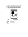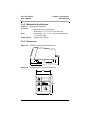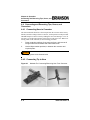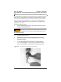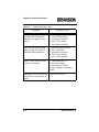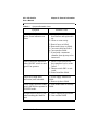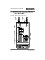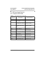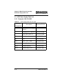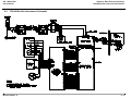
1
250 - 450 Sonifier
Analog Cell Disruptor
User’s Manual
EDP 100-413-016
Rev. B
BRANSON Ultrasonics Corporation
41 Eagle Road
Danbury, Connecticut 06813-1961 U.S.A.
(203) 796-0400
http://www.sonifier.com
100-413-016 Rev. B
250 - 450 Sonifier
User’s Manual
Manual Change Information
At Branson, we strive to maintain our position as the leader in ultrasonic plastics
joining, cleaning and related technologies by continually improving circuits and
components in our equipment. These improvements are incorporated as soon as
they are developed and thoroughly tested.
Information concerning any improvements will be added to the appropriate manual section(s) at the next printing. Therefore, when requesting service assistance
for specific units, refer to the printing date which appears in the lower right corner
of this page.
Patents and Copyright
Copyright © 1998 by Branson Ultrasonics Corporation, Danbury, Connecticut, U.S.A.
All rights reserved.
Branson Ultrasonics Corporation equipment is manufactured under one or
more of the following U. S. Patents:
4,973,876; 5,435,863, 5,855,706
NOTICE
Sonifier® is a registered trademark of Branson Ultrasonics Corporation,
Danbury, Connecticut, U.S.A. Other trademarks and service marks
respectfully mentioned herein are held by their respective owners.
NOTICE
Loctite is a registered trademark of Loctite Corporation, Newington, CT.
Other trademarks and service marks mentioned herein are held by their
respective owners.
100-413-016 Rev. B
Regulatory Compliance
Sonifiers sold in Europe after 1/1/01 are CE compliant. They have new part numbers. They conform to EN55011, EN 61010-1, EN61000-3-2, EN61000-3-3,
EN61000-4-3, EN 61000-4-6 and ENV50204. They take advantage of Branson
latest System Protection and Autotune technology.
System protection constantly monitors various operating parameters of the power
supply. It if senses conditions that could cause the power supply to overload it will
shut the power module down. To reset the power supply after an overload condition has been sensed turn the power switch off and then turn it back n. On Digital
Sonifiers the test function will reset the power module.
Autotune optimizes the operating frequency of the power supply so that it is consistent with the acoustic tooling. To facilitate the auto tune process the power supply performs a seek function upon first powering up the unit. When first powering
up, the unit will perform a brief cycle at low amplitude so that the power supply
can determine information about the acoustic tooling including it’s operating frequency.
The output meter on new CE Analog Sonifiers now reports Watts. It is no longer
necessary to use the tables in the manual to determine output watts based on meter
reading vs. output control setting.
On CE Digital Sonifiers amplitude is now set digitally from the front panel similar
to all other operating parameters.
100-413-016 Rev. B
250 - 450 Sonifier
User’s Manual
Warranty
When used in accordance with written instructions and under normal operating
conditions, Branson Ultrasonics Corp. equipment is guaranteed to be free of
defects in MATERIAL and WORKMANSHIP for two (2) years from the date of
original delivery by BRANSON or by an authorized representative. Any unit
which proves defective during the stated period will be repaired free of charge or
replaced at the sole discretion of Branson Ultrasonics Corp., F.O.B. Danbury,
Connecticut, or an authorized repair station as advised by BRANSON, provided
the defective unit is returned properly packed with all transportation charges prepaid. A limited warranty as specified may apply to certain components of the
equipment.
Warranty Exceptions
This warranty shall not apply to equipment subjected to misuse, improper installation, alteration, neglect, accident or improper repair.
This warranty is limited to the original purchaser and is not transferable.
Horns and tips fabricated by Branson for use in equipment described in this manual are manufactured to exacting parameters. Using altered or modified horns and
tips or horn and tips otherwise unqualified by Branson can product undue stresses
that may damage the equipment. Equipment failures resulting from using unqualified horns and tips are not covered by the Branson warranty.
Microtips are designed to give maximum mechanical energy output. Since they
operate close to the stress limits of titanium, Branson cannot guarantee Microtips
against failure.
CONTACT YOUR BRANSON REPRESENTATIVE OR BRANSON ULTRASONICS CORPORATION, DANBURY, CONNECTICUT, SHOULD YOU
HAVE ANY QUESTIONS CONCERNING HORN QUALIFICATION.
1-800-732-9262
100-413-016 Rev. B
100-413-016 Rev. B
250 - 450 Sonifier
User’s Manual
Table of Contents
1
Safety and Support - - - - - - - - - - - - - - - - 1-1
1.1 For Safety of Operating Personnel
1.2 About this Manual - - - - - - - 1.3 Purpose of the Equipment - - - 1.4 Main Components - - - - - - - 1.5 Principle of Operation - - - - - -
2
-
-
-
-
-
-
-
-
-
-
-
-
-
1-1
1-1
1-2
1-2
1-3
Introduction - - - - - - - - - - - - - - - - - - - - 2-1
2.1 250/450 Sonifier Power Supply Front Panel - - - - - - - - - 2-1
2.2 Model 250/450 Sonifier Power Supply Rear Panel - - - - - - 2-3
2.3 Specifications - - - - - - - - - - - - - - - - - - - - - - - 2-4
2.3.1 Electrical Specifications - - - - - - - - - - - - - - - 2-4
2.3.2 Mechanical Specifications - - - - - - - - - - - - - - 2-5
2.3.3 Dimensions - - - - - - - - - - - - - - - - - - - - - 2-5
3
Delivery and Handle - - - - - - - - - - - - - - - 3-1
3.1 Unpacking and Handling 3.2 Placement of Equipment 3.3 Power Requirements - - 3.4 Setup Procedure - - - - -
4
-
-
-
-
-
-
-
-
-
-
-
-
-
-
-
-
-
3-1
3-1
3-2
3-3
Operation - - - - - - - - - - - - - - - - - - - - - - 4-1
4.1 General Operation - - - - - - - - - - - - - - - - - - - - - 4-1
4.1.1 Timed Operation - - - - - - - - - - - - - - - - - - 4-1
4.1.2 Continuous Operation - - - - - - - - - - - - - - - - 4-2
4.1.3 Pulsed Operation - - - - - - - - - - - - - - - - - - 4-2
4.2 Operating Considerations - - - - - - - - - - - - - - - - - 4-3
4.2.1 Limiting Temperature Rise - - - - - - - - - - - - - 4-3
100-413-016 Rev. B
i
4.2.2 Vessel Capacity and Speed of Temperature Rise - - 4-4
4.2.3 Minimizing Undesirable Factors - - - - - - - - - - - 4-5
4.2.4 Sterilizing and Preventing Cross-Contamination - - - 4-6
4.2.5 Disrupting Tissues and Solids - - - - - - - - - - - - 4-6
4.2.6 Using Glass Powders with Solution - - - - - - - - - 4-7
4.3 Testing the Equipment - - - - - - - - - - - - - - - - - - - 4-7
4.4 Connecting and Removing Tips, Horns, and Converters - - - 4-8
4.4.1 Connecting Horn to Converter - - - - - - - - - - - 4-8
4.4.2 Connecting Tip to Horn - - - - - - - - - - - - - - - 4-8
4.5 Horn and Micro Tip Amplitudes- - - - - - - - - - - - - - 4-10
5
General Information - - - - - - - - - - - - - - - 5-1
5.1 General Information - - - - - - - - - - - - - - - - - - - - 5-1
5.1.1 System Trouble Analysis Chart - - - - - - - - - - - 5-1
6
Main Electrical Assembly - - - - - - - - - - - - 6-1
250/450 Sonifier Assembly 6-2
6.2 250 Power Supply Parts List - - - - - - - - - - - - - - - - 6-3
6.2.1 Domestic 100-132-1622 - - - - - - - - - - - - - - 6-3
6.3 450 Power Supply Parts List - - - - - - - - - - - - - - - - 6-4
6.3.1 Domestic 100-132-1623 - - - - - - - - - - - - - - 6-4
6.4 250/450 Sonifier Interconnect Schematic - - - - - - - - - - 6-5
A
The Effects of Ultrasonic Irradiation on Various
Biological Materials - - - - - - - - - - - - - - - - A-1
B
How to obtain Further Assistance - - - - - - - B-1
Customer Service, Technical Support, and Applications Assistance
- - - - - - - - - - - - - - - - - - - - - - - - - - - - - B-1
Equipment Failure Support - - - - - - - - - - - - - - - - - - B-1
Returning Equipment - - - - - - - - - - - - - - - - - - - - - B-1
ii
100-413-016 Rev. B
250 - 450 Sonifier
User’s Manual
C
Accessories - - - - - - - - - - - - - - - - - - - - C-1
Micro Tip - - - - - - - - - Cup Horn - - - - - - - - Flow-thru Horn - - - - - - Rosette Cell - - - - - - - Continuous-Flow Attachment
Soundproof Box - - - - - -
D
-
-
-
-
-
-
-
-
-
-
-
-
-
-
-
-
- C-1
- C-2
- C-3
- C-3
- C-4
- C-4
Accessories Parts List - - - - - - - - - - - - - - D-1
Accessories Parts List - - - - - - - - - - - - - - - - - - - - D-1
100-413-016 Rev. B
iii
List of Figures
fig. 1.1
Model 250/450 Sonifier Main Components - - - - - - - 1-3
fig. 2.1
Supply Front Panel- - - - - - - - - - - - - - - - - - - 2-1
fig. 2.2
Power Supply Rear Panel - - - - - - - - - - - - - - - 2-3
fig. 2.3
250/450 Sonifier Side View Dimensions - - - - - - - - 2-5
fig. 2.4
250/450 Sonifier Front View Dimensions - - - - - - - - 2-5
fig. 3.1
Converter/Horn Assembly in Stand.Set ON/OFF switch to
OFF - - - - - - - - - - - - - - - - - - - - - - - - - - 3-3
fig. 4.1
Methods For Connecting/Removing Horn From Converter4-8
fig. 4.2
Connection or Removing Tip and Horn - - - - - - - - - 4-9
fig. 6.1
240/450 Sonifier Assembly Drawing - - - - - - - - - - 6-2
fig. C.1
Soundproof Box - - - - - - - - - - - - - - - - - - - - C-4
iv
100-413-016 Rev. B
250 - 450 Sonifier
User’s Manual
List of Tables
tab. 2.1
Front Panel Device and Function - - - - - - - - - - - - 2-2
tab. 4.1
Temperature Rise Variations - - - - - - - - - - - - - - 4-4
tab. 4.2
Horn Amplitude Table - - - - - - - - - - - - - - - - 4-10
tab. 4.3
Microtip Amplitudes- - - - - - - - - - - - - - - - - - 4-11
tab. 5.1
Symptom/Probable Cause - - - - - - - - - - - - - - - 5-1
tab. 6.1
Power Supply Parts 100-132-1622 - - - - - - - - - - - 6-3
tab. 6.2
Power Supply Parts 100-132-1623 - - - - - - - - - - - 6-4
tab. D.1
Accessories Parts List - - - - - - - - - - - - - - - - - D-1
100-413-016 Rev. B
v
vi
100-413-016 Rev. B
250 - 450 Sonifier
User’s Manual
Chapter 1: Safety and Support
For Safety of Operating Personnel
Chapter 1: Safety and Support
1.1 For Safety of Operating Personnel
1.2 About this Manual - - - - - - - 1.3 Purpose of the Equipment - - - 1.4 Main Components - - - - - - - 1.5 Principle of Operation - - - - - -
-
-
-
-
-
-
-
-
-
-
-
-
-
1-1
1-1
1-2
1-2
1-3
1.1 For Safety of Operating Personnel
1 Make sure that the equipment is properly grounded DO NOT operate if
it is not.
2 The unit is equipped with a three-conductor cord and three-prong
grounding-type plug and must be plugged into a three-prong ground-type
wall receptacle. DO NOT under any circumstances remove the power cord
ground prong.
3 DO NOT operate equipment with the cover removed. High voltage is
present within the equipment when connected to plant wiring.
4 Do not allow the horn or micro tip to contact lab stands, beakers, etc. or
horn/micro tip failure may result.
5 Establish a standard of operation and periodically test equipment, as
described in Section 4.3.
1.2 About this Manual
This manual contains operation and service instruction for the Sonifier cell disruptor Model 250/450. It contains background information essential to the proper
use and care of this equipment.
100-413-016 Rev. B
1-1
Chapter 1: Safety and Support
Purpose of the Equipment
The following definitions apply in this manual:
NOTICE
Inconvenience only if disregarded - no damage or personal injury.
! CAUTION
Equipment damage may occur, but not personal injury.
! WARNING
Personal injury may occur - DO NOT DISREGARD.
1.3 Purpose of the Equipment
The 250/450 Sonifiers can be used to disrupt cells, bacteria, spores, or tissue, and
are ideal for initiating and accelerating chemical, biochemical and physical reactions, and degassing liquids. With the 250/450 Sonifiers, you can prepare an emulsion to.01 micron, homogenize immiscible liquids, polymerize some materials
and de polymerize others. Appendix B lists the effects of irradiating a variety of
biological materials with ultrasonic energy at 20 kHz.
The 250 and 450 Sonifiers differ in their output power ratings with the output control at maximum setting. The 250 maximum available output power is 200 watts,
the 450 maximum available output power is 400 watts.
1.4 Main Components
The main components of the 250/450 sonifiers are the power supply, the converter
and the horn, shown in figure 1, below.
1-2
100-413-016 Rev. B
250 - 450 Sonifier
User’s Manual
Figure 1.1
Chapter 1: Safety and Support
Principle of Operation
Model 250/450 Sonifier Main Components
1.5 Principle of Operation
The power supply converts AC line voltage to 20kHz electrical energy. This highfrequency electrical energy is fed to a converter where it is converted to mechanical vibrations. The heart of the converter is a lead zirconate titanate electrostrictive element which, when subjected to an alternating voltage, expand and
contracts. The converter vibrates in a longitudinal direction and transmits the
motion to the horn tip immersed in the solution.
The implosion of microscopic cavitation in the solution results, causing the molecules in the medium to become intensely agitated.
The Sonifier functions in two modes - Pulsed and Continuous. In Pulsed Mode,
ultrasonic vibrations are transmitted to a solution at a rate of one pulse per second.
This pulse duration can be adjusted from 0.1 to 0.9 per second, enabling a solution
to be processed at full ultrasonic intensity, while limiting temperature build-up especially valuable when processing heat-volatile solutions and temperature-sensitive material.
In Continuous Mode, the Sonifier can be set up for continuous duty.
100-413-016 Rev. B
1-3
Chapter 1: Safety and Support
Principle of Operation
The 200 and 400 Watts output power specified for the Models 250 and 450,
respectively, is their maximum power capability. The actual power developed for
any application will depend upon the load on the horn face.
The Sonifier is a constant amplitude device, i.e. as the load or pressure on the horn
face increases, the power supply will develop more power to maintain the amplitude for any given output control setting. When the horn is operated in air, the horn
is subjected to minimum pressure and minimum power.
The load will increase when the horn is immersed in a liquid, the more viscous the
liquid, the higher the load and the more power required. If a flow through cell
which can be pressurized is used, thereby applying pressure on the horn, even
more power will be required.
For any given application, more power will result when a horn of higher amplitude or with larger radiating surface is used or when any horn is driven at higher
amplitude by increasing the output control setting.
1-4
100-413-016 Rev. B
250 - 450 Sonifier
User’s Manual
Chapter 2: Introduction
250/450 Sonifier Power Supply Front Panel
Chapter 2: Introduction
2.1 250/450 Sonifier Power Supply Front Panel - - - - - - - - - 2-1
2.2 Model 250/450 Sonifier Power Supply Rear Panel - - - - - - 2-3
2.3 Specifications - - - - - - - - - - - - - - - - - - - - - - - 2-4
2.3.1 Electrical Specifications - - - - - - - - - - - - - - - 2-4
2.3.2 Mechanical Specifications - - - - - - - - - - - - - - 2-5
2.3.3 Dimensions - - - - - - - - - - - - - - - - - - - - - 2-5
2.1 250/450 Sonifier Power Supply Front Panel
Figure 2.1
Timer
Supply Front Panel
Timer
0
1
2
6
10
10
20
20
90
30
Constant
2
40
80
50
Power
8
10
30
90
40
80
50
70
60
Output Control
4
4
6
10
Duty Cycle
Constant
70
2
14
8
10
Duty Cycle
1
4
4
10
0
Hold
2
Hold
14
Power
60
Output Control
1
1
2
2
A
10
On
3
3
9
4
Off
8
5
7
Micro Tip Limit
6
5
10
On
3
3
9
4
Off
8
5
7
Micro Tip Limit
5B
6
NOTICE
Both illustrations represent a Sonifier Power Supply Front Panel with the
exception that the image shown as B is intended for use in Japan.
100-413-016 Rev. B
2-1
Chapter 2: Introduction
250/450 Sonifier Power Supply Front Panel
Table 2.1
Front Panel Device and Function
Item
1 Timer
2 Duty Cycle dial
3 ON/OFF
Switch
4 Loading Meter
5 Output control
Device and Function
• Times the application of ultrasonic energy, 0 to 15
minutes, or to HOLD. Use HOLD in either the
PULSED or CONTINUOUS Modes, if you require
an undetermined exposure time, and ultrasonic
energy will be on indefinitely. Set the timer anywhere from 0 to 15 minutes to either PULSED or
CONTINUOUS Modes, and ultrasonic energy will
switch off at the end of the predetermined period.
• In the PULSED Mode, the ultrasonics are pulsed
at a fixed repetition rate of one pulse per second.
The Duty Cycle control varies the duration of the
ultrasonic pulse. For example, if you choose a 10%
setting, ultrasonics will be on for 10% of every second, if you choose a 90% setting, ultrasonics will be
on for 90% of every second.
• Applies main power to the unit. Lights when
power is on.
• Indicates level of ultrasonic power delivered to
your sample.
• Controls the amplitude i.e. peak to peak motion,
of the ultrasonic vibrations. Clockwise rotation
increases amplitude. For further information, refer
to Figures 6 and 7, Power Outputs Charts.
NOTICE
When using micro tips, maximum output control setting is 7.
2-2
100-413-016 Rev. B
250 - 450 Sonifier
User’s Manual
Chapter 2: Introduction
Model 250/450 Sonifier Power Supply Rear Panel
2.2 Model 250/450 Sonifier Power Supply Rear Panel
Figure 2.2
Power Supply Rear Panel
BRANSON
FUSE
1
Table 2.2
3
4
Rear Panel Device and Function
Item
1 Power
Cord
2 Fuse (4
AMP)
3 6-Pin
Connector
4 RF Cable
2
Device and Function
• Connects the power supply to an electrical outlet.
• Overload Protection
• Accessory connector.
• Connects the power supply to the converter.
100-413-016 Rev. B
2-3
Chapter 2: Introduction
Specifications
2.3 Specifications
2.3.1 Electrical Specifications
Table 2.3
Electrical specifications
Controls &
Displays
• Timer: 0-15 Minutes and Hold;
ON/OFF Switch
• Pilot Light
Output control
• Adjusts amplitude of power supply output voltage.
• Output control: Duty Cycle;
• Range: 10% - 100% of nominal converter amplitude.
Duty Cycle
• Intermittent- pulse duration adjustable 10% 90%, 1 pulse per second.
• Continuous Processing Time
Connector
• RF: connects 20kHz, high voltage to converter
connections (Model 102C).
Horn Frequency
• 19.850 - 20.050 kHz
Line Voltage
• 100V + 10V, 50/60 Hz. 115V + 10V, 50/60 Hz.
200 - 250 (selectable), 50/60 Hz. Maximum ground
leakage current (115V line to ground) =1.2ma.
Power Minimum
acceptable
output power
• Model 250, 150 Watts.*
Minimum
Starting Power
• Model 250, 120 Watts.*
Temperature
• Operating: 41ºF (5ºC) 122ºF (40ºC)
• Model 450, 350 Watts.*
• Model 450, 300 Watts.*
• Ambient Storage and Shipping: 22ºF (-30ºC) to
158ºF (70ºC)
Tuning
*Output control at
maximum setting.
2-4
• Factory set, no tuning necessary.
100-413-016 Rev. B
250 - 450 Sonifier
User’s Manual
Chapter 2: Introduction
Specifications
2.3.2 Mechanical Specifications
Table 2.4
Converter
Mechanical specifications
• Weight: 4 lbs (1.8 kg) with horn
Horn
Power Supply
• Dimensions: 7" L x 2 1/2" dia. (180 x 60 mm)
• Tip Diameter: 1/8" - 1" (3.2 - 25mm) dia. depending
on process needs.
• Weight: 15 lbs (6.8 kg)
2.3.3 Dimensions
Figure 2.3
250/450 Sonifier Side View Dimensions
1 .7 5
11 .1 9
1 6 .8 3
1 8 .9 6
Figure 2.4
250/450 Sonifier Front View Dimensions
7.38
Timer
0
2
Hold
14
4
6
10
10
8
Duty Cycle 10
20
30
Constant
90
9.625
40
80
50
70
Power
60
Output Control
1
2
10
On
3
9
4
Off
8
5
7
Micro Tip Limit
100-413-016 Rev. B
6
2-5
Chapter 2: Introduction
Specifications
2-6
100-413-016 Rev. B
250 - 450 Sonifier
User’s Manual
Chapter 3: Delivery and Handle
Unpacking and Handling
Chapter 3: Delivery and Handle
3.1 Unpacking and Handling 3.2 Placement of Equipment 3.3 Power Requirements - - 3.4 Setup Procedure - - - - -
-
-
-
-
-
-
-
-
-
-
-
-
-
-
-
-
-
3-1
3-1
3-2
3-3
3.1 Unpacking and Handling
Unpack the model 250/450 Sonifier unit as soon as it arrives. Normal precautions
in unpacking and reasonable care in handling should be exercised to avoid possible damage to the unit. Visually inspect all external controls, indicators and surfaces to detect any damage which might have occurred during shipment.
The shipping company is responsible for damage to equipment during shipment.
If damage has occurred, notify the shipping company immediately to establish
proper basis for claim.
NOTICE
In case of damage, do not discard packing material until shipping company has inspected for cause of damage.
3.2 Placement of Equipment
Install the unit in an area away from radiators or heating vents.
A fan maintains safe operating temperatures in the power supply by circulating air
over the components. Therefore, place the power supply so that the air intake
located on the bottom of the power supply is not blocked.
100-413-016 Rev. B
3-1
Chapter 3: Delivery and Handle
Power Requirements
If the temperature within the unit becomes excessive, a thermal cutout switch will
disconnect the power and keep it disconnected until the ambient temperature cools
to a safe operating level. Although the unit will automatically be re-energized
when a safe operating temperature has been reached, it should be checked to
determine the reason for the initial cutout. Periodically, unplug the unit and clean
the air intake underneath the power supply to ensure that dust or dirt is not restricting the flow of air.
3.3 Power Requirements
The Sonifier unit requires a single-phase, three wire, 117V or 200-245V 50/60 Hz
source. The line cord is equipped with a NEMA 5-15P plug and requires a NEMA
5-15R receptacle
! WARNING
To prevent the possibility of electrical shock, always plug the Sonifier unit
into a grounded power source.
3-2
100-413-016 Rev. B
250 - 450 Sonifier
User’s Manual
Chapter 3: Delivery and Handle
Setup Procedure
3.4 Setup Procedure
Figure 3.1 Converter/Horn Assembly
in Stand.Set ON/OFF switch to OFF
a. Plug the line cord intone appropriate electrical power outlet ensuring that the power supply is
grounded to prevent possibility of an
electrical shock.
b. Ensure that the horn is screwed
into the converter and tightened
adequately. Remember to use
washer in between Horn and Converter. The recommended torque is
220 inch pounds (24.85Nm)
c. Mount converter/horn assembly
in a laboratory stand or Branson
sound enclosure as shown in Figure
C.1. Secure clamp on converter.
d. Ensure that the tip is screwed
into the horn and tightened adequately. Recommended torque is 90
in-lbs (10.16Nm) for a flat tip with 1/
4-20 threads.
NOTICE
To remove a horn, use the spanner wrenches supplied. See Section 4.4
100-413-016 Rev. B
3-3
Chapter 3: Delivery and Handle
Setup Procedure
3-4
100-413-016 Rev. B
250 - 450 Sonifier
User’s Manual
Chapter 4: Operation
General Operation
Chapter 4: Operation
4.1 General Operation - - - - - - - - - - - - - - - - - - - - - 4-1
4.1.1 Timed Operation - - - - - - - - - - - - - - - - - - 4-1
4.1.2 Continuous Operation - - - - - - - - - - - - - - - - 4-2
4.1.3 Pulsed Operation - - - - - - - - - - - - - - - - - - 4-2
4.2 Operating Considerations - - - - - - - - - - - - - - - - - 4-3
4.2.1 Limiting Temperature Rise - - - - - - - - - - - - - 4-3
4.2.2 Vessel Capacity and Speed of Temperature Rise - - 4-4
4.2.3 Minimizing Undesirable Factors - - - - - - - - - - - 4-5
4.2.4 Sterilizing and Preventing Cross-Contamination - - - 4-6
4.2.5 Disrupting Tissues and Solids - - - - - - - - - - - - 4-6
4.2.6 Using Glass Powders with Solution - - - - - - - 4.3 Testing the Equipment - - - - - - - - - - - - - - - - - 4.4 Connecting and Removing Tips, Horns, and Converters - 4.4.1 Connecting Horn to Converter - - - - - - - - - - -
-
4-7
4-7
4-8
4-8
4.4.2 Connecting Tip to Horn - - - - - - - - - - - - - - - 4-8
4.5 Horn and Micro Tip Amplitudes - - - - - - - - - - - - - - 4-10
4.1 General Operation
In general, starting conditions are as follows:
4.1.1 Timed Operation
Turn timer control clockwise to the desired processing time. Set Duty Cycle Control to Constant and Output Control to 1.
100-413-016 Rev. B
4-1
Chapter 4: Operation
General Operation
With the tip of the horn immersed about 1/4 to 1/2 inch in the solution to be processed, turn power switch to ON. To increase ultrasonic intensity turn Output
Control clockwise to the next highest number pausing at each setting in order to
evaluate results until the optimum setting is reached.
4.1.2 Continuous Operation
Turn TImer Control fully clockwise to the Hold position. Set Duty Cycle Control
to Constant and Power Switch to On. Adjust Output Control to the desired
required intensity.
4.1.3 Pulsed Operation
Use of the Duty Cycle control enables the ultrasonic energy to be pulsed, one
pulse per second. The control settings from 10 to 90 changes the duration of the
pulse from 10% to 90% of each second respectively. Pulsing the ultrasonic energy
retards the rate of temperature increase in the solution that results from the ultrasonic activity.
To operate in the pulsed mode, set the Timer control to Hold if the process is not
to be timed or a processing time of longer than 15 minutes is required. Set Duty
Cycle Control to the required pulse duration. The lower number setting the shorter
the pulse, and the slower will be the temperature rise of the solution. Switch power
On and adjust Output Control to the required intensity.
NOTICE
Prior to processing an unknown sample, estimate variables such as processing time, output control setting, starting temperature, and maximum
permissible temperature of sample.
NOTICE
Remember that the temperature of a liquid will rise from the effect of
ultrasonically induced cavitation.
NOTICE
First, process a small sample of the specimen using your estimated control variables. When unsure, initial test should be conduct with short time
and low amplitude setting.
4-2
100-413-016 Rev. B
250 - 450 Sonifier
User’s Manual
Chapter 4: Operation
Operating Considerations
NOTICE
Examine the results against your objective. Several trial runs may be
necessary. Based on results obtained, adjust the variables until you
obtain satisfactory results, experimenting with one variable at a time.
! CAUTION
When using micro tips, do not advance the output control beyond 7, or
permanent damage to the micro tips can result. Do not allow micro tips
to touch anything other than the solution. The stress of touching the
glass container can cause fracture of the tip or container.
4.2 Operating Considerations
The following sections discuss operating techniques under varying conditions.
4.2.1 Limiting Temperature Rise
An important objective in ultrasonic emulsification is to keep processed samples
cool. Selection of the proper processing vessel and cooling bath resolves most
heating problems. While any type of vessel can be used to hold the sample, the
shape of the vessel depends primarily on the volume to be processed. For small
volumes, choose the smallest diameter vessel that allows the probe to be inserted
without touching the sides of the vessel. This minimized diameter size raise the
height of the liquid, permitting greater surface area to be exposed to the cooling
bath for more effective heat transfer.
Based on heat transfer characteristics, the following vessel materials are recommended, listed in decreasing order of heat conductivity:
Best
Poorest
100-413-016 Rev. B
• Aluminum
• Stainless Steel
• Thin-wall Glass
• Thick-wall Glass
• Plastic
4-3
Chapter 4: Operation
Operating Considerations
Immersing the processing vessel in a simple ice-water bath (0 C) provides sufficient cooling for larger volumes, if required treatment times are short. If temperature rise is too great with this method, consider using the following:
•
Ice-salt (-6 C) - Ice-alcohol (-14 C)
•
Dry-ice alcohol-water (-30 to -40 C)
For smaller volumes with less than 30 seconds treatment time, an ice-water bath
is sufficient. For longer periods, especially when high power is required, a lower
temperature bath is required.
4.2.2 Vessel Capacity and Speed of Temperature Rise
The smaller the volume, the more difficult the cooling procedure becomes. For
example, using any given power input, to treat 5 ml for a long period, would
require a cooling bath of approximately -35 C to maintain the sample at or below
5 C. In comparison, the processing of 200 ml would require a cold bath of only 0
C.
Table 4-1 shows typical temperature rises for sample sizes of 25 ml and 100 ml,
using a 250 Sonifier. A polyethylene container was used, with a 1/2” (12.7 mm)
diameter probe with a probe depth of 1/2 inch (12.7 mm), and a starting temperature of 25º. “Average Diff.” was the average difference among duplicate runs.
Table 4.1
Temperature Rise Variations
Sample Size
25 ml
100m
l
Power Level
3
Seconds
Temperature after sonic time
30
30º
35º
42º
60
34º
45º
120
42º
180
7
10
26.5º
27.5º
29.3º
55.6º
27.5º
30.3º
33.5º
61º
78º
30º
35º
41.3º
48.5º
74º
90º
32º
39.3º
48º
240
54.5º
82.5º
95º
34º
44º
54.5º
300
60º
88
95º
36º
48º
60º
Average Diff
+0.7º
+0.4º
+0.4º
+0º
+0.2º
+1.6º
4-4
7
10
3
100-413-016 Rev. B
250 - 450 Sonifier
User’s Manual
Chapter 4: Operation
Operating Considerations
4.2.3 Minimizing Undesirable Factors
Other factors may be detrimental to enzyme or biological activity and can reduce
the effectiveness of ultrasonic processing. Minimize undesirable factors, as follows:
4.2.3.1 Foaming or Aerosoling
Always place the horn deep enough below the surface of the liquid to ensure there
is no violent motion or agitation on the surface. This problem is more critical
when processing small volumes, for example, 0.3 to 5 ml, when a conical-shaped
tube or vial, such as a cut-down Eppendorf tube, is recommended. The conical
shape of this type of container effectively raises the liquid level without increasing
the volume, thereby permitting the horn to be inserted more deeply below the liquid surface level.
If foaming occurs, it can be detected by a change in the sound level and a
fluctuating reading on the power meter.
Little or no energy couples reliably to the solution while aerosoling is occurring, and excessive top-layer heating will result. Remedy this problem
by lowering the probe as deep as possible and placing the output power
control to position 1 or 2 for a few seconds. Then gradually advance the
power output control to the level required.
4.2.3.2 Tip Erosion
Horn tips can erode. Tip erosion is a side effect of the cavitation process that
occurs when liquids are submitted to ultrasonic energy. The rate of erosion
depends on the intensity of power applied, corrosiveness of the liquid being
treated, and the amount of use.
Erosion accumulates, increases, and accelerates unless corrected in its early
stages. Recognize erosion early by periodically inspecting the tip. Starting from a
polished or shiny state, the tip changes to light grey, then dark grey, then concentric rings appear. Finally, the tip becomes very rough and pitted, resulting in
power output loss. The tip can also discolor or darken the solution by introducing
metal particles into it.
When the tip begins to turn to a medium grey color, polish the grey area with a
very fine crocus cloth. To do this, the tip or horn does not have to be removed from
the converter, place the crocus cloth on a flat surface, hold the lower portion of the
horn and rub it on the cloth for a few seconds to restore the original polish to the
tip. If the horn is also pitted, use very fine emery cloth to remove the pits first.
100-413-016 Rev. B
4-5
Chapter 4: Operation
Operating Considerations
4.2.3.3 Power Output Loss
If you observe a loss in power, several factors can be the cause. Ensure that the tip
is not corroded and is polished, as noted in the preceding paragraph.
If the horn has a replaceable tip, remove the tip and clean its threads in alcohol.
Place the horn in a container of alcohol and turn the power on for a few seconds
to clean the interior threads. Remove the horn from the alcohol. Operate the horn
in air for a few seconds to dry the tip and threads, which must be thoroughly dry
and clean prior to reassembly.
Using a spanner wrench on the horn and an open-end wrench on the tip, install the
tip tightly using the following torque specifications:
•
1/4 - 20 -- tighten at 90 inch-lbs./10.16 Newton-meters.
•
1/4 - 28 -- tighten at 110 inch-lbs./12.42 Newton-meters.
•
3/8 - 24 -- tighten at 180 inch-lbs./20.33 Newton-meters.
The 250/450 Sonifier does not require retuning.
4.2.3.4 Discoloration of the Processed Sample
If the tip touches the side of a glass tube or beaker, small glass particles will be
released which gradually discolor the sample to a greyish color. Excessive tip corrosion can also cause a greying or darkening condition.
4.2.4 Sterilizing and Preventing Cross-Contamination
Sterilize horns and tips by removing them from the converter and autoclaving
them. However, it is faster, easier, and equally effective, to sterilize horns by
immersion in a beaker of alcohol or other disinfectant and then turning the power
on for a few seconds. This technique also cleans or removes unwanted residue on
the horn or tip.
4.2.5 Disrupting Tissues and Solids
You can effectively homogenize or disrupt many kinds of tissue and other solids.
Energy radiates only from the horn’s tip. The energy is most concentrated within
1/2 inch (13 mm) of the face of the tip. When you treat tissue or solids already in
solution, the freely moving cells or particles pass before the face of the tip many
times during the process. When you treat a solid piece, however, the energy pattern from the tip of the horn has a tendency to push or repel the solid away from
the tip. The solid does not receive treatment, but simply spins or circulates around
the container.
4-6
100-413-016 Rev. B
250 - 450 Sonifier
User’s Manual
Chapter 4: Operation
Testing the Equipment
You can effectively treat all but the most difficult of materials by the following
two steps:
1.
Homogenize the tissues or solids by placing them in a high-speed
blender with the solution.
2.
Insert the horn in the liquid sample for complete disruption.
To disrupt solid pieces, especially those that are extremely resistant to breakage,
place the horn directly over the tissue or right against it.
4.2.6 Using Glass Powders with Solution
To disrupt difficult cells and tissues, adding glass powders (5 microns to 0.5 mm)
will materially decrease treatment tissues, especially when used in conjunction
with the standard, high intensity micro tip. A ratio of 1 part glass powder to 2 parts
liquid is recommended.
4.3 Testing the Equipment
To establish a base line for future testing to verify if the equipment is operating
properly, proceed as follows:
e.
Mount 1/2” disruptor horn (with flat tip if tapped) to converter.
a.Set Output Control to 5, Timer to HOLD and ON/OFF switch to
ON.
b.Record meter reading with horn in air.
Meter Reading______________________
Horn Size__________________________
c.Fill 500 ml pyrex beaker to 500 ml level with room temperature
tap water.
d.Immerse horn tip halfway to 250 ml mark. Set ON/OFF switch to
ON and record meter reading.
Meter Reading_____________________
Perform this test and compare readings periodically, to ensure that the equipment
is operating satisfactorily. These readings are a base for comparison to readings
taken later on. The above meter reading with horn in air should have no greater
than a 10% variation when compared to any future metering readings taken with
horn in air. Likewise, the above meter reading with horn tip immersed halfway to
250mL mark should have no greater than a 10% variation when compared to any
future meter readings taken with the horn tip immersed halfway to 250 mL mark.
If readings are not within tolerance, refer to the Trouble Analysis Chart, Section 5.
100-413-016 Rev. B
4-7
Chapter 4: Operation
Connecting and Removing Tips, Horns, and
Converters
4.4 Connecting and Removing Tips, Horns, and
Converters
4.4.1 Connecting Horn to Converter
The 250/450 Sonifier horns have been torqued onto the converter at the factory.
Should you need to change a horn or converter, use the spanner wrench provided.
NEVER attempt to remove a horn by holding the converter housing in a vise. If
necessary, secure the largest portion of the horn in a soft-jawed vise. When connecting a horn to the converter, use the following procedure:
1.
Clean contacting surfaces of converter and horn, and remove all
foreign matter from threaded stud and threaded hole.
2.
Use the Mylar washer provided, in between the converter and
required probe.
! WARNING
Do not apply grease to the threaded stud.
4.4.2 Connecting Tip to Horn
Figure 4.1
4-8
Methods For Connecting/Removing Horn From Converter
100-413-016 Rev. B
250 - 450 Sonifier
Chapter 4: Operation
User’s Manual Connecting and Removing Tips, Horns, and Converters
A standard flat tip, recommended for processing liquids, is supplied with tapped
horns. Other tip configurations are available for experimental work on applications where the ultrasonics vibrations are transmitted directly into a solid workpiece. The shape of the horn influences the direction in which the ultrasonic
vibrations are delivered from the horn. You will find a list of available tips in
Appendix D, Accessories.
Attach tips to horns as follows:
1.
Clean contacting surfaces of horn and tip, and remove any foreign
matter from the threaded stud.
! WARNING
The tip must be installed clean and dry, or the power supply may not tune
and operate correctly.
2.
Hand assemble tip to horn.
3.
Using spanner wrench on horn and open-end wrench on tip,
tighten tip. See Figure 10. Torque specifications for the various
threaded tips follow:
f.
1/4 - 20 thread tighten at 90 inch-lbs./10.16 Newton-meters.
e.1/4 - 28 thread tighten at 110 inch/lbs./12.42 Newton-meters.
f.3/8 - 24 thread tighten at 180 inch-lbs./20.33 Newton-meters.
Figure 4.2
Connection or Removing Tip and Horn
100-413-016 Rev. B
4-9
Chapter 4: Operation
Horn and Micro Tip Amplitudes
4.5 Horn and Micro Tip Amplitudes
Table 4.2
Part No.
Horn Amplitude Table
Output Control
Setting
Description
1
5
10
101-147-037 1/2” Dia. Tapped Stepped Disruptor
21.0* 76.0*
.0008" .003"
145.0*
.0057"
101-147-042 1/2" Dia. Solid Catenoidal
21.0* 74.0*
.0008" .0029"
145.0*
.0051"
101-147-041 1/2" Dia. Solid Exponential
10.0* 34.0*
.0004" .0013"
65.0*
.0025"
101-147-039 3/8" Dia. Solid Stepped Disruptor
36.0* 125.0* 240.0*
.0014" .0049" .0094"
100-147-043 3/4" Dia. Solid Stepped Disruptor
9.5*
33.0*
.0004" .0013"
63.0*
.0025"
101-147-035 3/4" Dia. Solid High Grain
19.0*
.007"
130.0*
.0051"
101-147-044 1.0" Dia. Solid Stepped
6.3*
21.5*
.0002" .0008
68.5*
.0027"
40.5*
.0016
* All measurements in Microns.
4 - 10
100-413-016 Rev. B
250 - 450 Sonifier
User’s Manual
Table 4.3
Chapter 4: Operation
Horn and Micro Tip Amplitudes
Microtip Amplitudes
Part No.
Description
Output Control Setting
1
5
10
101-148-062 1/8" Dia. Tapered
116.0* 306.0*
.0046" .012"
494.0*
.0194"
101-148-069 3/16" Dia. Tapered
59.5*
.0023
183.0*
.0072
302.0*
.0119"
101-148-070 1/4"Dia. Tapered
59.5*
.0023
151.0*
.0059
247.0*
.0108
101-063-212 Double Step
64.0*
.0025
173.8*
.0068"
274.0*
.0108"
* All measurements in Microns.
100-413-016 Rev. B
4 - 11
Chapter 4: Operation
Horn and Micro Tip Amplitudes
4 - 12
100-413-016 Rev. B
250 - 450 Sonifier
User’s Manual
Chapter 5: General Information
Chapter 5: General Information
5.1 General Information - - - - - - - - - - - - - - - - - - - - 5-1
5.1.1 System Trouble Analysis Chart - - - - - - - - - - - 5-1
5.1 General Information
If maintenance is required, contact Branson Product Support Department, Branson Ultrasonics Corp. Danbury, Connecticut 1-203-796-0335 or 1-203-796-0551.
If you have a problem operating your unit:
1. Refer to the System Trouble Analysis Chart in this section to locate
the symptom that most clearly describes your problem.
2.
Use the schematics and parts lists in Section 5 to identify parts or
assemblies to be checked or replaced.
3.
Refer to the last page of the manual for equipment return information.
5.1.1 System Trouble Analysis Chart
Table 5.1
Symptom/Probable Cause
Symptom
Main power fuse fails or circuit reader trips when system
is plugged into electrical outlet.
100-413-016 Rev. B
Probable Cause
1. Line cord is shorted.
2. Switch S1 has failed.
3. Line filter has failed.
5-1
Chapter 5: General Information
Table 5.1
Symptom/Probable Cause
Symptom
Probable Cause
Fan does not operate. Indicator light fails to illuminate
when power supply is energized.
1. Unplugged power supply.
2. Line cord has failed.
3. Switch S1 has failed.
4. Fuse F1 has failed.
5. Line filter has failed.
Fan does not operate when
power supply is energized.
Indicator light illuminates.
1. Fan motor B1 has failed.
2. Line cord failed.
3. Switch S1 has failed.
4. Fuse F1 has failed.
5. Line filter has failed.
Fuse F1 fails when ON/OFF
switch is energized.
1. Underrated fuse F1.
2. Incorrect voltage.
3. Fan motor has failed.
4. Power Supply module has
failed.
Ultrasonic power is delivered
to the horn. No indication on
meter.
1. Meter has failed.
5-2
100-413-016 Rev. B
250 - 450 Sonifier
User’s Manual
Table 5.1
Chapter 5: General Information
Symptom/Probable Cause
Symptom
Probable Cause
No or inconsistent ultrasonic
power. Some indication on
meter.
1. Foreign material between
horn surface and replaceable
tip.
2. Loose or worn out tip.
3. Horn is loose or failed.
4. Horn stud is loose or failed.
5. Converter cable has failed.
6. Converter has failed.
7. If used with a treatment
chamber, horn tip may no be
immersed.
Little or no meter indication
when ON/OFF switch is energized. Fan operates.
1. Timer S3 has not been set,
has completed cycle, or has
failed.
2. Thermo switch SW1 is activated.
3. Pulsar board has failed.
Full scale or high meter
deflection, horn unloaded.
1. Power supply module has
failed.
2. Horn or tip have failed.
Power supply operates continuously but does not operate in
PULSED mode.
1. Pulse mode timer or circuitry
failed.
A slight electric shock is felt
when touching the Sonifier
unit.
1. Unit is improperly grounded.
2. Line cord has failed.
100-413-016 Rev. B
5-3
Chapter 5: General Information
5-4
100-413-016 Rev. B
250 - 450 Sonifier
User’s Manual
Chapter 6: Main Electrical Assembly
Chapter 6: Main Electrical Assembly
250/450 Sonifier Assembly - - - - - - - - - - - - - - - - - - 6-2
6.2 250 Power Supply Parts List - - - - - - - - - - - - - - - - 6-3
6.2.1 Domestic 100-132-1622- - - - - - - - - - - - - - - 6-3
6.3 450 Power Supply Parts List - - - - - - - - - - - - - - - - 6-4
6.3.1 Domestic 100-132-1623- - - - - - - - - - - - - - - 6-4
6.4 250/450 Sonifier Interconnect Schematic - - - - - - - - - - 6-5
100-413-016 Rev. B
6-1
Chapter 6: Main Electrical Assembly
6.1 250/450 Sonifier Assembly (100-244005, 100-244-006)
Figure 6.1
6-2
240/450 Sonifier Assembly Drawing
100-413-016 Rev. B
250 - 450 Sonifier
User’s Manual
Chapter 6: Main Electrical Assembly
250 Power Supply Parts List
6.2 250 Power Supply Parts List
6.2.1 Domestic 100-132-1622
Table 6.1
Power Supply Parts 100-132-1622
Reference
Designation
Description
Branson EDP No.
Assembly Power Supply Module
100-244-126R
Assembly R.F. Cable 8
ft.
100-241-345PR
Assembly Line Cord
117V
100-241-226PR
FL1
Filter, Line 6A
200-163-033
B1
Fan
200-126-008R
F1
Fuse, 3 AG, 5 AMP
200-049-121R
M1
Meter, Panel
100-068-018R
SW1
Switch, ON/OFF
200-099-296R
Timer
200-104-009
Switch, Duty Cycle
200-099-170R
SW-2
100-413-016 Rev. B
6-3
Chapter 6: Main Electrical Assembly
450 Power Supply Parts List
6.3 450 Power Supply Parts List
6.3.1 Domestic 100-132-1623
Table 6.2
Power Supply Parts 100-132-1623
Reference
Designation
Description
Branson EDP No.
Assembly, Power Supply
Module
100-244-125R
Assembly R.F. Cable 8 ft.
100-241-345PR
Assy Line Cord 117V
100-241-226PR
FL1
Filter, Line 6A
200-163-033
B1
Fan
200-126-008R
F1F
Fuse, 3 AG, 5 AMP
200-049-121R
M1
Meter, Panel
100-068-018R
SW1
Switch, ON/OFF
200-099-296R
SW-2
Switch, Duty Cycle
200-099-170R
6-4
100-413-016 Rev. B
250 - 450 Sonifier
User’s Manual
6.4
Chapter 6: Main Electrical Assembly
250/450 Sonifier Interconnect Schematic
250/450 Sonifier Interconnect Schematic
100-413-016 Rev. A
6-5
250 - 450 Sonifier
Instruction Manual
Appendix A The Effects of Ultrasonic
Irradiation on Various Biological Materials
Appendix A The Effects of Ultrasonic
Irradiation on Various
Biological Materials
Actinomyces: 3 minutes of sonifying produced excellent disruption with 50%
protein released and excellent enzyme activity.
Actinomycin D: suspended in 3 minutes.
Aerobacter aerogenes: excellent breakage with better enzyme release than
any other method. A low power setting can release sulfatase activity into the
supernate with no obvious disruption of the majority of cells.
Aerobacter suboxydans: excellent breakage but requires higher power than
A. aerogenes.
Algae secendesmus: 10 ml concentrated solution completely disrupts in 1
minute.
Alkaloids: total amount and speed of extraction are greater using the Sonifier
Cell Disruptor than with standard methods. Extraction from ipecac root in 30 seconds yielded more alkaloid than Soxhlet extraction in 5 hours.
Antibioticus: monocellular elements from surface-grown colonies obtained in
1 minute. Complete disruption in 5 minutes, 50% disruption in 2 minutes.
Antigen: the Sonifier Cell Disruptor is used extensively to produce antigens and
vaccines. It can increase yield or expose otherwise unobtainable sites.
Aorta: 1 gram disintegrates in 2 minutes.
Aphanomyces: after blending, complete disruption in 3 minutes.
Arthobacter tumescens: 10 gm in 40 ml in 5 minutes for O coumaric reductose.
Ascaris eggs: 8 ml concentrated solution completely disrupts in 4 minutes.
Asperigillus: complete disruption in 4 minutes.
100-413-016 Rev. B
A-1
Appendix A The Effects of Ultrasonic
Irradiation on Various Biological Materials
Aurefaciens: monocellular elements from surface-grown colonies obtained in
1 minute. Complete disruption in 5 minutes, 50% disruption in 2 minutes.
Azotobacter vinelandii: 15 ml buffered solution, 200 mg wet wt. per ml completely disintegrates in 2 minutes.
B. anthracis: 80% disruption of anthracis in 4 minutes. Complete disruption of
10 ml of eryisipelothrix rhusipathiae in 10 minutes.
B. cereus veg cells: disruption in a few seconds.
B. cereus spores: disruption of 10 mg/6 ml in 13 minutes.
B. megaterium spores: complete breakage of a concentrated 6 ml solution in
15 minutes.
B. sphaericus: major disruption in 1-3 minutes.
B. stereothermophilis spores: complete disruption in 2 minutes.
B. subtilis: disruption of 5 gm wet wt, 15 ml buffer, in 5 minutes.
B. subtilis veg cells: heavy suspension clears in 1 minute.
Bacillus: stereothermophulus (thermophillic spore form). 98% disruption of 70
ml of 40% suspension in 15 minutes.
Bacillus brevis: 1:15 W/V in 3 minutes.
Bacteroides Symbiosis: 1-phosphofructokinase a soluble enzyme has been
isolated from this anaerobe by ultrasonic treatment. A 25 ml suspension was sonified for 10 minutes and centrifuged at 36,000 xg for 10 minutes.
Baker’s yeast (saccharomyces cerevisiae): see Yeast.
Blastomyces dermatitidis: 95% disruption in 3 minutes.
Blood cells: red and white cells can be disrupted in a few seconds.
Boll weevil tissue: complete homogenization in a few seconds.
Bone: compact bone can be sonified and processed for microscopic sections in
minutes. Other methods can require up to a week. Bone specimens treated in this
way yielded large numbers of intact cells with little distortion. Malignant criteria
were easily recognized. Tumor types studied were: osteosarcoma, chondrosarcoma, liposarcoma, chordoma, metastic bronchogenic squamous and benign
giant. Bone can be decalcified without injury to the cells, processed for microscopic sections and diagnosed in a short time. Other methods require extensive
treatment time.
A-2
100-413-016 Rev. B
250 - 450 Sonifier
Instruction Manual
Appendix A The Effects of Ultrasonic
Irradiation on Various Biological Materials
Brain stem and adrenal gland: ultrasonic treatment dispersed 10 mg samples in 10 ml fluid which is usually difficult without substantial loss of material.
The suspension was analyzed for nucleotides.
Brain tissue: disintegrates instantly.
Brevi bacterium: 25 ml disrupts in 20 seconds.
Brevi bacterium acetylicum: approximately 3 minutes to disrupt large samples and measure TCA enzyme activity.
Brine Shrimp: complete disintegration in 1 minute.
Brucella abortes: separates easily from leukocytes. At least 9 antigens
extracted.
Bull sperm: contractile protein is easier to extract from tails after sonifying.
C. butyricum, C. cylinrosporum, C. kluyveri: vegetative cells easily disrupted.
C. pasteurianum: 3 minutes disruption for hydrogens reducing Ferredoxin
with H2.
Calcium: mouse Ehrlich ascites tumor cells were sonified for 1 minute to determine the amount of bound calcium present. Cells were labelled with calcium 45.
Candida albicans spores: 95% disruption of 1/2 gram dry wt. in a 15 ml solution in 35 minutes.
Carbon black: excellent small particle suspension.
Caryophanon latum: glucosamine, muramic acid, alanine, glutamic acid and
Iysine were obtained.
Catecholamine:
can be extracted from heart muscle.
Cellumonas biazotea:
disruption obtained with retention of malate dehydrogenase activity. Chicken
spermatozoa: complete disrupts in 2 minutes.
Chlorella:
completely disrupts in 3 minutes.
Chloroplasts: disrupts in a few seconds.
Cholesterol: apparent permanent suspension in 1 minute in water.
Chromatography: prior ultrasonic treatment of adsorbant in any convenient
solvent for a few seconds eliminates aggregates and results in a uniform, easily
packed column.
100-413-016 Rev. B
A-3
Appendix A The Effects of Ultrasonic
Irradiation on Various Biological Materials
Clostridium: quickly disrupts all types.
Coagulase-globulin: ultrasonic treatment before precipitation yields significantly more enzyme.
Collagen: an excellent fragmentation.
Colletotrichum capsici spores: 5 ml with 6 million spores/ml completely
disrupts in 4 minutes.
Cortiscosteroid: particle size can be reduced to approximately 5 microns while
large volumes can be treated at the rate of approximately 30 ml/minute on a continuous flow basis.
Corynebacterium: completely disrupts in 5 minutes with 50% protein release
and excellent enzyme activity.
Crypstostroma corticale (maple bark spores): a concentrated solution
completely disrupts in14 minutes.
Cryptococcus laurentii: completely disrupts in 7 minutes with good protein
release and enzyme activity.
Crystal reduction: large crystals of an organic compound suspended in isopropanol can be reduced in diameter 10-40%.
Cyanidium caldarium: a concentrated solution completely disrupts in 6 minutes.
Dental plaques: 5 ml solution, concentration 1 to 10,000, low power setting,
53,500,000 organisms per ml were obtained in 45 seconds.
Desullovibrio vulgaris: less than 30 seconds of ultrasonic treatment resulted
in release of TCA enzymes.
Diplococcus: completely disrupts in 5 minutes.
DNA: breaks chains on low power instantly. Controlled degradation may be
obtained.
Dyes: excellent rapid dispersion and homogenization.
E. coli: 2 gm wet wt in 10 ml solution completely disrupts in 40 seconds. The
Sonifier Cell Disruptor has been used extensively in research on this organism.
Egg whites: can be reduced to a homogeneous pipettable solution in 15 seconds
on low power.
Ehrlich ascites: disrupt in a few seconds.
Electron microscopy: apertures are quickly cleaned.
A-4
100-413-016 Rev. B
250 - 450 Sonifier
Instruction Manual
Appendix A The Effects of Ultrasonic
Irradiation on Various Biological Materials
Emulsions: 10 ml of most light mixtures become semi-permanent emulsions in
about 1 minute without emulsifiers. Average particle size is usually well under 1
micron. Sterile emulsions can be prepared by ultrasonic treatment for feeding to
germ-free animals.
Enterococcus: excellent disruption.
Erwina cartovara: complete disruption in 1-2 minutes depending on cell concentration.
Erythrocytes: disrupts in a few seconds.
Euglena gracilis: completely disrupts in a few seconds to isolate chloroplasts.
Eugoena: complete disruption in 12 minutes, 90% disruption in 8 minutes with
pigment released.
Fat extraction: fat can be emulsified without injuring tissue with proper power
selection. Lipid layer can be stripped from spores and mycobacteria.
Fibrin: complete suspension of.125 gm in 30 minutes.
Fish gill: complete disruption of 20 mg in 30 seconds.
Fish tissue: tissue homogenization for extractions and excellent particle size
reduction in 8 minutes per 10 gm.
Fluorocarbons: extended treatment time will break down particle size to well
under 1 micron and gives a fine homogenate.
Fossils: low power will clean debris from delicate fossils without injury. Micro
fossils such as pollen can be separated from rocks to help identify the geological
age of the strata. Removal of rock matrix.
Gamma globulin: the Sonifier Cell Disruptor was used to solubilize protein as one
of the steps in the biosynthesis of gamma globulin from rabbit spleen.
Gangliosides: immunochemical and structure studies used ultrasonic treatment
as one step.
Gastric mucosa: placing scrapings into a test tube and test tube into new
water-filled cup horn caps permits these cells to be separated and not broken.
Graphite molybdenum disulfide: an excellent dispersion of this lubricant
was made in a silicate binder.
Guanine: produces colloidal suspension in 1 minute.
Gymnodinium: solution completely disrupts in 6 minutes.
Haemophilus pertussis: preparation of successful immunological complexes.
100-413-016 Rev. B
A-5
Appendix A The Effects of Ultrasonic
Irradiation on Various Biological Materials
Heart muscle: 1 gm disintegrates in 6 minutes.
HeLa Cells: disruption to free virus in a few seconds without injury.
Hemphilus pertussis: an immunological compound prepared.
Herpes virus: may be quickly released without injury.
Histoplasma capsulatum: ultrasonic treatment for 7 minutes completely ruptured cells prepared by formalin fixation. Good enzyme activity was obtained.
Human serum proteins: ultrasonic treatment causes a reproducible change in
the electrophoretic behavior of normal human serum consisting of an increase in
material migrating in the x and b globulin zones with a reduction in the albumin
and y globulin fractions.
Hydrocortisone: smaller crystals were produced by ultrasonic treatment.
Hydrophilic vegetable gums: disperses and solubilizes hydrophilic vegetable gums in water; makes dispersions of added particulate matter.
Intracellular membrane: disruption and particle size reduction obtained in
30-60 seconds.
Isoenzymes: selectively activated with respect to time and intensity of treatment.
Kidney: 1 gm disintegrates in 3 minutes.
Kidney stones: easily broken in seconds in vitro.
Klebsiella: excellent disruption.
L. arabinosis: complete disruption to free virus in 2 minutes without injury.
Lactobacillus: 0.5 gm in 15 ml completely disrupts in 11 minutes. Excellent
release of acetokinase.
Lenconostoc mesenteroides: ultrasonic treatment for 15 minutes using high
power for disruption.
Leukocyte Iysozyme activity in myelocytic leukemia: the cell suspension was ultrasonically treated and samples assayed for Iysozyme activity. The
Iysozyme concentration of the leukocytes ug /10 6 cells was determined.
Linoleic acid: made suspension in water in 30 seconds.
Liver tissue: 1 gm homogenizes in less than 1 minute.
Lung tissue: 1 gm homogenizes in 2 minutes.
Lymphacytis: complete disruption in 15 seconds.
Lymphocyte nuclei: complete disruption in 6 minutes.
A-6
100-413-016 Rev. B
250 - 450 Sonifier
Instruction Manual
Appendix A The Effects of Ultrasonic
Irradiation on Various Biological Materials
Lymph gland: direct injection lymphography with a modified radiopaque
emulsion was obtained by ultrasonic treatment in a functional procedure producing lymphatic structure detail.
Lysossomes: released enzymes quickly.
Malaria prolozoa: fast, excellent disruption.
Maple bark spores: complete disruption in 14 minutes.
Measles: disruption of virus antigen clumps present in infected cells on low
power. Ultrasonic treatment increased antigen titer 4-8 fold.
Methanobacillus omelianskii: 1 gm cells wet wt/ml completely disintegrates in 2 minutes for assaying methane.
Microbacterium lacticum: ultrasonic treatment used for malate dehydrogenase extraction.
Micrococci: a 13 ml solution completely disrupts in 15 minutes.
Micrococcus lactiliticus: 75 ml of a 20% suspension was disintegrated in 15
minutes and a good yield of the enzyme Xanthine dehydrogenase extracted.
Mineral rock: excellent for cleaning surfaces between polishing stages.
Mitochondria: separates from cells without injury. Mitochondria themselves
can be broken with longer ultrasonic treatment. Inner membrane sub units also
isolated.
Muscle tissue: 1 gm homogenized in 4 minutes; heart muscle in 6 minutes.
Mycobacteria: a 20 ml growing media completely disrupts in 14 minutes.
Clumps break quickly. An immunological compound prepared.
Mycoplasma antibody: a suspension of Campo-W cells treated for 5 minutes
gave 12 lines with the sera in a gel diffusion test. The extract was estimated to contain 12.75 mg protein per ml by Blaret reaction.
Myeloma tumor cells: complete disruption in 10 minutes, 30% disruption in
2 minutes.
Myleran: made colloidal suspension and dissolved in approximately 1 minute.
N. crassa: nucleus was isolated and purified from conidial extracts after 5 minutes treatment.
Naeglerigruberi: this free-living soil amoeba was treated ultrasonically to
release sub cellular infectious material.
Neurospora: 40 ml, 4 minutes, produced more protein than freeze thawing for
study of enzymatic synthesis of cystathionine.
100-413-016 Rev. B
A-7
Appendix A The Effects of Ultrasonic
Irradiation on Various Biological Materials
Nocardia ostenodes: breaks clumps and disintegrates in less than 10 minutes.
Nucleoprotein: extracted from tissue. May be degraded selectively.
Oil and water emulsions: permanent, stable emulsions in a few seconds. Particle size reduced to less than micron (each case slightly different). Oil in water/
water in oil phases can be obtained in same vessel.
Oyster shell: small, clean hole can be drilled with micro tip in 3 minutes. No
cracking is produced.
Paracolon: excellent disruption.
Parasites: separated from red cells in a few seconds.
Pasteurella pestis: complete disruption in 30 minutes using high power.
Penicillium: complete disruption in 3 minutes.
Pesticides: ultrasonic treatment resulted in a 16-fold improvement in the
potency of the antigen used with Micro-crystalline Cellulose as a thin-layer adsorbant for chromatographic separation.
Phosphatidate phosphohydrolase: the most potent inhibitors for this
enzyme were obtained by making five dispersions with the Sonifier Cell Disruptor.
Phospholipid micelles: produced stable preparations for an indefinite period.
Plant cells: 30% packed plant cells (W/V) and distilled water (depending on
type) can be completely disrupted in 1-15 minutes.
Plant tissue: 1 gm dried tissue suspended in alcohol disintegrates in about 5
minutes.
Platelets: complete disruption according to size from 20 seconds to 4 minutes.
Pneumococci: preserved in formalin for several years; completely disrupts in 6
minutes.
Polio virus: excellent disruption of this most difficult virus.
Powders: broken down to a small, relatively uniform particle size.
PPLO: complete disruption in 2 minutes.
Propionobacteria: releases sulfhydro groups intact; 70 ml of 20% suspension
processed for 10 minutes.
Propionobacteriom shermanii: 2 minutes for extraction of citrate synthose.
Proteus: excellent disruption.
Pseudomonas aeruginosa: rapid, complete disintegration.
A-8
100-413-016 Rev. B
250 - 450 Sonifier
Instruction Manual
Appendix A The Effects of Ultrasonic
Irradiation on Various Biological Materials
Pseudomonas fluorescens: 2 gm wet wt in 10 ml completely disrupts in 1
minute.
Pulmonary cytodiagnosis: the mucous in sputum can be evenly dispersed
giving a quick representative sample of calls for cytologic examination. Cells are
liberated from the mucous of sputum that had been immersed in 50% alcohol or a
fixative.
Ragweed pollen: 15 ml dispersion completely disintegrates in 11 minutes.
Rat bone: 1/2 gm disintegrates in 4 minutes.
Rat liver: complete disruption in 3 minutes.
Rat liver mitochondria: ultrasonic treatment has been used extensively for
the varied research performed on this material. Disruption occurs in seconds.
Rat skin: 1 gm completely disintegrates in 4 minutes.
Red and white blood cells: ultrasonic treatment breaks particle size to 100
Angstroms. Complete disruption in 1 minute. 25 gms/100 ml, saline or plasma,
sample treated 15 seconds, 35% disruption. Adenosine triphosphate was shown to
be membrane-bound by this method.
Reovirus: dissociates cell-bound and aggregated virus. Maximum titer with 4
ml of virus was achieved in 2 minutes.
Retinal outer segments: ultrasonic treatment breaks particles down to almost
molecular size.
Rhodopseudomonis palustris: complete disruption in 4 minutes.
Rhodospirillum rubrum: excellent disruption in a few seconds.
Rimosus: Monocellular elements from surface-grown colonies obtained in 1
minute. Complete disruption in 5 minutes, 50% disruption in 2 minutes.
RNA: rapid and thorough re-suspension of 9 TCA pellets during extractions.
Rocks: excellent for disaggregation of sedimentary rock and for cleaning material rock surfaces between polishing stages.
S. faecalis: excellent disruption in 1 minute.
S. fragilis: 5 minutes yielded excellent release of galactokinase, more than any
other method. Subcellular particles may be extracted or disrupted.
Saliva glands: complete disruption.
Salmonella: various culture media or phosphate buffered saline disintegrated
between 40 and 50% in 10-20 minutes. Sonifying was one step in an improved
assay for enzyme thiogalactosize transacetylase.
100-413-016 Rev. B
A-9
Appendix A The Effects of Ultrasonic
Irradiation on Various Biological Materials
Salmonella typhimurium and enteritidis: bacteria were suspended in 1/
300 volume of original culture, sonified for 4 minutes and centrifuged for 20 minutes at 20,000 9. Extracts were found to catalyze the synthesis of cytidine diphosphate 3, 6-dideozyhexoses.
Schistosoma mansoni: complete disruption.
Sedimentary rock: completely disperses flocs with the release of all bound
silt and clay particles.
Sediments: ultrasonic treatment disperses fine material permitting quick, neat
separation of sand from silt and clay fractions.
Serial number restoration: used in crime laboratories to restore obliterated
serial numbers.
Serratia marcescens: complete breakdown of a concentrated solution in 1
minute.
Serum: quickly homogenized.
Serum cholinesterase: activated by ultrasonic treatment. Different cholinesterase isoenzymes may be activated selectively and inactivated selectively.
Shale: excellent disaggregation of all fine-grained sedimentary rocks.
Shellfish: by drilling a clean hole with the micro tip, various fluids or samples
may be withdrawn or injected from living shellfish without destroying the animals.
Shigella: quick disruption.
Skin: 1 gm disintegrates in about 4 minutes. Epidermal homogenates that
respire and utilize substrate can be extracted.
Soil: separates solid particles without use of oxidants, acids or peptizing agents
and yields stable suspensions.
Sperm (human): tails are broken instantly. Heads are broken in 20 minutes.
Sputum: cancer cells are more easily detected after ultrasonic treatment due to
even dispersion of cells and sputum, and complete liberation of the cells from sputum.
Staphylococcus: a concentrated solution disrupts 98% in 10 minutes. With 1
gm cells wet wt, to 2 gm water, 54.5 mg/ml of protein was released.
Starch: obtained by extracting from green plant leaf homogenate.
Streptococcus, Group A: a 20% suspension in a 15 ml solution completely
disrupts in 15 minutes.
A - 10
100-413-016 Rev. B
250 - 450 Sonifier
Instruction Manual
Appendix A The Effects of Ultrasonic
Irradiation on Various Biological Materials
Streptomyces: monocellular elements from surface-grown colonies obtained
in 1 minute. Complete disruption in 5 minutes, 50% disruption in 2 minutes.
Subcellular particles: may be separated or broken depending on power selection and length of time.
Sulfanilamide: excellent dispersion in less than 1 minute. Continued ultrasonic
treatment will produce complete disruption.
Sulfapyridine: excellent dispersion in less than 1 minute. Continued ultrasonic
treatment will produce complete disruption.
Synovial fluid: ultrasonic treatment is an excellent means of reducing fluid viscosity. It is simpler and faster than using hyaluronidase.
T. pyriformis: excellent disruption, 8 enzymes released.
Tablets: complete disruption in 2-40 seconds, depending on type.
Tea: excellent extraction.
Tetrahymena: disrupts in a few seconds. Enzymes which have been monitored
include: succinate, lactate, B-hydroxy butyrate, glutamate and DPNH oxidases,
DPNH-cytochrome C reductase and ribonuclease. Activity of DPNH oxidase was
twice that of the best previous experiments.
Thermoactinomyces: disruption of hyphae. Homogenization of protein complex without denaturation.
Thermophile negative: good disruption within 2 minutes.
Thermophilic bacillus: Isocitrate lyase was extracted from a spore-forming
bacillus similar to Stearothermophilus. A washed cell paste suspended in a phosphate buffer was sonified 1-2 minutes and the supernatent was used for enzyme
experiments without further treatment. Extracts could be frozen and stored without loss of activity.
Thiouric acid: dissolved in a few seconds.
Thymus cells: complete disruption in 15 seconds.
Tissue culture cells: complete disruption in a few seconds. To avoid damage
to free organelles and to obtain intact Lyososomes, use low power at short exposure.
100-413-016 Rev. B
A - 11
Appendix A The Effects of Ultrasonic
Irradiation on Various Biological Materials
Toxin and antitoxin: one example of many: Toxin preparations of whole cell
lysate (WCL) of the Inaba serotype strain 569E of the classic biotype of cholera
vibrio were grown on 3% Bacto peptane agar and harvested in distilled water at
18 hours. The unwashed suspensions were solubilized ultrasonically, clarified by
centrifugation and the supernat freeze-dried for the titration of cholare toxin in the
rabbit ileal loop.
Toxoplasma gondii: can be separated from white blood cells without injury.
Transplantation antigens: were extracted from spleen, thymus and lymph
nodes.
Trichomonas foetus: Complete disruption in a few seconds
Triolein: Complete stable emulsion in 2 minutes.
Trypanosomes: concentrated 10 ml solution completely disrupts in 4 minutes.
Uterus muscle: a 1/5 gm, 3 cc solution completely disrupts in 3 minutes for
coenzyme Q determination.
Vaccines: numerous advantages such as, more antigenic material released than
usual and the production of vaccines not obtainable by classified methods.
Various bacilli: complete disruption in 3 minutes.
Vibrio comma: excellent disruption.
Virus extraction: excellent for experimental vaccines. Evidence of breakage
of virus/antibody bonds. Virus can be extracted without damage at low power, or
broken at high power.
Vitamin E: 30 seconds of ultrasonic treatment put material in solution with a
resultant permanent suspension.
W138 virus: cell-free V-2 virus obtained in 30 seconds using 6 ml of Veronal
buffer with W138 cells containing V-2 virus.
Yeast: complete disruption in 3-10 minutes. Complete disruption of 9 grams
pressed yeast in 18 ml buffer in 8 minutes. Protein release, 52 mg/ml from an aged
sample.
A - 12
100-413-016 Rev. B
250 - 450 Sonifier
Instruction Manual
Appendix B How to obtain Further Assistance
Appendix B How to obtain Further
Assistance
Customer Service, Technical Support, and Applications Assistance
- - - - - - - - - - - - - - - - - - - - - - - - - - - - - - - B-1
Equipment Failure Support - - - - - - - - - - - - - - - - - - B-1
Returning Equipment - - - - - - - - - - - - - - - - - - - - - B-1
B.1 Customer Service, Technical
Support, and Applications Assistance
Customer Service
800-732-9262
Technical Support
800-732-9262
Applications Assistance
203-796-0532
B.2 Equipment Failure Support
203-796-0551
203-796-0355
203-796-0529
B.3 Returning Equipment
Contact Customer Service
100-413-016 Rev. B
800-732-9262
B-1
Appendix B How to obtain Further
Assistance
B-2
100-413-016 Rev. B
250 - 450 Sonifier
Instruction Manual
Appendix C Accessories
Appendix C Accessories
Micro Tip - - - - - - - - - Cup Horn - - - - - - - - Flow-thru Horn - - - - - - Rosette Cell - - - - - - - Continuous-Flow Attachment
Soundproof Box - - - - - -
-
-
-
-
-
-
-
-
-
-
-
-
-
-
-
-
- C-1
- C-2
- C-3
- C-3
- C-4
- C-4
Special disruptor horns, various horn tips and a variety of vessels for batch or continuous processing are available for use with Branson Sonifiers. Accessories
include the following:
C.1 Micro Tip
Particularly useful for processing small volumes, micro tips are available in two
designs, tapered and stepped, to meet your application requirements.
The tapered micro tip attaches directly to a standard 1/2” tapped disruptor horn.
The amplitude at the end of a tapered tip is three and a half times greater than that
of the standard horn. The tapered tip is recommended for difficult applications
such as spores, fungi, yeast, muscle, and connective tissue. Excellent results can
be achieved on volumes ranging from 3 to 20 ml in a comparatively short period
of time. The diameter of the tapered micro tips are 1/8” (3.2 mm), 3/16” (4.8mm)
and 1/4” (6.4mm).
100-413-016 Rev. B
C-1
Appendix C Accessories
The stepped micro tip is a two-piece horn, consisting of a coupling section and a
lower tip. Because the coupling section is attached directly to the converter, the
standard disruptor horn must be removed prior to using the stepped micro tip.
Recommended for use on extremely small volumes, the stepped tip can be used to
treat volumes ranging from 0.5 to 20 ml. Applications for this tip include red and
white blood cells, tissue culture cells, HeLa cells and the complete range of cells
which have low to medium resistance to breakage.
To prevent foaming or aerosoling while processing small quantities with the
tapered or stepped micro tips, the use of a conical shaped tube such as an eppendorf tube or a cut down centrifuge tube is recommended.
! CAUTION
When using micro tips, a maximum Output Control Setting of “7” must
not be exceeded. The micro tip will break if driven at higher amplitudes.
C.2 Cup Horn
Cup Horns allow materials to be treated in small eppendorf style tubes or test
tubes without immersing the ultrasonic horn or micro tip in the material, thereby
providing completely sterile conditions. The Cup Horn is attached directly to the
converter and the assembly is mounted upside down on the lab stand, or in our
Sound Enclosure with the Cup Horn at the top. With chilled water in the Cup
Horn, the tubes are suspended in the Cup with the contents of the tubes just below
the water level. Ultrasonic energy is then conducted from the surface of the horn,
through the water and tube walls, to the contents of the tube.
Some energy loss may be experienced when applying ultrasonics in this indirect
way and processing may take longer than if the ultrasonic horn were immersed
directly in the solution.
There are two types of Cup Horns, a high intensity unit that will accommodate a
single test tube, and a larger unit for multiple test tubes. The high intensity Cup
Horn has a concave bottom that focuses the ultrasonic energy on the bottom of the
tube. The larger unit with a diameter of 2 or 3 inches allows the immersion of multiple test tubes. The larger Cup Horns have clear plastic walls, which permit easy
viewing of the activity in the tubes during processing. Both types of Cup Horns
C-2
100-413-016 Rev. B
250 - 450 Sonifier
Instruction Manual
Appendix C Accessories
are designed to allow chilled water to circulate through the Cup Horn to prevent
heating of the solutin as a result of the ultrasonic activity. The Cup Horn is available with a water cooling device which allows water to flow through the cup,
keeping the material cool.
! CAUTION
The bottom of the test tubes should not be in contact with the surface of
the ultrasonic horn, which could cause breakage.
C.3 Flow-thru Horn
Designed for pharmaceutical research, the flow-thru horn has two inputs or orifices at the non-vibrating, nodal point of the horn. A pre-mixed substance is fed
through one of the units while the horn is ultrasonically activated. Because two
inputs are available, two different types of material can be treated simultaneously,
for mixing or emulsifying. The processed solution exits at the tip of the horn. The
horn may be used as a continuous-flow device to collect the solution in one large
vessel. Or, by using a special switching, an instantaneous ON/OFF action permits
multiple tubes or vials to be filled.
C.4 Rosette Cell
The Rosette Cell, made of borosilicate glass, has a conical shape with three side
arms, through which the solution is driven by the ultrasonic horn, thereby exposing the substance to ultrasonic energy repeatedly during circulation. When the
Rosette Cell is immersed in a cooling bath, the enlarged glass surface area, plus
circulation through the side arms, provide an efficient means of heat exchange.
The Cell is available in three sizes: 35-300 ml, 25-180 ml, and
8-25 ml.
100-413-016 Rev. B
C-3
Appendix C Accessories
C.5 Continuous-Flow Attachment
This attachment, which is screwed on to the disruptor horn, permits continuous
processing of low-viscosity materials at rates up to 38 liters per hour. Designed
primarily for emulsifying, dispersing and homogenizing, the attachment will disrupt most cells, with the exception of the more difficult species. The materials
being treated may be passed through the attachment more than once to obtain
desired results. For cooling, a water jacket with input, output, and overlow connections is provided.
C.6 Soundproof Box
Even though ultrasound is above the audible range of the human ear, mechanical
noise occurs when liquids are treated ultrasonically. The soundproof box reduces
this noise by 25 to 28 db. It is especially useful when the Sonifier is used for
extended periods of time.
Figure C.1
C-4
Soundproof Box
100-413-016 Rev. B
250 - 450 Sonifier
Instruction Manual
Appendix D Accessories Parts List
Appendix D Accessories Parts List
Accessories Parts List - - - - - - - - - - - - - - - - - - - - D-1
D.1 Accessories Parts List
Table D.1
Accessories Parts List
ITEM
Disruptor
Horns
100-413-016 Rev. B
DESCRIPTION
BRANSON
EDP No.
1/2” dia. stepped, w/grad
scale
101-147-036
1/2” dia. stepped, tapped
101-147-037
1/2” dia. stepped, solid
101-147-038
3/8” dia. stepped, solid
101-147-039
1/2” dia. exponential, tapped
101-147-040
1/2” dia. exponential, solid
101-147-041
1/2” dia. catenoidal, solid
101-147-042
3/4” dia. stepped, solid
101-147-043
1” dia. threaded body, solid
101-147-044
D-1
Appendix D Accessories Parts List
Table D.1
Accessories Parts List
ITEM
BRANSON
EDP No.
DESCRIPTION
3/4” dia. solid, high gain
Cup Horns
101-147-035
Permit materials to be treated while isolated in small test
tubes. Cups have transparent plastic bodies
2” diameter
101-147-047
3” diameter
101-147-048
Cup Horn
High intensity with flow thru portswith water jacket
101-147-046
Continuous
Flow Attachment
Permits continuous processing of
low-viscosity materials with rates
up to 38 liters/hour. Designed primarily for emulsifying, dispersing
and homogenizing, this attachment
will disrupt most cells, with the
exception of the more difficult
types. Materials being treated may
be passed through the attachment
more than once to obtain the desired
results. A water jacket, input, output
and overlow connections are provided. For use with horns having
outside threads
100-146-171
Sealed Atmosphere Treatment Chamber
Used for batch treatment of infectious materials. Input
and output connections allow filling and emptying without breaking the airtight seal and permit processing with
an inert gas. Stainless steel.
D-2
3 - 10ml
101-021-001
6 - 15ml
101-021-002
100-413-016 Rev. B
250 - 450 Sonifier
Instruction Manual
Table D.1
Appendix D Accessories Parts List
Accessories Parts List
ITEM
DESCRIPTION
20 - 50ml
Sealed Atmosphere Treatment Chamber
Wrenches
BRANSON
EDP No.
101-021-003
Same as above 101-021-001 series, but with cooling
water jacket.
3 - 10ml
101-021-004
6 - 15ml
101-021-005
20 - 50ml
101-021-006
For use with Branson Cell Disruptors
Spanner
201-118-019
Open-end, for 1/2" horn
201-118-010
Flat Tip
Replacement for 1/2" horn
101-148-013
Tapered Micro
Tips
For processing small volumes. Attaches to
standard tapped disruptor horn. Tip amplitude
is 3 1/2 times greater than that of standard
horn. Recommended for difficult applications,
such as spores, fungi, yeast, muscle and connective tissue. Excellent results on volumes
ranging from 3 - 20ml in a comparatively
short time.
100-413-016 Rev. B
1/8" diameter
101-148-062
3/16" diameter
101-148-069
1/4" diameter
101-148-070
D-3
Appendix D Accessories Parts List
Table D.1
Accessories Parts List
ITEM
Double-Step
Micro Tip
Assembly
DESCRIPTION
BRANSON
EDP No.
A two-piece horn consisting of a coupling section and a lower tip. The standard disruptor
horn must be removed prior to using this tip.
recommended for use on extremely small volumes (0.5 - 20ml). applications include red
and white blood cells, tissue culture cells, Hela
cells. Overall length is 9 1/8" with 1/8" dia. in
the lower 2 1/8".
NOTICE
The double-step microtip is to be used only with
coupler.
Coupler Section Only
101-147-050
Micro Tip Section Only
101-148-063
Stud
Replacement adaptor stud.
(Horn to Converter.
100-098-249
Rosette Cooling Cell
Borosilicate glass cell has conical shape with
three arms to allow circulation of substance
being processed. When the cell is immersed in
a cooling bath, the enlarges glass surface
areas, plus circulation through the arms provide and effective means of heat exchange.
D-4
Model 25 8-25 ml
201-123-001
Model 50 25-180ml
201-123-002
100-413-016 Rev. B
250 - 450 Sonifier
Instruction Manual
Table D.1
Appendix D Accessories Parts List
Accessories Parts List
ITEM
DESCRIPTION
BRANSON
EDP No.
Model 250 35-300ml
201-123-003
Tissue Disruptor
Designed for disintegration
of difficult tissues. Stainless
steel construction. Cell bottom holds up to 6g of tissue.
A water jacket is provided for
cooling.
101-021-007
Soundproof
Enclosure
Reduces mechanical noise
generated during liquid processing to a normal level.
Especially useful when using
a cell disruptor for extended
periods. 25 to 28 db cavitation noise reduction.
101-063-275
Glass Beads
For cell homogenization. Waterproof, 1 pound
packages.
1/2 Wave Horn
100-413-016 Rev. B
1/2 mm diameter
201-002-004
25 micron diameter
201-002-003
35 micron diameter
201-002-005
Extends 1/2" dia. disruptor
horn an additional 1/2 wavelength (apprx. 5") at a 1/2"
diameter.
101-147-049
D-5
Appendix D Accessories Parts List
D-6
100-413-016 Rev. B