1
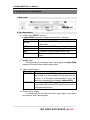
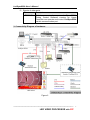
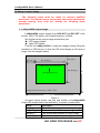
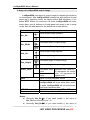
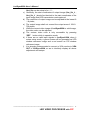
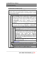
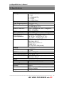
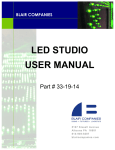
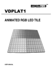
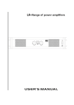
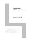
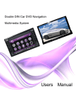
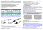
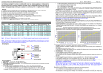
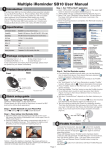
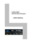
LedSync822A LED Video Processor With PIP USER’S MANUAL LedSync822A User’s Manual TABLE OF CONTENTS I. Safety precautions ----------------------------------------------------------------- 3 II. Connections of hardware 1.Rear view ------------------------------------------------------------ 4 2. Port description --------------------------------------------------------------------- 4 3. Connectivity Diagram of hardware------------------------------------------ 6 III. Frontal panel operations 1. Diagram of frontal panel---------------------------------------------------------- 7 2. Button operations -------------------------------------------------------- 7 3. Software control--------------------------------------------------------------------- 8 IV. Output image setup 1. LedSync822A output image----------------------------------------------------- 9 2. Setup LedSync822A output image ------------------------------------------ 10 V. Troubleshooting ------------------------------------------------------------------ 12 VI. Specifications----------------------------------------------------------------------- 15 --------------------------------------------------------------------------------------------------LED VIDEO PROCESSOR with PIP 2 LedSync822A User’s Manual I. Safety Precautions Danger! There is high voltage in the processor, to prevent any unexpected hazard, unless you are a maintenance, please do not open the cover of the device. Warning! 1. This device shall not encounter water sprinkle or splash, please do not place anything containing water on this device. 2. To prevent fire, keep this device far from any fire source. 3. To keep good ventilation, there shall be at least 20cm interval between frontal and rear panel of the device. 4. If this device gives out any strange noise, smoke or smell, please immediately unplug the power cord from receptacle, and contact local dealer. 5. Please do not plug or unplug DVI signal cable when the device on power. Caution! 1. Please thoroughly read this manual before using this device, and keep it well for future reference. 2. In the event of lighting or when you are not going to use the device for a long time, please pull the power plug out of receptacle. 3. Nobody other than professional technicians can operate the device, unless they have been appropriately trained or under guidance of technicians. 4. To prevent equipment damage or electric shock, please don’t fill in anything in the vent of the device. 5. Do not place the device near any water source or anywhere damp. 6. Do not place the device near any radiator or anywhere under high temperature. 7. To prevent rupture or damage of power cords, please handle and keep them properly. 8. Please immediately unplug power cord and have the device repaired, when 1) Liquid splashes to the device. 2) The device is dropped down or cabinet is damaged. 3) Obvious malpractice is found or performance degrades. --------------------------------------------------------------------------------------------------LED VIDEO PROCESSOR with PIP 3 LedSync822A User’s Manual II. Connections of hardware 1. Rear view Figure 1 2. Port description 1) Video input (INPUT column) LedSync822A supports 8-channel signal input, including: Port name Description 4-channel PAL/NTSC system composite V1~V4 video input 1-channel PAL/NTSC system S_Video input Y/C (S_Video) 1-channel computer analog signal input VGA 1-channel computer digital signal input DVI 1-channel high-definition component signal YPbPr input 2) Audio input Corresponding to 8-channel video input signal, LedSync822A supports 8-channel stereo audio signal input 3) Video signal output Port name Description VGA OUT 1-channel analog RGBHV signal output, it can be connected to a local display device and used as monitor (it is strongly recommended to use this port when operating and setting LedSync822A). DVI OUT 1-channel digital DVI signal output, it is to be connected with external LED transmission card or LED transmission box 4) Audio signal output It corresponds to the selected video input signal, and output this channel audio input signals. --------------------------------------------------------------------------------------------------LED VIDEO PROCESSOR with PIP 4 LedSync822A User’s Manual 5) Signals of other ports Port name Description RS232 IN Serial communication port, LedSync822A’s Timing Control Software running on Upper Controller can operate and control LedSync822A via this communication port. 3. Connectivity Diagram of hardware: Figure 2 --------------------------------------------------------------------------------------------------LED VIDEO PROCESSOR with PIP 5 LedSync822A User’s Manual III. Frontal panel operations 1. Diagram of frontal panel Figure 3 2、 Button operations: LedSync822A have 14 buttons on frontal panel, after start-up all these buttons are in operation mode. Their functions are described as below: 1) Select input video source Button names Description Switch to V1~V4, composite video input V1~V4 Y/C (S_Video) Switch to S-Video input Switch to computer analog signa input VGA Note: to get clarity computer image, you can click the “VGA” button 6 times continuously, and then you can click “VGA” button again and again to change the computer image sampling phase, when the computer image be displayed most clearly, the adjustment is ok. Switch to computer digital signal input DVI Switch to high-definition component video signal YPbPr input Note: to get clarity HDTV image, you can click the “YPbPr” button 6 times continuously, and then you can click “YPbPr” button again and again to change the HDTV image sampling phase, when the HDTV image be displayed most clearly, the adjustment is ok. Switch audio input while operating above buttons, select the audio signal input from corresponding video input to output it through Audio OUT. Notes: when user has selected input signal, if there are signal input in corresponding signal input ports and are in LedSync822A formats, the indicator above corresponding button will be illumed. However, when there are no signal input in corresponding input ports, the indicator above corresponding button will blink, and dark screen will be displayed on the screen. --------------------------------------------------------------------------------------------------- 6 LED VIDEO PROCESSOR with PIP LedSync822A User’s Manual 2) Select output brightness Button names Description Decrease output BRT LedSync822A Increase output BRT + LedSync822A image brightness of image brightness of LedSync822A supports 8 levels Brightness, “1” represents the lowest brightness, 8 represents the highest brightness. When brightness is adjusted to be “1”, ”3”, ”5” or “7”, their LED indicators will blink; When brightness is adjusted to be “1”, ”3”, ”5” or “7”, their LED indicators will keep illumed. 3) Select image status Button names Description Select user-defined image parameters, including DEF GAMMA value, Video Chrom and Hue. Select a standard image status to output image. STD This standard image has been preset at factory, including GAMMA =1, Video Chrom and Video Hue = standard values. User can’t modify these standard values. 4) Select FULL/PART display (VD/PIP,PC/ZOOM) Button names Description Switch the video display mode, when the VD/PIP indicator above this button be extinguished, the video will be displayed with PIP mode, on the contrary, the video will be displayed on the whole LED screen Switch the VGA/DVI display mode , when the PC/ZOOM indicator above this button be extinguished, VGA/DVI input image will be shrinked onto the whole LED screen; when the indicator be illumed, VGA/DVI input image will be displayed partly without shrink; and when the indicator blink, VGA/DVI input image will be output fully without shrink. --------------------------------------------------------------------------------------------------LED VIDEO PROCESSOR with PIP 7 LedSync822A User’s Manual 3、 Software Control: LedSync822A is supplied with Timing Control software , user can operate and control LedSync822A using this software, including: z Switch input signal source, change brightness of output images. z Manually operate and control it or edit operation and control schedule to make it executed automatically. z Carry out site control, or remote control over LAN or WAN. For details please refer to LedSync82xx Timing Control. --------------------------------------------------------------------------------------------------LED VIDEO PROCESSOR with PIP 8 LedSync822A User’s Manual IV. Setup of output image The following setps must be made by relevant qualified technicians. For ordinary users, unless they have received adequate relevant training, they shall not attempt the following setup operations! 1. LedSync822A output image LedSync822A output images from VGA OUT and DVI OUT in the format: 1024×768 pixels, with refresh frequency of 60Hz. We should set two output image window,they are: LED image window Video PIP window First,We set LedSync822A to output the images exactly fitting the resolution of LED screen, so that the LED could display a full frame of image. See the diagram below: (0,0) Hor_Str_L Hor_Width_L Vert_Str_L LedSync822A Out Image Area 768 Vert_Height_L LED Dispaly Screen LedSync822A Out Format = 1024×768 1024 Figure 4 As above figure shows: the size and location of LedSync822A output LED image window are defined by 4 groups of parameters: Name Description Hor_Str_L The horizontal start position of output image Hor_Width_L The horizontal width of output image Vert_Str_L The vertical start position of output image Vert_Height_L The vertical height of output image --------------------------------------------------------------------------------------------------- 9 LED VIDEO PROCESSOR with PIP LedSync822A User’s Manual Video PIP window should be set to located in the LED image window, as the diagram below shows: (0,0) Hor_Str_P Hor_Width_P Vert_Height_P 768 PIP Window Vert_Str_P LED Dispaly Screen LedSync822A Out Format = 1024×768 1024 Figure 5 As above figure shows: the size and location of LedSync822A output PIP window are defined by 4 groups of parameters: Name Description Hor_Str_P The horizontal start position of output image Hor_Width_P The horizontal width of output image Vert_Str_P The vertical start position of output image Vert_Height_P The vertical height of output image The start coordinates (0, 0) of sync820C output image is defined in the right top of 1024×768 pixels output area. --------------------------------------------------------------------------------------------------LED VIDEO PROCESSOR with PIP 10 LedSync822A User’s Manual 2. Setup of LedSync822A output image LedSync822A can setup its output image by operating the buttons on frontal panel. After LedSync822A is started up, all buttons on frontal panel are in operation mode. As above section III.2 describes, if you press “STD” button for continuous 18 times, LedSync822A will enter setup state, and all buttons on frontal panel are ready to be in setup mode. See the table below for the definitions of each button: Name Description Move output image leftward. Hor_Str Move output image rightward. Decrease width of output image Hor_Width Increase width of output image Move output image upward. Vert_Str Move output image downward. Decrease height of output image Vert_Height Increase height of output image Video_Color + Save Setup LED/PIP Step Decrease video Standard color value=0. 16 represents the lowest color Increase video color, +16 represents the highest color color Save currently adjusted values Press the button for continuous 18 times, LedSync822A will enter setup state, press it again, LedSync822A will exit setup state and enter operation state. Switch the setup window, LED or PIP Select step value 1 or 10 Notes: a) Generally Hor_Str≥0. If you need modify it, the value of Hor_Str can be setup to be – 8 ; b) Generally Vert_Str≥0. If you need modify it, the value of --------------------------------------------------------------------------------------------------LED VIDEO PROCESSOR with PIP 11 LedSync822A User’s Manual c) d) e) f) g) h) i) Vert_Str can be setup to be – 5 ; Generally, the start coordinates of output image (Hor_Str_L , Vert_Str_L ) should be identical to the start coordinates of the input image that LED transmission card captured; The resolution of output image can be adjusted to the lowest 8 ×8 pixels; The output image shall not exceed the output area of 1024× 768 pixels; While the current video image of LedSync822A is valid image, the video color can be adjusted; The custom video color is only accessible by pressing “DEF“ button while in operation mode; If there are no valid input signals in LedSync822A, when it enters setup mode, a green screen will be generated as LED window reference image and a red screen as PIP window reference image; It is strongly recommended to connect a VGA monitor to VGA OUT of LedSync822A, so as to intuitively display all above adjustment and setups. --------------------------------------------------------------------------------------------------LED VIDEO PROCESSOR with PIP 12 LedSync822A User’s Manual V. Troubleshooting 1、 Dark screen, no image on LED Check the input source of LedSync822A for any abnormality. If the indicator above input signal button is illumed, it means the input source is in good condition; however, if the indicator blinks, it means some fault has occurred. If the input source is normal, the indicator will keep illumed. Press “PC/ZOOM“ button on frontal panel of LedSync822A. When the indicator blink, LED will display image; however, the indicator be illumed, LED will display dark screen; the moment please check whether the start coordinates of LedSync822A output image is identical to the start coordinates of the input image that LED transmission card captured. No image display even when PC/ZOOM’s indicator blink, connect one VGA monitor to VGA OUT of LedSync822A, check whether there are images appearing on VGA monitor. If there are images on VGA monitor,please check: The DVI connection between DVI output of LedSync822A and DVI input of LED transmission card Each section of Ethernet cable connection between LED transmission card and LED screen. The signal has been weakened a lot and imposed high risk of interference from outside after long-term transmission passing many sections of Ethernet cable. Please adopt high-quality Ethernet cable and RJ45 connector, and shorten the Ethernet cable to the most extent. Hot swap of DVI cable may result in burning of DVI drive or receiving chips. If there are no images on VGA monitor, please have supplier repair it If the input source is abnormal, the indicator will keep blink. If current input source is: DVI First, check DVI connection cable Actuate DVI output of PC graphic display card --------------------------------------------------------------------------------------------------LED VIDEO PROCESSOR with PIP 13 LedSync822A User’s Manual Set the output resolution any of the following 800×600 1024×768 1280×1024 Note that DVI output refresh frequency (Vertical Scanning Frequency) must be: 60Hz If DVI indicator of LedSync822A frontal panel still blinks, please have supplier repair it. If current input source is: VGA First, check VGA connection cable Actuate VGA output of PC graphic display card Set the output definition any of the following 800×600 1024×768 1280×1024 Note that VGA output refresh frequency (Vertical Scanning Frequency) must be: 60Hz If VGA indicator of LedSync822A frontal panel still blinks, please have supplier repair it. If current input source is: YPbPr First, check YPbPr cable, the three cables Y, Pb, Pr are connected to corresponding input jacks of LedSync822A respectively. Make sure YPbPr signal is in any of the following formats: 720p@60Hz 1080i@60Hz If the YPbPr indicator on frontal panel of LedSync822A still blinks, please have supplier repair it. If current input source is: Y/C(S_Video) Check S_Video cable. Make sure S_Video output of DVD player has been actuated (some DVD players might have disabled S_Video output, it must be reset and actuated). If Y/C indicator on frontal panel of LedSync822A still blinks, please have supplier repair it --------------------------------------------------------------------------------------------------LED VIDEO PROCESSOR with PIP 14 LedSync822A User’s Manual 2、 Timing Control software can’t control LedSync822A 1) Make sure RS232 cable supplied with the machine is properly connected, one end connects COM port of PC, the other end connects RS232 IN of LedSync822A; 2) Identify the No. of the PC’s COM port to be connected, e.g. COM1 or COM2, select appropriate COM port on control software; 3) Select appropriate COM port, and ensure this COM port not yet occupied by other applications, e.g. the common LedStudio software; 4) If after the above steps LedSync822A still can’t be controlled, please have supplier repair it. --------------------------------------------------------------------------------------------------LED VIDEO PROCESSOR with PIP 15 LedSync822A User’s Manual VI. Specifications Inputs Nums/Type 1×RGBHV(VGA) 1×DVI 1×YPbPr(HDTV) 4×CVBS 1×Y/C(S-Video) Video system PAL/NTSC CVBS Scope/Impedance 1V (p_p) / 75Ω Y/C Scope/Impedance Y: 0.7V (p_p) / 75Ω, C: 0.35V (p_p) / 75Ω RGB/DVI resolution 1280×1024@60Hz, 1024×768@60Hz , 800×600@60Hz RGB Scope/Impedance 0.7 V (p_p) / 75Ω YPbPr (HDTV) System 1280×720p@60Hz, 1920×1080i@60Hz YPbPr (HDTV) Y: -0.3V ~ +0.7V (p_p) / 75Ω Scope/Impedance Pb: -0.35V ~ +0.35V (p_p) / 75Ω Pr: -0.35V ~ +0.35V (p_p) / 75Ω Connectors RGBHV: 15pin D_Sub(female) DVI: 24+1 DVI_D YPbPr(HDTV): RCA×3 CVBS: RCA Y/C: 4pin mini DIN(female) Outputs Nums/Type 1×RGBHV 1×DVI RGB/DVI resolution 1024×768@60Hz RGB Scope/Impedance 0.7 V (p_p) / 75Ω Connectors RGBHV: 15pin D_Sub(female) DVI: 24+1 DVI_D Others Control RS 232. Panel Button Power 100-240VAC 60W 50/60Hz 5-40 ℃ Operating Temp 15-85% Humidity Size 155 mm (high) ×350mm (wide) × 485mm (length) 5.6 Kg Weight --------------------------------------------------------------------------------------------------LED VIDEO PROCESSOR with PIP 16