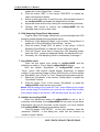
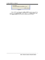
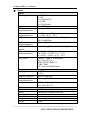
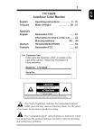
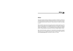
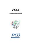
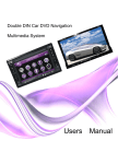
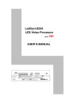
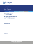
1
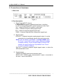
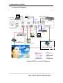
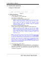
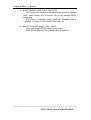
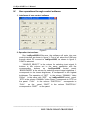
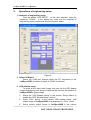
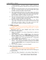
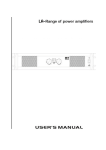
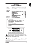
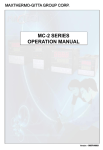
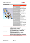
LedSync820B
LED Video Image Processor
USER’S MANUAL
LedSync820B User’s Manual
I.
Safety Precautions
Danger!
There is high voltage in the processor, to prevent any unexpected
hazard, unless you are a maintenance, please do not open the cover of the
device.
Warning!
1. This device shall not encounter water sprinkle or splash, please do not
place anything containing water on this device.
2. To prevent fire, keep this device far from any fire source.
3. To keep good ventilation, there shall be at least 20cm interval between
frontal and rear panel of the device.
4. If this device gives out any strange noise, smoke or smell, please
immediately unplug the power cord from receptacle, and contact local
dealer.
5. Please do not plug or unplug any signal cable when the device
on power.
Caution!
1. Please thoroughly read this manual before using this device, and keep
it well for future reference.
2. In the event of lighting or when you are not going to use the device for
a long time, please pull the power plug out of receptacle.
3. Nobody other than professional technicians can operate the device,
unless they have been appropriately trained or under guidance of
technicians.
4. To prevent equipment damage or electric shock, please don’t fill in
anything in the vent of the device.
5. Do not place the device near any water source or anywhere damp.
6. Do not place the device near any radiator or anywhere under high
temperature.
7. To prevent rupture or damage of power cords, please handle and keep
them well.
8. Please immediately unplug power cord and have the device repaired,
when
1) Liquid splashes to the device.
2) The device is dropped down or cabinet is damaged.
3) Obvious malpractice is found or performance degrades.
---------------------------------------------------------------------------------------------------
LED VIDEO IMAGE PROCESSOR
2
LedSync820B User’s Manual
II. Connections of hardware
1. Rear view
Figure 1
2. Port description
1) Signal input (INPUT column)
LedSync820B supports 8-channel signal input, including:
V1~V4: 4-channel PAL/NTSC system compound video input
Y/C: 1-channel PAL/NTSC system s-video input
VGA: 1-channel computer analog signal input
DVI: 1-channel computer digital signal input
YPbPr: 1-channel high-definition component signal input
2) Signal output
VGA OUT: 1-channel computer analog signal output, it can be
connected to a local display device and used as monitor
Notes: with the default “SyncMode” of LedSync820B output
as “Force ”,some VGA monitor maybe display flickerlingly
or display nothing. To get a steady image on these VGA
monitor,you must change the “SyncMode” from “Force”
to “Free” by RS232 software.
DVI OUT: 1-channel computer digital signal output, to drive the
LED transmission card
3) Control signal
RS232 IN: RS232 serial communication input
RS232 OUT: RS232 serial communication output, connected to
the next device with RS232
---------------------------------------------------------------------------------------------------
LED VIDEO IMAGE PROCESSOR
3
LedSync820B User’s Manual
3. Connectivity Diagram:
RS232
YPbPr(1080I/720P)
Laptop PC
(LedSync820B Setup)
Camera
CVBS
LedSync820B
DVI
S-Video
VGA
VGA
HD DVD
DVI
OR
DVD
Ethernet Transmitter
PC
Ethernet
Transmitter Card
Laptop
Monitor
If Ethernet Transmitter Card
Inside of LedSync820B
DVI
RS232
VGA
YPbPr
CVBS/S-Video
Ethernet
LED
LedSync820B Connectivity Diagram
---------------------------------------------------------------------------------------------------
LED VIDEO IMAGE PROCESSOR
4
LedSync820B User’s Manual
III. Frontal panel operations
1. Diagram of frontal panel
Figure 2
2、 Button operations:
1) Select input video source
V1~V4: switch to V1~V4 CVBS input
Y/C: switch to s-video input
VGA: switch to computer analog signa input
Notes: to get clarity computer image, you can click the “VGA”
button 6 times continuously, and then you can click “VGA”
button again and again to change the computer image
sampling phase, when the computer image be displayed
claritily, the adjustment is ok
DVI: switch to computer digital signal input
YPbPr: switch to high-definition component video signal input
Notes: to get clarity HDTV image, you can click the “YPbPr”
button 6 times continuously, and then you can click “YPbPr”
button again and again to change the HDTV image sampling
phase, when the HDTV image be displayed claritily, the
adjustment is ok
Notes: when user has selected input signal, if there are signal input
in corresponding signal input ports and are in LedSync820B
formats, the indicator above corresponding button will be illumed.
However, when there are no signal input in corresponding input
ports or are not in the format that LedSync820B supports, the
indicator above corresponding button will blink, and black will be
displayed on the LED screen.
2) Select Brightness (BRT-, BRT+)
LedSync820B supports 8 levels Brightness, 1 corresponds to
the lowest brightness, 8 corresponds to the highest brightness.
Click the button ”Brt-“ will decrease the brightness, and “Brt+” will
increase the brightness.
---------------------------------------------------------------------------------------------------
LED VIDEO IMAGE PROCESSOR
5
LedSync820B User’s Manual
3) Select GAMMA / Video Chrom (DEF, STD)
DEF select user-defined image parameters,including GAMMA
value, Video Chrom and Hue,which can be set through RS232
control port.
STD select a standard image status as GAMMA fixed at
GAMMA =1,Video Chrom=32 and Video Hue=32.
4) Select FULL/PART display (FULL, PART)
FULL means that LED will display a full picture.
PART means that LED only display a part of a picture.
---------------------------------------------------------------------------------------------------
LED VIDEO IMAGE PROCESSOR
6
LedSync820B User’s Manual
IV.
User operations through control software
1. Interfaces of user control software
Figure 3
2. Operation Instructions
Run LedSync820Bv203en.exe, the software will enter into user
control interface as shown in figure 3. First of all, select the COM port
through which PC conncet to LedSync820B, as shown in figure 3,
COM1 is selected.
“SOURCE_SELECT” is the column for selecting input signal, 8
buttons in this column act in the same operations with the
corresponding
buttons
on
LedSync820B
frontal
panel;
“BRIGHTNESS” is the column for selecting output image brightness. 1
corresponds to the lowest brightness, 8 corresponds to the highest
brightness; The operation of “DEF” in the column “GAMMA / Video
Chrom” is the same with “DEF” on LedSync820B frontal panel;
“STD” in the column “GAMMA / Video Chrom” corresponds to “STD” on
the panel. “FULL” in the column “PART/FULL” corresponds to
“FULL”
on the
panel, “PART” in the column “PART/FULL”
corresponds to “PART” on the panel.
---------------------------------------------------------------------------------------------------
LED VIDEO IMAGE PROCESSOR
7
LedSync820B User’s Manual
V.
Operations of engineering setup
1. Interfaces of engineering setup
Click the button “LED SETUP” on the user interface, enter the
password “123456” in the dialog box, enter into the interface of
engineering setup interface as shown in figure 4 below:
Figure 4
2. Select COM port
Select the COM port through which the PC connected to the
LedSync820B, as shown in figure 4, COM1 is selected.
3. LED window setup
To scale all the input video image just onto the the LED display
screen,engineering user should customize the size and the location of
LedSync820B’s output image.
1) Select the “LED Window Setup” in the column “Setup Select” to
enable the “LED Window Setup” column.
2) Press “FULL” button in the column “LED window setup”, shift
output image of LedSync820B to be displayed in “FULL” mode.
3) Select current output format of LedSync820B in the column
---------------------------------------------------------------------------------------------------
LED VIDEO IMAGE PROCESSOR
8
LedSync820B User’s Manual
4)
5)
6)
7)
“ Output Resolution” , as shown in figure 4, “XGA” is selected. At
the same time,this operation read back the LED window’s size and
location.
Enter the horizontal start location of the output image in the column
“Hori_Str” , as shown in figure 4, the value is set to be “200”, press
the button “saving” in its right to save the value.
Enter the horizontal width value of the output image in the column
“Hori_Width”. Generally ,this value equal to the horizontal pixels of
the LED screen. as shown in figure 4, the value is set to be “400”.
press the button “saving” in its right to save the value.
Enter the vertical start location of the output image in the column
“Vert_Str” , as shown in figure 4, the value is set to be “100”, press
the button “saving” in its right to save the value.
Enter the vertical heigh of the output image in the column
“Vert_Heigh”. Generally ,this value equal to the vertical lines of the
LED screen, as shown in figure 4, the value is set to be “300”.
press the button “saving” in its right to save the value.
4. GAMMA value setup
LedSync820B has been set with default GAMMA values at factory,
as GAMMA=1, unless otherwise set by engineering users, no need to
change the default setup!
Engineering users can define GAMMA values within 0.4~3.99
following the procedures below:
1) Select the “GAMMA” in the column “Setup Select” to enable the
“GAMMA” column.
2) Select “DEF” in the column “GAMMA Setup”, the moment the
previous GAMMA vlaue in the LedSync820B will be read back.
After the reading, we can enter a new desired GAMMA value in the
column “GAMMA Value”, If the value entered is 120 , it means that
actual GAMMA value is 120/100=1.2.
3) Click the button “Saving”, the prompt column will show “Please
waiting…”, the moment control software is writing the new GAMMA
value into LedSync820B, when it is completed, the prompt column
will show “ok”.
4) STD is fixed at GAMMA=1, no one can change it.
5. Video Chrom/Hue Adjustment
LedSync820B has been set to be exfactory standard video status,
generally, it is unnecessary to make the following adjustment!
Engineering users can adjust video chrom and hue following the
procedures below:
1) Select the “Video Chrom/Hue” in the column “Setup Select” to
---------------------------------------------------------------------------------------------------
LED VIDEO IMAGE PROCESSOR
9
LedSync820B User’s Manual
2)
3)
4)
5)
enable the “Video Chrom/Hue ” column.
Click the button “DEF” in the column “DEF/STD” to enable the
video input selection button.
Select a valid video input to read the user_defined datas stored in
the LedSync820B and enable the adjustment scroll bar.
Adjust the chrom and hue by clicking the corresponding scroll bar;
Clicking “Std” button to recover the LedSync820B into the
standard video chrom or hue value.
6. VGA Sampling Phase/Clock Adjustment
To get a clarity VGA image, sometimes, you should adjust the VGA
sampling phase following the procedures below:
1) Select the “VGA Sampling Phase” in the column “Setup Select” to
enable the “VGA iN Sampling Clock/Phase ” column .
2) Click the button “Read VGA iN status” in the column “VGA iN
Sampling Clock/Phase” to read the current VGA input status.
3) Click the “Phase” scroll bar to change the VGA sampling phase,
when the VGA image be displayed claritily, the adjustment is ok.
4) Generally, the VGA sampling clock is unnecessary to change !!
7. Sync Mode select
There are two output sync modes of LedSync820B ,and the
default sync mode is “Force” when LedSync820B at factory.
With the default “SyncMode” of LedSync820B output as
“Force ”,some VGA monitor maybe display flickerlingly or display
nothing. To get a steady image on these VGA monitor,you must change
the “SyncMode” from “Force” to “Free” following the procedures below:
1) Select the “SyncMode” in the column “Setup Select” to enable the
“SyncMode” column .
2) Click the button “Free” in the column “SyncMode” to make the
LedSync820B output as free sync mode.
Notes: With the output sync mode as “Free”, some flickering line maybe
occur on the image.To avoid this,you must set the vertical start location
of the output image in the column “LED window setup” as Vert_Str=0 .
8. Initialize the LedSync820B
When the adjustment datas of LedSync820B be lost or be in
confusion unfortunately, the LedSync820B will not work ok and some
adjustments can not be executed, at the moment, you must initialize
the LedSync820B following the procedures below:
Click the button “LED SETUP” on the user interface, enter the
password “654898” in the dialog box, enter into the interface as
shown in figure 5 below:
---------------------------------------------------------------------------------------------------
LED VIDEO IMAGE PROCESSOR
10
LedSync820B User’s Manual
Figure 5
Click “YES” to initialize the LedSync820B ,and then shut off the
power of the LedSync820B. When power on LedSync820B again,
the LedSync820B will work with the default values at factory.
---------------------------------------------------------------------------------------------------
LED VIDEO IMAGE PROCESSOR
11
LedSync820B User’s Manual
Ⅵ.
Specs
Inputs
Nums/Type
Video system
CVBS
Scope/Inpedence
Y/C
Scope/Inpedence
RGB/DVI resolution
RGB
Scope/Inpedence
YPbPr(HDTV)
System
YPbPr(HDTV)
Scope/Inpedence
Connectors
Outputs
Nums/Type
RGB/DVI resolution
RGB
Scope/Inpedence
Connectors
Others
Control
Power
Operating Temp
Humidity
Size
Weight
1×RGBHV
1×DVI
1×YPbPr(HDTV)
4×CVBS
1×Y/C(S-Video)
PAL/NTSC
1V(p_p)/ 75Ω
Y:0.7V(p_p)/ 75Ω,
C:0.35V(p_p)/ 75Ω
1280×1024@60Hz,1024×768@60Hz ,
800×600@60Hz
0.7 V(p_p)/ 75Ω
1280×720p@60Hz,1920×1080i@60Hz
Y:-0.3V ~ +0.7V(p_p)/ 75Ω
Pb: -0.35V ~ +0.35V(p_p)/ 75Ω
Pr: -0.35V ~ +0.35V(p_p)/ 75Ω
RGBHV:15pin D_Sub(female)
DVI:24+1 DVI_D
YPbPr(HDTV): BNC×3
CVBS:BNC
Y/C:4pin mini DIN(female)
1×RGBHV
1×DVI
1024×768@60Hz
0.7 V(p_p)/ 75Ω
RGBHV:15pin D_Sub(female)
DVI:24+1 DVI_D
RS 232、Panel Button
100-240VAC 50/60Hz 60W max
5-40 ℃
15-85%
60 mm(high)×425mm(wide)×280mm(deep)
4.5 Kg
---------------------------------------------------------------------------------------------------
LED VIDEO IMAGE PROCESSOR
12