1
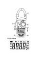
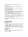
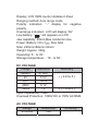
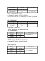
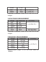
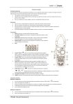
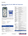
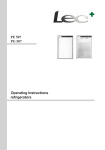
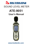
AC/DC CLAMP METER
ACM-2031
USER’S MANUAL
www.tmatlantic.com
CONTENTS
PAGE
SAFETY INFORMATION …………… 1
SYMBOL EXPLANATION …………… 1
SAFETY PRECAUTIONS …………… 2
MAINTENANCE ………………………… 3
GENERAL DESCRIPTION …………… 4
PANEL DESCRIPTION ………………
OPERATING INSTRUCTIONS
4
...……… 7
SPECIFICATIONS ……………………… 12
AUTO
POWER
REPLACING THE
OFF ………………… 16
BATTERY………… 17
ACCESSORIES ………………………… 18
SAFETY INFORMATION
The digital clamp meter has been designed
according to IEC1010 1 and IEC1010 2 032
concerning safety requirements for electrical
measuring instruments and hand-held current
clamps with double insulation overvoltage
category 1000V CAT II 600V CAT III and
pollution 2.
This meter complies with the requirements of the
following European Community Directives:
89 / 336 / EEC (Electromagnetic Compatibility)
and 73 / 23 / EEC (Low Voltage) as amended by
93 / 68 / EEC (CE Marking).
However, electrical noise or intense electromagnetic fields in the vicinity of the equipment may
disturb the measurement circuit.
Measuring instruments will also respond to
unwanted signals that may be present within the
measurement circuit.
Users should exercise care and take appropriate
precautions to avoid misleading.
SYMBOL EXPLANATION
Important safety information, refer to the
operating manual.
Dangerous voltage may be present.
Earth ground.
Double insulation (Protection class 1000V
CAT II 600V CAT III).
SAFETY PRECAUTIONS
Follow all safety and operating instructions to
ensure maximum personal safety during the
operation and to ensure the meter is used safely
and is kept in good operating condition.
Read the operating instructions thoroughly and
completely before operating your meter.
Pay attention to WARNINGS, which will inform
you of potentially dangerous proce-dures. The
instructions in these warnings must be followed.
Always inspect your meter and test leads for
any sign of damage or abnormality before every
use. If any abnormal conditions exist (i.e. broken
test leads, cracked cases, display not reading,
etc.), do not attempt to take any measurements.
Do not expose the instrument to direct sunlight,
extreme temperature or moisture.
Never ground yourself when taking electrical
measurements. Keep your body isolated from
ground by using dry clothing, rubber shoes,
rubber mat or any approved insulating material.
You always are careful when working with
voltages above 60V dc or 30V ac rms. Keep
fingers behind the probe barriers while
measuring.
To avoid damages to the instrument, do not
exceed the maximum limits of the input values
shown in the technical specification tables.
Never use the meter to measure voltages that
might exceed the maximum allowable input value
of any function.
MAINTENANCE
1. Never touch exposed wiring, connections or
any live circuit when attempting to take
measurements.
2. Before opening the case, always disconnect
test leads from all energized circuits.
3. Never use the meter unless the back cover is
in place and fastened completely.
4. Do not use abrasives or solvents on the meter.
To clean it using a damp cloth and mild detergent
only.
5. Qualified and trained service technicians
should only perform calibration and repair of the
meter.
GENERAL DESCRIPTION
The meter is an autorange professional AC/DC
clamp meter with 3999 counts. For measuring
DC and AC voltage, DC and AC current,
Resistance,Capacitance,Temperature,Frequency,
Frequency from the clamp , Duty Cycle, Diode
and Continuity Test with battery operated.
PANEL DESCRIPTION
1.Transformer jaws
Pick up DC or AC current flowing through the
conductor.
2.Rotary switch
Rotary switch is used to select functions.
3.HOLD button
When this button is pushed, the display will keep
the last reading and “ ” symbol will appear on
the LCD. Pushing it again returns the meter to
normal mode.
4.Hz/DUTY button
the button is used to select frequency or duty
cycle measurement in Hz range.
5.LCD display
6.“V:Hzഒ ” Jack
This is positive input terminal for volt, diode,
resistance,capacitance,frequency,dutycycle ,Con
tinuity and temperature measurement.
connection is made to it using the red test lead.
7.“COM” jack
This is negative (ground) input terminal for all
measurements except current.
Connection is made to it using the black test lead.
8.ZERO button
Push the button to get relative measurement
mode, “' ZERO ” annunciate display on LCD. But
store the displayed reading as a reference value.
In the Relative mode, the value shown on the
LCD is always the difference between the stored
reference value and the present reading. If the
new reading is the same as the reference value,
the display will be zero.
9.FUNC. button
In :
range, push the button to select
or
or
function. Different symbol
: or
of function and measurement unit will appear on
the LCD. In current range, press this button to
select AC current or DC current.
10.Power Switch
A push push switch is used to turn the meter on
or off
11.Rigger
Press the lever to open the transformer. When
the lever is released, the jaws will close again.
OPERATING INSTRUCTIONS
DC VOLTAGE MEASUREMENT
1. Insert the black and red test leads into the COM
and V: Hz
input terminals respectively.
2. Set rotary switch at desired V
position.
Connect the test lead tips in parallel with the
circuit to be measured. Be careful not to touch
any electrical conductors. The polarity of the red
lead connection will be indicated along with the
voltage value.
3. Read the measure result from the display.
AC VOLTAGE MEASUREMENT
1. Insert the black and red test leads into the
COM andV:Hz
input terminals respectively.
2. Set rotary switch at desired V~ position.
Connect the test lead tips in parallel with the
circuit to be measured. Be careful not to touch
any electrical conductors.
3. Read the measure result from the display.
4.When measuring AC voltage, pushing
Hz/DUTY button, the frequency of ACV will
show on LCD display.
DC CURRENT MEASUREMENT
1. Set the rotary switch at desired 400A or 1000A
position.
2. Push the FUNC. button to select DC current.
3.Push the “ ZERO ” button to get relative
measurement mode and “0000” show on LCD
display.
4. Press the trigger to open transformer jaw and to
clamp one conductor only, making sure that the
jaw is firmly closed around the conductor.
5. Read current value on LCD display.
NOTE: As the jaw core may remain some
magnetic force after using for awhile. If the
display can not reach “0”, open the jaws
several times. Then work again.
AC CURRENT MEASUREMENT
1. Set the rotary switch at desired 400A or 1000A
position.
2. Push the FUNC. button to select AC current.
3. Press the trigger to open transformer jaw and to
clamp one conductor only, making sure that the
jaw is firmly closed around the conductor.
4. Read current value on LCD display.
RESISTANCE MEASUREMENT
1. Insert the black and red test leads into the
COM andV:Hz
input terminals respectively.
2.Set rotary switch at desired :
range
position.
3. Push FUNC. button to select :.
4.If the resistance being measured exceeds the
maximum value of the range or the input is not
connected, an overrange indication “OL” will be
display.
5.Read the measure result directly from LCD
display.
NOTE:When checking in-circuit resistance, be
sure the circuit under test has all power
removed and that all capacitors have been
discharged fully.
CONTINUITY TESTING
1. Insert the black and red test leads into the
COM andV:Hz
input terminals respectively.
2.Set rotary switch at desired :
range
position. Push FUNC. button to select
.
3.If continuity exists (i.e., resistance less than
30:) built – in buzzer will sound.
DIODE MEASUREMENT
1. Insert the black and red test leads into the
COM andV:Hz
input terminals respectively.
2.Set rotary switch at desired :
range
position. Push FUNC. button to select
.
3.The red lead should be connected to the anode
and the black lead to the cathode of the diode.
4.The typical voltage drop should be about 0.6V
for silicon diode or 0.3V for germanium diode.
5.If the diode is reverse biased or there is an
open circuit the reading displayed will be “OL”.
CAPACITANCE MEASUREMENT
1. Insert the black and red test leads into the
COM andV:Hz
input terminals respectively.
2.Set rotary switch at desired :
range
position. Push FUNC. button to select
.
3. Connect test leads across the capacitor under
measurement and be sure that the polarity of
connection is observed (Note: The polarity of the
red lead connection is positive “+”).
4.Read the measure result directly from the
display.
MEASURING FREQUENCY
1. Insert the black and red test leads into the
COM andV:Hz
input terminals respectively.
2.Set rotary switch at desired Hz position, Push
Hz/Duty button to select frequency mode and
connect the test lead tips in parallel with the
circuit to be measured. Be careful not to touch
any electrical conductors.
3.The signal amplitude must also be greater than
the sensitivity level.
4.Determine that the amplitude level of the signal
to be measured is not greater than the input
voltage limit (25V DC/AC rms.).
5.Read the measure result directly from LCD
display.
NOTE᧶The input voltage should be between 1V
and 10V rms. ac. If the voltage is more than 10V
rms. Reading may be out of the accuracy range.
MEASURING FREQUENCY FOR CLAMP
1. Set the rotary switch to
position.
2. Press the trigger to open transformer jaw and
to clamp one conductor only, making sure that
the jaw is firmly closed around the conductor.
3. Read the measure result of frequency of AC
current flowing through the transformer jaw
from the display.
NOTE:
Frequency range: 40Hz to 400Hz ( > 20A ).
MEASURING TEMPERATURE
1. Set the rotary switch at qC Position. The LCD
display will show “OL”.
2. Connect the red lead of“K” type thermocouple
into the“V:Hz
”jack and the black lead of“K”
type thermocouple into the “COM” jack. The LCD
display will show the current environment
temperature.
3. Contacting the object be measured with the
thermocouple probe.
4. Read temperature value on the LCD display.ᇭ
DUTY CYCLE TEST
1. Insert the black and red test leads into the
COM andV:Hz
input terminals respectively.
2. Set rotary switch at desired Hz position.
Push Hz/Duty button to select % mode and
connect the test lead tips in parallel with the
circuit to be measured. Be careful not to touch
any electrical conductors.
3.Read the measure result directly from LCD
display.
SPECIFICATIONS
Accuracy:
±% of reading ±number of least significant digits
at 18ഒ to 28ഒ, with relative humidity up to 75%.
All specifications assume less than 1 year since
calibration. Temperature coefficient:0.1×specified
accuracy/ ഒᇭ
GENERA
Maximum voltage: 1000V DC or 700V AC RMS
Altitude: <2000m
Display: LCD 3999 counts Updates 2-3/sec
Ranging method: Auto range mode
Polarity indication: “” display for negative
polarity
Overrange indication: LCD will display “OL”
Low battery: “
” will appears on LCD
Jaw capability: 40mm,Max conductor size
Power: Battery1.5Vu3
Size AAA
Size: 225mm×86mm×32mm
Weight: Approx. 330g
Operating: 5 to 35
Storage temperature: 10 to 50
DC VOLTAGE
Range
Resolution
Accuracy
400mV
0.1mV
r᧤0.8%+5᧥
4V
1mV
40V
10mV
400V
0.1V
1000V
1V
r᧤1.0%+5᧥
Input Impedance: 10M:
Overload Protection: 1000V DC or 700V AC RMS
AC VOLTAGE
Range
4V/50Hz
Resolution
1mV
Accuracy
40V/50Hz
10mV
r᧤1.2%+5᧥
400V/50Hz
0.1V
700V/50Hz
1V
r᧤1.5%+5᧥
Input Impedance: 10M:
Frequency range: 40Hz to 400Hz.
Overload Protection: 1000V DC or 700V AC RMS
DC CURRENT
Range
Resolution
Accuracy
400A
0.1A
r᧤3.0%+5᧥
1000A
1A
Overload Protection:
120% ranges for 60 seconds max.
AC CURRENT
Range
Resolution
Accuracy
r᧤3.0%+8᧥
400A
0.1A
1000A
1A
Overload Protection:
120% ranges for 60 seconds max.
Frequency range: 50Hz to 60Hz.
RESISTANCE
Range
Resolution
400:
0.1:
4k:
1:
40k:
10:
Accuracy
r᧤1.0%+5᧥
400k:
0.1k:
4M:
1k:
r᧤1.0%+5᧥
40M:
10k:
r᧤2.0%+5᧥
Overload Protection: 250V dc or rms. ac for all
ranges.
CAPACITANCE MEASUREMENT
Range
Resolution
Accuracy
4nF
1pF
r᧤4.0%+10᧥
40nF
10pF
400nF
0.1nF
4uF
1nF
40uF
10nF
Not Specified
Overload Protection: 250V dc or rms. ac for all
ranges.
FREQUENCY MEASUREMENT
Range
Resolution
Accuracy
40Hz
0.01Hz
400Hz
0.1Hz
r᧤0.1%+1᧥
4kHz
1Hz
40kHz
10Hz
100kHz
0.1kHz
Measurement range: 1V to 10V rms. 10Hz to
100kHz.
FREQUENCY MEASUREMENT FOR CLAMP
Range
Resolution
Accuracy
r᧤0.1%+1᧥
40Hz
0.01Hz
400Hz
0.1Hz
Measurement range: 40Hz~400Hz / >20Aᇭ
TEMPERATURE
Range
400ഒ~750ഒ
0ഒ~400ഒ
-40ഒ~0ഒ
Resolution
1ഒ
1ഒ
1ഒ
Accuracy
r᧤1.0%+5᧥
r᧤1.0%+3᧥
r᧤1.0%+6᧥
AUDIBLE CONTINUITY AND DIODE
Range
Description
If continuity exists (about less than
30:), built-in buzzer will sound.
Show the approx. Forward voltage of
the diode.
Duty cycle: 0.1% to 99.9%
AUTO POWER OFF
To extend the battery life, Auto Power Off
function is provided. If no key operations of range
changing happen about 15 minutes, the meter
will be turned off automatically. To turn it on,
rotate the rotary switch or push any function
buttons only.
REPLACING THE BATTERY
WARNING
To avoid electrical shock or
personal injury, remove the test
leads and any input signals before
replacing the battery. Replace only
with same type of battery.
When the electrical tester displays the “
”
mark or the backlight be not very lit, the battery
must be replaced to maintain proper operation.
Use the following procedure to replacing the
battery:
1. The Rotary Switch is used to select OFF.
Disconnect test leads from any live source and
remove the test leads from the input terminals.
2. Remove screws on the battery cover and
open the cover.
3. Remove the exhausted battery and replace
with three new 1.5V size AAA batteries.
4. Place battery cover and secure by a screw.
CAUTION
this
appliance
in
an
Using
environment with a strong radiated
radio-frequency
electromagnetic
field (approximately 3V/m) may
influence its measuring accuracy.
ACCESSORIES
x Operator’s instruction manual
x test leads
x Gift box
x Battery 1.5Vu3
Size AAA
x “K” type thermocouple