1
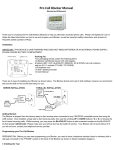
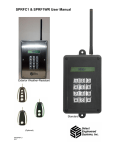
RETURN FOR REPAIR POLICY Every effort has been made to provide reliable, superior quality products. However, in the event your instrument requires repair, forward unit to Service Center freight prepaid to the address below with return address, phone number and/or email address. Service Center 2651 W 81st Street Hialeah, FL 33016 800-222-0956 WARRANTY POLICY The ATD5491 Electrical System Analyzer is warranted to be free of defects in materials and workmanship for a period of two years from the date of purchase. This warranty applies to all repairable instruments that have not been tampered with or damaged through improper use including unauthorized opening of the unit. Please ship warranty units that require repair freight prepaid to Service Center along with proof of purchase, return address, phone number and/or email address. ATD5491 Battery & Electrical System Analyzer For Testing 6V & 12V Vehicle Batteries individually & in Battery Packs. Also for testing 6V, 12V, 24V and 36V Charging & Starter Systems User Manual INTRODUCTION REPLACEMENT PARTS The ATD5491 tests all 6V and 12V all lead acid batteries individually or in parallel and series battery packs. The tester will display the battery or battery pack condition as % available capacity, rated capacity (i.e. CCA’s), state of charge voltage and good, marginal or replace status. The ATD5491 also tests 12V, 24V and 36V starter and charging systems including starter draw, alternator output (loaded/unloaded), and diode ripple. Item Brass post adapters Carrying case Instruction manual IR to USB cable The ATD5491 features an IR wireless printer output for remote printout of the test results. The test data for the last test performed is stored in the memory and can be reviewed either when connected to a battery, or when disconnected from the battery at a later time. Features: • • • • • • • • • • • • • • • • • • • • Patented conductance technology Displays % of capacity and CCA’s. Tests all 12V lead acid batteries including AGM and Gel IR printer interface for remote printing No conversion tables needed Test batteries from 100 CCA to 3500 CCA (battery pack) Tests 6/12/36V Starting/Charging Systems Tests both series and parallel batteries Tests Alternator Ripple Bad cell is detected and displayed Displays Multiple International Units Tests 6V batteries Custom Header with Company Name, Date and Time Loose lead detection Temperature Compensation RoHS compliant brass post adapters included Multiple language (English, Spanish, French) Reverse polarity protection Auto shutoff feature Made in USA 1 Part Number PRT5491-01 PRT5491-02 PRT5491-03 PRT5491-04 PRODUCT SPECIFICATIONS Model # ATD5491 Micro LCD Name Electrical System Analyzer Battery Size Range 100 CCA to 3500 CCA DC Voltage: Range/Accuracy 3.0V to 49.9V/ +/- 2% reading LCD Display 2 line-16 character Power Supply 9V (Internal Battery) Cable Length 2 Ft. IR Printer IrDA & IrHP Capable Weight, lbs 1.5 lbs Warranty 2 years 14 AUTO SHUTOFF If the tester is left on using the internal 9V battery (i.e. when not connected to an external battery) the ATD5491 will automatically shutoff after 3 minutes from the last user entry. This will conserve battery life in case the Tester is left on inadvertently. ATD5491 Controls IR Printer transceiver REPLACING THE INTERNAL 9V BATTERY 1. The ATD5491 will alert the user when the voltage of the internal battery is low and needs to be replaced. When this occurs, the display shows REPLACE INTERNAL BATTERY. Note: This message will also display if no battery is installed. 2-line 16 character LCD display: Prompt symbols: + (UP/NEXT) - (DOWN/BACK (ENTER) 2. To replace battery: Remove the screw at back of tester and remove battery cover. The 9V battery compartment is located inside the tester. Press + to scroll UP or NEXT 3. Remove the battery by carefully lifting the 9V battery up and out of the compartment. Insert a new battery into the battery holder making sure the battery is completely pushed down and making contact with the battery contacts. Press - to scroll DOWN or BACK Press to ENTER selection Press MENU ON for PRINT or REVIEW. Press Menu again to turn OFF. To Setup in Utility Menu: Press MENU and hold down +. 13 2 UTILITY MENU OPTIONS The utility menu allows the user to set up the Date & Time, Company Name, address and phone # and select the IR Printer they will be using. Setting up the Date and Time: 1. Press the Menu button and HOLD DOWN the NEXT + button. The display will show Date Time Setup. Press ENTER. 2. The flashing cursor will blink over day month year format (dd/mm/yy). Scroll up or down to select the desired number. Setting up the Company Name address & phone #: 1. Press NEXT + to set up the Company Name. Scroll the alphabet letters until the first letter of the company is displayed. Press ENTER and proceed until the complete name address & phone # is displayed. Note: “Space” and “Apostrophe” characters are shown at the beginning or end of the alphabet. Setting up the IR Printer (see page 12 for IR printer instructions): 1. Press NEXT + to select the Techno Tools IR printer that you will be using. Select either HPIr printer #B540 or IrDA printer #B545. NOTE: Select IrDA printer when using the IR to USB adapter. (See page 8) USING THE IR PRINTER The ATD5491 will download test data to an IR printer. The user can print both when connected and when not connected to a battery. To print out the last test results: 1. Turn on the ATD5491 by pressing the MENU/ON-OFF button. To print, press NEXT + until the display shows PRINT LAST TEST. 2. Press ENTER ←. The display will show the message ALIGN THE PRINTER. Align the ATD5491 transceiver located at the top of the tester with the printer’s IR receiver. Note: The HPIR printer must be within 18 in. from the tester and remain aligned during entire printout. 3. Press the ENTER ← button. The last data stored in the memory will begin to printout on the IR printer. Note: The alignment between the tester and the IR printer must be proper for data to print out. *Important: Make sure the printer you are using is selected in the Utility Menu (see Utility Menu on page 3). PRIOR TO TESTING Important: Use stud or post adapters (provided with the ATD5491) when connecting to side mount or Group 31 batteries outside of the vehicle. Or connect battery clips on the base of threaded stud when testing (see Fig. below). Make sure adapters are properly tightened. Connecting the tester directly to threaded studs or bolts will result in false readings. When connecting to batteries inside or outside of the vehicle, rock the clips back and forth to ensure a good connection. CHECK CONNECTION may show on the display if a poor connection is detected. Reset clips if necessary. Side- mount male post adaters Group 31 female STtud adapters base 3 12 Out of Vehicle Test BATTERY TEST: To view all columns scroll to the right using arrow keys or mouse wheel. To save the data, click on Save As. The data will be saved as a .btd file. To view the file at a later date, click on Load and select the file name desired. Note: to save and view all test data stored, keep all test data in the same file. Each new data downloaded will always be added to the next row. Note: To delete any row of data- Click mouse to highlight and press delete key on keyboard. Otherwise, individual data can be saved as a separate file as long as no new data is added and saved to that file. Printing the Data on your PC Printer To print the data using your PC printer, click on print button. The last entry will print. To print a different entry, click on the row to highlight. The data will print out on standard 81/2 x 11 size computer paper. Header information is entered in Setup (see page 3) Date and Technician (see page 4) Car information entered (see page 4) Data from battery tester 1. Connect the ATD5491 to the battery to be tested. “ATD5491” will appear momentarily on the display and then the display will show IN VEHICLE TEST? PRESS NO (+). 2. The display will then prompt the user to SELECT BATTERY VOLTAGE. Press the + UP or - Down buttons to select the battery or battery pack voltage i.e. 6V, 12V, 24V to be tested. NOTE: The maximum battery pack voltage for testing is 24V (2-12V batteries in series). 3. Press ENTER ←: The display will show the battery’s State of Charge (SOC) and display GOOD, LOW, BAD CELL REPLACE or SURFACE CHARGE*. 4. Press NEXT +: The display will prompt the user TEST BATTERY. 5. Press ENTER ←: The display will prompt the use to select the units of the battery rating: CCA/SAE, EN, DIN, EIC or JIS. Press + UP or - DOWN to select desired units. 6. Press ENTER ←: The display will prompt the user to select the rated battery size. Press the + UP or - DOWN buttons to select the battery’s numerical rating i.e. 550 CCA. 7. Press ENTER ←: The display will show TESTING…….PLEASE WAIT for a few seconds. The display will then show the % available capacity** and the battery condition as GOOD, MARGINAL*** REPLACE, RECHARGE & RETEST or BAD CELL-REPLACE. *Removing the surface charge may improve the test accuracy when testing MARGINAL batteries. To remove surface charge, load the battery for several seconds unit until the SOC voltage drops to 12.8V or less. NOTE: To properly test the Electrical System (Full Test) the test sequence should be Battery Test, Starter Test, and then Charging System Test. The battery must be in good condition to properly test the Starter and Charging system. Therefore, the Starter Test Data and/or Charging Test Data may not show on the printout if either test is skipped. **If available capacity is 800 CCA’s or greater the Tester will prompt the user if the battery is an AGM type battery. ***For MARGINAL batteries the “TEMPERATURE ABOVE 32°F?” 11 4 ATD5491 will prompt the user In Vehicle Tests BATTERY TEST: Connect the ATD5491 to the battery to be tested. “ATD5491” will appear momentarily on the display and then the display will show IN VEHICLE TEST? PRESS YES (←). The display will then prompt the user to SELECT BATTERY/SYSTEM VOLTAGE. Press the + UP or - Down buttons to select the battery or battery pack voltage i.e. 6V, 12V, 24V, 36V to be tested. NOTE: When testing the battery in the vehicle, make sure vehicle engine is not running and all accessory loads are off. If SURFACE CHARGE (SOC) is displayed, turn on accessory loads (lights, AC or heater) for 15 seconds with engine off. 3. 4. 5. For IR transmission use the ATD5491 utility menu to select the IrDA printer format. Turn on the ATD5491 by pressing the MENU/ON-OFF button. To print, press NEXT + until the display shows PRINT LAST TEST. Press ENTER ←. The display will show the message ALIGN THE PRINTER. Align the ATD5491 IR transceiver located at the top of the tester with the adapter’s IR receiver (see figure 1). Note: The ATD5491 must be approximately 18-24 in. or closer to the adapter. Press the ENTER ← button. The last data stored in the memory will begin downloading to the computer. Note: The alignment between the tester and the IR printer must be proper for data to download to the computer. Testing Battery Packs: The ATD5491 tests battery packs when they are connected to the vehicle as though it is testing a single battery. When testing a battery pack, enter the battery voltage and rating of the pack as a single battery. To set up shop name, address, and phone number on the print out, click on Setup. The following screen will appear: Batteries in parallel: For batteries connected in parallel, add the rated capacity of each single battery to determine the rated capacity of the pack. For example two 500 CCA batteries in parallel would have a rating 1,000 CCA (see figure below). The voltage of the pack remains the same regardless of the number of batteries in the pack. The ATD5491 can test batteries in parallel up to 3500 CCA. This information will show at the top of the print out page each time the data is printed and only needs to be entered once. Batteries in series: A pack consisting of 2 single 12V batteries in series would have 24V. The rated capacity of the two 12V batteries in series is ½ the rating of the single battery. For example two 500 CCA 12V batteries in series would have a rating of only 250 CCA. The ATD5491 can test two 12V batteries in series Using the IR to USB Program When the data is recognized by the IR to USB program, the following screen will appear: IMPORTANT: The ATD5491 determines the condition of the pack as whole but does not determine the condition of the individual battery in the pack. If the condition of the parallel pack is determined to be bad, disconnect the batteries from the pack and check each battery individually. Enter the customer, technician name, car make/model, etc. Click on OK. The data will automatically display in the appropriate columns. Note: If it is not necessary to track the customer, technician, or other information on this screen, leave blank and click OK without entering their names. The data will appear as below: 2- 12V batteries in parallel: add rated capacities of single battery. Pack is still 12V. 2- 12V batteries in series: add 1/2 rated capacities of single battery. Pack is 24V. 5 10 Installing the IR to USB CD STARTER TEST: System Requirements: Windows XP Service Pack 2 Minimum (Home or Pro) or Vista (Home or Pro) 1. Insert the CD into your CD-Rom 2. Follow the simple onscreen instructions. The software will prompt you through each step of the installation. 3. If the software does not start automatically: Click START on the Windows Taskbar Chose RUN Type D:\setup.exe (where D is your CD-ROM drive Click OK. Note: The software installation requires Microsoft Framework 3.5. This will be automatically installed if required. In this case installation may take about 10 to 12 minutes to install although older systems may take longer. 4. 5. When the installation finishes, connect the IR to USB adapter to one of the USB ports on your computer. The computer will show the prompt “Found New Hardware”. Follow the directions in the new hardware Wizard to complete the driver installation. When the new hardware installation is complete, double click on the ATD Software program to open the IR to USB Adapter program. Note: Before the starter can be properly tested, make sure the battery or battery-pack SOC (state of charge) and battery condition tests GOOD and the engine is OFF. To test the Starter, scroll to the starter test pressing the NEXT + button. The display will prompt the user TEST STARTER SYSTEM. To test the starter: Press ENTER ←. 1. The display will prompt you to START ENGINE (ACCESSORIES OFF). 2. Crank the engine and if it starts, turn engine off. The Tester will display the voltage drop at the battery while cranking and one of the following messages: STARTING SYSTEM NORMAL: The starter system is operating properly. CHECK STARTER: The Starter is drawing excess current. Check starter and starter wires and connections for abnormally high resistance. RETEST BATTERY & RETEST STARTER: The ATD5491 detected unusually low voltage at the battery during cranking indicating that the battery may need replacing. Retest the battery and retest starter. Downloading Data Using the IR to USB Adapter Click start>All Programs> IR to USB program software to open the IR to USB Adapter program. 1. The following screen will appear: 2. 9 6 CHARGING SYSTEM TEST: NOTE: Engine must be off before testing charging system. After completing the starter test, press NEXT +. The display will prompt the user TEST CHARGING SYSTEM. (The maximum starter/charging voltage is 36V). To test the charging system: 1. Press ENTER←: The user will be prompted to START THE ENGINE (ACCESSORIES OFF). The tester will automatically detect that the engine has started and will display ENGINE STARTED PLEASE WAIT. 2. The display will prompt the user to Press NEXT + and REV ENGINE FOR 15 SECONDS. After revving, the user will be prompted to TURN ON ACCESSORY LOADS (lights & AC or heater) and press NEXT + again. 3. The user will be prompted to REV ENGINE FOR 15 SECONDS again. After revving the display will show one of the following the test results: (Note some versions will prompt the user to turn off accessory loads after revving and then press NEXT +.) REVIEWING TEST RESULTS The ATD5491 stores the last test results in memory for review while connected to the test battery or at a later time when disconnected from the battery. The review prompt will only display if data is stored in the memory and has not been erased. To review stored data, press the MENU/ON-OFF button. If Battery Test data is stored in the memory the display will show the REVIEW BATTERY TEST. Press ENTER ← to see the Battery Test data. Press NEXT + to review Starter Test data (if stored) and NEXT + to review Charging System Test. Using the IR to USB Adapter The IR to USB adapter allows the user to download the stored test data in the ATD5491 into your computer. Once installed, the test data is stored in a Windows® program for immediate printing or saved in a file for future reference. CHARGING SYSTEM IS OK NO CHARGING: The alternator is not supplying a charging voltage to the battery. Check also for loose, slipping or broken alternator belt BAD DIODE REPLACE ALTERNATOR: The tester detected excess ripple coming from the alternator indicating defective diode(s). If diodes are not replaceable, replace alternator. BAD DIODE AND/OR CHECK CONNECTIONS: The tester detected low charging voltage that could be caused by a bad diode (although alternator ripple is within normal limits) or high resistance connections. If connections and diode are found to be good, check regulator and replace if necessary. IR Receiver Plug into Computer USB port IR Transmitter Align the ATD5491 with IR to USB Adapter to Print or Save to Computer REPLACE REGULATOR: The tester detected abnormally high alternator output voltage caused by a defective regulator. 7 8