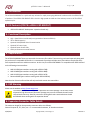
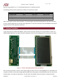
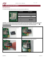
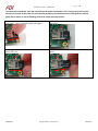
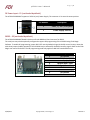
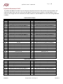
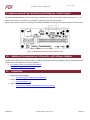
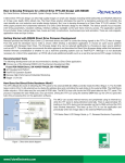
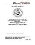
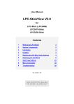
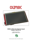
1
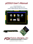
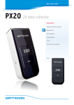
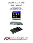
µEZGUI-EXP-BRKOUT User’s Manual Covers the following products: µEZGUI-EXP-BRKOUT Copyright ©2014, Future Designs, Inc., All Rights Reserved µEZGUI User’s Manual P a g e |2 Table of Contents 1. 2. 3. 4. 5. 6. 7. 8. Introduction __________________________________________________________________________ Kit Contents (FDI PN: uEZGUI-EXP-BRKOUT) _________________________________________________ Functional Description __________________________________________________________________ Requirements ________________________________________________________________________ ESD Warning _________________________________________________________________________ Expansion Connector Cable Details ________________________________________________________ Startup Procedure _____________________________________________________________________ I/O Connector Descriptions ______________________________________________________________ MicroSD Socket J5 _____________________________________________________________________ DC Power Input – P1 (not loaded by default) ________________________________________________ RS232 – P2 (not loaded by default) ________________________________________________________ Expansion Connectors J1 & J2 ____________________________________________________________ 9. Expansion Board Top Level Mechanical Diagram / Board Layout _________________________________ 10. Additional Documentation, Schematics, and Software Updates _________________________________ 11. Useful links___________________________________________________________________________ 3 3 3 3 3 3 4 5 5 7 7 8 9 9 9 Important Legal Information Information in this document is provided solely to enable the use of Future Designs products. FDI assumes no liability whatsoever, including infringement of any patent or copyright. FDI reserves the right to make changes to these specifications at any time, without notice. No part of this document may be reproduced or transmitted in any form or by any means, electronic or mechanical, for any purpose, without the express written permission of Future Designs, Inc. 996 A Cleaner Way, Huntsville, AL 35805. For more information on FDI or our products please visit www.teamfdi.com. NOTE: The inclusion of vendor software products in this kit does not imply an endorsement of the product by Future Designs, Inc. 2014 Future Designs, Inc. All rights reserved. uEZ® is a registered trademark of Future Designs, Inc. Microsoft, MS-DOS, Windows, Windows XP, Microsoft Word are registered trademarks of Microsoft Corporation. Other brand names are trademarks or registered trademarks of their respective owners. FDI PN: MA00039 Revision: 1.0, 4/28/2014 Printed in the United States of America 4/30/2014 Copyright ©2014, Future Designs, Inc Revision 1 µEZGUI User’s Manual P a g e |3 1. Introduction The uEZGUI-EXP-BRKOUT is a quick and easy solution for rapid prototyping additional hardware with the uEZGUI family of products. The uEZGUI-EXP-BRKOUT offers a built-in high-speed microSD card slot and easy access to all 70 uEZGUI expansion pins. 2. Kit Contents (FDI PN: uEZGUI-EXP-BRKOUT) uEZGUI-EXP-BRKOUT development expansion board only 3. Functional Description High –Speed 4 bit microSD card(not supported on Renesas uEZGUIs) 70 Pin GPIO Expansion Optional RS232/RS485 Serial Communication Optional 5V Power Input Optional Power Status LEDs Ability to disconnect unused features 4. Requirements The uEZGUI-EXP-BRKOUT does not come with the necessary flex cables. These must be purchased separately along with the purchase of a compatible uEZGUI kit. It is recommend to purchase multiple sets of flex cables as they break easily from repeated connections and disconnections. At this time, the uEZGUI-EXP-BRKOUT is compatible with uEZGUIs based on the following microcontrollers: NXP LPC1788 (part numbers starting with uEZGUI-1788) NXP LPC4088 (part numbers starting with uEZGUI-4088) NXP LPC2478 (part numbers starting with uEZGUI-2478) Renesas RX62N (part numbers starting with uEZGUI-RX62N) Note that the 4-bit microSD card slot will only work with certain microcontrollers. 5. ESD Warning Please see the website at http://www.uezgui.com The uEZGUI-EXP-BRKOUT is shipped in a protective anti-static package. The kit must not be subjected to high electrostatic potentials. Damage may occur to the boards that will not be covered under warranty. General practice for working with static sensitive devices should be followed when working with the expansion board. 6. Expansion Connector Cable Details The maximum length for the expansion connector cables is as follows: General Purpose IO, TTL, Serial, etc = 6” recommended maximum, 8” absolute maximum 4/30/2014 Copyright ©2014, Future Designs, Inc Revision 1 P a g e |4 µEZGUI User’s Manual Ethernet, high-speed IO, etc = 3” recommended maximum, 4” absolute maximum The following table provides example part numbers for the expansion cables: Description 3” 20-pin 0.5mm 6” 20-pin 0.5mm 3” 50-pin 0.5mm 6” 50-pin 0.5mm Mfg Molex Molex Molex Molex Mfg PN 21020-0209 21020-0215 21020-7650 21020-0548 Digi-Key Pn WM10226-ND WM10218-ND WM10231-ND WM10223-ND Note: These lengths are only recommendations. The actual lengths utilized will be dependent on the expansion board circuitry, layouts and general environment of the application. It is up to the customer to test and validate the functional operation and use of the expansion connectors. 7. Startup Procedure To get started with the uEZGUI-EXP-BRKOUT, please connect the 50 pin and 20 pin FFCs to the uEZGUI as shown. The uEZGUI-RX62N-35QT does not support the 20 pin expansion. Take care not to damage the FFCs as they are very fragile. Figure 1 – uEZGUI-1788-43WQR with uEZGUI-EXP-BRKOUT After connecting the cables, connect a 5V DC power supply (1A min) to the P1 on the EXP-BRKOUT or to the uEZGUI unit to power on the unit. At this time the high speed microSD card is only support on LPC1788 uEZGUI units. The out-of-thebox demo does not include the video player. This will need to be enabled inside of the project’s Config_Build.h file. 4/30/2014 Copyright ©2014, Future Designs, Inc Revision 1 P a g e |5 µEZGUI User’s Manual 8. I/O Connector Descriptions MicroSD Socket J5 The UEZGUI-EXP-BRKOUT Board includes one 4 bit high speed microSDHC card. Pin Number 1 2 3 4 5 6 7 8 Description MCI DAT 2 MCI DAT 3 MCI CMD 3.3V MCI Clock Ground MCI DAT 0 MCI DAT 1 WARNING: The microSD card must only be removed using the spring loaded “push-pull” mechanism on the microSD socket. Improper forceful removal of the microSD card will result in permanent damage to the socket that is not covered under warranty. To insert the card, just push it into the socket until a “click” sound is heard. Start with the microSD card in this position relative to the microSD slot with the text and “lip” facing up. Next gently insert the card partially into the socket. Use your figure to gently push the card into the socket until it clicks. At this point the microSD card is fully inserted. It should not fall out, even if the unit is shaken vigorously. 4/30/2014 Copyright ©2014, Future Designs, Inc Revision 1 µEZGUI User’s Manual P a g e |6 To remove the microSD card, press the card back into the socket until another “click” sound is heard, then release pressure on the card. At this point, the card should be partially ejected from the socket. Finally grab the card and gently pull to remove it. See the following pictures for proper micro-SD removal: To remove the microSD card, gently push it into the socket again until it “clicks”, and then release your figure. At this point, the microSD card should partially stick out of the socket. Carefully grab the edges or sides of the microSD card and gently pull it out. At this point the microSD card is fully removed from the socket. 4/30/2014 Copyright ©2014, Future Designs, Inc Revision 1 P a g e |7 µEZGUI User’s Manual DC Power Input – P1 (not loaded by default) The uEZGUI-EXP-BRKOUT supports a 5VDC 1A (min) Power Supply. The connector is 2.1mm with center positive. Pin Number Description 1 5VDC, +/- 10%, 1.0A (min) 2 Power Supply Ground RS232 – P2 (not loaded by default) The uEZGUI-EXP-BRKOUT Board includes one female DB9 Serial Port Connector for RS232. The serial port may also be optionally configured to support ISP programming of the LPCXXXX using Flash Magic Software. To enable ISP programming, jumper JP6 & JP7 must be loaded, along with the ISP control circuitry. Note that with these jumpers loaded, operation of the LPCXXXX may be affected by the RS232 interface signals. Refer to the Flash Magic user manual for details. The ISP programming mode only applies to NXP LPC based uEZGUI units. Pin Number 1 2 3 4 5 6 7 8 9 4/30/2014 Copyright ©2014, Future Designs, Inc Description No Connect TXD (Output) RXD (Input) Optional RESET input Signal Ground No Connect Optional ISP Entry No Connect No Connect Revision 1 µEZGUI User’s Manual P a g e |8 Expansion Connectors J1 & J2 The uEZGUI-EXP-BRKOUT includes 50 pin and 20 pin FFC Expansion Connectors that connect to the host uEZGUI. The table below details which pins are used on the EXP-BRKOUT and what they are used for on the EXP-BRKOUT. All of these pins are brought out to the standard 1/8” header breakout on the EXP-BRKOUT for ease of connecting additional hardware. Pin 1 3 5 7 9 11 13 15 17 19 21 23 25 27 29 31 33 35 37 39 41 43 45 47 49 1 3 5 7 9 11 13 15 17 19 4/30/2014 J1/J3 Connectors 50 pin Function used on EXP-BRKOUT Pin Function used on EXP-BRKOUT Ground 2 Expansion pin not used by EXP-BRKOUT Expansion pin not used by EXP-BRKOUT 4 High Speed microSD card CMD High Speed microSD card CLK 6 Expansion pin not used by EXP-BRKOUT Expansion pin not used by EXP-BRKOUT 8 Expansion pin not used by EXP-BRKOUT Expansion pin not used by EXP-BRKOUT 10 Ground Expansion pin not used by EXP-BRKOUT 12 Expansion pin not used by EXP-BRKOUT Expansion pin not used by EXP-BRKOUT 14 Expansion pin not used by EXP-BRKOUT Expansion pin not used by EXP-BRKOUT 16 Expansion pin not used by EXP-BRKOUT Expansion pin not used by EXP-BRKOUT 18 Expansion pin not used by EXP-BRKOUT Expansion pin not used by EXP-BRKOUT 20 Expansion pin not used by EXP-BRKOUT Expansion pin not used by EXP-BRKOUT 22 Ground Reset switch/ISP reset input into host uEZGUI 24 Reset output from µC on uEZGUI Expansion pin not used by EXP-BRKOUT 26 Expansion pin not used by EXP-BRKOUT Expansion pin not used by EXP-BRKOUT 28 Expansion pin not used by EXP-BRKOUT Ground 30 Expansion pin not used by EXP-BRKOUT Expansion pin not used by EXP-BRKOUT 32 3.3V power from uEZGUI host unit’s PSU Expansion pin not used by EXP-BRKOUT 34 Expansion pin not used by EXP-BRKOUT Expansion pin not used by EXP-BRKOUT 36 Expansion pin not used by EXP-BRKOUT Expansion pin not used by EXP-BRKOUT 38 Expansion pin not used by EXP-BRKOUT Ground 40 Used for optional ISP Entry to NXP uEZGUIs RS232 Port RX 42 RS232 Port TX USB Host/Device DP 44 USB Host/Device DM USB Host/Device VBUS 5V 46 5V power supply to host uEZGUI unit 5V power supply to host uEZGUI unit 48 5V power supply to host uEZGUI unit 3.3V power from uEZGUI host unit’s PSU 50 3.3V power from uEZGUI host unit’s PSU J2/J4 Connectors 20 pin Ground 2 Expansion pin not used by EXP-BRKOUT Expansion pin not used by EXP-BRKOUT 4 Expansion pin not used by EXP-BRKOUT High Speed SD card DAT3 6 High Speed SD card DAT2 High Speed SD card DAT1 8 High Speed SD card DAT0 Expansion pin not used by EXP-BRKOUT 10 Expansion pin not used by EXP-BRKOUT Expansion pin not used by EXP-BRKOUT 12 Expansion pin not used by EXP-BRKOUT 5V power supply to host uEZGUI unit 14 Ground Expansion pin not used by EXP-BRKOUT 16 Expansion pin not used by EXP-BRKOUT Expansion pin not used by EXP-BRKOUT 18 Expansion pin not used by EXP-BRKOUT Expansion pin not used by EXP-BRKOUT 20 Ground Copyright ©2014, Future Designs, Inc Revision 1 µEZGUI User’s Manual P a g e |9 9. Expansion Board Top Level Mechanical Diagram / Board Layout The uEZGUI-EXP-BRKOUT has 4 screw mounts that accept #6 size screws. The total board dimensions are 4.5” x 1.75”. Each of the 4 corner screw mounts is centered 0.2” away from each side of the board. Below is the top level mechanical drawing of the uEZGUI-EXP-BRKOUT showing all of the part positions and silk screen: Figure 2 –Mechanical Dimensions (Component View) 10. Additional Documentation, Schematics, and Software Updates Complete Users Manuals, Schematics, Software updates, and documentation are available from the following websites (please refer to the websites for the latest updates): http://www.uEZGUI.com/uEZGUI-EXP-BRKOUT http://sourceforge.net/projects/uez/ 11. Useful links Segger Mini-JTAG Debugger o http://www.segger.com/cms/jlink-software.html Rowley Crossworks IDE download for 30-day evaluation o http://www.rowley.co.uk uEZ software quick start guide o http://www.teamfdi.com/development-tools-kits/uez.php 4/30/2014 Copyright ©2014, Future Designs, Inc Revision 1