1
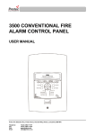
3300 NON-ADDRESSABLE
FIRE ALARM CONTROL PANEL
USER MANUAL
Protec Fire Detection PLC, Protec House, Churchill Way, Nelson, Lancashire, BB9 6RT.
Telephone:
Fax:
Web:
Email:
+44 (0) 1282 717171
+44 (0) 1282 717273
www.protec.co.uk
[email protected]
Document Revision Details
Issue
0
Modification Detail
Document Creation
93-531-79 Issue 0
Author
NH
Page 2 of 24
Date
12/02/07
© Protec Fire Detection PLC 2007
Table of Contents
1.0
INTRODUCTION ...........................................................................................................................5
2.0
USER RESPONSIBILITIES ..........................................................................................................6
2.1
3.0
ROUTINE TESTING OF THE SYSTEM ........................................................................................7
3.1
3.2
3.3
3.4
3.5
3.6
4.0
Testing the Indications (Lamp Test) .....................................................................................11
SYSTEM FIRE INDICATIONS ....................................................................................................11
6.1
6.2
6.3
6.4
7.0
Access Level 1 (General User) ..............................................................................................9
Access Level 2 (Authorised User) ..........................................................................................9
INDICATIONS AND CONTROLS ...............................................................................................10
5.1
6.0
Daily Inspection ......................................................................................................................7
Weekly Test ............................................................................................................................7
Monthly Test ...........................................................................................................................7
Quarterly Test .........................................................................................................................7
Annual Test ............................................................................................................................8
5 Yearly Test ..........................................................................................................................8
ACCESS LEVELS – AN EXPLANATION.....................................................................................9
4.1
4.2
5.0
Requirements of the Appointed Responsible Person ............................................................6
‘General Fire’ Indicator Illuminated.......................................................................................11
‘MCP Fire’ Indicator Illuminated ...........................................................................................11
Fire Zones 1 to 8 Flashing ....................................................................................................11
Fire Zones 1 to 8 Illuminated Steady ...................................................................................11
SYSTEM FAULT INDICATIONS .................................................................................................12
7.1
7.2
7.3
7.4
7.5
7.6
7.7
Zone Faults ...........................................................................................................................12
System Faults .......................................................................................................................12
Alarm Faults .........................................................................................................................12
Power Supply Faults ............................................................................................................12
Fire Link Fault .......................................................................................................................12
Aux 24V Fault .......................................................................................................................12
Repeat Panel Fault ...............................................................................................................12
8.0
SYSTEM DELAYS ......................................................................................................................13
9.0
COINCIDENCE ZONES ..............................................................................................................13
10.0
RESPONSE TO AN ALARM ......................................................................................................14
10.1
10.2
10.3
10.4
10.5
10.6
10.7
11.0
Automatic Detection .............................................................................................................14
Manual Detection .................................................................................................................14
Delayed Activation ................................................................................................................14
Silencing the Alarms .............................................................................................................14
Resetting The 3300 After An Alarm......................................................................................14
New Zone Into Alarm ............................................................................................................14
Activating The Alarms Manually ...........................................................................................14
SYSTEM DISABLEMENTS ........................................................................................................15
11.1
11.2
11.3
11.4
Zone Disablements ..............................................................................................................15
Alarm Disablements .............................................................................................................15
Delay Disablement ...............................................................................................................15
Fire Link Disablement ...........................................................................................................15
93-531-79 Issue 0
Page 3 of 24
© Protec Fire Detection PLC 2007
12.0 PROGRAMMING SYSTEM DISABLEMENTS ..............................................................................16
12.1
12.2
12.3
12.4
13.0
To Disable Zones .................................................................................................................16
To Disable Alarm Outputs ....................................................................................................17
To Disable Delays ................................................................................................................17
To Disable the Fire Link .......................................................................................................18
TESTING DETECTION ZONES ..................................................................................................19
13.1
Programming a Zone into Test Mode ...................................................................................19
14.0
APPENDIX 1 3300 SYSTEM SETUP RECORD ........................................................................20
15.0
APPENDIX 2 3300 EVENT LOG ...............................................................................................21
16.0
APPENDIX 3 3300 OPERATION QUICK REFERENCE GUIDE ...............................................23
16.1
16.2
16.3
16.4
16.5
16.6
16.7
Muting the Internal Buzzer ...................................................................................................23
Entering Access Level 2 .......................................................................................................23
Returning to Access Level 1.................................................................................................23
Silencing the Alarms .............................................................................................................23
Sounding the Alarms ............................................................................................................23
Resetting the Panel ..............................................................................................................23
Testing the Indicators and Internal Buzzer ...........................................................................23
93-531-79 Issue 0
Page 4 of 24
© Protec Fire Detection PLC 2007
1.0
Introduction
The Protec 3300 Fire Alarm Control Panel has been designed and manufactured in the United
Kingdom and complies fully with current standards dictating fire alarm system design practice (EN54
parts 2 and 4).
As the integrity and reliability of a fire alarm system is vital the 3300 monitors all critical paths for
faults. The detector and sounder wiring is constantly monitored to check it is correct and is not faulty.
The internal power supply regularly performs self checks to ensure it is in full working order and that
the stand-by batteries are in a good state.
Any faults detected are reported on the front panel display of the 3300, a fault output is also provided
to be connected to external systems (a remote monitoring centre, for example) to signal that the 3300
has a fault and attention is required.
The 3300 is also capable of distinguishing between automatic (detector) and manual (manual call
point) zone activation. Given this extra information the panel can make decisions on the type of zone
activation and take appropriate action, for example a zone delay will be immediately overridden by a
manual activation.
This manual includes a 3300 system set up sheet and a 3300 event log as appendices at the rear of
the manual.
The system set up sheet must be completed by the commissioning engineer prior to handing the
system over to the customer. The system set up sheet details exactly how the system has been set
up and programmed by the commissioning engineer and, being the only such record, should be kept
in a safe place.
The 3300 event log must be completed by the authorised user of the system each time a 3300 event
(fire or fault) occurs. It is advisable to make copies of the blank event log to allow the log to be
continued when the sheet included has been filled up.
Important Note:
There are no user serviceable parts inside the 3300 panel. Any internal maintenance work
MUST be carried out by a competent person trained to undertake such work. A separate
installation, commissioning and maintenance manual is available.
This product has been manufactured in conformance with the requirements of all applicable EU
council directives.
93-531-79 Issue 0
Page 5 of 24
© Protec Fire Detection PLC 2007
2.0
User Responsibilities
The registered owner of the fire alarm system has specific responsibilities regarding the installation,
testing and maintenance of the fire alarm system.
BS5839 Pt 1: 2002 states that the owner of the fire alarm system must appoint a single, named person
to supervise all matters regarding the fire alarm system.
Below is a brief summary of the responsibilities expected of the appointed person.
Important Note:
It is advised that a full copy of BS5839 Pt 1: 2002 is obtained and thoroughly read and
understood.
2.1
Requirements of the Appointed Responsible Person
•
Ensure the that the fire alarm equipment is checked at least once every 24 hours to ensure there
are no faults on the system. Report any faults to the site maintenance manager.
•
Ensure that arrangements are in place for correct testing of the fire alarm system (as specified in
BS5839 Pt 1 : 2002 Section 6. Summarised in section 3.0 of this document.
•
Ensure that the system event log is kept up to date and is available for inspection by
any authorised person when required. An example log book is included in appendix 15.0 of this
document.
•
Ensure that all occupants of the protected premises are trained how to use the system properly
and that they are aware of what action to take in the event of an alarm.
•
Ensure that false alarms are minimised.
•
Ensure all detectors and manual call points remain un-obstructed. Detectors must have at least
500mm clear space preserved in all directions around them.
•
Ensure that six spare manual call point frangible elements (glass fronts) and appropriate fitting
tools are available as replacements for use in the event a manual call point is activated.
93-531-79 Issue 0
Page 6 of 24
© Protec Fire Detection PLC 2007
3.0
Routine Testing of the System
Recommendations for testing of the system are detailed in BS5839 Pt 1: 2002 (Section 6)
The routine testing is briefly detailed below.
3.1
Daily Inspection
•
Check that the ‘Supply Present’ indicator is illuminated.
•
Check for any faults on the system and report these to the site maintenance manager.
3.2
Weekly Test
Note: During the test you may wish to temporarily place the zone to be tested into test mode.
•
Perform an indicator test (Lamp Test) to check the integrity of the front panel indications, and
internal buzzer.
•
Ensure no manual call points or detectors are obstructed.
•
Operate a manual call point or detector during normal working hours to ensure the fire alarm
system operates correctly.
•
A different manual call point or detector on a different zone should be tested each week, in this
way all the devices on all the zones are tested.
•
Ensure the system sounders are operational.
•
Ensure the sounders are not operated for longer than 1 minute during testing. Genuine alarms can
then be distinguished by the occupants of the building.
3.3
Monthly Test
•
Perform the weekly test recommended in 3.2 and..
•
If an automatic generator is used as part of the mains failure back-up system it should be started
up once each month by simulated failure of the normal power supply, and then run in this mode for
at least 1 hour.
•
Visually inspect the stand-by batteries and their connections. Check that the batteries are capable
of supplying the alarm sounders.
3.4
Quarterly Test
•
Perform the monthly test recommended in 3.3 and..
•
Ensure the system event log is up to date and all entries are correct. Check that any faults noted
have been rectified.
93-531-79 Issue 0
Page 7 of 24
© Protec Fire Detection PLC 2007
3.5
•
•
3.6
•
Annual Test
Perform the quarterly test recommended in 3.4 and..
Test every detector, manual call point and all auxiliary equipment for correct functionality.
5 Yearly Test
Carry out a full wiring check in accordance with the testing and inspection requirements of the
relevant National wiring regulations (I.E.E regulations for the UK).
93-531-79 Issue 0
Page 8 of 24
© Protec Fire Detection PLC 2007
4.0
Access Levels – An Explanation
The 3300 has two access levels to allow users of different authorisation levels access to various parts
of the system. The access levels and a description of functions available are given in the next
sections.
4.1
Access Level 1 (General User)
Access level 1 allows the general user to view the status of the 3300 at any time. Zone fire and fault
states are clearly displayed as are any current system faults and disablements.
Full detail of the front panel display is given in the next section.
The following functions may be performed at access level 1.
•
•
•
4.2
Muting the 3300 internal buzzer.
Accepting current fire and fault conditions
Entering access level 2.
Access Level 2 (Authorised User)
Access level 2 allows the authorised user access to various critical system functions. To enter access
level 2 from access level 1 enter the user code 1 3 4 4 2 on code entry models, or turn the key on keyswitch models
When the correct code has been entered, or the key-switch has been turned the
‘Level 2 Accessed’ indicator will light showing that level 2 functions are available.
To return back to access level 1, press button 4, or return the key-switch back to its normal position.
Note: As a security measure on code entry models the 3300 will return back to access level 1 if no
key activity has been detected for 2 minutes.
The following functions may be accessed at access level 2.
•
•
•
•
•
•
•
•
•
Silencing an alarm condition.
Sounding the alarms.
Resetting the panel after an alarm activation.
Testing the front panel indications, and internal buzzer.
Programming a zone into test mode (only one test zone at once is permitted).
Disablement of detector circuits.
Disablement of alarm circuits.
Disablement of any programmed delays (detector and fire link).
Disablement of the fire link interface (if fitted).
93-531-79 Issue 0
Page 9 of 24
© Protec Fire Detection PLC 2007
5.0
Indications and Controls
The 3300 has a comprehensive front panel display enabling the state of the 3300 to be rapidly
determined by inspection of the indications.
•
Zone fires are displayed on row 1 of the display.
•
Zone faults (indicator flashing), Zonal disablements (indicator steady + ‘General Disablement’
indicator) and zones in test mode (indicator steady + ‘General Test’ indicator) are shown on row 2
of the display.
•
System disablements are shown on the right hand side of row 3 of the display.
•
System faults are displayed on row 4 of the display.
Figure 5.0 illustrates the front panel indications.
Figure 5.0 3300 Front panel Indications and controls
Zone Fire indications
Zone Fault / Disablement / test
Indications
System control
push buttons
Fault Indications
Push buttons used for
code entry, lamp test
and programming
93-531-79 Issue 0
Page 10 of 24
System
disablement
indications
© Protec Fire Detection PLC 2007
5.1
Testing the Indications (Lamp Test)
To test the functionality of the front panel indicators.
1.
At access level 1 enter the 5 digit user code 1 3 4 4 2 or turn the keyswitch (depending
on the model purchased). The ‘Level 2 accessed’ indicator will light.
2.
Press button ‘1’. The 3300 will light each row on the display in turn and sound the
internal buzzer.
3.
Confirm that each indicator is operational, and that the buzzer can be heard clearly.
If a problem exists inform the site maintenance manager immediately.
4.
Return to access level 1 by pressing button 4.
6.0
System Fire Indications
The 3300 displays fire information on row 1 of the front panel display. The following sections detail
what each indicator means.
6.1
‘General Fire’ Indicator Illuminated
The 3300 has detected a fire on one of its zones, or has been activated from another piece of
equipment connected to its ‘remote alarm’ input.
The building fire plan should be executed immediately.
6.2
‘MCP Fire’ Indicator Illuminated
A manual call point has been activated on one of the detection zones.
6.3
Fire Zones 1 to 8 Flashing
The 3300 has detected a fire on the relevant zone. This will always be accompanied by the
‘General Fire’ indicator.
6.4
Fire Zones 1 to 8 Illuminated Steady
The 3300 has detected a fire on the relevant zone. The fire has been accepted by a user
pressing the ‘Mute Buzzer’ button.
93-531-79 Issue 0
Page 11 of 24
© Protec Fire Detection PLC 2007
7.0
System Fault Indications
When the 3300 has detected a fault in the critical operating path of the system it will display this on the
front panel display. The internal buzzer will also sound intermittently (slowly).
The ‘General Fault’ indicator will be illuminated and is always accompanied by other indicator(s)
detailing the fault.
In general, fault indicators flash until the fault is accepted (by pressing the ‘Mute Buzzer’ button) the
fault indicator then lights steady and the internal buzzer will be muted. Further faults activate the
buzzer again.
In the event of any fault the following action should be taken:
•
•
Mute the fault by pressing the ‘Mute Buzzer’ button on the panel.
Note the fault down in the Log Book and take action to remedy the fault. In all cases expert
advice should be sought.
When the fault has been rectified the fault indicator will automatically extinguish.
The following sections give descriptions of each possible fault.
7.1
Zone Faults
The 3300 shows any faults on the detection zones on row 2 of the front panel display. The ‘General
Fault’ indicator will be illuminated accompanied by the relevant zone indicator. Pressing ‘Mute Buzzer’
will mute the buzzer but WILL NOT make the zone indicator go steady.
7.2
System Faults
The 3300 performs many self tests to ensure the software is working correctly.
The fault should be cleared by pressing ‘Silence Alarms’ then ‘Reset Panel’ whilst in access level 2.
If the fault re-occurs with 3 minutes the 3300 has a microprocessor fault, and the maintenance
manager must be alerted.
7.3
Alarm Faults
A fault has been detected on one or more of the four sounder outputs. One or more of the sounder
circuits may no longer operate correctly.
7.4
Power Supply Faults
A fault has been detected in the power supply module of the 3300. This may be because the local
mains supply has failed or because the internal stand-by batteries or charger are faulty.
7.5
Fire Link Fault
A fault has been detected on the monitored fire link path. This may be a wiring fault of the fire link
interface fault. The connection to the fire station link is no longer reliable. Expert advice should be
obtained immediately.
7.6
Aux 24V Fault
A fault has been detected with the Auxiliary 24V supply output of the panel.
7.7
Repeat Panel Fault
A fault has been detected on a 3300 repeat panel connected to the 3300 main panel, or the wiring to
the repeat panel is faulty.
93-531-79 Issue 0
Page 12 of 24
© Protec Fire Detection PLC 2007
8.0
System Delays
Delays may have been programmed in the 3300 to allow a predetermined time from a zone activation
until:
•
•
The alarm outputs and global fire contacts activate.
The fire link activates.
This can be useful to allow time for the cause of the activation to be investigated by a responsible
person. If the cause of the activation is found to be legitimate the alarm outputs can be manually
activated. If the cause of the activation is found to be a false alarm the 3300 can be reset.
A delay time can be programmed into one, or more zones. The delay time set up on the 3300 applies
to all zones and can be set to a maximum 10 minutes.
The fire link delay time is independent of the zone delay time and can be set up to a maximum of 10
minutes locally on the fire link interface.
The presence of a programmed delay is indicated by the ‘Output Delay’ indicator being illuminated.
The 3300 system set-up chart must be consulted to determine exactly which zones have been
delayed and what the delay time is set to.
If the ‘Silence Alarms’ button is pressed while a delay is running, the alarm outputs will not be
activated when the delay expires. The global fire contacts, however, will still be activated.
Note: Zone delays only pertain to automatic zone activations. A manual activation on a zone will
always override a programmed zone delay.
9.0
Coincidence Zones
At the time of commissioning, one or more zones may have been programmed as ‘coincidence’ zones.
This means that two, or more, of the coincidence zones must activate together before the 3300 will
sound the alarms or activate the Global Fire Contacts.
If one coincidence zone is triggered the cause of the activation must be investigated, if no action is
taken within 2 minutes the 3300 will sound the alarms and activate the Global Fire contacts.
If the cause of the alarm is deemed to be false the 3300 should be reset.
The only way to determine if coincidence zones have been programmed into the system is by
consulting the system set-up chart (appendix 1 of this document).
Note:
•
•
A single activated coincidence zone will time out and sound the alarms after 2 minutes.
A zone programmed as coincidence will be overridden by a manual call point activation on that
zone.
93-531-79 Issue 0
Page 13 of 24
© Protec Fire Detection PLC 2007
10.0 Response to an Alarm
10.1
Automatic Detection
If a smoke detector or heat detector operates on a zone of the 3300 this is known as an automatic
operation. The 3300 responds by.
•
•
•
•
•
•
10.2
Illuminating the ‘General Fire’ indicator.
Flashing the relevant zone fire indicator.
Fast intermittent sounding of the internal buzzer.
Activating non-disabled alarm outputs (after a delay expiry, if programmed).
Activating the Global Fire contacts.
Activating the Fire Link output (if fitted and not disabled).
Manual Detection
If a Manual Call Point is operated on the zone of a 3300 this is known as manual operation. The 3300
responds by.
•
•
•
•
•
•
•
•
•
10.3
Illuminating the ‘General Fire’ indicator.
Illuminating the ‘MCP Fire’ indicator.
Flashing the relevant zone fire indicator.
Fast intermittent sounding of the internal buzzer.
Activating non-disabled alarm outputs (immediately).
Activating the Global Fire contacts.
Activating the Fire Link output (if fitted and not disabled).
Overriding any zone delays that may be programmed.
Re-sounding the alarms if the zone had previously experienced a silenced
automatic activation.
Delayed Activation
Please see section 8.0
10.4
Silencing the Alarms
The alarms and internal buzzer may be silenced by pressing ‘Silence Alarms’ when in access level 2.
10.5
Resetting The 3300 After An Alarm
After the cause of the alarm has been determined (and entered in the log by the authorised user) the
3300 may be reset if required. When in access level 2 press ‘Silence Alarms’ then press ‘Reset Panel’.
The 3300 will reset any latched detectors on its zone connections. Manual call points must be reset
manually at the local location.
10.6
New Zone Into Alarm
If a new zone goes into alarm or a previously silenced zone (triggered by an automatic device) has a
manual activation, the 3300 will re–activate the alarms and re-sound the internal buzzer.
10.7
Activating The Alarms Manually
To evacuate the building press ‘ Sound Alarms’ when in access level 2. The alarm outputs will be
activated but the Global Fire Contacts and the Fire Link Interface WILL NOT be activated.
93-531-79 Issue 0
Page 14 of 24
© Protec Fire Detection PLC 2007
11.0 System Disablements
Various disablements may be programmed into the 3300 by the authorised user.
In some situations it may be advantageous to ‘turn off’ certain functions to suit specific site conditions.
The 3300 permits the following disablements to be made by the authorised user, at access level 2.
11.1
Zone Disablements
Fires and faults from the disabled zone are inhibited.
11.2
Alarm Disablements
Activations and faults from the disabled alarm circuit are inhibited.
11.3
Delay Disablement
Any programmed zone or fire link delays are overridden.
Important Note:
Delays will have been programmed into the 3300 for valid reasons. Please refer to the section
on delays and consult the system set-up record (appendix 1) before making adjustments to
this part of the system.
11.4
Fire Link Disablement
Activations and faults on the fire link output are inhibited.
Important Note:
Please refer to the section on the fire link and consult the system set-up record (appendix 1)
before making adjustments to this critical part of the system.
93-531-79 Issue 0
Page 15 of 24
© Protec Fire Detection PLC 2007
12.0 Programming System Disablements
It is possible for the authorised user at access level 2 to program zone, alarm, delay and fire link
disablements.
12.1
To Disable Zones
The 3300 can have one, or more, of its detector zones disabled. When a zone is disabled faults and
activations from that zone are inhibited.
1. From access level 1 enter your 5 digit user code 1 3 4 4 2 or turn the key-switch (depending on
the model purchased). The ‘Level 2 Accessed’ indicator will illuminate.
2. Press button 2 once – The ‘General Disablement’ indicator will illuminate steady to show the zone
disablement option is selected (the normal front panel display is temporarily replaced with the
programming display). Any current disablements will be displayed on row 1 of the display. Accept
the option by pressing button 3.
3. The ‘General Disablement’ indicator will flash, showing this option has been accepted.
4. Highlight the zone to be disabled by pressing button 2 until the required zone is reached.
5. Press button 1 to show that the zone is to be disabled / not disabled. If disabled the relevant row 1
indicator will be illuminated.
6. Follow the procedure above until all zones that are to be disabled have their row 1 indicators
illuminated.
7.
Press button 3 to return to the selection menu.
8. Press button 4 to accept and program the disablement set-up and return to access level 2
9. The yellow ‘General Disablement’ indicator will be illuminated steady, as will the row 2
disablement indicator for the relevant zone(s).
93-531-79 Issue 0
Page 16 of 24
© Protec Fire Detection PLC 2007
12.2
To Disable Alarm Outputs
The 3300 can have alarm circuits 1 and 2 and/or alarm circuits 3 and 4 disabled. When an alarm
circuit is disabled faults and activations on that circuit are inhibited.
1. From access level 1 enter your 5 digit user code 1 3 4 4 2 or turn the key-switch (depending on
the model purchased). The ‘Level 2 Accessed’ indicator will illuminate.
2. Using button 2 scroll to the ‘Alarm Outputs’ indication. Any current alarm disablements will be
displayed on row 1 of the display, on zones 1 and 2. Accept this option by pressing button 3.
3. The ‘Alarm Outputs’ indicator will flash, showing this option has been accepted.
4.
Highlight the alarm circuit pair to be disabled by pressing button 2
•
Highlight zone 1 indicator on row 2 if alarm circuits 1 and 2 are to be disabled.
•
Highlight zone 2 indicator on row 2 if alarm circuits 3 and 4 are to be disabled.
5. Press button 1 to show that it is to be disabled / not disabled. The relevant row 1 indicator will be
illuminated if the alarm circuit is disabled.
6.
Press button 3 to return to the selection menu.
7. Press button 4 to accept and program the disablement set-up and return to access level 2.
8. The yellow ‘General Disablement’ indicator will be illuminated steady, as will the yellow ‘Alarm
Outputs’ indicator.
12.3
To Disable Delays
It is possible for the authorised user to override any delays (zonal or fire link) that may have been set
up when the system was commissioned. The procedure to do this is as follows.
1. From access level 1 enter your 5 digit user code 1 3 4 4 2 or turn the key-switch (depending on
the model purchased). The ‘Level 2 Accessed’ indicator will illuminate.
2. Using button 2 scroll to the ‘Alarm Outputs’ indication. Any current setting in this option will be
displayed on row 1 of the display, on zone 3. Accept this option by pressing button 3.
3. The ‘Alarm Outputs’ indicator will flash, showing this option has been accepted.
4. Select the delay override option by pressing button 2 until the row 2 indicator for zone 3 is
illuminated.
5. Press button 1 to show that delays are to be overridden / not overridden. If delays are overridden
the zone 3 indicator on row 1 will be illuminated.
6.
Press button 3 to return to the selection menu.
7.
Press button 4 to accept and program the set-up and return to access level 2.
8. The ‘Output Delay’ indicator will be extinguished. All delays (zonal and fire link) are
now overridden.
93-531-79 Issue 0
Page 17 of 24
© Protec Fire Detection PLC 2007
12.4
To Disable the Fire Link
It is possible for the authorised user (at access Level 2) to disable the Fire Link interface (if fitted).
Disabling the interface inhibits Fire Link faults and activations.
1. From access level 1 enter your 5 digit user code 1 3 4 4 2 or turn the key-switch (depending on
the model purchased). The ‘Level 2 Accessed’ indicator will illuminate.
2. Using button 2 scroll to the ‘Alarm Outputs’ indication. If the fire link is disabled the zone 4
indicator on row 1 will be illuminated. Accept this option by pressing button 3.
3. The ‘Alarm Outputs’ indicator will flash, showing this option has been accepted, and any current
settings in this option will be displayed on row 1 of the display, on zone 4.
4. Select the ‘Disable Fire Link’ option by pressing button 2 until the indicator for zone 4 is
illuminated.
5. Press button 1 to show that the fire link is to be disabled / not disabled.
6.
Press button 3 to return to the selection menu.
7.
Press button 4 to accept and program the set-up and return to access level 2.
8.
The ‘Fire Link’ and ‘General Disablement’ indicators will be Illuminated.
93-531-79 Issue 0
Page 18 of 24
© Protec Fire Detection PLC 2007
13.0 Testing Detection Zones
To aid the required fire alarm test schedule to be performed, the 3300 allows one zone at a time to be
put into ‘test mode’. In this mode, upon an alarm on the test zone, the 3300 activates the alarm
outputs for 4 seconds then resets. This allows a zone of detectors to be easily tested without having to
reset the panel manually after each activation.
Note:
When a zone is in test mode the Global Fire Contacts and Fire Link (if fitted) are not activated when
the test zone goes into alarm.
Alarms on non-test zones will prevent the 3300 resetting automatically.
13.1
Programming a Zone into Test Mode
1. From access level 1 enter your 5 digit user code 1 3 4 4 2 or turn the key-switch (depending on
the model purchased). The ‘Level 2 Accessed’ indicator will illuminate.
2. Scroll to the ‘General Test’ indicator by pressing button 2. Any zones previously programmed into
test mode will be displayed on line 1 of the display. Accept the option by pressing button 3.
3. The ‘General Test’ indicator will flash, to indicate this option has been accepted.
4. Scroll to the detector zone to be put into test mode by pressing button 2.
5. Press button 1 to set / un-set that zone into test mode. The relevant row 1 indicator will be
illuminated when the zone is in test mode.
6. Press button 3 to return to the selection menu.
7. Press button 4 to accept and program the test set-up and return to access level 2.
The yellow ‘General Test’ indicator will be illuminated steady, showing that at least one zone has been
programmed into test mode. Any zones programmed into test mode will have their test indicator
illuminated steady on row 2 of the display.
Important Note:
•
Ensure zones are removed from test mode when testing of the system is complete.
93-531-79 Issue 0
Page 19 of 24
© Protec Fire Detection PLC 2007
14.0 Appendix 1
3300 System Setup Record
This sheet must be completed by the engineer in charge of commissioning the system. It is the only
record of how the system has been configured and, as such, should be safely stored for future
reference.
ZONE
ZONE DESCRIPTION / LOCATION
PROGRAMMING
1
2
3
4
5
6
7
8
Length of Delay Time ………….. (minutes)
CONNECTION
CONNECTED TO
RESULT
Global Fault
Global Fire
Class Change
Remote Alarm
Expansion Ports
COMMISSIONING DETAILS
System Commissioned By
Company
Contact Details
93-531-79 Issue 0
Page 20 of 24
© Protec Fire Detection PLC 2007
15.0 Appendix 2
3300 Event Log
The person appointed in charge of the fire alarm system should complete the relevant section of this
sheet whenever an event (fire or fault) occurs on the system.
Name of appointed responsible person………………………………………………………………
Contact details of above person………………………………………………………………………
Contact details of maintenance person / company
…………………………………………………………………………………………………………….
…………………………………………………………………………………………………………….
Fire Alarm System Event Log
DATE
93-531-79 Issue 0
TIME
ZONE
DETAILS
Page 21 of 24
ACTION REQUIRED
COMPLETED
NAME
© Protec Fire Detection PLC 2007
Fire Alarm System Event Log (continued)
DATE
93-531-79 Issue 0
TIME
ZONE
DETAILS
Page 22 of 24
ACTION REQUIRED
COMPLETED
NAME
© Protec Fire Detection PLC 2007
16.0 Appendix 3
16.1
3300 Operation Quick Reference Guide
Muting the Internal Buzzer
Press ‘Mute Buzzer’
16.2
Entering Access Level 2
Enter the 5 digit user code 1 3 4 4 2. The ‘Level 2 Accessed’ indicator lights.
16.3
Returning to Access Level 1
Press button 4 the required number of times.
16.4
Silencing the Alarms
From access level 2 press ‘Silence Alarms’. A further activation will
re-sound the alarms.
16.5
Sounding the Alarms
From access level 2 press ‘Sound Alarms’.
16.6
Resetting the Panel
Determine the cause of the alarm before resetting the panel
From access level 2 press ‘Silence Alarms’ then press ‘Reset Panel’.
16.7
Testing the Indicators and Internal Buzzer
From access level 2 press button ‘1’.
93-531-79 Issue 0
Page 23 of 24
© Protec Fire Detection PLC 2007
Protec Fire Detection PLC, Protec House, Churchill Way, Nelson, Lancashire, BB9 6RT.
Telephone:
Fax:
Web:
Email:
+44 (0) 1282 717171
+44 (0) 1282 717273
www.protec.co.uk
[email protected]
93-531-79 Issue 0
Page 24 of 24
© Protec Fire Detection PLC 2007