1
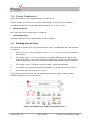
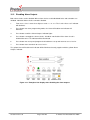
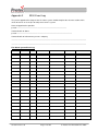
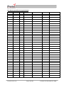
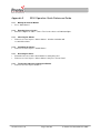
3200 NON-ADDRESSABLE
FIRE ALARM CONTROL PANEL
USER MANUAL
Protec Fire Detection PLC, Protec House, Churchill Way, Nelson, Lancashire, BB9 6RT.
Telephone:
Fax:
Web:
Email:
+44 (0) 1282 717171
+44 (0) 1282 717273
www.protec.co.uk
[email protected]
Document Revision Details
Issue
0
Modification Detail
Document Creation
93-330-72 Issue 0
Page 2 of 20
Author
Date
NH
23/06/05
© Protec Fire Detection PLC 2005
Table of Contents
1.0
INTRODUCTION ..................................................................................................................................................... 4
2.0
USER RESPONSIBILITIES .................................................................................................................................... 5
2.1
3.0
ROUTINE TESTING OF THE SYSTEM. ................................................................................................................. 6
3.1
3.2
3.3
3.4
3.5
3.6
4.0
TESTING THE INDICATIONS (LAMP TEST) ......................................................................................................... 9
SYSTEM FIRE INDICATIONS ................................................................................................................................ 9
6.1
6.2
6.3
6.4
7.0
ACCESS LEVEL 1 (GENERAL USER).................................................................................................................. 7
ACCESS LEVEL 2 (AUTHORISED USER) ............................................................................................................ 7
INDICATIONS AND CONTROLS ........................................................................................................................... 8
5.1
6.0
DAILY INSPECTION .......................................................................................................................................... 6
WEEKLY TEST.................................................................................................................................................. 6
MONTHLY TEST ............................................................................................................................................... 6
QUARTERLY TEST ............................................................................................................................................ 6
ANNUAL TEST .................................................................................................................................................. 6
5 YEARLY TEST ............................................................................................................................................... 7
ACCESS LEVELS ................................................................................................................................................... 7
4.1
4.2
5.0
REQUIREMENTS OF THE APPOINTED RESPONSIBLE PERSON ............................................................................. 5
‘GENERAL FIRE’ INDICATOR ILLUMINATED ..................................................................................................... 9
‘MCP FIRE’ INDICATOR ILLUMINATED ............................................................................................................ 9
FIRE ZONES FLASHING ..................................................................................................................................... 9
FIRE ZONES STEADY ........................................................................................................................................ 9
FAULT INDICATIONS........................................................................................................................................... 10
7.1
7.2
7.3
7.4
7.5
ZONE FAULTS ................................................................................................................................................ 10
SYSTEM FAULTS ............................................................................................................................................ 10
ALARM FAULTS ............................................................................................................................................. 10
POWER SUPPLY FAULTS ................................................................................................................................. 10
AUX 24V. FAULT ........................................................................................................................................... 10
8.0
COINCIDENCE ZONES ........................................................................................................................................ 11
9.0
RESPONSE TO AN ALARM ................................................................................................................................. 12
9.1
9.2
9.3
9.4
9.5
9.6
10.0
SYSTEM DISABLEMENTS................................................................................................................................... 13
10.1
10.2
11.0
AUTOMATIC DETECTION ................................................................................................................................ 12
MANUAL DETECTION ..................................................................................................................................... 12
SILENCING THE ALARMS ................................................................................................................................ 12
RESETTING AFTER AN ALARM ....................................................................................................................... 12
NEW ZONE INTO ALARM ................................................................................................................................ 12
ACTIVATING THE ALARMS MANUALLY ......................................................................................................... 12
DISABLING DETECTOR ZONES ....................................................................................................................... 13
DISABLING ALARM OUTPUTS ........................................................................................................................ 14
TESTING DETECTION ZONES ............................................................................................................................ 15
11.1
PROGRAMMING A ZONE INTO TEST MODE ..................................................................................................... 15
APPENDIX 1
3200 SYSTEM SET-UP RECORD ....................................................................................................... 16
APPENDIX 2
3200 EVENT LOG ................................................................................................................................ 17
APPENDIX 2
3200 EVENT LOG ................................................................................................................................ 17
APPENDIX 3
3200 OPERATION QUICK REFERENCE GUIDE ................................................................................ 19
93-330-72 Issue 0
Page 3 of 20
© Protec Fire Detection PLC 2005
1.0
Introduction
The Protec 3200 Fire Alarm Control Panel has been designed to comply with European Standards
EN54 parts 2 and 4.
The Protec 3200 is also capable of distinguishing between automatic (Detector) and manual (Call
Point) zone activation. The panel takes the appropriate action based on the type of alarm activation.
The Protec 3200 constantly monitors all detector and sounder circuits. The internal power supply
regularly performs internal checks ensuring correct operation. The standby batteries are monitored for
charge and condition.
Any faults detected are reported via the front panel display. A fault output is provided for connection to
external equipment.
The Appendices of this manual include a system set up sheet and an example event log.
The system set up sheet is completed by the commissioning engineer prior to system hand over. The
system set up sheet details exactly how the system has been set up and programmed. It will probably
be the only such record and should be kept in a safe place.
The event log must be completed by the authorised user of the system whenever a Fire or Fault event
occurs. It is advisable to make copies of the example event log to continue the log once the included
sheet has been filled.
Important Note:
There are no user serviceable parts within the Protec 3200 panel. All internal maintenance work
MUST be carried out by a competent person trained to undertake such work.
A separate Installation, Commissioning and Maintenance Manual is available.
This product has been manufactured in conformance with the requirements of all applicable EU
council directives.
93-330-72 Issue 0
Page 4 of 20
© Protec Fire Detection PLC 2005
2.0
User Responsibilities
The registered owner of the fire alarm system has specific responsibilities regarding the installation,
testing and maintenance of the fire alarm system.
BS5839 Pt 1: 2002 states that the owner of the fire alarm system must appoint a single, named,
person to supervise all matters regarding the fire alarm system.
The following is a brief summary of the appointed persons responsibilities.
2.1
Requirements of the Appointed Responsible Person
•
Check the fire alarm equipment at least every 24 hours ensuring there are no faults on the system
or report any faults to the site maintenance manager.
•
Ensure that arrangements are in place for testing the fire alarm system as specified in BS5839 Pt
1 : 2002 Section 6. (Summarised in section 3.0 of this manual).
•
Ensure that the system event log is kept up to date and is available for inspection by any
authorised person. An example event log is included in Appendix 2.
•
Ensure that all occupants of the protected premises are trained how to use the system properly
and that they are aware of what action to take in the event of an alarm.
•
Ensure that false alarms are minimised.
•
Ensure all detectors and manual call points remain un-obstructed. Detectors must have at least
500mm clear space preserved in all directions around them.
•
Ensure that six spare manual call point frangible elements (glass fronts) and appropriate fitting
tools are available as replacements for use in the event a manual call point is activated.
Important Note:
It is advised that a full copy of BS5839 Pt 1: 2002 is obtained and thoroughly read and
understood.
93-330-72 Issue 0
Page 5 of 20
© Protec Fire Detection PLC 2005
3.0
Routine Testing of the System.
Recommendations for testing of the system are detailed in BS5839 Pt 1: 2002 (Section 6).
Routine testing is outlined below:
3.1
Daily Inspection
•
Check that the ‘Supply Present’ indicator is illuminated.
•
Check for any faults on the system and report these to the site maintenance manager.
3.2
Weekly Test
•
Perform an indicator test (Lamp Test) to check the integrity of the front panel indications, and
internal buzzer. See Section 5.1
•
Ensure no manual call points or detectors are obstructed.
•
Operate a manual call point or detector during normal working hours to ensure the fire alarm
system operates correctly. See Section 11 if it is required to place the zone in ‘Test Mode’ for the
duration of the test
•
A different manual call point or detector on a different zone should be tested each week, thus
testing all the devices over a period of time.
•
Ensure the system sounders are operational.
•
Ensure the sounders are operated for a minimum amount of time during testing. Genuine alarms
can then be distinguished by the occupants of the building.
3.3
Monthly Test
•
Perform the weekly test recommended in 3.2.
•
If an automatic generator is used as part of the mains failure back-up system it should be started
up once each month by simulated failure of the normal power supply, and then run in this mode for
at least 1 hour.
•
Visually inspect the stand-by batteries and their connections. Check that the batteries are capable
of supplying the alarm sounders.
3.4
Quarterly Test
•
Perform the monthly test recommended in 3.3.
•
Ensure the system event log is up to date and correct. Check that all faults noted have been
attended to.
3.5
•
•
Annual Test
Perform the Quarterly test recommended in 3.4.
Test every detector, manual call point and all auxiliary equipment for correct functionality.
93-330-72 Issue 0
Page 6 of 20
© Protec Fire Detection PLC 2005
3.6
•
•
5 Yearly Test
Perform the Annual test recommended in 3.5.
Carry out a full wiring check in accordance with the testing and inspection requirements of the
relevant National wiring regulations (I.E.E regulations for the UK).
4.0
Access Levels
The 3200 has two access or authorisation levels for the user, allowing different functions.
4.1
Access Level 1 (General User)
Access level 1 allows the general user to view the status at any time. Zone Fire and Fault states are
displayed together with any current system faults or disablements.
Details of the front panel display are given in Section 5.
The following functions can be performed at Access Level 1.
•
•
•
4.2
Muting the internal buzzer.
Accepting current fire and fault conditions
Entering the Access Level 2 code.
Access Level 2 (Authorised User)
Access level 2 allows the authorised user access to critical system functions. To enter access level 2
from access level 1:
1)
On ‘Code Entry’ models – Enter the code 1 3 4 4 2
2)
On ‘Key Switch’ models – Turn the key
When the correct code has been entered, or the key-switch has been turned the
‘Level 2 Accessed’ indicator lights, showing that level 2 functions are available.
To return back to access level 1, press button 4, or return the key-switch back to its normal position.
NOTE: As a security measure ‘Code Entry’ models will leave level 2 if no key activity has been
detected for 2 minutes.
The following functions can be performed at access level 2.
•
•
•
•
•
•
•
Silencing an alarm condition.
Sounding the alarms.
Resetting the panel after an alarm activation.
Testing the front panel indications and internal buzzer.
Programming a zone into test mode.
Disabling detector circuits.
Disabling alarm circuits.
93-330-72 Issue 0
Page 7 of 20
© Protec Fire Detection PLC 2005
5.0
Indications and Controls
A comprehensive front panel display enables the state of the 3200 to be rapidly determined by
inspection of the indications.
•
Zone Fires are displayed on the indicators on the top left of the front panel.
•
Zone Fault
Zone indicator flashing + ‘General Fault’ indicator,
Zone Disabled
Zone indicator steady + ‘General Disablement’ indicator and
Zone in Test
Zone indicator steady + ‘General Test’ indicator
are all displayed on the top right of the front panel.
•
General Fire indications (automatic and MCP), Access Level, General Test and Alarms Silenced
indications are given on row 3 of the display.
•
System Disablements and System Faults are displayed on row 4 of the front panel display.
Zone Fire Indications
Zone
Fault (flashing)
Disabled (steady)
Test (steady)
System Disablement Indications
Push Buttons
For:
a) Code entry
b) Lamp test
c) Programming
System Fault Indications
Access level indications
Figure 5.0 Front panel Indications and controls
93-330-72 Issue 0
Page 8 of 20
© Protec Fire Detection PLC 2005
5.1
Testing the Indications (Lamp Test)
To test the functionality of the front panel indicators:
1.
At access level 1 enter the 5 digit user code 1 3 4 4 2 or turn the key switch. The ‘Level 2
accessed’ indicator will light.
2.
Press button ‘1’. The 3200 will light all its indicators and sound the internal buzzer.
3.
Confirm that each indicator operates and that the buzzer can be heard clearly.
Inform the site maintenance manager of any problem as soon as possible.
6.0
System Fire Indications
The 3200 displays fire information on the upper left of the front panel display.
6.1
‘General Fire’ Indicator Illuminated
A Fire has been detected on a zone, or an activation has been detected from external
equipment, via the ‘Remote Alarm’ input.
The building fire plan should be executed immediately.
6.2
‘MCP Fire’ Indicator Illuminated
A manual call point has been activated on one of the detection zones. This will always be
accompanied by the ‘General Fire’ indicator and the relevant zone indicator.
6.3
Fire Zones Flashing
A Fire has been detected in the relevant zone. This will always be accompanied by the
‘General Fire’ indicator.
6.4
Fire Zones Steady
A Fire has been detected in the relevant zone and has been accepted by a user pressing the
‘Mute Buzzer’ button.
93-330-72 Issue 0
Page 9 of 20
© Protec Fire Detection PLC 2005
7.0
Fault Indications
When a fault is detected in the critical operating path of the system, it will display this on the front
panel display. The internal buzzer will also pulse slowly.
The ‘General Fault’ indicator will illuminate, together with some other indicator that details the fault.
In general, fault indicators flash until the fault is accepted (pressing the ‘Mute Buzzer’ button), the fault
indicator then lights steady and the internal buzzer is muted. Further faults reactivate the buzzer.
In the event of any fault the following action should be taken:
•
•
Mute the fault buzzer by pressing the ‘Mute Buzzer’ button on the panel.
Note the fault down in the log book and take action to remedy the fault. In all cases expert
advice should be sought.
When the fault has been rectified the fault indicator will automatically extinguish.
7.1
Zone Faults
Faults on the detection zones are shown on the upper right of the display. The ‘General Fault’
indicator will be illuminated accompanied by the relevant zone indicator. Pressing ‘Mute Buzzer’ mutes
the buzzer but WILL NOT make the zone indicator go steady.
7.2
System Faults
The 3200 performs many self tests to ensure the software is working correctly.
The fault should be cleared by pressing ‘Silence Alarms’ then ‘Reset Panel’ whilst in access level 2.
If the fault re-occurs with 3 minutes the 3200 has a microprocessor fault, and the maintenance
manager must be alerted.
7.3
Alarm Faults
A fault has been detected on one or more of the two sounder outputs. One or more of the sounder
circuits may no longer operate correctly.
7.4
Power Supply Faults
A fault has been detected in the power supply module. This may be due to a local mains supply failure
or because the stand-by batteries or charger are faulty.
7.5
Aux 24V. Fault
A fault has been detected with the Auxiliary 24V supply output of the panel.
93-330-72 Issue 0
Page 10 of 20
© Protec Fire Detection PLC 2005
8.0
Coincidence Zones
During commissioning, detection zones may have been programmed as ‘coincidence’ zones. This
means that both of the zones must activate before the alarms sound or the Global Fire Contacts
activate. Manual Call Point activation on either zone overrides the coincidence programming.
If one zone is triggered the cause of the activation must be investigated, if no action is taken within 2
minutes the alarms will sound and the Global Fire contacts will activate.
If the cause of the alarm is deemed false, the 3200 should be reset.
To determine if coincidence zones have been programmed into the system, consult the system set-up
chart (Appendix 1).
93-330-72 Issue 0
Page 11 of 20
© Protec Fire Detection PLC 2005
9.0
Response To An Alarm
9.1
Automatic Detection
If a Smoke or Heat Detector operates on a zone, it is known as an ‘Automatic Operation’. The 3200
responds by:
•
•
•
•
•
9.2
Illuminating the ‘General Fire’ indicator.
Flashing the relevant zone fire indicator.
Fast pulsing the internal buzzer.
Activating non-disabled alarm outputs.
Activating the Global Fire contacts.
Manual Detection
If a Manual Call Point is operated on a zone, it is known as a ‘Manual Operation’. The 3200 responds
by:
•
•
•
•
•
•
•
9.3
Illuminating the ‘General Fire’ indicator.
Illuminating the ‘MCP Fire’ indicator.
Flashing the relevant zone fire indicator.
Fast pulsing the internal buzzer.
Activating non-disabled alarm outputs (immediately).
Activating the Global Fire contacts.
Re-sounding the alarms if the zone had a previously silenced automatic operation.
Silencing the Alarms
The alarms and internal buzzer are silenced by pressing ‘Silence Alarms’ in access level 2.
9.4
Resetting After an Alarm
After the cause of the alarm has been determined (and entered in the log by the authorised user) the
event is reset, if required. In access level 2, press ‘Silence Alarms’ then press ‘Reset Panel’. This
resets any latched detectors on the zone connections. Manual Call Points must be reset manually.
9.5
New Zone into Alarm
If a new zone goes into alarm or a previously silenced zone (triggered by an automatic device) has a
manual activation, the alarms and the internal buzzer will re-sound.
9.6
Activating The Alarms Manually
To evacuate the building press ‘Sound Alarms’ in access level 2. The alarm outputs will activate, but
the Global Fire Contacts WILL NOT be activated.
93-330-72 Issue 0
Page 12 of 20
© Protec Fire Detection PLC 2005
10.0 System Disablements
Various disablements can be programmed by the authorised user.
In some situations it may be useful to ‘turn off’ certain functions to suit specific site conditions.
The following disablements can be made by the authorised user, at access level 2.
•
Zone Disablements
Fires and Faults from the disabled zone are inhibited.
•
Alarm Disablements
Activations and Faults from the disabled alarm circuit are inhibited.
10.1
Disabling Detector Zones
One or both of its detector zones can be disabled. When a zone is disabled both faults and activations
are inhibited.
1.
From access level 1 enter the 5 digit user code 1 3 4 4 2. The ‘Level 2 Accessed’ indicator
will illuminate.
2.
Press button 2 once – The ‘General Disablement’ indicator will illuminate to show the zone
disablement option is selected (the normal front panel display is temporarily replaced with the
programming display). Any current disablements will be displayed on the zone fire indicators.
3.
Press button 1 (zone 1) or button 2 (zone 2) to toggle - disabled / not disabled.
4.
Press button 4 to accept and program the disablement set-up and return to access level 2.
5.
Press button 4 to return back to access level 1.
The yellow ‘General Disablement’ indicator will be illuminated steady, together with the yellow
disablement indicator for the relevant zone(s).
Figure 10.0. Example of the display when disabling zone 1.
93-330-72 Issue 0
Page 13 of 20
© Protec Fire Detection PLC 2005
10.2
Disabling Alarm Outputs
Both alarm circuits can be disabled. When alarm circuits are disabled both faults and activations are
inhibited. Individual Alarm circuits cannot be disabled.
1.
From access level 1 enter the 5 digit user code 1 3 4 4 2. The ‘Level 2 Accessed’ indicator
will illuminate.
3.
Press button 2 to enter programming mode, the 'General Disablement' indicator will
illuminate.
4.
Press button 3 until the 'Alarm Outputs' indicator lights.
5.
Press button 1 to toggle the alarm circuits - disabled / not disabled. If the alarm circuit is
disabled the zone 1 fire indicator will be illuminated.
6.
Press button 4 to accept and program the disablement set-up and return to access level 2.
7.
Press button 4 to return back to access level 1.
The yellow ‘General Disablement’ indicator will be illuminated steady, together with the yellow ‘Alarm
Outputs’ indicator.
Figure 10.1. Example of the display when disabling the alarm outputs.
93-330-72 Issue 0
Page 14 of 20
© Protec Fire Detection PLC 2005
11.0 Testing Detection Zones
To aid the required fire alarm test schedule, zones can be put into ‘test mode’. In this mode, an alarm
on the test zone activates the alarm outputs for 4 seconds then automatically resets. This allows a
zone of detectors to be tested without having to manually reset the panel after each activation.
The Global Fire Contacts are not activated when the test zone goes into alarm.
Alarms on non-test zones will prevent the automatic reset.
11.1
Programming a Zone into Test Mode
The procedure for programming a zone into test is given below.
1.
From access level 1 enter the 5 digit user code 1 3 4 4 2. The ‘Level 2 Accessed’ indicator
will illuminate.
2.
Press button 2 to enter programming mode, the 'General Disablement' indicator will illuminate.
3.
Press button 3 until the 'General Test' indicator lights. Any zones currently in test mode will be
displayed on the zone fire indicator.
4.
Press button 1 (zone 1) or button 2 (zone 2) to toggle - test mode / not in test mode.
5.
Press button 4 to accept and program the disablement set-up and return to access level 2.
6.
Press button 4 to return back to access level 1.
The yellow ‘General Test’ indicator will be illuminated steady, showing that at least one zone has been
programmed into test mode. Any zones programmed into test mode will have their test indicator
illuminated steady.
Important Note:
• Ensure zones are removed from test mode when testing of the system is
complete.
Figure 10.2. Example of display when programming zone 2 into test mode.
93-330-72 Issue 0
Page 15 of 20
© Protec Fire Detection PLC 2005
Appendix 1
3200 System Set-Up Record
This sheet must be completed by the engineer in charge of commissioning the system. It is the only
record of how the system has been configured and, as such, should be safely stored for future
reference.
ZONE
ZONE DESCRIPTION / LOCATION
PROGRAMMING
CONNECTED TO
RESULT
1
2
CONNECTION
Global Fault
Global Fire
Class Change
Remote Alarm
COMMISSIONING DETAILS
System Commissioned By:
Date:
Company:
Contact Details:
93-330-72 Issue 0
Page 16 of 20
© Protec Fire Detection PLC 2005
Appendix 2
3200 Event Log
The person appointed in charge of the fire alarm system should complete the relevant section of this
sheet whenever an event (fire or fault) occurs on the system.
Name of appointed responsible
person……………………………………………………………………………….
Contact details of above
person………………………………………………………………………………………..
Contact details of maintenance person / company
……………………………………………………………………………………………………………………….
……………………………………………………………………………………………………………………….
Fire Alarm System Event Log
DATE
TIME
93-330-72 Issue 0
ZONE
DETAILS
ACTION REQUIRED
Page 17 of 20
COMPLETED
NAME
© Protec Fire Detection PLC 2005
Fire Alarm System Event Log (continued)
DATE
TIME
93-330-72 Issue 0
ZONE
DETAILS
ACTION REQUIRED
Page 18 of 20
COMPLETED
NAME
© Protec Fire Detection PLC 2005
Appendix 3
3200 Operation Quick Reference Guide
14.1
Muting the Internal Buzzer
• Press ‘Mute Buzzer’
14.2
Entering Access Level 2
• Enter the 5 digit user code 1 3 4 4 2. The ‘Level 2 Accessed’ indicator lights.
14.3
Silencing the Alarms
• From access level 2 press ‘Silence Alarms’. A further activation will
re-sound the alarms.
14.4
Sounding the Alarms
• From access level 2 press ‘Sound Alarms’.
14.5
Resetting the Panel
• Determine the cause of the alarm before resetting the panel
• From access level 2 press ‘Silence Alarms’ then press ‘Reset Panel’.
14.6
Testing the Indicators and Internal Buzzer
• From access level 2 press button ‘1’.
93-330-72 Issue 0
Page 19 of 20
© Protec Fire Detection PLC 2005
Protec Fire Detection PLC, Protec House, Churchill Way, Nelson, Lancashire, BB9 6RT.
Telephone:
Fax:
Web:
Email:
+44 (0) 1282 717171
+44 (0) 1282 717273
www.protec.co.uk
[email protected]
93-330-72 Issue 0
Page 20 of 20
© Protec Fire Detection PLC 2005