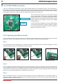
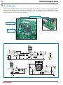
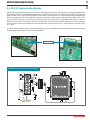
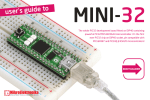
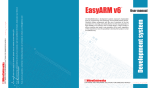
1
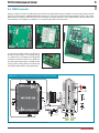
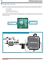
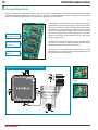
All MikroElektronika´s development systems represent irreplaceable tools for
programming and developing microcontroller-based devices. Carefully chosen
components and the use of machines of the last generation for mounting and
testing thereof are the best guarantee of high reliability of our devices. Due to
simple design, a large number of add-on modules and ready to use examples,
all our users, regardless of their experience, have the possibility to develop
their project in a fast and efficient way.
User manual
Development System
If you have any questions, comments or business proposals, do not hesitate to contact us at [email protected]
If you are experiencing some problems with any of our products or just need additional information, please place your ticket at
www.mikroe.com/en/support
If you want to learn more about our products, please visit our website at www.mikroe.com
PICPLC4 v6
™
DISCLAIMER
All the products owned by MikroElektronika are protected by copyright law and international copyright treaty.
Therefore, this manual is to be treated as any other copyright material. No part of this manual, including
product and software described herein, may be reproduced, stored in a retrieval system, translated or
transmitted in any form or by any means, without the prior written permission of MikroElektronika. The
manual PDF edition can be printed for private or local use, but not for distribution. Any modification of this
manual is prohibited.
TO OUR VALUED CUSTOMERS
I want to express my thanks to you for being interested in our products and for having confidence in
mikroElektronika.
The primary aim of our company is to design and produce high quality electronic products and to constantly
improve the performance thereof in order to better suit your needs.
Nebojsa Matic
General Manager
MikroElektronika provides this manual ‘as is’ without warranty of any kind, either expressed or implied,
including, but not limited to, the implied warranties or conditions of merchantability or fitness for a particular
purpose.
MikroElektronika shall assume no responsibility or liability for any errors, omissions and inaccuracies that may
appear in this manual. In no event shall MikroElektronika, its directors, officers, employees or distributors be
liable for any indirect, specific, incidental or consequential damages (including damages for loss of business
profits and business information, business interruption or any other pecuniary loss) arising out of the use
of this manual or product, even if MikroElektronika has been advised of the possibility of such damages.
MikroElektronika reserves the right to change information contained in this manual at any time without prior
notice, if necessary.
HIGH RISK ACTIVITIES
The products of MikroElektronika are not fault – tolerant nor designed, manufactured or intended for use or
resale as on – line control equipment in hazardous environments requiring fail – safe performance, such as
in the operation of nuclear facilities, aircraft navigation or communication systems, air traffic control, direct
life support machines or weapons systems in which the failure of Software could lead directly to death,
personal injury or severe physical or environmental damage (‘High Risk Activities’). MikroElektronika and its
suppliers specifically disclaim any expressed or implied warranty of fitness for High Risk Activities.
TRADEMARKS
The Mikroelektronika name and logo, the Mikroelektronika logo, mikroC, mikroC PRO, mikroBasic, mikroBasic PRO, mikroPascal, mikroPascal PRO, AVRflash, PICflash, dsPICprog, 18FJprog, PSOCprog, AVRprog, 8051prog, ARMflash, EasyPIC5, EasyPIC6, BigPIC5, BigPIC6, dsPIC PRO4, Easy8051B, EasyARM,
EasyAVR5, EasyAVR6, BigAVR2, EasydsPIC4A, EasyPSoC4, EasyVR Stamp LV18FJ, LV24-33A, LV32MX,
PIC32MX4 MultiMedia Board, PICPLC16, PICPLC8 PICPLC4, SmartGSM/GPRS, UNI-DS are trademarks
of Mikroelektronika. All other trademarks mentioned herein are property of their respective companies.
All other product and corporate names appearing in this manual may or may not be registered trademarks
or copyrights of their respective companies, and are only used for identification or explanation and to the
owners’ benefit, with no intent to infringe.
The Microchip name and logo, the Microchip logo, Accuron, dsPIC, KeeLoq, microID, MPLAB, PIC, PICmicro, PICSTART, PRO MATE,
PowerSmart, rfPIC and SmartShunt are registered trademarks of Microchip Technology Incorporated in the U.S.A and other countries.
©MikroelektronikaTM, 2010, All Rights Reserved.
3
page
PICPLC4 v6 Development System
TABLE OF CONTENTS
Introduction to PICPLC4 v6 Development System .......................................................................... 4
Key Features .................................................................................................................................... 5
1.0. PIC18F87J60 Microcontroller ................................................................................................... 6
2.0. Programming the Microcontroller .............................................................................................. 6
3.0. Power Supply ........................................................................................................................... 8
4.0. RS-232 Communication Module ............................................................................................... 9
5.0 Ethernet Module ........................................................................................................................ 10
6.0 GSM Connector ........................................................................................................................ 11
7.0. Real-Time Clock (RTC) ............................................................................................................. 12
8.0. Relays ....................................................................................................................................... 13
9.0. I/O Ports .................................................................................................................................... 14
MikroElektronika
page
4
PICPLC4 v6 Development System
Introduction to PICPLC4 v6 Development System
The PICPLC4 v6™ development system provides a development environment for experimenting with industrial devices. Connection
between the development system and these devices is established by means of relays. In addition, the PICPLC4 v6 features
additional modules which also enable the microcontroller to be connected to external devices. The PICPLC4 v6 may be used as a
stand-alone controller which communicates to remote devices through communication modules. Numerous modules, such as RS232 communication module, real-time clock, ethernet controller, GSM module etc. are provided on the board and allow you to easily
experiment with your microcontroller.
Development system may be
used as a stand-alone controller
in industrial devices
Development system for PIC
microcontroller based devices
Built-in microcontroller provided
on the board is programmed by
means of the external 18FJprog™
programmer
Connection to remote PCs is established via
LAN network and a built-in module for ethernet
communication
Owing to the GSM module it is possible to establish
communication between the development system
and other devices which use GSM standard
The Lv18PICflash™ program provides a complete list of all supported
microcontrollers. The latest version of this program with updated list of supported
microcontrollers can be downloaded from our website at www.mikroe.com
Package contains:
Development system:
CD:
Cables:
Documentation:
PICPLC4 v6
product CD with relevant software
USB cable
Manual for PICPLC4 v6, quick guide for installing USB
drivers and electrical schematic of the development
system
System specification:
Power supply:
Power consumption:
Dimension:
Weight:
MikroElektronika
over the CN1 connector (12-22V AC or 16-30V DC)
~20mA when all on-board modules are off
21,4 x 14cm (8,4 x 5,5inch)
~300g (0.65lbs)
5
page
PICPLC4 v6 Development System
1
2
3
4
5
6
7
8
9
17
10
16
15
Key Features
1.
2.
3.
4.
5.
6.
7.
8.
Power supply connector CN1
Power supply voltage regulator
Ethernet module
RS-232 communication module
Connector for speaker
Connector for microphone
I/O port connectors
Jumper for pull-up/pull-down resistor selection
14
13
12
11
9. PIC18F87J60 microcontroller
10. DIP switch to enable pull-up/pull-down resistors
11. CN8 connector for external programmer
12. DIP switches to enable/disable on-board modules
13. Connector for GSM module
14. Real-time clock
15. Connectors for relays
16. Relays
17. Connector for GSM antenna
MikroElektronika
page
6
PICPLC4 v6 Development System
1.0. PIC18F87J60 Microcontroller
There is a PIC18F87J60 microcontroller in 80-pin TQFP package soldered on the development system. This microcontroller is
provided with an on-board ethernet module which enables connection between the development system and LAN (local area network)
over the ethernet connector. In addition to the ethernet module, the microcontroller also features other modules intended for USART
communication, PWM control, serial communication, parallel communication, A/D conversion etc.
Quartz crystall oscillator
PIC18F87J60
Microcontroller
The PIC18F87J60 microcontroller can communicate to external
devices via either SPI or I2C connection, whereas the USART
module enables it to be connected to two communication modules
RS-232 and RS-485. The microcontroller also features a 10-bit
analog to digital converter capable of using up to 16 available
channels (I/O pins).
For the clock frequency stabilization, the microcontroller employs
an external quartz crystal with a frequency of 25MHz. In addition
to it, the microcontroller also features an internal clock frequency
stabilizer with a frequency of 31kHz.
Figure 1-1: PIC18F87J60 microcontroller
2.0. Programming the Microcontroller
In order to enable the microcontroller provided on the development system to be programmed, it is necessary to provide an external
programmer 18FJprog. This programmer is placed over a 2x5 male connector CN8 on the development system.
Step 1:
Prior to starting the process of programming, it is necessary to connect the development system to the power supply source. Follow
the instructions given in figure 2-1 to establish this connection properly.
1
2
Figure 2-1: Connecting power supply source
3
Figure 2-2: Power supply
Step 2:
Prior to connecting the 18FJprog external programmer, the appropriate driver necessary for the proper operation of this programmer
must be installed. In addition, it is also necessary to install the Lv18PICflash program used for loading a .hex file from the PC to the
microcontroller. The driver and the Lv18PICflash program are provided on the product CD that you get along with the development
system. They can also be downloaded from our website at www.mikroe.com
Step 3:
When the development system is connected to the power supply source and the appropriate driver is successfully installed, it is
necessary to place a 2x5 female connector provided on the 18FJprog programmer on the 2x5 male connector CN8 provided on the
development system, as shown in Figure 2-3.
MikroElektronika
7
2
1
3
page
PICPLC4 v6 Development System
4
Figure 2-3: Connecting programmer
When the external programmer 18Fjprog is connected to the development system, it is necessary to connect it to a PC via USB cable.
One end of the cable with a connector of the USB A type should be connected to a PC, whereas the other end of the cable provided
with a connector of the USB B type should be connected to the programmer.
Figure 2-4: 18FJprog programmer connected to the development system
During the programming, the programmer is used for loading a hex. file into the microcontroller via RB6, RB7 and MCLR microcontroller
pins. When the programmer is connected to the development system, these pins cannot be used as I/O pins since they are used
for programming. In order to use them as I/O pins, it is necessary to place jumpers over the pins of the 2x5 male connector CN8, as
shown in Figure 2-3 (4).
Figure 2-5: 18FJprog programmer
MikroElektronika
page
8
PICPLC4 v6 Development System
3.0. Power Supply
The PICPLC4 v6 development system is connected to the power supply source via the CN1 connector. The power supply voltage can
be either DC or AC. A DC power supply voltage can be in the range of 16V to 30V, whereas the AC power supply voltage can range
between 12V and 22V. Have in mind that the on-board programmer cannot operate without being connected to the power supply
source although it is connected to a PC via the USB cable.
Power supply connector CN1
POWER SUPPLY switch
Power supply voltage
regulator
Figure 3-1: Power supply
Figure 3-2: Power supply connection schematic
MikroElektronika
9
page
PICPLC4 v6 Development System
4.0. RS-232 Communication Module
USART (Universal Synchronous/Asynchronous Receiver/Transmitter) is one of the most common ways of exchanging data between the
PC and peripheral units. The RS-232 serial communication is performed through CN17 and CN18 connectors and the microcontroller
USART module. There is one RS-232 port provided on the PICPLC4 v6. Use switches 4-7 on the DIP switch SW5 to enable this port.
Which of these switches is to be used depends on the microcontroller pin which is fed with an RS-232 communication signal. In case
pins RC7 and RC6 are used, it is necessary to set switches 4 (RX) and 6 (TX) on the DIP switch SW5 to ON position. In case pins
RG2 and RG1 are used, it is necessary to set switches 5 (RX) and 7 (TX) on the DIP switch SW5 to ON position. The microcontroller
pins used for the RS-232 communication are marked as follows: RX - receive data line and TX - transmit data line. Data rate goes up
to 115 kbps.
In order to enable the USART module of the microcontroller to receive input signals which meet the RS-232 standard, it is necessary
to adjust voltage levels using an IC circuit such as MAX3238E.
RS-232 connector
Figure 4-1: RS-232 module
Port RS-232 is connected to the microcontroller
Figure 4-2: RS-232 module connection schematic
MikroElektronika
page
10
PICPLC4 v6 Development System
5.0. Ethernet Module
The function of the ethernet connector provided on the PICPLC4 v6 development system is to connect it to LAN. Ethernet
communication is enabled on the development system owing to the ethernet module built into the PIC18F87J60 microcontroller. The
ethernet connector and the microcontroller are connected via the following microcontroller pins TPOUT+, TPOUT-, TPIN+ and TPIN-.
By placing jumpers J5 and J6, LEDs marked as LEDA and LEDB will be enabled. These two LEDs are used to indicate whether the
ethernet module is active during communication between the microcontroller and some other device connected to LAN.
Ethernet module connector
Figure 5-1: Ethernet module
Ethernet module is connected to the microcontroller
Figure 5-2: Ethernet module connection schematic
MikroElektronika
11
page
PICPLC4 v6 Development System
6.0. GSM Connector
Owing to a built-in connector for GSM module, the PICPLC4 v6 development system is capable of communicating with the outside
world using GSM network. A GM862-QUAD GSM module from Telit can be ordered with the development system. This module
features a slot for placing a SIM card as well as a connector for external antenna. For the GSM module to be connected to the
microcontroller, it is necessary to set switches 1-8 on the DIP switch SW6 to the ON position.
Figure 6-1: GSM connector
Figure 6-2: GSM module
In case that the GSM module is employed for
the audio communication, it is necessary to plug
in a speaker and a microphone into appropriate
connectors, as shown in Figure 6-3. In addition to
the audio signal transmission, the GSM module
can be used for sending data in accordance with
the GPRS standard used in mobile applications.
Figure 6-4: GSM module with antenna
Figure 6-3: Audio connectors
GSM module is connected to the microcontroller via DIP switch SW6
Figure 6-5: Microcontroller and GSM connector connection schematic
MikroElektronika
page
12
PICPLC4 v6 Development System
7.0. Real-Time Clock (RTC)
A real-time clock is widely used in alarm devices, industrial controllers, consumer devices etc. As a result of the built-in PCF8583 circuit,
the PICPLC4 v6 development system is capable of keeping the real time. The main features of the real-time clock are as follows:
- clock with calendar
- I2C serial interface
- universal counter used as an alarm
- ability to change the time format (12/24h)
The real-time clock provided on the PICPLC4 v6 development system is used to generate an interrupt at pre-set time. In order to
establish connection between the microcontroller and the real-time clock it is necessary to set switches 1, 2 and 3 on the DIP switch
SW5 to the ON position.
Quartz-crystal provides
accuracy of the clock signal
used by the real-time clock
3V battery enables the operation
of the real-time clock when the
power supply is off
Figure 7-1: Real-time clock
Real-time clock is connected to the microcontroller via pins RC4, RC3 and RB0
Figure 7-2: Real-time clock and microcontroller connection schematic
MikroElektronika
13
page
PICPLC4 v6 Development System
8.0. Relays
Industrial devices usually utilize more power than the microcontroller can provide via its I/O ports. To enable the microcontroller to be
connected to such devices, the development system is provided with 4 relays by means of which it is possible to provide up to 250V
power supply. Each relay has one normally-open (W0, W1...), one normally-closed (NW0, NW1...) contact and one common contact
(COM0, COM1...). These relays are run by the microcontroller.
Connectors for relays
Figure 8-1: Relays with relevant connectors
Relays are connected to the microcontroller via a relay driver ULN2803
Figure 8-2: Relays and microcontroller connection schematic
MikroElektronika
page
14
PICPLC4 v6 Development System
9.0. Input/Output Ports
Along the right side of the development system, there are four 10-pin connectors which are linked to the microcontroller’s I/O ports.
DIP switches SW1-SW4 enable each connector pin to be connected to a pull-up/pull-down resistor. It depends on the position of
jumpers J1-J4 whether the port pins are to be connected to pull-up or pull-down resistors.
Pull-up/pull-down resistors enable you to set the logic level on all
microcontroller’s input pins when they are in idle state. This level
depends on the position of the pull-up/pull-down jumper. When
this jumper is in pull-up position, the input pins will be supplied
with the 3.3V power supply voltage, which means that they will
be driven high (logic one (1)). When this jumper is in pull-down
position, the input pins will be supplied with 0V, i.e. they will be
fed with a logic zero (0).
Jumper for pull-up/pulldown resistor selection
DIP switch to enable pullup/pull-down resistor for
each port pin
In order to provide some of the microcontroller pins with a desired
logic level, it is necessary to enable connection between that pin
and the resistor using the appropriate DIP switch.
PORTH male 2x5
connector
Refer to Figure 9-4. Port PORTC pins are driven low (0). It means
that jumper J3 is in pull-down position, whereas switches on the
DIP switch SW3 are in ON position.
Figure 9-1: I/O ports
Port PORTC pins are connected to pull-down resistors
Figure 9-2: J3 in pull-down
position
Figure 9-3: J3 in pull-up
position
Figure 9-4: Port PORTC connection schematic
MikroElektronika
DISCLAIMER
All the products owned by MikroElektronika are protected by copyright law and international copyright treaty.
Therefore, this manual is to be treated as any other copyright material. No part of this manual, including
product and software described herein, may be reproduced, stored in a retrieval system, translated or
transmitted in any form or by any means, without the prior written permission of MikroElektronika. The
manual PDF edition can be printed for private or local use, but not for distribution. Any modification of this
manual is prohibited.
TO OUR VALUED CUSTOMERS
I want to express my thanks to you for being interested in our products and for having confidence in
mikroElektronika.
The primary aim of our company is to design and produce high quality electronic products and to constantly
improve the performance thereof in order to better suit your needs.
Nebojsa Matic
General Manager
MikroElektronika provides this manual ‘as is’ without warranty of any kind, either expressed or implied,
including, but not limited to, the implied warranties or conditions of merchantability or fitness for a particular
purpose.
MikroElektronika shall assume no responsibility or liability for any errors, omissions and inaccuracies that may
appear in this manual. In no event shall MikroElektronika, its directors, officers, employees or distributors be
liable for any indirect, specific, incidental or consequential damages (including damages for loss of business
profits and business information, business interruption or any other pecuniary loss) arising out of the use
of this manual or product, even if MikroElektronika has been advised of the possibility of such damages.
MikroElektronika reserves the right to change information contained in this manual at any time without prior
notice, if necessary.
HIGH RISK ACTIVITIES
The products of MikroElektronika are not fault – tolerant nor designed, manufactured or intended for use or
resale as on – line control equipment in hazardous environments requiring fail – safe performance, such as
in the operation of nuclear facilities, aircraft navigation or communication systems, air traffic control, direct
life support machines or weapons systems in which the failure of Software could lead directly to death,
personal injury or severe physical or environmental damage (‘High Risk Activities’). MikroElektronika and its
suppliers specifically disclaim any expressed or implied warranty of fitness for High Risk Activities.
TRADEMARKS
The Mikroelektronika name and logo, the Mikroelektronika logo, mikroC, mikroC PRO, mikroBasic, mikroBasic PRO, mikroPascal, mikroPascal PRO, AVRflash, PICflash, dsPICprog, 18FJprog, PSOCprog, AVRprog, 8051prog, ARMflash, EasyPIC5, EasyPIC6, BigPIC5, BigPIC6, dsPIC PRO4, Easy8051B, EasyARM,
EasyAVR5, EasyAVR6, BigAVR2, EasydsPIC4A, EasyPSoC4, EasyVR Stamp LV18FJ, LV24-33A, LV32MX,
PIC32MX4 MultiMedia Board, PICPLC16, PICPLC8 PICPLC4, SmartGSM/GPRS, UNI-DS are trademarks
of Mikroelektronika. All other trademarks mentioned herein are property of their respective companies.
All other product and corporate names appearing in this manual may or may not be registered trademarks
or copyrights of their respective companies, and are only used for identification or explanation and to the
owners’ benefit, with no intent to infringe.
The Microchip name and logo, the Microchip logo, Accuron, dsPIC, KeeLoq, microID, MPLAB, PIC, PICmicro, PICSTART, PRO MATE,
PowerSmart, rfPIC and SmartShunt are registered trademarks of Microchip Technology Incorporated in the U.S.A and other countries.
©MikroelektronikaTM, 2010, All Rights Reserved.
All MikroElektronika´s development systems represent irreplaceable tools for
programming and developing microcontroller-based devices. Carefully chosen
components and the use of machines of the last generation for mounting and
testing thereof are the best guarantee of high reliability of our devices. Due to
simple design, a large number of add-on modules and ready to use examples,
all our users, regardless of their experience, have the possibility to develop
their project in a fast and efficient way.
User manual
Development System
If you have any questions, comments or business proposals, do not hesitate to contact us at [email protected]
If you are experiencing some problems with any of our products or just need additional information, please place your ticket at
www.mikroe.com/en/support
If you want to learn more about our products, please visit our website at www.mikroe.com
PICPLC16 v6
™