1
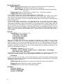
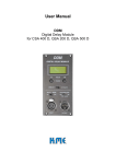
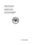
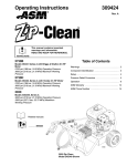
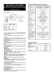
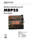
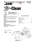
User Manual
DA 428
completely digital 4-channel amplifier
1. Introduction
Thank you for choosing a K.M.E. product!
This completely digital 4-channel amplifier with DSP-functionality is based on a similar
technology-platform like the active units of the VERSIO-series. The exceptional and
ground breaking performance of this digital amplifier allows an optimization within for all
passively driven PA- systems. It provides a loudspeaker specific configuration and
functionality. With this compact and sophisticated amplifier, you will be able to master
your reinforcement situations in a very flexible manner (main-PA, full-range-mode,
monitoring, fill-system, delay line).
In this User Manual you will find some hints and warning notes for your new product with
which a save use of the DA 428 is allowed. Please read this instructions before you
switch on the unit for the first time, to get in touch with particular features of your new
product. If you have questions about this product please contact the K.M.E. support.
Within our extensive production processes we only use exclusive materials and
components of best quality. Share with us the enthusiasm for good sound. The K.M.E.
team wishes you fun and success with your new completely digital DSP-amplifier!
2. Contents
1. Introduction
2. Contents ………...............................................................................
3. The completely digital 4-channel DSP-amplifier .............................
4. The delivery status ………...............................................................
5. The control- and connection panel .................................................
6. Powering up / down - 6.1 choosing preset - play! …………...……..
6.2 selecting presets ………………..............
7. Navigation structure on the hardware unit ......................................
8. Operation ........................................................................................
9. Routing of input channels …...….....................................................
10. Link mode / content of link channels ………..................................
11. Specifications DA 428 ………………………………………………..
12. The most important menu functions - 12.1 mute-function ...…......
12.2 switching input between
analogue or digital .....
12.3 entering password .....
12.4 lock-function ..............
13. System operation and extension ……............................................
14. EC-declaration of conformity .........................................................
15. Disposal of your old appliance ......................................................
2
2
3
3
4-5
6
6
7
8-10
11
12
13
14
14
15
15
16-18
19
20
3. The completely digital 4-channel DSP-amplifier
The DA 428 is a completely digital 4-channel amplifier with 700 W @ 4 ohm output power
on each channel. This compact, light- weight 19"-2U device is equipped with
comprehensive DSP features like matrix router, 6 fully parametric equalizers, two
crossover networks, delay and dynamic processor per channel. All parameters as well as
user navigation can be managed using a simple 5-key navigation pad together with
4 rotary encoders. The sophisticated user interface is completed by a graphic LCD
display and 4 RGB LED`s informing about relevant operation parameters and state of the
single channels.
Factory and user presets may of cause be stored inside the unit, an SD- card reader is
implemented and can be used to easily transfer preset and system information to other
units. An preset editor software and various firmware add- ons are available as well.
On the inputs side are 4 analogue connections as well as 2 digital ports accepting
AES/EBU and SPDIF formats of 16 to 24 bit and 32 to 192 kHz sampling frequency.
4 link sockets, either carrying the signal applied to the inputs can be routed as
“processed” digital outputs carrying AES/EBU of 24 bit / 48 kHz. The designers also
implemented a module slot for future updates, i.e. connections to audio / control
networks, standard- fitted with module RSNC equipped with a RS232 connector and a
´normally closed´ contact feature. Global remote control is guaranteed using future
firmware upgrade modules, but even the standard version contains simple remote
features. Another important feature is the PFC controlled, audio-optimised wide-range
switched- mode power supply of the last generation.
The outside power connection was realised using a self- locking Neutrik PowerCon
connector, 4 Neutrik Speakon sockets (channel A + B are wired ´bi-amp´) ensure the
connection to the speaker systems. An extensive set of protective circuits and digital
monitoring components is included ´´rounding off´´ the professional features of this
equipment. The DA 428 is usable for stage monitor operation to system operation of
passive PA components or realisation of professional multi- channel systems within
sound installations.
4. The delivery status
The scope of delivery includes: 1x DA 428, 1x PowerCon-mains cable, 1x rack-mounting
set, 4x rubber base and user manual
When you power up the DA 428 for the very first time the following default parameters in
the main menu are pre-set:
- „Preset 1“ is loaded
- Sig. LED threshold is adjusted to -50 dB
- User LED threshold is adjusted to 0 dB (0 dB = deactivated)
- output levels are shown on the LCD display
- input A and B are switched to analogue
- a password is not entered
This User Manual corresponds to the software version V1.01 r35.
It is obvious in the menu item „Diagnostics“!
3
5. The control- and connection panel
POWER
SD CARD SLOT
A
B
C
D
DIGITAL USER INTERFACE
3.RGB LED
2.SD-card reader
1.rotary encoder
NAVIGATION
4.LCD-display
5.navigation pad
INPUT
OUTPUT
KLINGENTHALER
MUSIKELEKTRONIK
GmbH
MADE IN GERMANY
DA 428
ANALOG OR DIGITA L
A
ANALOG
B
C
SO URCE OR D- OUT
D
A
B
ERROR
LINE
CONTROL PORT
N.C.
RS 232
pot ent ia l free
LINK
8.ground/free10.link-output
switch
9.LINE-input
7.mains fuse
6.mains connector
4
C
D
SOURCE
I/O OPTIONAL MODULES
11.module slot with
RS/NC-Modul
12.speaker output
13.M8 treads for rack
mounting
Operation
1. rotary encoder with fast turn detection - You can adjust the volume level of each channel
independently. If there is no menu item activated, a short pressing of an encoder effects the
status display of this channel. By pressing the encoder a bit longer, you are muting this channel.
To unmute the channel, press the encoder again for a short time. After unmuting, the volume
level will be set on the level before muted the channel.
All encoders are used for choosing and setting of menu items resp. values, too.
2. SD-card reader - Is the interface to save and load presets from the card. Firmware updates
are also possible with this SD-card reader. You can also transfer user presets by SD-card to copy
it between in a number of devices. The programmed format is FAT16 which is used on computers
to read and write it.
3. RGB LED - Signalized different parameters (per channel):
LED off
- there is no input signal or the device is not on
LED green
- there is an input signal which is higher than the threshold
LED blue
- the adjusted user threshold value is exceeded
LED yellow
- max. input level, the limiter is working
LED red
- there is a malfunction, you have to power cycle the DA 428
LED cyan
- channel is muted
LED white
- encoder will be used for entering of adjustable parameters
LED magenta
- signalized external access (is not used in this version)
4. LCD display - Is used as operation mode display of the DA 428. The arrows in the LCD display
show the directions to navigate through the submenus (see navigation structure). All software
parameters must be set on the unit itself. Press the ‘OK’ button to select a parameter. To change
a value in the submenus please use the four arrow keys or the encoders if you are asked by the
unit.
5. navigation-pad - Here you can switch on / off the DA 428 and navigate through the menu. The
navigation pad is to be used for accessing and changing parameters on the display of the
hardware unit. Press the OK button if you are asked by the software (see navigation structure).
Power
6. mains connector - PowerCon in (blue), Attention: use mains voltage of 90 - 250 V AC /
50 - 60 Hz.
7. mains fuse - Replace fuse only by type 10 AT slow blowing fuse 5x20 mm.
8. ground/free switch - Disconnects the ground of the input channels from chassis to avoid
ground loops.
Inputs / Outputs
9. LINE input - 4x XLR sym., inputs A + B can be switched separately between analogue or
digital (see navigation structure).
10. Link-output - 4x XLR sym., outputs A + B can be switched between analogue or digital (see
navigation structure). The link output of channel A + B can be routed as “processed” digital
outputs carrying AES/EBU of 24 bit / 48 kHz. All link sockets are only active when the DA 428 is
powered on.
11. module slot with RS/NC module - Equipped with a RS232 connector and a ´normally
closed´ contact feature.
12. speaker output - 4x Speakon NL 4 (4x 700 W @ 4 ohms (min. impedance)), output power
depends on preset. Attention: Please mind nominal load and impedance of the passive
loudspeaker(s) you connect. The speaker outputs A + B are interconnected with the outputs
C + D for bi-amp mode (output A: A=1+/1- + C=2+/2- and output B: B=1+/1- + D=2+/2-).
13. M8 treads for rack mounting - 4x M8 treads for 19“ rack mounting
5
6. Powering up / down
To switch on / off your DA 428, please follow the instructions:
1. Apply power supply connection (90 - 250 Volt / 50 - 60 Hz) on DA 428 (if the unit is
switched to power mode „Always On“, it is switched on now) – „lock“-function can be
active!
2. Press for a very short time the OK-button to switch on the DA 428
3. To switch off the DA 428, press for 1 second the left arrow key and than the OK-button.
If the unit is locked, please disconnect the power supply connection to switch off the
DA 428.
Note! Switch on the DA 428 when all connected components are switched on and muted
previously to avoid an unwanted sound reproduction. Because the DA 428 can be in
„lock-function“ for rental purposes that means the unit may not react on changes on the
control panel (depending on adjustment before) and this can cause an immediate
reproduction when switching it on. Therefore it is necessary to mute all connected
devices previously.
During power on for the very first time, Preset 1“ is loaded! More information about the
initial state you can find on page 3.
6.1 Choose your preset - play!
To adapt your completely digital 4-channel amplifier to your reinforcement, you have to
choose and load the correct preset. For selected applications the DA 428 includes some
pre-set presets. If you would choose these presets, please take care of the internal
routing of the signal inputs and speaker outputs of the DA 428 (provided that the input
signal is analogue).
The DA 428 includes 12 factory presets in the internal memory which can be free
programmed and saved on the actually preset. You can change and save the name of
the preset, too. You can save and load factory presets also on SD-card. How to do that
and which changes are possible in the detailed submenu, you will find on page 8 - 10 in
this manual.
6.2 Selecting presets
In the following example you choose „preset 3“, please follow the instructions!
Output headroom info
Bass
Bass
Top L
Top R
→
For menu access
touch knob or panel
Pr 1 Preset 1
2x
Output headroom info
Bass
Bass
Top L
Top R
→
For menu access
touch knob or panel
Pr 3 Preset 3
After power up the DA 428 for the very first time the left graphic appears on the LCD display. Now
„preset 1“ is loaded. For example to choose and load „preset 3“ you have to press the marked
arrow key twice and confirm with the OK-button. If you control your PA system with an analogue
audio signal, you can start now!
6
7. Navigation structure on the hardware unit
Main Menu
Preset
Delay (Out A - D)
0 ... 400 m
Equalizer (Out A - D)
EQ 1+ 6
Frequency
Q
Gain
Shape
35 ... 12000 Hz
00.7 ... 12.5
-12 ... +12 dB
PEQ / Shelf
EQ 2 - 5
Frequency 35 ... 12000 Hz
Q
00.7 ... 12.5
Gain
-12 ... +12 dB
HP Frequency 35 ... 8000 Hz
HP
Subsonic / 12 dB / 24 dB
LP Frequency 35 ... 8000 Hz
LP
Off / 12 dB / 24 dB
Crossover (Out A - D)
Dynamics (Out A - D)
Threshold
Attack
Release
Post Gain
-24 ... 00 dB
0 ... 127 ms
0 ... 1270 ms
-99 ... 0 dB
Polarity (Out A - D)
normal (0°)
inverse (180°)
Routing (Out A - D)
A/d1(L) -- B/d2(L) -- C/d1(R) -- D/d2(R) -C always -- D always -- A+B/d1(L+R) -C+D/d2 (L+R) -- C+D always -- B+C+D -A+B+C+D/d1+d2
Level Groups (Out A - D)
independent
Group 1
Group 2
Mute Groups (Out A - D)
independent
Group 1 strong
Group 1 weak
Group 2 strong
Group 2 weak
Channel Names (Out A - D)
Preset Name
Names
Name
Memory Card
Load preset from card
Save preset to card
Load all from card
Save all to card
Display Mode
Output headroom
Input levels
Diagnostics
LED Settings
Signal LED Threshold (Out A - D)
User LED Threshold (Out A - D)
Power Management
System
Mode
Always On / Last State / Audio Trigger
Trigger Level
-99 ... 0 dB
Trigger Time
1 ... 120 min.
Input Mode (In A - B)
In A analog / In A digital / In A auto detection
In B analog / In B digital / In B auto detection
Link Mode / Content (Link A - B)
Password
Contrast
Software
Source -- A:C/d1 -- B:D/d2 -A+B/d1mono -- C+D/d2mono -C+Dalways -- B+C+D/d2L+C+D -A+B+C+D
Password
RSNC baud rate
Brightness
-60 ... -10 dB
-50 ... 0 dB
1200 / 2400 / 4800 / 9600 / 19200 / 38400 /
57600 / 115200 kbit/s
1 ... 127
1 ... 63
Firmware Version
Firmware Update DSP
Update I²C EEPROM
7
8. Operation
All these software parameters can be set directly on the hardware device or with an
optional software on the computer (transfering the presets by SD card). The names of the
menu items refer to the user navigation on the device.
The menu items
• Preset:
Delay [adjust delay from 0 – 400m for each channel, in 1 cm steps]
Equalizer 1+6 [adjust equalizer per channel]
Frequency
Q (bandwidth)
Gain
Shape
Parametric / Shelf [fully parametrical EQ or Shelf-function]
With this digital filter you can affect the frequency range by making adjustments of filter
frequency (center frequency), the gain (boost resp. cut) and the Q-factor (bandwidth). If you
adjust the sensitivity (gain) to 0 dB you deactivate this filter. If you choose the type “Low Shelf or
High Shelf” the bandwidth is not activated (you can enter a value for the Q-factor but it is
ignored)!
You can use the equalizer 1 as a fully parametrical equalizer or as „Low Shelf“and the equalizer
6 also as fully parametrical equalizer or as „High Shelf“.
Equalizer 2- 5 [adjust equalizer per channel]
Frequency
Q (bandwidth)
Gain
With this digital filter you can affect the frequency range by making adjustments of filter
frequency (center frequency), the gain (boost resp. cut) and the Q-factor (bandwidth). If you
adjust the sensitivity (gain) to 0 dB you deactivate this filter.
Crossover (high pass- / low pass filter) [crossover function per channel]
HP Frequency
Type (subsonic-filter 12 dB Q=1,2 or 12 dB/octave or 24 dB/octave)
LP Frequency
Type (off or 12 dB/octave or 24 dB/octave)
These digital filters (crossover) limit the frequency range. The high pass filter can not be
deactivated. When you need a full-range audio signal on the output you have to set the
frequency to 35 Hz and choose a type of the high pass filter.
Dynamics [adjust dynamics per channel]
Threshold
Attack
Release
Post Gain
This dynamic processor is working when the audio signal exceeds the entered threshold-value.
The two time constants attack and release time draw the speed of the gain regulation
mechanism and are dependent to the program material. With the post gain you can adjust your
audio signal level.
Polarity [adjust output phase for each channel; choose between 0° or 180°]
Routing [routing possibilities for each channel]
A/d1(L), B/d2(L), C/d1(R), D/d2(R), C always, D always,
A+B/d1(L+R), C+D/d2(L+R), C+D always, B+C+D, A+B+C+D/d1+d2
The routing of the DA 428 offers comprehensive possibilities for controlling the audio signal.
You will find detailed information in the table on page 11.
8
Level Groups
Independent [volume is independently adjustable]
Group1 [volume is dependently adjustable of an other channel]
Group2 [see Group 1]
With this function you are able to mute your channel(s) separately or dependently of one or
more channels. For example you can set the channel A and B as group 1 (using a mono signal
for the subs) and the channel C and D as group 2 (using a stereo signal for the top units). While
using this settings you can change the volume for the subwoofer or for the top units by using
only one encoder of each group. For using this function you have to link the single channel(s) to
the group 1 or group 2 If there is a volume difference in the pre-setting between the single
channels (at the time of the linking), the difference still exists in the group. Both groups are
identically functional.
Mute Groups
Independent [mute the channel independently]
Group1 strong [can mute other channels, too]
Group1 weak [can be muted by an other channel and can be muted independently]
Group2 strong [see Group1 strong]
Group2 weak [see Group1 weak]
Here you can mute all single channels separately resp. in dependence of one or more channels.
For example you can select channel A as master (=Group1 strong) and channel B as slave
(=Group1 weak). After this settings you can mute channel A and channel B is muted
automatically, too. If you want to mute only channel B you can do it, because it is independently
switchable.
Channel Names [enter a name for each channel, max. 9 digits]
Preset Name [enter preset name, max. 12 digits]
• Memory Card:
Load Preset from card
Save preset to card
Load all from card [not as yet available in this version]
Save all to card [not as yet available in this version]
In the internal preset memory of the DA 428 you can save 12 presets. On an additional SD-card
you can save or load / copy one preset or all presets from the amplifier to the SD-card or the
other way round. Therefore you have to choose one of the menu items and with the aid of the
navigation pad and the rotary encoder A you can select your preset(s) and confirm with the OKbutton (if necessary a data file name has to be entered). You can leave the menu by pressing
the left arrow key.
• Display Mode:
Output headroom [headroom display]
Input levels [input level display]
Diagnostics [operation display]
You can chose between three layouts of the LCD display. The first one shows the headroom of
all 4 amplifier modules. The second one gives an overview about input level (with 0 dB level).
The third one informs you about the temperature of the amplifier module and the PSU
(PowerSupplyUnit) as well as the actual mains voltage of DA 428.
• LED Settings:
Signal LED Threshold [adjustable per channel]
User LED Threshold [adjustable per channel]
Here you can set the threshold value where the LED starts to light green when the set value is
reached by the audio signal. It is only an optical notice.
Here you can set the threshold value where the LED starts to light blue when the set value is
reached by the audio signal. This function allows you to set an optical limit for the volume level
for your audience, e.g. -6 dB – you know your pre-set value is reached.
9
• Power Management:
Mode: Always On [after apply power supply connection the DA 428 is switched on]
Last State [DA 428 starts in the last state of operating]
Audio Trigger [depending on the input level the DA 428 switched automatically
on or off]
Trigger Level [enter threshold value for Trigger Time – valid for all channels]
Trigger Time [adjust remaining On-time]
In this menu item you can pre-set the operating status of the DA 428:
If you choose „Always On“, the DA 428 is always on. That means after apply power supply
connection the unit is automatically on and ready to play (the “lock function” can be active!).
If you choose „Last State“- mode, the DA 428 will always start in the last state of operating after
power cycle the unit.
To reduce the power consumption e.g. in installations you can choose the „Audio Trigger“mode. In this mode you can set a threshold value and a time value where the system
automatically switched off when the threshold is not exceeded with an audio signal. After the
pre-set time the unit is switched off. If the pre-set threshold value is exceeded during the unit is
still on, the time value counts again - that means this function is a posttrigger-function. You can
switch on the unit again by pressing the OK-button or playing an audio signal which has a
higher input level as the pre-set threshold value. Trigger source for the pre-set time value is
every channel.
• System:
Input Mode [only for channel A + B]
In A analog, In A digital
In B analog, In B digital
In A auto detection
In B auto detection
Here you can switch the input A resp. the input B to „analogue“ or „digital“ or „In A / B auto
detection“. By doing this, you have the possibility to apply an analogue and / or digital audio
signal on input A / B. If you are choosing the menu item „In A / B auto detection“ the DA 428
detect automatically the input signal. That means you do not have to switch the input manually
to digital or analogue. On input C + D you can only operate with an analogue audio signal. You
will find more information on page 14.
Link Mode / Content [only for link A + B]
Source, A:C/d1, B:D/d2, A+B/d1 mono, C+D/d2 mono, C+D always,
B+C+D/d2L+C+D, A+B+C+D
The link mode of the DA 428 offers comprehensive possibilities for controlling the audio signal
to analogue or digital systems. You will find detailed information in the table on page 12.
Password
In this menu item you can enter a max. 8-digit password. If you have entered a password and
activate the “lock function” you have to enter the password again to unlock the unit. You will find
detailed information on page 15.
RSNC baud rate [adjustment of communication parameter of the serial interface]
Brightness [adjust brightness of the LCD graphic display]
Contrast [adjust contrast of the LCD graphic display]
• Software:
Firmware Version
Firmware Update DSP
Update i²C EEPROM
10
9. Routing of input channels
Here you can set the routing for each input channel. This process depends on the input
signal (analogue or digital). That means, if you have chosen the input mode „digital“
(corresponds only for channel A + B, because this input channels can operate with a
digital audio signal, too; see page 14), the routing possibilities will be automatically
switched to digital (see table).
In the following table you will find all adjustable configurations (per channel), which can
be chosen.
Input signal
Display shows:
analogue
or
digital
A
B
C
D
C always (always analogue)
D always (always analogue)
A+B
C+D
C+D always (always analogue)
B+C+D (always analogue)
A+B+C+D
or
or
or
or
d1(L)
d2(L)
d1(R)
d2(R)
or
or
d1(L+R)
d2(L+R)
or
d1+d2
A/d1(L)
B/d2(L)
C/d1(R)
D/d2(R)
C always
D always
A+B/d1(L+R)
C+D/d2(L+R)
C+D always
B+C+D
A+B+C+D/d1+d2
Example 1:
You will drive an actively channelled PA system with your DA 428 (the stereo input signal is
analogue and the subwoofers are driven mono). Please plug in the left input signal to input A and
the right input signal to input B of DA 428.
Adjust the „input mode“ for channel A and B to „analogue“ (see page 14). After this, please select
the following routing:
Out C = A/d1(L)
Out D = B/d2(L)
Out A = A+B/d1(L+R)
Out B = A+B/d1(L+R)
– left top unit
– right top unit
– subwoofer (mono signal: sum A+B = -6dB)
– subwoofer (mono signal: sum A+B = -6dB)
Example 2:
You will drive a passively channelled PA system with two separately driven monitor systems
(passive) with your DA 428. The input signal fort the PA is digital and the monitor systems are
driven with two separately analogue input signals. Please plug in the digital input signal to input A
of DA 428 and the monitor signals to input C + D.
Adjust the „input mode“ for channel A to „digital“ (see page 14). After this, please select the
following routing:
Out A = A/d1(L)
Out B = C/d1(R)
Out C = C always
Out D = D always
– left channel
– right channel
– monitor system 1
– monitor system 2
11
10. Link mode / content of link channels
Here you can define, which audio signal is on the link A + B (adjustable for each
channel). If you choose the menu item „source“ the input signal is also on the link socket
available, that means input signal = output signal (independent if there is an analogue or
digital input signal). If you do not choose the menu item „source“, you will get always a
digital link signal on the link socket (all link-possibilities for channel A + B are listed
below).
The link of channel C + D can always reproduce the input signal of these channels
(always analogue), that means input signal = output signal.
Digital link-signal
Display shows:
A and C (digital stereo out - of A+C)
or
d1
A:C/d1
B and D (digital stereo out - of B+D)
or
d2
B:D/d2
A+B (digital mono out - sum. of A+B)
or
d1 mono
A+B/d1 mono
C+D (digital mono out - sum. of C+D)
or
d2 mono
C+D/d2 mono
C+D always (digital stereo out - of C+D)
B+C+D (digital mono out - sum. of B+C+D)
A+B+C+D (digital mono out - sum. of A+B+C+D)
C+D always
or
d2L+C+D
B+C+D/d2L+C+D
A+B+C+D
Example 1:
You will drive an actively or a passively channelled PA system with your DA 428 (the stereo input
signal is analogue and the subwoofers are driven mono). Please plug in the left input signal to
input A and the right input signal to input B of DA 428.
On input C + D you will connect the analogue stereo-signal of group 1+2 from the mixing desk
e.g. for a digital recorder.
After adjusting the „input mode“ (see page 11), please set the following „link mode“ for link A:
link A = C+D always – works as AD-converter (analogue-stereo in, digital-stereo out)
Example 2:
You will drive 12 passively channelled PANO Line Array elements with two DA 428 (the stereo
input signal is analogue). Additionally you need a center-cluster because your audience area is
very width. This center-cluster consists also of 4 PANO Line Array elements. Please plug in the
left input signal to input A and the right input signal to input B of the first DA 428. Now you have to
route output A – output C of the first DA 428 to „A/d1(L)“ = left audio signal for the left 6 elements
(connect always two together). Out D you have to rout to „A+B/d1(L+R)“ = sum. Of channel A+B.
With this signal you can drive the both upper elements of the center-cluster.
After this, please set the following „link mode“ for link A + B of the first DA 428:
Link A = A+B/d1 mono – the left + right analogue audio signal will be sum. and digitalized
link A (analogue-stereo in, digital mono out);
for both lower elements of the center-cluster of the second
DA 428 on output D
Link B = source – the right audio signal will be linked (analogue in, analogue out);
for the right 6 elements of the second DA 428 on output A - output C
12
11. Specifications
DA 428
Electronic:
Output power @ 4 / 8 Ohm
4 x 700 W / 400 W
Amplifier
four fully digital amplifiers with high efficiency, about 90 %
Frequency range
20 Hz - 20 kHz
S/N-ratio
(A-weighted / unweighted)
100 / 95 dB (analogue signal)
Input sensitivity
analogue: 0 dB (775 mV) / digital: -12dBFS
Crosstalk @ 1 kHz
> 90 dB
Damping factor @ 1 kHz
> 500
Voltage gain @ 4 / 8 Ohm
36 dB
THD @ 1 kHz
< 0,1 %
Slew rate, V / μs internal
>70
Slew time μs / V internal
< 1,5
Features
per channel: adjustable gain, digital crossovers, subsonic-filter,
6 fully parametric EQ`s, dynamic processor, polarity (180°),
delay (0 - 400 m), mute-function, matrix-router
Protective circuits
for single channels: short circuit, DC on output, impedance
undercut
for the whole device: under-/ over voltage, temperature, overload
Power consumption
2500 W
Power requirements
90 - 250 Volt / 50 - 60 Hz, PowerCon In
Operation modes
stereo, mono, 4-channel mode (free routable)
Control panel
Navigation pad, 4 rotary encoders, 4 RGB LEDs,
LCD- display, SD-card reader
Connectors
line-in 4 x XLR sym., link-out 4 x XLR sym.
(max. 4 x analogue or 2 x digital & 2 x analogue);
speaker output 4 x Speakon NL 4; RSNC-module
Processor:
DSP
24 bit, 48 MHz clock
Unit delay
< 1,5 ms
Sampling
24 bit
Digital input & link
AES/EBU / S/PDIF with format / sample rate converter
(max. 192 KHz)
Preset memory
internal: 12 presets, additional presets on SD card
Dimensions in mm
(W x H x D)
483 x 88 x 375
Weight
8,5 kg
13
12. The most important menu functions
In this part of the user manual you will find a structured digest about the procedure for the
necessary settings in the main menu and its functions. If you pay attention to that
a riskless use of the DA 428 is ensured.
12.1 The „mute”- function
This function enables to mute separately every single channel of DA 428 with just one
touch of a button.
Press for 1 second the encoder A / B / C or D to mute the channel. A repeated pressing of the
particular encoder causes the deactivation of the „mute“-function (see display).
If the „mute“- function was activated (before switching off the DA 428), the „mute“- function is after
switching on the DA 428 again still activated.
If you are pressing an encoder for a short time during the „mute“- function is activated, you will
see the state of the particular channel (it effects also when the „mute“- function is not activated).
You can also generate “mute groups” (see page 9).
12.2 Switching input A and / or B between “analog” or “digital” or
„auto detection“
The DA 428 offers the opportunity to plug in four analogue audio signals or two analogue
and two digital audio signals. If you want to use a digital audio signal you have to switch
the input A or / and input B to „digital“ (see page 10). In the delivery status input A and
input B are switched to „analogue“. That means the DA 428 can be driven by four
analogue input signals.
Further you can select the menu item „auto detection“ for an automatical detection of the
input signal of channel A or / and B.
5x
Press the marked arrow keys of the navigation-pad one after another (like shown in the scheme),
to switch the input to „analogue“ or „digital“ or “auto detection” (by the help of the encoder). After
the correct selection of the input, press the OK-button and leave the menu with the left arrow key.
14
12.3 Entering password
To lock the DA 428 with a password (max. 8 digits) you have to enter it first. This
password can be changed or erased every time.
Note! Keep in mind resp. note down the entered password because if you want to
„unlock“ your DA 428 you have to enter the password again (see „lock“-function). Should
you have forgotten the password, you have no possibility to re-activate the DA 428.
Please contact the K.M.E. support! Should the entered password had been cleared, e.g.
after a rental, you have to assume a manipulation. Follow now the instructions to activate
the menu point!
Output headroom info
Bass
Bass
Top L
Top R
For menu access
→
touch knob or panel
Pr 1 Preset 1
System
A*Input Mode
B Link Mode/Content
C Password
D RSNC baud rate
A*Preset
B Memory Card
C Display Mode
D LED Settings
2x
↓ Item SELECT Page →
←Back
Confirm OK
5x
A Power Management
B*System
C Software
↓ Item SELECT Page →
←Back
Confirm OK
↓ Item SELECT Page →
←Back
Confirm OK
System
A Input Mode
B Link Mode/Content
C*Password
D RSNC baud rate
System
Password
_
↓ Item SELECT Page →
←Back
Confirm OK
Use encoders to set
←Back
Save OK
Press the marked arrow keys of the navigation pad one after another (like shown in the scheme)
to open the sub menu „password“. Now you can enter your password with the help of encoder A
and confirm with OK. You can leave the menu by pressing the left arrow key.
12.4 The „lock“ - function
To lock your DA 428 (with or without password) please do the following instructions:
Set all required parameters (also the encoders = volume control) and press, like shown in
the graphics, the OK-button for 2 seconds and your system is locked (now your unit is
ready for a rental, for example). After pressing the OK-button you have to disconnect the
mains plug to switch off the unit. When you connect the mains plug again the
“lock-function” is re-activated. That means you can not change any settings while
the “lock-function” is activated. To deactivate the “lock-function” you have to press the OK
button again for 2 seconds and, if entered before, enter your password by the help of
encoder A and confirm with OK.
Output headroom info
Bass
Bass
Top L
Top R
For menu access
→
touch knob or panel
Pr 1 Preset 1
2 sec.
Output headroom info
Bass
Bass
Top L
Top R
Unit locked
Unlock:long press OK
Pr 1 Preset 1
15
13. System operation and extension
This overview shows you examples of using, combination and extension of passive PA
components within using DA 428 as heart and control center, to adapt your reinforcement
optimally to your audience.
Monitor-mode
four independent and free routable channel for monitoring – 4x passive monitors
(min. 700 W / 4 Ohm) or 8x passive monitors ( min. 350 W / 8 Ohm)
System-mode
example 1:
four independent and free routable channel (e.g. full-range or top units) – 4x passive top units
(min. 700 W / 4 Ohm) or 8x passive top units (min. 350 W / 8 Ohm)
example 2:
four independent and free routable channel (e.g. bass-array) – 4x passive subwoofers
(min. 700 W / 4 Ohm) or 8x passive subwoofers (min. 350 W / 8 Ohm)
16
example 3:
actively channelled PA system – 2x or 4x top units (min. 350 W / 8 Ohm) + 2x subwoofers
(min. 700 W / 4 Ohm) or 4x subwoofers (min. 400 W / 8 Ohm)
example 4:
free configurable, passively and actively channelled PA systems with bass extension
(left drawing) or top extension (mid drawing) or monitor extension (lower drawing)
Attention: Please mind nominal load and impedance of the passive loudspeaker(s) you connect.
For more information please contact your K.M.E. -dealer or the K.M.E. -support.
17
example 5:
directional dispersion of the
subwoofers with an appropriate
factory preset:
90°
120°
60°
150°
180°
30°
back
front
0°
330°
210°
300°
240°
270°
free configurable, actively channelled PA systems with directional (cardioid) dispersion in the low
frequency range (lower drawing)
Attention: Please mind nominal load and impedance of the passive loudspeaker(s) you connect.
For more information please contact your K.M.E. -dealer or the K.M.E. -support.
Multi-channel mode
Bass management system for smaller surround systems (5.1. extendable), e.g. for cinemas and
multi-media installations.
Attention: Please mind nominal load and impedance of the passive loudspeaker(s) you connect.
For more information please contact your K.M.E. -dealer or the K.M.E. -support.
18
Deutsch
Entsorgung von Altgeräten
1. Wenn dieses Symbol eines durchgestrichenen Abfalleimers auf einem
Produkt angebracht ist, unterliegt dieses Produkt der europäischen Richtlinie
2002/96/EC.
Klingenthaler
Musikelektronik GmbH
Auerbacher Straße 268
08248 Klingenthal Germany
phone +49(0)37467 558-0
www.kme-sound.com
2. Alle Elektronik-Altgeräte müssen getrennt vom Hausmüll über dafür
staatlich vorgesehene Stellen entsorgt werden.
3. Mit der ordnungsgemäßen Entsorgung des alten Gerätes vermeiden Sie
Umweltschäden und eine Gefährdung der persönlichen Gesundheit.
4. Weitere Informationen zur Entsorgung des alten Gerätes erhalten Sie bei
der Stadtverwaltung, beim Entsorgungsamt oder in dem Geschäft, wo Sie das
English
Disposal of your old appliance
1. When this crossed-out wheeled bin symbol is attached to a product it
means the product is covered by the European Directive 2002/96/EC.
2. All electrical and electronic products should be disposed of a separately
from the municipal waste stream via designated collection facilities appointed
by the government of the local authorities.
3. The correct disposal of your old appliance will help prevent potential
negative consequences for the environment and human health.
4. For more detailed information about disposal of your old appliance, please
contact your city office, waste disposal service or shop where you purchased
the product.
WEEE-Reg.-Nr. DE 84296747
Klingenthaler Musikelektronik GmbH
Auerbacher Straße 268
08248 Klingenthal
Germany
phone +49 (0) 37467-558-0
fax +49 (0) 37467-558-33
[email protected]
www.kme-sound.com
Technical State December 2009.
The content corresponds to the state at printing. Subject to technical alterations. Misprints and errors expected.
20