1
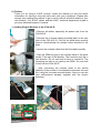
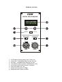
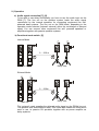
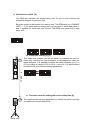
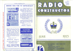
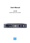
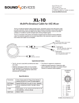
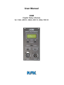
User Manual
DDM
Digital Delay Module
for CSA 400 D, QSA 200 D, QSA 500 D
0.) Preface
Thank you for using a K.M.E. product. Inside this manual you will find useful
information for having a long and safe work with your equipment. Please take
enough time reading this manual to get in touch with all technical details of your
new product. Your K.M.E. dealer and the K.M.E. technical department is glad to
give you additional support if needed.
1.) Adding Plug-In-Modules to the CSA 400 D
• Remove all cables, especially the power cord, from the
CSA 400 D.
• Remove the 4 screws holding the blind plate on the rear
side of the CSA 400 D. Pull out the blind plate carefully
without overstretching the multipin cable mounted to the
plate.
• remove the multipin cable from the blind plate carefully
• Take the DDM and plug in the multipin cable to the white
socket. Take care of the polarity. The connector only fits in
one direction. Do not use tools or force to connect it. The
remaining red wire is not used by the DDM. You can stuff
it back into the CSA 400 D.
• After connecting the multipin cable to the socket
carefully fit the module in the speakers extension slot and
fix it using the 4 screws removed earlier. Now you can use
your self-powered speaker together with the plug-in
extension.
Hardware overview
DDM
DIGITAL DELAY MODULE
DELAY
330.0 m
-
+
VALUE
CLEAR
DISPLAY
m / ms / ft
DELAY MODE
CALIBRATION
INT
OFF
EXT
ON
TONE SIGNAL
INPUT
OUTPUT
1 – LCD display showing delay time / delay unit
2 – minus key – decreases delay time by one unit
3 – plus key – increases delay time by one unit
4 – unit selector switch (meters / Milliseconds / feet)
5 – functional mode switch (internal / external)
6 – test tone switch (on / off)
7 – balanced audio input on DDM
8 – balanced audio output on DDM
2.) Operation
a) Audio signal connection [7], [8]
To be able to use delay functionality you have to use the audio input on the
DDM [7]. The line out on the speaker system leads the audio signal
reproduced by the internal speakers for connecting equipment like selfpowered bass systems. The line out on the DDM leads, depending to the
operation mode selected (internal/ external) either the un-delayed or delayed
signal. You can connect other equipment like self- powered speakers or
amplifiers together with passive speaker systems.
b) Functional mode switch [5]
Internal Mode
PLUG
IN
PLUG
IN
0 ... 330 m
Delay Line
Main PA
External Mode
PLUG
IN
PLUG
IN
0 ... 330m
Main PA
Delay Line
The ‘external’ mode supplies the delayed audio signal on the DDMs line-out.
The speaker itself works without delay. This mode was created for users which
want to use i.e. passive PA speakers together with an power ampIifier as
delay systems.
c) Unit selector switch [4]
The DDM will calculate the correct delay time for you by just entering the
acoustical distance in meters or feet.
Bring the switch to the position you want to use. The DDM asks you ‘CHANGE
UNIT?’ – if you really want to change the unit you have to press both keys (+
and -) together for more than one second. The DDM now works with a new
delay unit.
CHANGE
UNIT?
DELAY
X m
DELAY
X ms
DELAY
X ft
d) Delay time setting [2], [3]
PLUG
IN
The delay time needed can be set easily by pressing the plus or
minus key. Holding the keys increases or decreases the value by
larger amounts. It is possible to adjust the delay distance by 0,1 m
(10 cm) within an range of 330 m (or by 1 ms or by 1 ft) which should
be ideal for all sound reinforcement applications.
0 ... 330 m
Main PA
DELAY
0.0 m
DELAY
330.0 m
e) Test tone mode for setting the correct delay time [6]
The implemented test-tone generator is a useful tool which can help
you setting the correct delay time.
Delay Line
Example:
Main PA system could be a K.M.E. CA 6, both top units CSA 400 D are equipped
with DDM modules. Both modules are switched to ‘external’ operation mode
In the delay speaker positions work two additional K.M.E. CSA 400 D
You will need the following cable connections:
• 1 balanced audio line (XLR) running from Line-Out [8] on the DDM
to the Line-In of the CSA 400 D at the delay position
• mains power line to the CSA 400 D at the delay position
1.)
2.)
3.)
4.)
5.)
6.)
Set the unit on the DDM to ‘meters’ [4]
Set the DDM to „EXTERNAL“ operation mode [5]
Set the estimated delay distance [3], [2]
Turn DOWN the volume of BOTH CSA 400 D
Activate the test tone function [6]
Turn up the volume on the main PA until the test tone is audible at the position
of the delay speaker. Turn up the volume on the delay speaker until you hear
the signal in the same sound pressure level than the signal from the main PA
7.) Fine-adjustment of the delay time (distance) using + / - keys [3], [2], until only
one sound pulse (without “echo”) is audible – ready.
8.) Turn off test tone [6] and turn up the volume of both systems as necessary.
9.)
Klingenthaler Musikelektronik GmbH
Auerbacher Straße 268
08248 Klingenthal / Germany
phone +49 (0)37467 - 558-0
fax +49 (0)37467 - 558-33
www.kme-sound.com
[email protected]
Technical State February 2005.
The content corresponds to the state at printing. Subject to technical alterations. Misprints and errors expected.
Feb 2005 / SL