1
NAVAL POSTGRADUATE SCHOOL
Monterey, California
THESIS
AUTOMATED ASSESSMENT OF SQUADRON ENLISTED
MANPOWER, TRAINING AND READINESS
by
Daniel P. Granados
Kreg L. Kelly
September 2002
Thesis Advisor:
Co-Advisor:
John S. Osmundson
Dale M. Courtney
Approved for public release; distribution is unlimited
THIS PAGE INTENTIONALLY LEFT BLANK
REPORT DOCUMENTATION PAGE
Form Approved OMB No. 0704-0188
Public reporting burden for this collection of information is estimated to average 1 hour per response, including
the time for reviewing instruction, searching existing data sources, gathering and maintaining the data needed, and
completing and reviewing the collection of information. Send comments regarding this burden estimate or any
other aspect of this collection of information, including suggestions for reducing this burden, to Washington
headquarters Services, Directorate for Information Operations and Reports, 1215 Jefferson Davis Highway, Suite
1204, Arlington, VA 22202-4302, and to the Office of Management and Budget, Paperwork Reduction Project
(0704-0188) Washington DC 20503.
1. AGENCY USE ONLY (Leave blank)
2. REPORT DATE
3. REPORT TYPE AND DATES COVERED
September 2002
Master’s Thesis
4. TITLE AND SUBTITLE: Title (Mix case letters)
5. FUNDING NUMBERS
Automated Assessment of Squadron Enlisted Manpower, Training and Readiness
6. AUTHOR(S) Daniel P. Granados
Kreg L. Kelly
7. PERFORMING ORGANIZATION NAME(S) AND ADDRESS(ES)
8. PERFORMING
Naval Postgraduate School
ORGANIZATION REPORT
Monterey, CA 93943-5000
NUMBER
9. SPONSORING /MONITORING AGENCY NAME(S) AND ADDRESS(ES)
10. SPONSORING/MONITORING
N/A
AGENCY REPORT NUMBER
11. SUPPLEMENTARY NOTES The views expressed in this thesis are those of the author and do not reflect the official
policy or position of the Department of Defense or the U.S. Government.
12a. DISTRIBUTION / AVAILABILITY STATEMENT
12b. DISTRIBUTION CODE
Approved for public release; distribution is unlimited
13. ABSTRACT (maximum 200 words)
Manpower management within all activities of the United States Navy has traditionally been an extremely challenging
function. Careful, crucial reconciliation of manpower reports such as the Enlisted Distribution and Verification Report
(EDVR) and the Activity Manning Document (AMD) are a critical event in the proper execution of such a process.
Unfortunately, an automated process where such a manual, regularly occurring, time consuming, error prone, man-hour
intensive routine is performed does not currently exist. Specifically, in the area of Capability Ratings, Manning, Training,
Equipment and Supplies, an activity should be able to extract a prescribed range of data from their EDVR and AMD and have
it automatically calculate the T-Rating and M-Rating as required by the Functional/Type Wing Commander. This thesis will
attempt to address the feasibility, and requirements for such an automated software application utilizing COTS technology with
the additional utilization of application interface development to automate to the greatest degree possible, the regularly
recurring reconciliation of the EDVR and Activity Manning Document.
14. SUBJECT TERMS Manpower Database, AMO Database, Squadron EDVR, Squadron AMD,
Automated Manpower Assessment, Squadron Manning, Information Management Systems,
Client/Server Systems, Information Systems, Database Management Systems, Database, Decision
Support, Distributed Computing, NMCI, .NET, Web Enablement, Military Readiness
17. SECURITY
CLASSIFICATION OF
REPORT
Unclassified
18. SECURITY
CLASSIFICATION OF THIS
PAGE
Unclassified
NSN 7540-01-280-5500
15. NUMBER OF
PAGES
167
16. PRICE CODE
19. SECURITY
20. LIMITATION
CLASSIFICATION OF
OF ABSTRACT
ABSTRACT
Unclassified
UL
Standard Form 298 (Rev. 2-89)
Prescribed by ANSI Std. 239-18
i
THIS PAGE INTENTIONALLY LEFT BLANK
ii
Approved for public release; distribution is unlimited
AUTOMATED ASSESSMENT OF SQUADRON ENLISTED MANPOWER,
TRAINING AND READINESS
Daniel P. Granados
Lieutenant Commander, United States Navy
B.A., San Diego State University, 1989
Kreg L. Kelly
Lieutenant, United States Navy
B.S., United States Naval Academy, 1995
Submitted in partial fulfillment of the
requirements for the degree of
MASTER OF SCIENCE IN INFORMATION SYSTEMS TECHNOLOGY
from the
NAVAL POSTGRADUATE SCHOOL
September 2002
Author:
Daniel P. Granados
Kreg L. Kelly
Approved by:
John S. Osmundson, Thesis Advisor
Dale M. Courtney, Co-Advisor
Dan Boger, Chairman, Graduate School of Computer Sciences and
Information Systems
iii
THIS PAGE INTENTIONALLY LEFT BLANK
iv
ABSTRACT
Manpower management within all activities of the United States Navy has
traditionally been an extremely challenging function. Careful, crucial reconciliation of
manpower reports such as the Enlisted Distribution and Verification Report (EDVR) and
the Activity Manning Document (AMD) are a critical event in the proper execution of
such a process. Unfortunately, an automated process where such a manual, regularly
occurring, time consuming, error prone, man-hour intensive routine is performed does not
currently exist.
Specifically, in the area of Capability Ratings, Manning, Training,
Equipment and Supplies, an activity should be able to extract a prescribed range of data
from their EDVR and AMD and have it automatically calculate the T-Rating and MRating as required by the Functional/Type Wing Commander. This thesis will attempt to
address the feasibility and requirements for such an automated software application
utilizing COTS technology with the additional utilization of application interface
development to automate to the greatest degree possible, the regularly recurring
reconciliation of the EDVR and Activity Manning Document.
v
THIS PAGE INTENTIONALLY LEFT BLANK
vi
TABLE OF CONTENTS
I.
INTRODUCTION........................................................................................................1
A.
BACKGROUND ..............................................................................................1
B.
OBJECTIVES ..................................................................................................3
C.
SCOPE AND METHODOLOGY ..................................................................4
1.
Scope......................................................................................................4
2.
Methodology .........................................................................................4
D.
ORGANIZATION OF STUDY ......................................................................5
II.
LITERATURE REVIEW AND REQUIREMENTS DEFINITION.......................7
A.
EDVR USERS’ MANUAL ..............................................................................7
B.
COMPUTERIZED SELF EVALUATION CHECKLIST (CSEC) ............8
C.
OPNAVINST 1000.16J (MANPOWER MANUAL)...................................10
D.
TOTAL FORCE MANPOWER MANAGEMENT SYSTEM
(TFMMS) ........................................................................................................12
E.
DISCUSSIONS
WITH
CSFWP
(MAINTENANCE
AND
READINESS) .................................................................................................13
F.
SURVEY FOR REQUIREMENTS AND FINDINGS................................16
G.
SUMMARY ....................................................................................................20
III.
RESEARCH METHOD ............................................................................................23
A.
MODELING
UTILIZING
THE
UNIFIED
MODELING
LANGUAGE (UML) .....................................................................................23
1.
Plan and Elaborate Phase .................................................................23
a.
Critical Stakeholders...............................................................24
b.
System Boundary.....................................................................24
c.
System Functions ....................................................................25
d.
High Level Use Cases .............................................................27
e.
Use Case Diagram...................................................................29
f.
Expanded Use Cases ...............................................................29
g.
Ranked Use Cases ...................................................................31
h.
T-Rating Update Expanded Use Case ....................................32
i.
Conceptual Model and Decomposition ..................................33
2.
Analyze Phase.....................................................................................35
a.
Initial Concept Model .............................................................35
b.
Associations.............................................................................36
c.
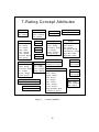
Discussion of Conceptual Model Attributes...........................39
d.
System Sequence Diagrams ....................................................42
e.
Contracts..................................................................................45
3.
Design Phase .......................................................................................49
a.
Real Use Case Description......................................................49
b.
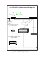
Collaboration Diagrams .........................................................51
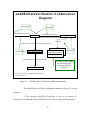
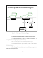
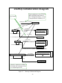
c.
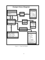
Design Class Diagram ............................................................62
4.
Summary.............................................................................................64
vii
IV.
MICROSOFT® .NET FRAMEWORK, VISUAL BASIC.NET AND
ADO.NET IMPLEMENTATION ............................................................................65
A.
INTRODUCTION..........................................................................................65
B.
ADO.NET ARCHITECTURE......................................................................66
C.
ADO.NET COMPONENTS..........................................................................67
1.
DATA PERSISTED AS XML ..........................................................70
2.
SCHEMA DEFINED DATA STRUCTURES.................................71
3.
DATA CACHING IN DATASETS ..................................................72
D.
PROMETHEUS CORE FUNCTION WALKTHROUGH........................73
1.
Import of the AMD and EDVR Text Files.......................................73
2.
Assisted Assignment of the BSC to the Sailor Record....................75
a.
Single Sailor Record Assignment ...........................................76
b.
Multiple Sailor Record Assignment .......................................77
3.
NEC Data, M-Rating and T-Rating .................................................77
4.
M-RATING COMPUTATION.........................................................78
5.
T-RATING COMPUTATION..........................................................79
E.
SUMMARY ....................................................................................................79
V.
CONCLUSIONS AND RECOMMENDATIONS...................................................81
A.
CONCLUSIONS ............................................................................................81
B.
RECOMMENDATIONS...............................................................................83
1.
Follow On Thesis Projects To Include:............................................83
a.
Multiple Thesis Submissions ..................................................83
b.
Adaptation of NEC Award Date Report .................................83
2.
Changes to Existing Manpower Database Systems ........................84
C.
FUTURE ENHANCEMENTS......................................................................84
1.
XML-based Web Service Application..............................................84
2.
NMCI ..................................................................................................84
3.
Security ...............................................................................................85
4.
Additional Subform Interfaces and Print Functions......................86
D.
PROTOTYPE DEMONSTRATION ...........................................................86
E.
SUMMARY ....................................................................................................87
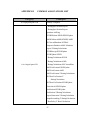
APPENDIX A
MAPMIS DECISION LOGIC TABLE ...........................................89
APPENDIX B
COMMON ASSOCIATIONS LIST.................................................97
APPENDIX C
CONCEPT ASSOCIATION DIAGRAMS....................................105
APPENDIX D
CONCEPT MODEL ATTRIBUTE DISCUSSION......................119
APPENDIX E
USERS’ MANUAL ..........................................................................123
APPENDIX F
DOWNLOAD THE APPLICATION.............................................143
GLOSSARY..........................................................................................................................145
BIBLIOGRAPHY ................................................................................................................148
INITIAL DISTRIBUTION LIST .......................................................................................149
viii
LIST OF ACRONYMS
ADO
AMD
AMO
API
BA
BNEC
BSC
CASE
COB
COM
COTS
CSFWP
CSEC
CTX
CWO
DAO
DB
DBMS
DCOM
DNEC
EAOS
EDA/L
EDVR
EDVRMAN
EPMAC
GUI
IEEE
IT-21
JTFX
LAN
LDO
MO
MSDN
NAMP
NAVMAC
NEC
NITRAS
NMCI
NTMPS
OLAP
OLE
OMG
ActiveX Data Object
Activity Manning Document
Assistant Maintenance Officer
Application Program Interface
Billets Assigned
Billeted Navy Enlisted Classification
Billet Sequence Code
Computer Aided Software Engineering
Current On Board
Component Object Model
Commercial –Off-The-Shelf
Command Strike Fighter Wing Pacific
Computerized Self Evaluation Checklist
Compulsory Training Underway Exercise
Chief Warrant Officer
Data Access Object
Database
Database Management System
Distributed Component Object Model
Distributed Navy Enlisted Classification
End of Active Obligated Service
Estimated Date of Arrival/Loss
Enlisted Distribution and Verification Report
Enlisted Distribution and Verification Report Manual
Enlisted Placement Management Center
Graphical User Interface
International
Information Technology for the 21st Century
Joint Training Forces Exercise
Local Area Network
Limited Duty Officer
Maintenance Officer
Microsoft Software Developers Network
Naval Aviation Manpower Program
Naval Manpower Analysis Center
Navy Enlisted Classification
Navy Integrated Training Resources and Administration System
Navy-Marine Corps Internet
Navy Training Management and Planning System
On Line Analytical Processing
Object Linking and Embedding
Object Management Group
ix
OOA&D
PC-EDVR
POB
POE
PNEC
PRD
RDBMS
RDO
ROC
SOAP
SORTS
SQL
SQMD
TFMMS
TSTA
UI
UIC
UML
VB.NET
W3C
XML
XSD
Object Oriented Analysis & Design
Personal Computer-Enlisted Distribution and Verification Report
Planned On Board
Projected Operational Environment
Primary Navy Enlisted Code
Planned Rotation Date
Relational Database Management System
Remote-access Data Objects
Required Operational Capability
Simple Object Access Protocol
Status of Readiness and Training System
Standard Query Language
Squadron Manpower Document
Total Forces Manpower Management System
Tailored Ships Training Availability
User Interface
Unit Identification Code
Unified Modeling Language
Visual Basic.NET
World Wide Web Consortium
Extensible Mark up Language
XML Schema Definition
x
LIST OF FIGURES
Figure 1.
Figure 2.
Figure 3.
Figure 4.
Figure 5.
Figure 6.
Figure 7.
Figure 8.
Figure 9.
Figure 10.
Figure 11.
Figure 12.
Figure 13.
Figure 14.
Figure 15.
Figure 16.
Figure 17.
Figure 18.
Figure 19.
Figure 20.
Figure 21.
Figure 22.
Figure 23.
Figure 24.
Figure 25.
Figure 26.
Figure 27.
Figure 28.
Figure 29.
Figure 30.
Figure 31.
Figure 32.
Figure 33.
Activity T-Rating Input Report........................................................................14
Monthly Activity T-Rating ..............................................................................15
Use Case Diagram............................................................................................29
Concept Model and Associations.....................................................................38
Concept Attributes ...........................................................................................40
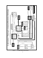
Conceptual Model with Attributes...................................................................41
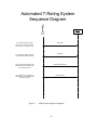
AMO System Sequence Diagram ....................................................................43
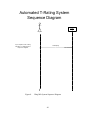
Wing MO System Sequence Diagram .............................................................44
System Operations ...........................................................................................45
Add AMD Collaboration Diagram ..................................................................52
Add EDVR Collaboration Diagram.................................................................54
Add NEC Date Verification Collaboration Diagram.......................................56
End Calculation Collaboration Diagram..........................................................58
Make Output Collaboration Diagram ..............................................................59
Start-up Collaboration Diagram.......................................................................61
Design Class Diagram......................................................................................63
ADO.NET architecture and components .........................................................67
OLE DB Architecture ......................................................................................67
ADO – OLE DB Object Interface....................................................................68
ADO.NET Components...................................................................................69
ADO.NET DataSet ..........................................................................................71
Import Wizard Welcome Screen......................................................................74
BSC Assignment Form ....................................................................................76
BSC Assignment Data Grid .............................................................................77
NEC/Rating View/Print Form..........................................................................78
PMMS Main Window....................................................................................131
Import Wizard................................................................................................132
BSC Form ......................................................................................................132
Personal & Professional Data ........................................................................133
NEC Data View .............................................................................................133
Form Navigation Buttons...............................................................................137
Paygrade Drop Down List .............................................................................138
Paygrade Drop Down List open.....................................................................138
xi
THIS PAGE INTENTIONALLY LEFT BLANK
xii
LIST OF TABLES
Table 1.
Table 2.
Table 3.
Table 4.
Table 5.
System Functions .............................................................................................27
Ranked Use Cases............................................................................................32
Concept Category List .....................................................................................35
Conceptual Objects (from Larman, p. 103) .....................................................37
Contract Schema ..............................................................................................45
xiii
THIS PAGE INTENTIONALLY LEFT BLANK
xiv
ACKNOWLEDGMENTS
We would like to thank our advisors, Professors John Osmundson and Dale
Courtney for their guidance, inspiration and teaching. They both greatly helped to
provide the spark and fuel for the fire in our journey through this study.
We also would like to thank LT Dwayne Cole for his assistance early on for
demonstrating that a multi-functional manpower management database is possible – he is
a true pioneer in this respect.
Lastly, we would also like to thank CDR Tim Holland who, without his creativity
intelligence, and visionary outlook, this thesis would not have begun.
xv
THIS PAGE INTENTIONALLY LEFT BLANK
xvi
I.
A.
INTRODUCTION
BACKGROUND
In aviation squadrons throughout the Navy, the maintenance department makes up
a predominant percentage of the command as a whole. Within this department are
numerous highly trained technicians who play a critical role in the operational readiness
and availability of the aircraft and systems for which they are responsible. It is for this
very reason that the management of their training, career development and assignment is
so vitally important within aviation squadrons.
Ensuring that the right people are
assigned to fill the right billets so a proper mix of experienced and not so experienced
technicians always exists is the management goal. Knowing how to achieve this proper
balance of maintenance expertise in a world where tours of duty force people to transfer
every two to four years, and the attractiveness of civilian employment lures experienced
technicians to leave the Navy, is one of the biggest challenges that face manpower
managers overall.
Like any organization that deals with human resources, in order to address the
challenges of managing personnel, training, and readiness in aviation squadrons, the
functions and responsibilities of a manpower manager were developed and assigned to
one officer in the command. Today, the Assistant Maintenance Officer (AMO) in a
typical squadron executes this function. The AMO is normally an aviation ground officer
who is an Aerospace Maintenance Duty Officer (AMDO), Limited Duty Officer (LDO),
or Chief Warrant Officer (CWO). For most, their only exposure to any sort of manpower
management education or training occurs during aviation ground officer school, or AMO
School at Naval Air Station Pensacola, Florida.
There, reference materials and
responsibilities are reviewed and the process of manpower management within the Navy
is discussed. As with any education or training, however, real insight and understanding
does not immediately occur. It is only after some amount of on-the-job training and
working in the fleet does one become experienced to the point that learning is reinforced.
For most Assistant Maintenance Officers, it is said that the manpower management
function can be the most complex yet critical aspects of the job. Is it not a wonder that in
1
this day and age of the Information Revolution why manpower management remains as
time consuming and complex as it does?
Assistant Maintenance Officers currently use paper copies of reports such as the
Enlisted Distribution and Verification Report (EDVR) and the Squadron Manning
Document (SQMD) or Activity Manning Document (AMD) to reconcile manning issues
and manage their manpower databases. Both reports are published regularly. The EDVR
is published monthly while the SQMD/AMD is published upon completion of an activity
Aviation Manpower Requirements Determination (for SQMD’s) or Shore Manpower
Requirements Determination (for AMD’s), or as major changes occur.
Technology has changed over the years and today now allows users to both view
and download these documents via electronic means. Unfortunately, that is the limit to
what the manpower manager at the squadron level can do. There exists no application to
process data from different databases.
More so, the databases from which these
documents are generated are proprietary systems that require cooperation/authorization
from the highest levels of Functional/Type Commanders to update or make changes to.
This thesis is a study of an application to address aspects of manpower
management functions by automating the reconciliation process between the EDVR and
the SQMD/AMD—matching the bodies assigned to the billets assigned within a
squadron.
The solution capitalizes on the use of existing commercial-off-the-shelf
(COTS) technologies, existing manpower databases maintained within the Navy, and
automating a process that is normally done on paper with pen mark-ups. This solution
merely addresses a portion of the overall responsibilities of the manpower manager. A
prototype application is also described in this thesis that provides the necessary
functionality of such an application. Critical issues and communication channels are
discussed and areas requiring future research are noted.
The future growth of web-based capabilities provided by the Navy-Marine Corps
Intranet (NMCI) and the Navy’s Information Technology for the 21st Century (IT-21)
infrastructure may prove to be a logical path for manpower management to become
increasingly easy to use on a more real time basis resulting in more accurate manpower
2
management and reporting. Although the application presented in this thesis does not
include an internet interface and is only prototype in nature, we foresee that an enterprisescale development similar to that discussed here is inevitable— incorporating database
and web-enabled tools, which presumably use the Internet as a logical communication
medium to share data across activities, echelon commands and any distances imaginable.
The biggest challenges manpower managers of today face are education of users and
managers, and acquiring modern tools and technology to meet increasing demands of
working more efficiently and intelligently. The usefulness of a relational manpower
management database will depend on whether the system adds value to the underlying
activity manning data, and ultimately, whether the end user gains knowledge of the
overall readiness of their activity’s command and personnel.
B.
OBJECTIVES
Today, manpower management is a manual process. If not done correctly, one
may rapidly become a spectator to the very process, gone awry, that is supposed to be so
closely managed. What this thesis intends to provide is one way to greatly reduce the
transaction costs and manual aspect of what may be viewed as a database management
problem with respect to “bodies and billets.” In our experience and understanding of
manpower management, we asked the following: Would it be possible to develop an
application that could automatically read and import data from an activity’s EDVR and
compare it with the standing SQMD/AMD at various milestone points of a
deployment/turnaround cycle to produce a report of overall T-Ratings (a rating based on
an individual’s training level and years of experience in current Navy Enlisted
Classification (NEC) Code) and M-Ratings (a simple Current On Board (COB) per
Billets Assigned (BA)) for individuals within the command? If so, can the M-rating for
each Type/Model/Series and/or system be computed and evaluated automatically? Could
a secure, internet-based application be developed for the user to interface with a central
database? Is it not only possible, but also practical to use a central, unified database for
data input/output, storage, processing, and archiving of data to meet manpower
3
management requirements so that the manager can make the best decisions afforded him
at any given time?
Our objective in this study has boiled down to providing the manpower manager
with a more automated method to reconcile the EDVR and SQMD/AMD so that the
AMO can focus more on “management” and less on “processing” – something a
computer functions better at.
C.
SCOPE AND METHODOLOGY
1.
Scope
This thesis will encompass a study of existing naval manpower COTS
applications such as Enlisted Placement Management Center’s (EPMAC) PC-EDVR, the
WildCat Navigator for EPMAC telnet, Total Force Manpower Management System
(TFMMS), the Navy Training and Management Planning System (NTMPS), and the
Citrix Client for NTMPS database server access and other application interface
technologies. Microsoft Access is used in this thesis as the primary database. Although
databases that are more powerful exist, for the purpose of a database within a single
department, Microsoft Access was found to soundly meet these needs. It is also part of
the Navy’s IT-21 office suite standard as well.
This thesis will discuss areas of
deployment and reveal its benefits to manpower managers as well as the shortcomings of
the current process. Furthermore, it will suggest possible areas of additional applicability
beyond the initial implementation environment. The ultimate goal of this thesis is to
deliver a useable application and documentation that greatly increases efficiency and
effectiveness of the manpower manager, enables greater manpower knowledge, and
simplifies the reports processing functions.
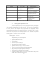
2.
Methodology
The methods used in this thesis research will consist of the following steps:
1. Conduct a literature search of directives, instruction, manuals, requirements,
books, and other library information.
2. Interview current users (Squadron AMO’s) who perform the manpower
management functions.
4
3. Initiate and issue a user questionnaire to query for user desires, requirements,
and areas for strategic improvement in the current manpower management
process.
4. Conduct a thorough review of current manpower procedures, processes, and
policies.
5. Develop use cases.
6. Explore and contrast the various alternatives applicable.
7. Determine how existing capabilities provide managers with the tools and
information to make decisions based on current system inputs and outputs.
8. Gather data points via questionnaires on shortfalls and strengths of the
existing system as well as what the ideal automated system might be.
9. Review current prototypes and utilize CASE tools for requirements analysis.
10. Utilize Object Oriented Analysis/Design and the Unified Modeling Language
(UML) to assist in the determination of proper requirements and design of the
thesis.
11. Determine and utilize the proper productivity metrics in order to determine
existing performance levels compared to changes resulting from this thesis.
D.
ORGANIZATION OF STUDY
This chapter provides a background to the importance of manpower management
and introduces the research covered in this thesis. In Chapter II, a review of policies and
regulations is presented in order to clearly illustrate requirements set upon the manpower
manager and to educate the reader to such.
Chapter III focuses on the research methods used.
In establishing user and
application requirements we met with Commander Tim Holland, Command Strike
Fighter Wing Pacific (Maintenance and Readiness) acting and Lieutenant Dwayne Cole,
Assistant Maintenance Officer, VFA-125. A survey was also provided to all squadron
AMO’s of CSFWP for input as well via the NPS SPEAR website.
5
The name of this prototype application is Prometheus, named so after the
mythical Greek god who taught humans various arts and endowed them with the spark of
life from the flame of Zeus. In its development, the Unified Modeling Language (UML)
was utilized in requirements analysis and application design. In Chapter III we discuss
our reasoning, process, and results, which are demonstrated in Prometheus.
Chapter IV describes implementation issues such as compatibility, requirements,
technical support and back-up issues.
Chapter V addresses operating procedures such as training, maintenance, and
documentation.
Chapter VI presents the conclusion by readdressing questions initially presented
in this research. Recommendations are also made to provide all parties interested with a
potential solution to improving manpower management Navy wide.
6
II.
LITERATURE REVIEW AND REQUIREMENTS DEFINITION
In this thesis, as with any other project, in order to more fully understand the
problem being addressed, an attempt to first thoroughly understand that problem must
take place.
Prior to taking any action, one has to observe, analyze, and make an
intelligent choice as to which direction to head off, otherwise a great deal of time, energy
and effort might all be expended for no good reason. The development cycle will then
need to start again from scratch in another attempt to “get it right”. To prevent this
wasted effort, we have decided to begin with a review of currently established
instructions and directives with respect to manpower management in the Navy.
A.
EDVR USERS’ MANUAL
The Enlisted Distribution and Verification Report Manual (EDVRMAN) is a
document published by the Enlisted Placement Management Center (EPMAC), New
Orleans, Louisiana.
The EDVRMAN publishes format and procedures for EDVR
validation and review. As stated on the cover page of the document:
The Enlisted Distribution and Verification Report Users’ Manual
(EDVRMAN) is the official manual for interpreting and validating the
Enlisted Distribution and Verification Report.
The EDVRMAN
supplements basic regulation and requirements published in references (a)
through (c).
Nothing in the EDVRMAN shall be construed as
contravening or superseding other directives issued by the Navy
Department.
The EDVRMAN is a document that provides an in-depth explanation of all 12
sections of the EDVR.
Within the manual, there are numerous references to
“verification” and “validation” of data that are contained in the EDVR itself. “Required
and recommended actions” are explained as well. For example, in Section 2, paragraph
2.2.3, it discusses the verification of the Distribution Navy Enlisted Classification (NEC)
Code.
Although “the [EDVR] system has a built-in DNEC to NEC inventory
discrepancy flag process”, the activity will still need to verify the NEC’s of the
7
prospective gain when alerted by the EDVR system. (EDVRMAN, section 2.2.3)
Throughout the manual, “Required and Recommended Actions” for specific situations
are also explained. More specifically, in Section 8, paragraph 8.5 of the EDVRMAN, the
crux of manpower management tasking is stated:
a. Upon receipt of the monthly EDVR, the activity will verify actual NEC
qualifications and the validity of the assigned DNEC of the enlisted
personnel on board in relation to:
(1) The NEC authorized in the Activity Manpower
Document (AMD), and its latest revision as contained in EDVR Section 6.
(2) The individual’s actual qualification against the
member’s field service record and EDVR sections 4 and 8.
b. If the NEC or its principal is not held in the inventory, three asterisks
and a numerical code (See Section 2, paragraph 2.2.3b for explanation of
these codes) will appear in the INEC columns indicating that local
verification of the member’s qualification in accordance with Volume II of
the Manual of Navy Enlisted Classification Standards (NEC Manual)
NAVPERS 18068F is necessary and the command is required to take the
following actions to correct the discrepancy…
Lastly, in Section 15 of the EDVRMAN, a decision logic table listing events,
actions, references, and remarks can be found which greatly helps to guide the EDVR
reviewer in the necessary direction to resolve questions or concerns. An extract of this
table is located in Appendix A of this thesis. The EDVRMAN is an important document
because “manning and assignment decisions are based on information contained in the
EDVR. It is extremely important that each activity keep its account up-to-date and
accurate by reporting personnel events as they occur and correcting errors when
identified.” (EDVRMAN, section 1.4)
B.
COMPUTERIZED SELF EVALUATION CHECKLIST (CSEC)
The Computerized Self Evaluation Checklist (CSEC) is a document published by
Naval Air Systems Command (AIR 3.2D), as a tool for ensuring that aviation commands
are managing all programs required of the Naval Aviation Maintenance Program
(NAMP), OPNAVINST 4790.2 in a standardized manner.
8
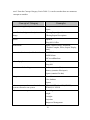
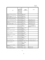
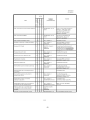
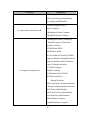
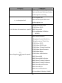
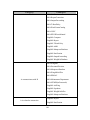
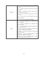
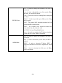
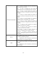
There are 26 programs
dictated in the NAMP, of which Manpower Management is one. In the CSEC, there is an
area checklist for Manpower Management. The following questions, 14 in all, taken
from the checklist have also been considered requirements for this thesis since it is from
this checklist that the Type Commander Aviation Maintenance Management Team
(AMMT) will evaluate a squadron.
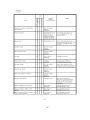
NUMBER
QUESTION
2801C
Is the Manual of Navy Total Force Manpower Policies and Procedures
(OPNAVINST 1000.16J) utilized by all echelons in dealing with
manpower change requests or other manning issues? Ref. OPNAVINST
4790.2H, vol. I, par. 2.4e
2802C
Is the AMD reviewed biennially (every two years) by the Manpower
Manager?
Refs. OPNAVINST 4790.2H, vol. I, par. 2.4e and
OPVANINST 1000.16J, par. 8.15.a
2803C
Is each publishing of the EDVR reviewed for accurate and up to date
information?
Refs. OPNAVINST 4790.2H, vol. V, par. 2.3e(12);
EDVRMAN, par. 1.4; and NAVPERS 15909F, par. I.032
2804C
Are AMD (Activity Manning Documents) change requests submitted
whenever changes are requested? Refs. OPNAVINST 4790.2H, vol. I, par.
2.4c and OPNAVINST 1000.16J, par. 1003.1
2805C
Are DNEC Change Requests submitted to EPMAC for personnel whose
DNECs are incorrect or for personnel who obtain NECs currently listed on
Manpower Authorization, but are unfilled? Refs. OPNAVINST 4790.2H,
vol. I, par. 2.4e and EDVRMAN, secs. 8.3.2e, 8.5.1d and 8.5.2
2806C
Are appropriate personnel documents (EDVR, AMD and standard transfer
directives) monitored to ensure personnel assigned already possess the
requisite skills, or will receive training prior to arrival, commensurate with
the billet/DNEC? Ref. OPNAVINST 4790.2H, vol. V, par. 2.3e(12)
2807C
Are maintenance personnel working in the billets assigned (DNEC) on the
EDVR? Refs. OPNAVINST 4790.2H, vol. I, par. 2.4e and EDVRMAN,
par. 8.5.2
2809C
When critical manning shortages (including NECs) are identified, is an
Enlisted Manning Inquiry Report (EMIR) submitted to EPMAC? Ref.
OPNAVINST 4790.2H, vol. I, par. 11.2.2b(6) and NAVPERS 15909F
(ENLTRANSMAN), ch. 26.02
2810C
Are messages forwarded to EPMAC requesting PRD adjustments on
personnel that are separated prior to their PRD? Ref. OPNAVINST
4790.2H, vol. I, par. 11.2.2b(6) and NAVPERS 15909F, par. 3.063
9
2811C
Does the AMO determine the apportionment of maintenance personnel to
the department and monitor/coordinate the assignment of TAD personnel?
Ref. OPNAVINST 4790.2H, vol. I, par 11.2.2b(7)
2813C
Are NEC discrepancies in the command’s Activity Manpower Document
corrected? Refs. OPNAVINST 4790.2H, vol. I, par. 2.4; EDVRMAN, sec.
8.5.1d; and OPNAVINST 1000.16J, par. 1003
2814C
Are discrepancies in an individual’s NEC qualification(s) (loss of required
qualification/certification/proficiency, etc.) corrected by submitting a
NACPERS 1221/1 or by completing the NEC Discrepancy Report? Ref.
OPNAVINST 4790.2H, vol. I, par. 11.2.2b(6) and EDVRMAN, sec. 8.5.1d
2815C
Does the activity maintain a current organizational roster board, automated
or manual, which includes as a minimum, name, rate and billet assignment
in conjunction with the AMD? Ref. OPNAVINST 4790.2H, vol. I, par.
11.4.b(12)
2816C
Are individual NEC qualifications validated against assigned DNECs?
Ref. OPNAVINST 4790.2H, vol. I, par. 11.2.2b(6) and EDVRMAN, sec
8.5
C.
OPNAVINST 1000.16J (MANPOWER MANUAL)
The Manual of Navy Total Force Manpower Policies and Procedures instruction,
OPNAVINST 1000.16J, is a document issued by the Office of the Chief of Naval
Operations.
This instruction is the governing document from which subordinate
commands delineate additional manpower requirements for their specific functions and
applications. The purpose of the document is to “provide policy guidance and procedures
to develop, review, approve, and implement total force manpower requirements and
authorizations for naval activities”. (OPNAVINST 1000.16J, secn. 1.a) It also assigns
management responsibilities and details manpower procedures for determining
manpower requirements and authorizations. This document also establishes manpower
requirements through several programs designed for all components of the Navy. The
program specifically used for squadron manpower requirements is the Aviation
Manpower Requirements Determination Program for Squadron Manpower Documents
(SQMD’s), carrier air wings (CVW’s), and afloat aircraft intermediate maintenance
departments (AIMD’s).
10
First, an understanding of manpower requirements should be taken from the
instruction. As stated in section 4.a (2):
Manpower requirements shall be based on directed mission, functions, and
tasks (MFT’s) and/or required operational capability/projected operational
environment (ROC/POE) and reflected on the Activity Manpower
Document (AMD). Workload shall be determined using industrial
engineering or other justifiable techniques that yield accurate manpower
requirements.
Also, as stated in section 200.5:
The ROC/POE is the most critical element in developing manpower
documents. The ROC provides a precise definition of the unit’s mission
statement. The POE is a description of the specific operating environment
in which the unit is expected to operate.
In section 4.a (3):
Manpower requirements shall reflect the minimum quantity and quality of
manpower required for peacetime and wartime to effectively and
efficiently accomplish the activity’s mission. Military quality information
includes designator/paygrade, rating/rate, subspecialty (SUBSP),
Additional Qualification Designation (AQD) and Navy Enlisted
Classification (NEC) codes.
Responsibility for the Aviation Manpower Requirements Determination Program
is assigned to Navy Manpower Analysis Center (NAVMAC) for the development and
documentation of total force manpower requirements for all fleet activities.
(OPNAVINST 1000.16J, secn. 4.b)
In section 5, manpower management is defined as “the methodical process of
determining, validating, and using manpower requirements and active duty MPN/RPN
manpower authorizations and end strength.”
Lastly, the Activity Manning Document is described and defined in Chapter 10 of
enclosure (1):
Manpower requirements are initially published in draft SMDs, FMDs,
SQMDs, and SEAOPDET manpower documents. Once the review cycle
11
is complete, CNO (N12) will direct changes accordingly and NAVMAC
will produce and upload a final SMD, FMD, SQMD, or SEOPDET
manpower document into TFMMS. Subsequently, an AMD will be
available from TFMMS and will serve as the single source for manpower
requirements and authorizations data. The AMD displays a complete
picture of total force manpower requirements as they change across the
Future Years Defense Plan. (OPNAVINST 1000.16J, Encl. (1), Ch. 2,
secn 200.2)
The SQMD that is processed and ultimately ends up as an AMD in TFMMS is the
direct input tool for a command to affect changes to its manpower. It is for this reason
that the squadron AMO must have a through understanding of command manning as well
as all information (e.g. NEC, experience level, PRD, EAOS, etc.) pertaining to the
members of the department. Additionally, changes to the SQMD may be required if there
are changes in the assigned aircraft, flight hour utilization rates, fleet replacement
squadron (FRS) student throughput, FRS curriculum, corrective maintenance model, and
major changes in mission, force structure, or fleet issues. (OPNAVINST 1000.16J, Encl.
(1), Ch. 2, secn. 202.3) Additionally, enclosure (1), section 203.2 lists SQMD manpower
document development elements.
D.
TOTAL FORCE MANPOWER MANAGEMENT SYSTEM (TFMMS)
The Total Force Manpower Management System (TFMMS) is the single
authoritative database for total force manpower requirements and active duty MPN/RPN
(Manpower and Personnel, Navy/Reserve Personnel, Navy) manpower authorizations and
end strength.
A manpower authorization cannot exist without a valid manpower
requirement documented in TFMMS.
TFMMS is an information system designed to support Deputy Chief of
Naval Operations (M&P) (N1) by providing a single, authoritative source
for manpower data. Located on a mainframe computer, this data includes
manpower requirements, which manpower requirements are authorized
(funded), and the resources used to authorize the requirement. TFMMS
allows the ability to track manpower for the active military (officer and
enlisted), reserve military, civilians, contractors, and other categories of
manpower (e.g., other military services). TFMMS provides access to
12
current data, and storage and retrieval of historical data for resource
sponsors, manpower claimants, SMC’s and other management information
users. Additional information and procedures can be found in [the Total
Force Manpower Management System (TFMMS) Users’ Manual].
(OPNAVINST 1000.16J, secn. 900.1)
In addition to the central database used for housing manpower data, an application
also exists for manpower users to interface with the database; however, access is limited
to manpower personnel at the SMC level and above - a classification level that the
squadron AMO is not granted. The TFMMS Micro Manpower Change Application
(TMMCA) is a:
…software package for [a] personal computer that allows manpower
managers to initiate AMD Change Requests, provide AMD and end
strength information, reports, and summaries. By using the TFMMS
mainframe computer, TMMCA can be used to download a specific
activity’s or the entire manpower claimant’s and/or SMC’s AMD and end
strength. The AMD and end strength can be copied and used on a PC for
other TMMCA users to create AMD Change Requests and/or query
reports. (OPNAVINST 1000.16J, secn. 901.1)
This application is not used at the squadron level, but is used at the Wing level.
Squadron AMO’s must coordinate with the Wing manpower manager for access/reports
utilizing TMMCA.
E.
DISCUSSIONS WITH CSFWP (MAINTENANCE AND READINESS)
The idea of this thesis first occurred in the Fall of 2001 when, in our search for a
database-related topic, we were given an opportunity to speak with the acting
Commander Strike Fighter Wing Pacific (CSFWP) Maintenance Officer, Commander
Tim Holland. Our first discussions with him were primarily via e-mail regarding the
development of an application to report the training level of a squadron, or T-Rating as it
is normally called, in a manner that would be easy to display, calculate, and brief to
others. Commander Holland, who had been working on a solution to this himself,
presented to us the idea that an activity utilize an application to import fields from their
13
EDVR/AMD, manually or automatically, enter the T-Rating for each individual at a
number of points (projecting for the future as well based on present data) then evaluate
the matrix to determine/calculate the overall T-Rating. Ideally it would evaluate values at
the following points in the deployment training cycle: 1) Now, 2) TSTA, 3) CTX, 4)
Fallon, 5) JTFX and 6) Deployment Day ONE. His comments became the essence of the
first objective of this thesis. This greatly contributed to making the definition of the
problem clear. In one e-mail from CDR Holland he stated:
A very sophisticated program would simply read the EDVR/AMD directly
and evaluate the M and T ratings. The idea is to identify early weak areas
and get training or bodies and training to fix the problem. The tool must
have the ability to do ‘what if’ scenarios and be simple to use by noncomputer folks. Most JO’s today can easily use Excel. Access is a bit
problematic but with proper menus and utilities would work. (Holland, email dated 11OCT01)
This became the first requirement, which we set out to analyze, and CSFWP
Maintenance became the primary customer. It was during this analysis period when we
concluded that the solution we sought was more likely a product of the squadron
Assistant Maintenance Officers’ manpower management process.
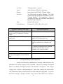
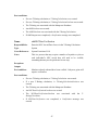
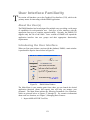
We began our definition phase by deciding to focus first on the T-Rating instead
of the M-Rating, as it was the more complex of the two. The CSFWP MO specifically
detailed what data fields were required as input in the calculations of the T-Rating.
Depicted in Figure 1 below is a sample report of the fields used.
Figure 1.
Activity T-Rating Input Report
14
Almost all the data contained in this report is pulled from other reports,
specifically from each squadron’s EDVR and SQMD. There is one area where the
AMO’s input and logic are involved though - the assignment of “area”. This is the area
in the squadron to which the member is assigned for duty within the department. This is
not data already published in any document, nor is it static. The AMO could change this
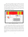
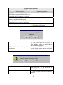
area assignment periodically. The data from this report is then used to compile an overall
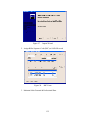
activity report as illustrated below in Figure 2.
Figure 2.
Monthly Activity T-Rating
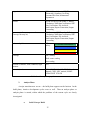
From the discussions with the CSFWP MO, we were able to more clearly define
the problem as a database situation where data from multiple databases needed to be
aggregated and reported first, so that a calculation could be performed resulting in a
rating that could be reported and displayed in a number of ways. The product of such an
automated process could also be a feeder to the monthly Status of Readiness and Training
System (SORTS) reports. We concluded that we would pursue an application that would
automatically assess the existing training and readiness of an activity based on its EDVR
and AMD.
15
F.
SURVEY FOR REQUIREMENTS AND FINDINGS
Within CSFWP, there are 17 squadrons.
Of these, many were not at NAS
Lemoore, CA during the times we were able to visit there. In our attempts to reach as
many AMO’s as possible, and in coordination with the Wing AMO, an invitation to
participate in an on-line survey was given to all wing AMO’s. The survey was titled
AMO
Manpower
Survey
and
was
located
at
the
following
URL:
http://www.nps.navy.mil/spear/surveys/amomanpower.htm. This survey was active from
June 2002 until August 2002. Following are questions (Q’s) that were used to poll
AMO’s for their input regarding requirements for an automated manpower application
and the responses (R’s) received:
Q1. What factors do you, the manpower manager, consider most important in
performing this aspect of your job.
R1. RIS runs and the SQMD (soon to be F/A-18F AMD once finalized)
R2. Walking the beat, contacting EPMAC and BUPERS. Trips to same. The
ARIS, and NTMPS (which you still can't get on NMCI).
R3. The ability to look at near-real time data on the number of incoming and
outgoing personnel in order to report accurately the readiness with regards to
manpower, training and NEC management
Q2. In what areas of manpower management do you feel you need help more
than others?
R1. The continuity between what EPMAC-BUPERS and NAVMAC are able to
see. I believe there should be "one-stop-shopping" when it comes to
manpower and the assessment of where you are as an activity.
R2. AMD’s and SQMD's need to be more precise. I don't need mission NEC's.
Give me the baby, not the labor pains.
R3. The ability to capture data from various sources.
Q3. In performing the manpower management functions of your job, how do you
assess the T-Rating for your department now?
16
R1. I take the number of billets with an NEC attached to it and plug the personnel
within the department into those billets and assess the shortages or overages
of each rate for the particular NEC.
R2. Don’t know
R3. Through the use of SORTS software from OPS
Q4. Do training issues, with respect to generating a T-Rating report, for your
department, exist? If so, which aspects are most challenging to you?
R1. no response
R2. Mainly for OP's.
R3. Collecting and disseminating the data.
Q5. How do you assess Manning levels for your department now?
R1. I take the POB-9 and divide it by the M+1 for each particular rate area and
derive a percentage. Then I perform the same math for the overall
maintenance department. As far as the SORTS for each mission area, OPS
provides the "T" of the T& R matrix and I provide manning numbers for the
SORTS report
R2. No response
R3. Through EDVR, ARIS
Q6. What format of the EDVR do you use?
R1. Paper copy
R2. Paper copy. ELECTRONIC COPY UNREADABLE (LIGHT GREY)
R3. Paper copy
Q7. How do you receive the monthly EDVR?
R1. Personnel Department copy of the downloaded document
R2. Downloaded from EPMAC
17
R3. Electronic file located on command LAN
Q8. In your opinion, what would be the ideal way to receive the EDVR?
R1. Electronically via the Web
R2. There should be a real-time, web-based EDVR which is easier to read than
the current PC-EDVR. Should have access to detailers' database, which
projects further out than EDVR.
R3. E-mail to admin, so they can e-mail me the sections I desire.
Q9. How do you receive the command Manning Document (SQMD/AMD)?
R1. Electronic file is e-mailed to you; WORD format, needs to be Excel
R2. CDFWP forwards electronic copy
R3. Squadron doesn't have one yet
Q10. In your opinion, what would be the ideal way of receiving the Manning
Document?
R1. Electronically in Excel format
R2. E-mailed automatically to commands as soon as available.
R3. Same as EDVR
Q11. Are you familiar with the T-Rating CDR Holland was developing while
acting as CSFWP Wing MO?
R1. no
R2. no
R3. no
Q12. If yes to above question, please elaborate some on what you thought its
Strengths and Weaknesses were.
R1-3. All responses N/A.
Q13. Would more directions/instructions be desirable for this type of application?
18
R1-3. All responses N/A.
Q14. At what time periods is data input to your Manning Database?
R1. Weekly
R2. Daily
R3. Monthly
Q15. At what time periods is the data output? (i.e. to reports, archive files, other
databases, etc.)
R1. Weekly
R2. Weekly
R3. As changes occur
Q16. At what time periods are reports written?
R1. Monthly
R2. Weekly
R3. As required
Q17.
How many transactions do you process per month in you Manpower
Database?
R1. 25
R2. 26-50
R3. 0-10
Q18. What should a manpower application be able to do for you in order to be
considered a functional program?
R1. Be input and sorted in Excel
R2. Needs to project future manning based upon current information. Needs to
present data in various forms, and be capable of generating outputs that can
be designed by the user.
19
R3. Don’t know
Q19. How much experience do you have with Microsoft Excel?
R1. Very much
R2. Very much
R3. Very little
Q20. How much experience do you have with Microsoft Access?
R1. Some
R2. Very much
R3. None
Q21. Please list references used/found useful regarding Manpower Management.
R1. NTMPS - SQMD - OPNAV 1000.16J - ROC/POE
R2. EDVRMAN
R3. Nothing that gives a brand new AMO a clue.
Q22. Please provide your contact information so that we may get back with you.
Survey Comments:
R3. EDVR needs to be replaced with a superior, real-time product.
G.
SUMMARY
Requirements definition can probably be stated as being the most critical step of
requirements analysis. Gaining a better understanding of what the issues are and how
they are structured into the customer’s business practices has been the goal of our
requirements analysis in this study. In this particular instance; however, there are not
only the users’ ideas of how the business practices occur, but there are also instructions
and directives that dictate specific actions and responsibilities. It is for this reason that
we have considered many of these documents, such as the Computerized Self Evaluation
20
Checklist, as additional requirements of what a system must satisfy, and why we have
reviewed them here in this chapter.
Chapter III will further expound on the results of this chapter, and then go further
into an analysis of the requirements for our development. From this, we start the design
and lastly development of the solution, which we are proposing in this thesis
21
THIS PAGE INTENTIONALLY LEFT BLANK.
22
III.
A.
RESEARCH METHOD
MODELING UTILIZING THE UNIFIED MODELING LANGUAGE
(UML)
1.
Plan and Elaborate Phase
For this study, an Object Oriented Analysis and Design (OOA&D) methodology
was used to identify system requirements. As opposed to a functional approach, an
Object Oriented approach is taken to analyze the results of the requirements definition.
To construct and present concepts and their relations, the Unified Modeling Language
(UML) was used. From the software development aspect, the UML best standardizes
representations and terminology as well as the steps of the development process. The
requirements analysis product within this chapter has been produced using methods
discussed in the textbook Applying UML And Patterns; An Introduction To Object
Oriented Analysis and Design, by Craig Larman. Many of the figures and diagrams have
been modeled in the Larman textbook style.
The ultimate goal of object oriented analysis and design utilizing the unified
modeling language is “finding and describing objects or concepts in the problem domain”
and “defining logical software objects that will ultimately be implemented in an object
oriented programming language” such as UML. (Larman, p. 6)
Within OOA&D, although no structured process is prescribed, we have defined
our development process as such: 1) Plan and Elaborate Phase, 2) Analyze Phase, 3)
Design Phase, and 4) Construct Phase. The development process may be considered
modular - steps do not necessarily have to be completed sequentially. In fact, at some
points it may be desirable to work concurrently on more than one step. The beauty of
OOA&D is that it is a methodology that is certified by the International Electrical and
Electronics Engineers (IEEE) and the Object Management Group (OMG), an industry
standards organization.
It is well recognized throughout the software development
industry and will be around for years to come.
In planning, we first identified the critical stakeholders. A critical stakeholder is
someone who owns a process or is a critical component of a process. They could also be
23
viewed as individuals, groups, or organizations that could make or break the project if
their needs are not met. A list of our initial critical stakeholders follows with supporting
statements attached.
a.
Critical Stakeholders
1. Assistant Maintenance Officer
The squadron AMO is responsible for manpower management within an
aviation squadron.
2. CSFWP Maintenance Officer
The Wing MO receives summary reports of each squadron’s manning
levels regarding training, qualification, and quantities.
3. Enlisted Personnel
The enlisted personnel whose careers are managed under this system
depend on having correct, and timely information entered.
As further analysis concluded, not every entity is actually a critical stakeholder in
every case. At one time or another however, these proved to be the critical stakeholders.
b.
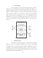
System Boundary
Identification of the system boundary was then stated.
The System
Boundary is established so that the development team is constrained in what they will
address for system requirements. For this thesis, we have determined that the system
boundary will be the application software developed to perform requirements of our
customer as stated in the System Functions in Table 1 and use cases below.
Our system boundary constraint is the software system itself. Within this
boundary lies the process of generating one new T-Rating report; the EDVR is updated
once, AMD verified once, NEC Award Date verified once and a T-Rating report is
generated and output once. In the use of this application, one AMO will be using only
one session of our application at any given time. It is a stand-alone application at the user
end. No network or connection of any kind is assumed to exist between more than just
one AMO.
24
c.
System Functions
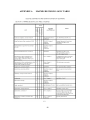
Lastly, system functions were determined by reviewing established
requirements as listed in chapter two of this thesis and from survey responses.
A
complete list of systems functions (what the system must do/perform) is displayed in
Table 1. Also listed are attributes, details and constraints, and categories.
Function
Category Attribute
Import EDVR
Access file to
Relational db
Evident
Interface
Metaphor
Import AMD if
document has been
changed in any way.
Compare individuals
listed in EDVR to
billets listed in AMD
to “fill” the slots.
Capture NEC field
data for individuals
from EDVR.
Capture Rate/Grade
field data from
EDVR.
Capture COB
quantity from
EDVR.
Capture experience
time data.
Evident
Interface
Metaphor
Hidden
Accuracy,
Interface
Metaphor
Hidden
Hidden
Accuracy,
Interface
Metaphor
Accuracy
Hidden
Evident
R1.1
R1.2
R1.3
R1.4
R1.5
R1.6
R1.7
R1.8
Capture BNEC.
Hidden
Details &
Constraints
Forms window
should be easy to
interface to import
and initiate system
procedure.
Notification when
complete.
Notification when
complete
and
version.
None, but notify
when complete.
Category
Must
Must
Must
None, but notify
when complete.
Must
None, but notify
when complete.
Must
Accuracy
None, but notify
when complete.
Must
Interface
Metaphor
Fault
tolerance
Provide window for
AMO to enter
verification criteria.
Must
Accuracy
25
Must allow
verification saves if
there is a break in
the processing.
None, but notify
when complete.
Must
Capture data for
R1.9 input from to Wing
MO (see example).
Adjust inventoryR2.1 manning levels as
necessary.
Log, monthly, status
of manning levels
R2.2
and training levels.
Evident
Accuracy
Fault
tolerance
Interface
Metaphor
Notify upon
completion.
Must
Use data for MRating report.
Want
Evident
Interface
Metaphor
Evident
Interface
Metaphor
Accuracy
Hidden
Accuracy
Hidden
Fault
tolerance
Capture T-Rating of
all rates broken out
R2.6
per Wing MO’s
categorization.
Provide output report
to Wing MO (export
R3.1 of data)
Evident
Accuracy
Evident
Interface
metaphor
Generate report of
combined data for
R3.2
entire Wing (all
squadrons).
Generate spreadsheet
in color codes to
R3.3
indicate levels of
qualification.
Evident
Interface
metaphor
Accuracy
Evident
Interface
metaphor
Compile historical
Want
records by month of
completed
processing.
Create a log of
Want
when reports
generation
completed and
when forwarded.
Data is sensitive in
Must
nature and should
be made
appropriately
secure.
Back-ups should be Must
prompted to be
made on additional
media.
Upon completion of Must
calculations,
notification should
occur.
Options TBD still.
Want
Could be e-mail,
hard copy or direct
input to central
database.
Pertains to the
Must
Wing MO’s master
database for all
squadrons.
Per Wing MO, a
Want
stoplight style chart
is desirable.
Log exported report
to Wing MO.
Hidden
R2.3
DB must be secure
due to readiness
R2.4 level/sensitivity
nature of data.
R2.5
Provide a persistent
storage mechanism.
26
Search criteria
should be by 1)Rate,
2)Pay grade,
R3.4
3)Month (i.e. current
month, POB1,
POB2,…)
Link Access from
the client to the
Wing MO’s db to be
R3.5 able to directly input
data.
Evident
Interface
metaphor
Evident
Interface
metaphor
Fault
tolerance
Table 1.
d.
Allow options to
sort report once
generated.
Further completion
may include this
capability.
Encryption and
receipt verification
should be
considered.
System Functions
Want
Want
High Level Use Cases
One of the best methods used to gain a better understanding of
stakeholders’ needs and system requirements is through the utilization of use cases. Use
cases are descriptions of processes that will occur within the system. There are two
general types of use cases: High Level and Expanded. Initially, use cases are completed
at a high level and are used to describe processes briefly and generally. Expanded use
cases are used later in requirements analysis for further decomposition. The list of use
cases considered follows:
1. Wing MO imports subordinate squadron data to populate the database.
2. Wing MO reviews report generated of old data and new data for
exceptions, changes, and correctness.
3. AMO populates T-Rating calculations with appropriate data from the
AMD.
4. AMO populates T-Rating calculation with appropriate data from
NITRAS, more specifically, NEC award dates.
5. Wing MO populates/updates working Wing T-Rating database with
new data from squadrons.
6. Wing MO has report generated from updated database to exhibit new
T-Rating levels of all squadrons.
7. Squadron AMO downloads/imports current EDVR from EPMAC.
8. AMO populates T-Rating database with appropriate new data from
EDVR.
27
9. AMO generates new T-Ratings to provide to Wing MO.
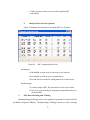
10. AMO builds a new report to provide to Wing MO off new EDVR data.
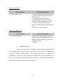
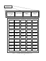
Ultimately, we narrowed the high-level use cases down to just three in
order to focus more on the essence of our system functions. The three high-level use
cases decided upon were 1) Import EDVR (corresponding to item #7), 2) T-Rating
Update (corresponding to item #9), and 3) Wing MO T-Rating Update (corresponding to
item #5) due to their importance and influence in affecting the overall system:
Use Case:
Import EDVR
Actor:
AMO (initiator), EPMAC, or Personnel Division
Type:
primary
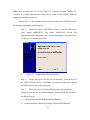
Description: An AMO imports/updates the current EDVR. He opens the
Access database and saves it as his new database filename. The old file (last month’s) is
archived and the current file data is now written into the core tables, queries and reports.
Use Case:
T-Rating Update
Actor:
AMO
Type:
primary
Description: The AMO, once a new EDVR is received, will then update
the Wing MO on the squadron’s T-Rating. The T-Rating should take existing data from
current databases (i.e. EDVR, AMD, NTMPS, TFMMS, and NITRAS) and combine
them to build the report. Once the updated T-Rating is calculated, it will then be sent to
the Wing MO so he can update the T-Rating Wing wide.
Use Case:
Wing MO T-Rating Update
Actor:
Wing MO, AMO
Type:
secondary
Description: The Wing MO receives an updated T-Rating from each
squadron AMO. Highlighted exceptions/changes are reviewed. Updated T-Rating report
is generated from the updated database to display new T-Rating levels of entire Wing.
This report should be viewable under a variety of sorting options.
28
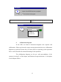
e.
Use Case Diagram
Use case diagrams are used to illustrate entities related in a process.
Actors, use cases, system boundaries, and relations are described in these diagrams. An
illustrated description of what users are involved with the system is given with use case
diagrams. From these diagrams, it is easy to see the relations between users and the
system and how they interact. It is also a quick way to depict the system boundary,
which is shown as the box surrounding the use cases. In our application, the critical
stakeholders are also the users in our T-Rating Update model. Figure 3 shows how these
users are connected through the system boundary and which use cases are pertinent to
each user.
T-Rating Use Case
Import EDVR
T-Rating
Updated
AMO
EPMAC or Personnel
W ing M O T-Rating
Updated
W ing MO
Figure 3.
f.
Use Case Diagram
Expanded Use Cases
In the process of refining requirements, a subsequent step to developing
high-level use cases is the creation of expanded use cases.
Here, a more detailed
examination of what is to occur in the process is described. Expanded use cases differ
from high level ones in that their documentation includes a “Typical Course of Events”
section where the process is more specifically described step-by-step. Listed below is the
expanded use case for the Import EDVR use case.
29
Section:
Main
Use Case:
Import EDVR
Actors:
AMO (initiator), EPMAC, or Personnel Division
Purpose:
Import the most current version of the EDVR to the
T-Rating database.
Overview:
An AMO decides to update/import the current
EDVR. He opens the Access database file and
archives the existing database. Then he opens the
update file and saves it as his new database
filename. The current file data is now written into
the core tables, queries, etc…
Type:
primary and essential
Cross References:
Functions:
Typical Course of Events
Actor Action
System Response
1. This use case begins when the new
EDVR is sent to the AMO from either
EPMAC or Personnel Division.
2. The AMO opens the new database file.
AMO places new EDVR in
the appropriate folder for import.
•
AMO imports new EDVR
into PC-EDVR.
•
AMO
opens
T-Rating
application.
•
3. Determines if EDVR file date is newer
than the existing database file date.
4. If file is more current, prompt to
“update now?”
a. If “yes”, see section “Update File”.
b. If “no”, see section “No Update Now”.
c. If “cancel”, see section “Cancel”.
30
Section: Update File
Actor Action
1. The user selects “yes”.
System Response
2. Notify user that first, the old file will be
archived to archive folders, then execute
archive process.
3. Notify user that new file will be
imported and will overwrite and save as
current file, then execute import process.
4. Notify user that Refresh must be
selected in order to update queries, reports,
etc…
5. Notify user when complete.
Section: No Update Now
Actor Action
1. The user selects “No”.
g.
System Response
2. Notify user “Update not initiated” and
display message recommending the file be
updated as soon as possible. Remind user
to update in 3 days.
3. Close.
Ranked Use Cases
The use cases then need to be ranked in order to determine which should
be decomposed first. Those use cases that more directly affect the core architecture of
the process should be addressed first.
The ranking scheme may be complex and
algorithmic or it may use a simple fuzzy logic classification such as high-medium-low.
Since we are dealing with primarily three use cases here, a simple fuzzy classification
will suffice resulting in the priorities listed in Table 2.
31
Rank
Use Case
Justification
High
T-Rating Update
This is the pivotal process of
this application.
Medium
Import EDVR
Important process; results
fed into over-arching goal.
Low
Wing MO T-Rating Update
Primarily an output of the
previous two use cases.
Low
Start Up*
Definition is dependent on
other use cases.
Low
Shut Down
Minimal effect on
architecture.
Table 2.
h.
Ranked Use Cases
T-Rating Update Expanded Use Case
In our development process, we have performed an iterative development
cycle around the decomposition of our three use cases. The first cycle will undoubtedly
be course; however, after iterations where improvements are implemented, refined
system application procedures will eventually be achieved. As listed in Table 2, it can be
seen that use case priority one is the T-Rating Update use case. With this, an expanded
T-Rating Update – version one use case was created.
T-Rating Update – Version 1
Simplifications, goals, and assumptions
•
Implement EDVR fields only.
•
No calculations.
•
Focus on one UIC for this case.
•
Auto-import from existing file into this.
•
AMO does not have to log in—no access control.
•
There is no record overwriting or archiving requirements.
•
Date of file/report and UIC updated for all outputs.
•
AMO name and e-mail/phone listed on outputs.
•
Completed T-Rating Updates are saved as current database and previous
month’s data is archived to an archive file.
32
Use Case:
T-Rating Update – version 1
Actors:
AMO (initiator), EPMAC or Personnel
Purpose:
Import data from EDVR for T-Rating Update
Overview:
An AMO decides to update T-Ratings. The AMO
records/inputs the appropriate fields/data to the new
T-Rating database. On completion, a report is
generated, the ratings are calculated, and output is
generated to the Wing MO.
Type:
primary and essential.
Cross Reference:
Functions: R1.1, R1.4, R1.6, R1.9, R3.3
Typical Course of Events
System Response
1. This use case begins when an AMO sits
down at the PC to update the T-Rating
report.
2. The AMO opens the T-Rating
application.
3. Query user to see if they would like to
update the T-Rating report now.
4. AMO selects “yes” to update.
5. System updates database from new files.
Old file is archived as a “filename_old”
file.
6. Notifies user that process is complete
and that archive file now saved as
“filename_old” in archive folder.
7. Logs completed actions.
8. AMO logs out and T-Rating database
has now been updated with new EDVR
data.
i.
Conceptual Model and Decomposition
In order to facilitate the identification of concepts within this thesis, the
utilization of a Concept Category List is presented. The goal of creating a conceptual
model is to identify meaningful concepts in the domain of our process. The Concept
Category List is used as a brainstorming tool. Quite often, concepts are missed in the
early identification phase, and then later discovered during the design phase. To prevent
this from occurring as much as possible, a list of more, rather than fewer, concepts is
33
used. From the Concept Category List in Table 3, it can be seen that there are numerous
concepts to consider.
Concept of Category
physical or tangible objects
Examples
Computer
Report
specification, designs or descriptions of
things
T-Rating Report Specifications
places
Squadron
T-Rating Report Descriptions
Wing MO’s Office
transactions
Import, Archive (store), Download,
Calculate/Compute, Write, Output, Display,
Notify
transaction line items (i.e. SalesLineItems)
EDVRFileItem
AMDFileItem
NECAwardDateItem
roles of people
AMO (user)
Wing MO
containers of other things
Database (contains files)
Memory (contains files/report)
Report (contains file data)
things in a container
Record data
Files, database
Reports
other computer or electro-mechanical
systems external to our system
EPMAC, NITRAS, AMD (NTMPS),
TFMMS, PC-EDVR
abstract noun concepts
Knowledge
Insight
Foresight
Projection
Manpower Management
34
organizations
EPMAC (New Orleans), NTMPS
(Pensacola), Squadron, Air Wing,
Personnel Division, Maintenance
Department
events
EDVR receipt, EDVR update, T-Rating
Calculation, AMD date verification, NEC
Date Verification, File Archival,
Notification, Report Generation, Output
Forwarding
processes (often not represented as a
concept, but may be)
EDVR receipt, EDVR update, T-Rating
Calculation, AMD date verification, NEC
Date Verification, File Archival,
Notification, Report Generation, Output
Forwarding
rules and policies
T-Rate
policy:
T-1 = NEC + Cruise Experience
T-2 = NEC + Work Up Experience
T-3 = NEC Awarded
T-4 = Wrong NEC or no NEC
catalogs
NEC catalog
Work center catalog
Area catalog
records of finance, work, contracts, legal
matters
N/A
manuals, books
OPNAVINST 1000.16H, EDVR Users’
Manual, CSEC, NEC manual, NAMP
OPNAVINST 4790.2H
Table 3.
2.
Concept Category List
Analyze Phase
A major transition now occurs – the build phase appears on the horizon. In the
build phase, iterative development cycles occur as well. Then an analyze phase or
analysis phase is started, within which the problems of the current cycle are closely
investigated.
a.
Initial Concept Model
35
The most critical model to develop during the analysis phase is the
Conceptual Model. The conceptual model is important because it is from here that
objects begin to take form for use in the design phase. The conceptual model basically
illustrates the meaningful concepts taken from the Concept Category List and displays
them in no particular fashion - the Concept Category List was merely used as a tool in
generating concepts. Table 4 below is a list of the concepts considered pertinent to our
application.
While all concepts listed below are not critical system process concepts,
for documentary purposes, we have listed them. Ideally, the identification of concept
objects is derived from expanded use cases. In this case; however, it was our desire to
review all potential concepts in this process for reasons discussed in paragraph 1.i above.
b.
Associations
Associations describe how concepts are related to each other.
It is
important to distinguish relationships that need to be established for an indefinite period
of time regardless of duration. We have created a Common Associations List as a tool to
aid in identification and definition of associations here. This list may be viewed in its
entirety in Appendix B. Next, from this list, we then illustrated these associations, in
relation to the concepts in the Conceptual Models. The individual diagrams resulting
from this process may be viewed in Appendix C. In an effort to condense these separate
conceptual models down to one that was concise and easier to convey the domain with
which we are dealing, the Automated T-Rating Conceptual Model with associations was
created as shown in Figure 4.
36
Application Software
Development
Analysis Use
Case Mode
System Behavior
Mode
Conceptual Model
Analysis State
Model
Computer
T-Rating Report
T-Rating
Specification
T-Rating
Description
Squadron
Wing MO's Office
EDVR File Item
AMD File Item
NEC Award Date
Item
AMO (user)
Wing MO
Manpower
Database
Memory
NTMPS
EPMAC
NITRAS
AMD (NTMPS)
TFMMS
PC-EDVR
Area Description
Air Wing
Personnel
Division
Maintenance
Department
EDVR Receipt
EDVR Update
T-Rating
Calculations
AMD Verfication
NEC Date
Verification
File Archival
Notification
Report
Generation
Output
Forwarding
T-Rate Policy
NEC Catalog
Work Center
Catalog
Area Catalog
EDVR
AMD
NITRAS
AMO's Database
Wing MO's
Database
OPNAV
1000.16H
EDVR Users'
Manual
CSEC
NEC Manual
(OPNAV )
NAMP (OPNAV
4790.2H)
Hangar
File
NEC Description
Workcenter
Description
Table 4.
Conceptual Objects (from Larman, p. 103)
37
Figure 4.
Contained-in
1
Concept Model and Associations
38
Given-upon
1
1
1
1
Notification
Given-upon
Given-upon
1
1
Initiates
1
1
1
1
*
Captured-on
Contains-item sof
*
Contains-item sof
1
1
*
*
Contained-in
*
*
AMD
1
1
Verified-via
1
PC-EDVR
NTMPS
EPMACCode49
(orNTPMS)
Downloaded-via 1
1 Downloaded-via 1
1
NECDateVerification
1
1
1
EDVR
MSAccess
Contained-in 1
*
1
W ingMO
Produced-in 1
EDVRFileItem s
1
1
Recorded-in
AMDFileItem s
*
1
Report
Given-upon
1
1
1
1
Captures-report-in
1
Output-to
ManpowerDatabase
Managed-by
1 Manage
s
1
NECDateVerificationItem s
1
Contains-item sof
1
T-RatingCalculations
AMO
1
Captures-report-in
Contains
EDVRUpdate
1
1
se
es
oc
P r -b y 1
d
1
Contains
1
1
EDVRReceipt
1
T-RatePolicy
Automatic T-Rating Conceptual Model
Applies-to
Contains
As with the creation of concepts, when defining associations, concern
should not be given to whether the association will be used during design and
construction. The goal is to establish associations between concepts that have been
created.
In generating associations for this application, the following guidelines
were used:
•
Focus on those associations for which knowledge of the relationship needs
to be preserved for some duration (“need-to-know” associations).
•
It is more important to identify concepts than to identify associations.
•
Too many associations tend to confuse a conceptual model rather than
illuminate it. Their discovery can be time-consuming, with marginal
benefit.
•
Avoid showing redundant or derivable (common sense) associations.
c.
Discussion of Conceptual Model Attributes
At this point, it is beneficial to identify the attributes of the concepts that
are needed to satisfy information requirements of current use cases under development.
An attribute is a logical data value of an object. Attributes are shown in the lower section
of the concept box of Figure 5. A complete list of statements supporting the reason
behind each attribute may be found in Appendix D. It is desirable to have such a list
drawn up in order to see, very quickly, where the relation occurs and why it is important
that each attribute be listed for the related concept.
Taking these concepts, associations, and attributes we arrive at the final TRating Conceptual Model as illustrated below in Figure 6. It should be noted here, that
there is no such thing as a “right” or “wrong” concept model. Conceptual models should
be used as tools to understand and establish the requirements of the system. Better
models make it clearer for people to see overall, how the system will be designed, based
on known information.
With this, we can see what the final T-Rating Conceptual Model, with
associations and attributes, will look like and from which we can then analyze and gain
further understanding of for the design phase. Figure 6 depicts this final diagram.
39
T-R ating C oncept Attributes
EDVR
EDVRUpdate
+date : Date
+uic : Integer
+date : Date
+time : fixed(idl)
+uic : Integer
EDVRFileItem
+uic : Integer
+rate : String
+cob : Integer
+eda/l : Date
+nec1 : Integer
+nec2 : Integer
+a/c t/m/s : String
+area : String
AM O
NTM PS
PC-EDVR
M SAccess
T-RatePolicy
T-RatingCalculations
W ingM O
Report
+rank : String
+nam e : String
+command : String
+uic : Integer
+phone : Integer
+e-mail : String
+date : Date
+tim e : String
+uic : Integer
+com mand : String
+subm itted by : String
+edvr date : Date
+am d date : Date
M anpow erDatabase
AM DFileItem
+rank : String
+name : String
+comm and : String
+uic : Integer
+phone : Integer
+e-mail : String
+area : String
+experience : String
+uic : Integer
+bsc : Integer
+bnec : Integer NECDateVerificationItem
+brate : String +date : Date
+tim e : String
+nam e : String
+rate : String
EPM ACCode49 (orNTM PS)
+uic : Integer
+ssn : Integer
+nec1 : Integer
+nec2 : Integer
NECDateVerification
+date awarded : Date
+experience : String
Figure 5.
Concept Attributes
40
EDVR
+date : Date
+uic : Integer
AM D
+date : Date
+uic : Integer
Notification
+date : Date
+tim e : fixed(idl)
+title : String
Figure 6.
+date : Date
+uic : Integer
EDVRReceipt
Contained-in
41
EDVRUpdate
Conceptual Model with Attributes
G iven-upon
+date : Date
+tim e : fixed(idl)
+title : String
Notification
Produced-in
EDVRFileItem
Given-upon
Given-upon
Given-upon
Contained-in
Contained-in
+date : Date
+uic : Integer
EDVR
MSAccess
+date : Date
+uic : Integer
AMD
W ingMO
Downloaded-via
Downloaded-via
+rank : String
+nam e : String
+com m and : String
+uic : Integer
+phone : Integer
+e-m ail : String
PC-EDVR
NTMPS
NECDateVerification Verified-via EPMACCode49 (orNTMPS)
Contained-in
+uic : Integer
+rate : String
+cob : Integer
AMDFileItem
+eda/l : Date
+uic : Integer
+nec1 : Integer
+bsc : Integer
+nec2 : Integer
+bnec : Integer +a/c t/m /s : String
+brate : String +area : String
Contains
Contains-item s-of
Contains-item s-of
Contains-item s-of
+date : Date
+tim e : String
+nam e : String
+rate : String
+uic : Integer
+ssn : Integer
+nec1 : Integer
+nec2 : Integer
+date awarded : Date
+experience : String
NECDateVerificationItem
C ontains
+date : Date
+tim e : fixed(idl)
+uic : Integer
Captured-on
+date : Date
+tim e : String
+uic : Integer
+com m and : String
+subm itted by : String
+edvr date : Date
+am d date : Date
Report
ManpowerDatabase
Captures-report+area : String
Captures-report-in
in
+experience : String
Manages
Output-to
Processed-by
+rank : String
+nam e : String
+com m and : String
+uic : Integer
+phone : Integer
+e-m ail : String
T-RatingCalculations
Applied-to
Initiates
T-RatePolicy
AMO
Managed-by
Automated T-Rating Conceptual Model w/Attributes
Contains
d.
System Sequence Diagrams
The use of System Sequence Diagrams is important in the analysis phase
because they depict, in the UML notation, the important functions of the system
processes and how they are related to the users, or Actors as they are termed in the UML
notation. Other important factors that are identified in the diagram are things such as the
use case, event orders, and intersystem events. Emphasis should be given to events that
reach beyond the system boundary, depicted as an outlined box that contains use cases.
Things outside this boundary are considered external, such as the actors in our case. One
additional issue that is considered here is that of system behavior.
This behavior is what
is important and describes more of what a system does rather than how it is done. Figure
7 illustrates the use case from the perspective of the AMO and the system events. Figure
8 illustrates the use case from the perspective of the Wing Maintenance Officer.
42
Automated T-Rating System
Sequence Diagram
:System
AMO
addEDVR()
For the EDVR update, the AMO
records the UIC, Rate, COB, EDA/L,
NEC1, NEC2, A/C T/M/S and Area.
addAMD()
For the AMD, the AMO records the
UIC, BSC, BNEC, BRate, AMD Date.
From the NEC Date Verification, the
AMO records the date NEC awarded
and experience amount.
addNECDateVerification()
On completion of record entries, the
AMO indicates to the Application that
the input is complete.
endCalculations()
Figure 7.
AMO System Sequence Diagram
43
Automated T-Rating System
Sequence Diagram
:System
WingMO
Upon completion of the T-Rating
Calculation, a T-Rating Report is
output to the Wing MO.
Figure 8.
makeOutput()
Wing MO System Sequence Diagram
44
From the system sequence diagrams, it can be seen that the system will
have four input messages and one output message, which make up the five system
operations. These operations are explained as a system response to an event initiated by
an external input such as an actor. Figure 9 depicts in the UML notation the five system
operations that will need to be performed.
:System
addEDVR()
addAMD()
addNECDateVerification()
endCalculations()
makeOutput()
Figure 9.
e.
System Operations
Contracts
The last aspect of the analyze phase that needs to be considered is that of
contract creation. Contracts are created to detail what more specifically should happen in
the system operations. They are more ideally the process of what happens in the events
that will take place in terms of state changes from before the event operation to after the
event. In essence, a contract is used to capture the behavior of the system in more detail
so that the developer can start to move toward the next phase where building begins.
A description of each section of a contract is shown in the following
schema of Table 5. Not all sections are necessary, although the Responsibilities and
Post-Conditions sections are recommended.
Name:
Responsibilities:
Type:
Cross References:
Notes:
Exceptions:
Output:
Pre-Conditions:
Post-Conditions:
Name of operations and parameters.
An informal description of the responsibilities this operation must fulfill.
Name of type (concept, software class, interface)
System function reference numbers, use cases, etc.
Design notes, algorithm, and so on.
Exceptional cases.
Non-UI outputs, such as messages or records that are sent outside of the system.
Assumptions about the state of the system before execution of the operations.
The state of the system after completion of the operation.
Table 5.
Contract Schema
45
Contracts pertinent to the Automated T-Rating system operations are the adding
of the EDVR to the system database, adding the AMD to the system database, adding the
NEC Date Verification to the database, ending the Calculations when all EDVR, AMD
and NEC Date data is present, and lastly, making output as in the form of reports.
Name:
addEDVR
Responsibilities:
Enter (record) the newly received EDVR file for use in the TRating Calculation.
Type:
System
Cross References:
System Functions: R1.1, R1.3, R1.4, R1.5, R1.6
Notes:
Exceptions:
Output:
Pre-conditions:
EDVR file is saved to a specific location in order for system to
address it for import.
Post-conditions:
•
If a new T-Rating calculation, a T-RatingCalculations was created.
•
A T-RatingCalculationLineItem was created.
•
If a new T-Rating calculation, the new T-Rating was associated with the
Manpower Database (association formed).
•
The EDVRLineItem was associated with the T-Rating Calculations.
•
If EDVR import was completed, a Notification message was created.
Name:
addAMD
Responsibilities:
Enter the AMD data for use in the T-Rating Calculation.
Type:
System
Cross References:
System Functions: R1.2, R1.3, R1.9
Notes:
Exceptions:
Output:
Pre-conditions:
AMD is saved to a specific location in order for system to address
it for import.
46
Post-conditions:
•
If a new T-Rating calculation, a T-RatingCalculations was created.
•
If a new T-Rating calculation, a T-RatingCalculationLineItem was created.
•
The T-Rating was associated with the Manpower Database.
•
An AMDLineItem was created.
•
The AMDLineItem was associated with the T-RatingCalculations.
•
If AMD import was completed, a Notification message was completed.
Name:
addNECDateVerification
Responsibilities:
Enter the NEC Award Date for use in the T-Rating Calculation.
Type:
System
Cross References:
System Functions: R1.8
Notes:
This is a process that may require a number of repetitive cycles as
each individual’s NEC award date will need to be verified;
something that may not be performed in one step.
Exceptions:
Output:
Pre-conditions:
Members already onboard have been verified. Only new gains will
require verification.
Post-conditions:
•
If a new T-Rating calculation, a T-RatingCalculation was created.
•
If a new T-Rating calculation, A T-RatingCalculationLineItem was
created.
•
The T-Rating was associated with the Manpower Database.
•
An NECDateVerificationLineItem was created.
•
The NECDateVerificationLineItem
RatingCalculation.
•
If NECDateVerification was completed, a Notification message was
created.
47
was
associated
with
the
T-
Name:
endCalculations
Responsibilities:
Record that it is the end of entry of T-Rating items, and display TRating report totals.
Type:
System
Cross References:
System Functions: R2.6.
Notes:
This is notification to the system that all entries for the T-Rating
Calculation are complete; processing may commence now.
Exceptions:
Output:
On-Screen visual notification.
Pre-conditions:
EDVR, AMD, NECDateVerification are known to the system.
Post-conditions:
•
T-Rating.isComplete was set to true (attribute modification).
Name:
makeOutput
Responsibilities:
Record the T-Rating Calculation, make output to designated
addressees.
Type:
System
Cross References:
System Functions: R3.1, R3.2, R3.3, R3.4.
Notes:
Exceptions:
Output:
database file, e-mail, hard copy (for binders that may be kept).
Pre-conditions:
Post-conditions:
•
Output is created.
48
3.
Design Phase
In this section, we make the transition to design where the actual concepts of
operation will be drawn out more specifically. Again, we have primarily been concerned
with the what that the system must do. Here, though we start to concentrate on how
things will be processed.
In the design phase, a logical solution is presented to address the issues identified
during the previous two phases of Plan and Elaborate, and Analysis. The pinnacle
element of these two phases is the creation of collaboration diagrams. In collaboration
diagrams, we diagram the process that is to satisfy the requirement so written for. In this
section of the thesis, we present our description of the real use cases, diagram how our
system processes will communicate in the form of collaboration diagrams, and lastly,
summarize the critical links through the creation of the Design Class Diagram.
a.
Real Use Case Description
In the design phase, there are no high-level or expanded use cases.
Instead, these are utilized in terms of real use cases. By real, what is meant is that the use
case’s actual design will be described using concrete input and output, as well as
implementation methodologies. In this instance, we have taken the Import EDVR use
case and described more specifically, using storyboarding, how the use case would be
realized. As is shown, a graphical user interface will be used to provide a means of
communication between the user and the system. At this point, the application is not
fully developed, but with the depiction of the basic GUI windows, it becomes easier to
see how the system may function as well as identify other requirements that need to be
addressed.
49
Typical Course of Action
Actor Action
System Response
1. This use case begins when a new
EDVR has been posted to the LAN by the
Command Career Counselor or Pers Div.
2. The AMO will copy this file into the
folder c:\\prometheus\edvr\import
3. The AMO will double click the 4. Prometheus application will launch.
Prometheus icon to open the application.
5. Prompt user to import new EDVR from
c:\\Prometheus\edvr\import.
Prometheus
Would you like to import a new EDVR for
updating?
Yes
No
6. The system opens the new EDVR .txt
file, and then copies the data/fields into
the Prometheus database.
7. The AMO will select the “yes” button 8. Name of EDVR file should already
to confirm.
exist. Prompt user to rename and archive
the old file
Prometheus
The file edvr.xxx already exists. Do you want to rename and
archive the old file to the archive folder?
Yes
No
9.
Old file will be renamed as
<DD_MMM_YY.___> and moved into the
folder c:\\Prometheus\edvr\archives
10. Notify user that import process has been
complete.
50
Prometheus
Import of new EDVR has been completed.
Don't show this warning again.
11. Prompt user to view or print out new
EDVR.
Prometheus
?
What would you like do now?
View EDVR
OK
Print EDVR
Check AMD Date
Validate NEC Date
Home
b.
Collaboration Diagrams
In the UML, two kinds of interaction diagrams exist: sequence and
collaboration. Either may be used to express message interaction; however, collaboration
diagrams are preferred because they are better suited to expressing system operations
flow as well as describe the contextual meaning of such operations.
The collaboration diagrams use the pre- and post-conditions of the
contracts in section 2.e of this chapter, and illustrate message interactions. A description
of each diagram follows:
51
addAM D Collaboration Diagram
byController
addAMD()
byCreator
1:[newCalculation]create()
:Prometheus
:T-RatingCalculations
3:makeLineItem(unit, bsc, A_PNEC, A_RTABBR, A_GRADE,
amddate)
2:amd:=getAMD(unit, bsc, A_PNEC,
A_RTABBR, A_GRADE, anddate)
byExpert
1.1:create()
byCreator
3.2 add(trc)
:AMD
2.1:amd:=find(unit, bsc, A_PNEC,
A_RTABBR, A_GRADE, amddate)
:CalculationLineItem
:AMDLineItem
3.1create(unit, bsc,
A_PNEC, A_RTABBR,
A_G RADE, amddate)
trc:TRCLineItem
An empty container that will eventually hold calculationLinItem instances
Figure 10.
Add AMD Collaboration Diagram
52
The addAMD collaboration diagram in Figure 10 is read as follows:
1. The message addAMD is sent to an instance of Prometheus.
It
corresponds to the addAMD system operation message.
2. The Prometheus object sends the addAMD message to a TRatingCalculation instance.
3.
The
T-RatingCalculations
object
creates
an
instance
of
CalculationLineItem.
4. The Prometheus object sends the getAMD message to an AMD instance.
5. The AMD object finds the datafields in the AMD and creates an instance
of AMDLineItem called for.
6. The T-RatingCalculations object creates a TRCLineItem with the AMD
data found in the instance of AMDLineItem.
7. The TRCLineItem just created is then added to and stored in the object
CalculationLineItem.
53
addEDVR Collaboration Diagram
byController
byCreator
addEDVR()
1:[newCalculation]create()
:Prometheus
:T -RatingCalculation
3:makeLineItem(ba, cob, eda/l, nec1, nec2, edvrdate)
byExpert
byCreator
2:edvr:=getedvr(ba, cob, eda/l,
nec1, nec2, edvrdate)
1.1:create()
3.2:add(trc)
3.1create(...)
:EDVR
trc:CalculationLineItem
trc:TRCLineItem
2.1:edvr:find(ba, cob, eda/l, nec1,
nec2, edvrdate)
:EDVRLineItem
An empty container that will eventually hold CalculationLineItem instances
Figure 11.
Add EDVR Collaboration Diagram
54
The addEDVR collaboration diagram in Figure 11 is read as follows:
1. The message addEDVR is sent to an instance of Prometheus.
It
corresponds to the addEDVR system operation message.
2. The Prometheus object sends the addEDVR message to a TRatingCalculation instance.
3.
The
T-RatingCalculation
object
creates
an
instance
of
CalculationLineItem.
4. The Prometheus object sends the getEDVR message to an EDVR
instance.
5. The EDVR object finds the data fields in the EDVR and creates an
instance of EDVRLineItem called for.
6. The T-RatingCalculation object creates a TRCLineItem with the EDVR
data found in the instance of EDVRLineItem.
7. The TRCLineItem just created is then added to and stored in the object
CalculationLineItem.
55
addNECDateVerification Collaboration
Diagram
byController
addNECDateVerification()
:Prometheus
byCreator
1:[newCalculation]create()
:T-RatingCalculation
3:makeLineItem(NECAwardDate)
1.1:create()
2:NECDateVer:=getNECDateVer(NECAwardDate)
byExpert
:NECDateVerification
byCreator
:CalculationLineItem
2.1:NECDateVer:=find(NECAwardDate)
An empty container that
will eventually hold
CalculationLineItem
instances.
:NECDateVerLineItem
assuming we can get a NEC Date report from
EPMAC Code 49.
Figure 12.
Add NEC Date Verification Collaboration Diagram
The addNECDateVerification collaboration diagram in Figure 12 is read
as follows:
1. The message addNECDateVerification is sent to an instance of
Prometheus. It corresponds to the addNECDateVerification system operation message.
56
2. The Prometheus object sends the addNECDateVerification message to a
T-RatingCalculation instance.
3.
The
T-RatingCalculation
object
creates
an
instance
of
CalculationLineItem.
4. The Prometheus object sends the getNECDateVer message to a
NECDateVerification instance.
5.
The
NECDateVerification
object
finds
the
data
in
the
NECDateVerification report and creates an instance of NECDateVerLineItem called for.
6. The T-RatingCalculation object creates a TRCLineItem with the NEC
date data found in the instance of NECDateVerLineItem.
7. The TRCLineItem just created is then added to and stored in the object
CalculationLineItem.
57
endCalculation Collaboration
Diagram
becomeComplete()
{
isComplete:=true
}
endCalculations()
1:becomeComplete()
:Prometheus
:T-RatingCalculation
byController
Figure 13.
byExpert
End Calculation Collaboration Diagram
The endCalculation collaboration diagram in Figure 13 is read as follows:
1. The message endCalculations is sent to an instance of Prometheus. It
corresponds to the endCalculations system operation message.
2. The Prometheus object sends a becomeComplete message to a TRatingCalculation instance.
3. The becomeComplete message is a simple, standard message to end
processing.
58
m akeOutput Collaboration Diagram
byController
makeOutput()
byCreator
3:makeOutput(t-RatingReportFields)()
1:[newCalculation]create()
:T-RatingCalculation
:Prometheus
2:get(trc)()
r:T-RatingCalculation
3.1:create()
:Report
:TRCLineItem
Figure 14.
Make Output Collaboration Diagram
The makeOutput collaboration diagram in Figure 14 is read as follows:
1. The message makeOutput is sent to an instance of Prometheus. It
corresponds to the makeOutput system operation message.
2. The Prometheus object creates a T-RatingCalculation object.
3. The T-RatingCalculation object sends the getTRC to the container
CalculationLineItem.
4. The T-RatingCalculation object sends the makeOutput message to the
report object T-RatingCalculation.
59
5. The report object sends a create message to the Report object in the
format desired by the user (i.e. printer or file).
60
startUp Collaboration Diagram
Pass a reference to the EDVR,
AMD, NECDateVerification to
the T -RatingCalculation, so that
it has permanent visability to it.
byCreator
create(edvr, amd, necdate)
:Prometheus
1:create()
1.1:create()
edvr:EDVR
1.2.2*:add trc:edvrfields
1a:create()
1.2:loadEDVRLineItem()
trc:EDVRLineItem
1b:create()
1.2.1*create(cob, eda/l, nec1, nec2, edvrdate, aircraft, ba) trc:edvrfields
1.1a:create()
amd:AMD
1.2a.2* add:trc:amdfields
trc:AMDLineItem
1.2a:loadAMDLineItem()
trc:amdfields
1.2a.1*create (unit, bsc, A_PNEC, A_RTABBR, A_GRADE)
1.1b:create()
necdate:NECDateVerification
trc:NECDateVerificationLineIte
m
1.2b.2* add:trc:necdatefield
1.2b:loadNECDateVerLineItem()
trc:necdatefield
1.2b.1*create(necawarddate)
Asterix in sequence number
indicates the message occurs
in a repeating section.
Figure 15.
Start-up Collaboration Diagram
61
The startup collaboration diagram in Figure 15 is read as follows:
1. The message create( ) is sent to an instance of Prometheus.
2. The object Prometheus sends a create( ) message to instances of EDVR,
AMD, and NECDateVerification.
3. The objects EDVR, AMD, and NECDateVerification send a
load*LineItem message to themselves to initialize these objects for system operation.
c.
Design Class Diagram
In furthering this application from just an idea to real code, we come to the
use of the class diagram. Typical information contained in class diagrams is:
•
classes, associations, attributes
•
interfaces with their operations and constraints
•
methods
•
attribute type information
•
navigability
•
dependencies
Whereas in the conceptual model where objects do not necessarily
represent software definitions, in class diagrams abstractions of these concepts are
defined in terms of software classes and components.
The diagram in Figure 16
describes the information listed above for our application. One note regarding class
diagrams however, they should be created taking into consideration the intended
audience. If a CASE tool with automatic code generation is to be used, then full and
exhaustive details are necessary. But if the class diagrams are being created for software
developers to read, exhaustive detail may adversely affect any intended value added.
62
Design Class Diagram
EDVRLineItem
Prom etheus
-UIC : fixed(idl)
-rate : string(idl)
EDVR
-cob : int
-date
1 Contains 1..*
-eda/l : Integer
-UIC
-nec1 : fixed(idl)
+getEDVR()
-nec2 : fixed(idl)
-edvrDate : String
+addEDVR()()
+addAMD()
+addNECDateVerification()
1
Archives
Looks-in
1
Captures
1..*
1
+find()
T-RatingCalculation
1
-date : Date
-isComplete : Boolean
-time
1
Looks-in
1
1..*
-uic : fixed(idl)
-bsc : fixed(idl)
-bnec : fixed(idl)
-brate : String
Looks-in
Contains
Contains
AM DLineItem
+getAMD()
+makeLineItem()
1
AM D
-date : Date
-uic : fixed(idl)
+find()
NECDateVerification
1
Contains 1..*
+getNECdate()
1..*
T-RatingCalculationLineItem
NECDateVerLineItem
-nedDate : string(idl)
-necQuantity : Integer
-necAwarded : Boolean
-experience : Integer
-date : Date
-time : String
-name : String
-rate : short
-uic : fixed(idl)
-ssn : int
-nec1 : fixed(idl)
-nec2 : fixed(idl)
-date awarded : Date
-experience : int
+add()
+findNECdate()
Figure 16.
Design Class Diagram
63
4.
Summary
In this chapter, we have performed requirements analysis by taking an Object
Oriented Analysis and Design approach. We have used the Unified Modeling Language
to identify, diagrammatically, the objects of the application and how these objects
interrelate with each other in its domain. The goal of this phase of development has been
to identify entities, classes and links so that the software developer may be able to
duplicate as close as possible, the business process ideas of the customer and reproduce
them in code represented by the software application developed in this thesis. The next
step is to begin writing the code necessary to produce something more tangible for the
user.
64
IV.
A.
MICROSOFT® .NET FRAMEWORK, VISUAL BASIC.NET
AND ADO.NET IMPLEMENTATION
INTRODUCTION
The vast majority of applications built today involve data manipulation in some
way—whether it is retrieval, storage, change, translation, verification, or transportation.
For an application to be scalable and allow other applications to interact with it, the
application will need a common mechanism to pass the data between the data provider
and data consumers. Ideally, the vehicle that transports the data should contain the base
data, any related data and metadata, and be able to track changes to the data as well. The
Prometheus application uses the Microsoft® .NET Framework Visual Basic.NET
(VB.NET) and ADO.NET to accomplish these tasks.
There have been many methods of handling data in previous versions of Visual
Basic, beginning with the simple Data Access Objects (DAO) protocol, then Remoteaccess Data Objects (RDO), followed by ActiveX Data Objects (ADO), which has
evolved today into ADO.NET. ADO.NET leverages the power of Extensible Mark-up
Language (XML) to provide disconnected access to data. ADO.NET was designed handin-hand with the XML classes in the .NET Framework—both components of a single
architecture. (Holzner, p. 19)
ADO.NET and the XML classes in the .NET Framework converge in the DataSet
object. The DataSet can be populated with data from an XML source, whether it is a file
or an XML stream. The DataSet can be written as World Wide Web Consortium (W3C)
compliant XML, including its schema as XML Schema definition language (XSD)
schema, regardless of the source of the data in the DataSet.
Because the native
serialization format of the DataSet is XML, it is an excellent medium for moving data
between tiers making the DataSet an optimal choice for remote data access and schema
context to and from an XML service.
65
B.
ADO.NET ARCHITECTURE
Data processing has traditionally relied primarily on a connection-based, two-tier
model.
As data processing increasingly uses N-tier architectures, programmers are
switching to a disconnected approach to provide better scalability for their applications.
The Prometheus application utilizes the two-tier architecture, though it is built upon the
ADO.NET principles laid out in this section for future N-tier implementation and
scalability. (MSDN Library)
Note that ADO is no longer built into Visual Basic.
ADO was based on
Component Object Model (COM) protocols, and COM (as well as DCOM) is no longer
built into Visual Basic either. Instead, ADO.NET uses XML to exchange data. Both
COM and distributed COM (DCOM) technology has been replaced by the .NET
framework. (Holzner, p. 19)
The ADO.NET core components have been designed to factor data access from
data manipulation as illustrated in Figure 17. There are two central components of
ADO.NET that accomplish this: 1) the DataSet and 2) the .NET data provider, which is a
set of components including the Connection, Command, DataReader, and DataAdapter
objects.
The other core element of the ADO.NET architecture is the .NET data providers,
whose components are explicitly designed for data manipulation and fast, forward-only,
read-only access to data. The Connection object provides connectivity to a data source.
The Command object enables access to database commands to return data, modify data,
run stored procedures, and send or retrieve parameter information. The DataReader
provides a high-performance stream of data from the data source.
Finally, the
DataAdapter provides the bridge between the DataSet object and the data source. The
DataAdapter uses Command objects to execute SQL commands at the data source to both
load the DataSet with data, and reconcile changes made to the data in the DataSet back to
the data source. (MSDN Library)
66
Figure 17.
C.
ADO.NET architecture and components
ADO.NET COMPONENTS
ADO is a Component Object Model interface to Object Linking and Embedding
(OLE) DB providers; OLE DB expects to be accessed by consumers such as ADO.
Figure 18 illustrates the OLE DB architecture. Formally, an OLE DB Consumer is any
piece of system or application code that consumes an OLE DB interface, including the
OLE DB components themselves. Figure 19 illustrates how ADO interfaces with the
OLE DB object. (Vaughn, p. 15)
Figure 18.
OLE DB Architecture
67
OLE DB Consumer
ADO 2.X (MDAC)
Service Providers *
Client Cursor Provider
SQL Server
OLE DB
Provider
Oracle OLE
DB Provider
Shape Provider
Jolt/Jet OLE
DB Provider
ODBC OLE DB Provider
Jet Database
Engine
SQL Server
ODBC Driver
Oracle ODBC
Driver
“Other” ODBC
Driver
Data
Data Source
Figure 19.
ADO – OLE DB Object Interface
A provider is any software component that exposes an OLE DB interface. OLE
DB providers can be classified broadly into two classes: data providers and service
components.
A data provider is any OLE DB provider that owns data and exposes its data in a
tabular form as a rowset, which is defined later in this section. Examples of data
providers include relational database management systems (RDBMS), storage managers,
spreadsheets, and service components. Prometheus uses the Jet 4.0 provider, which is the
only native OLE DB provider available to access a Microsoft® Access (DBMS)
database. The Microsoft® OLE DB Provider for Jet provides an OLE DB interface to
Microsoft® Access databases and allows Microsoft® SQL Server™ 2000 distributed
queries to query Access databases. (Vaughn, p. 15)
A service component is any OLE DB component that does not own its own data,
but encapsulates some service by producing and consuming data through OLE DB
interfaces. A service component is both a consumer and a provider. For example, a
68
heterogeneous query processor is a service component - it has to draw data from one
source, restructure it, and pass it up the food chain to the requesting component, the
consumer. (Vaughn, p. 15-16)
A database management system (DBMS) is a type of data source whose job it is
to return information in one form or another as an OLE DB data provider. In the
Prometheus implementation, the DBMS is segmented into functional pieces
(components) - each handling a specific job. In theory, component DBMS’s offer greater
efficiency than traditional DBMS’s because consumers generally require only a portion
of the database management functionality offered, thereby reducing resource overhead.
OLE DB enables simple tabular data providers to implement functionality native to their
tables. (Vaughn, p. 16) Microsoft® Access 2002 was chosen as a stand-alone DBMS for
its powerful management and analyzing capabilities. This application was chosen for
proof of concept primarily, although Access provides full XML support, enabling the
creation of a sophisticated enterprise-wide database solution. The Prometheus E-Pro
Alpha.mdb file can be integrated easily with the Web and ported over to a Microsoft®
SQL Server DBMS with minimal programmatic changes. The following illustration of
Figure 20 shows major components of the ADO.NET application.
Figure 20.
ADO.NET Components
69
1.
DATA PERSISTED AS XML
ADO.NET is a new data-handling model that makes it easy to handle data on the
Internet and on a local machine to communicate with local databases the way Prometheus
does. At the heart of ADO.NET is XML; all data is represented in XML format and
exchanged that way. Prometheus uses XML via the VB.NET application development
environment to translate, verify, and exchange data.
Data needs to be moved from the data store to the DataSet and from there to
various components. In ADO.NET, the format for transferring data is XML. Similarly,
if data needs to be persisted, into a file for example, it is stored as XML. If you have an
XML file, you can use it like any data source and create a DataSet out of it.
In ADO.NET, XML is a fundamental format for data. The ADO.NET data
Application Protocol Interfaces (API) automatically create XML files or streams out of
information in the DataSet and send them to another component. The second component
can invoke similar APIs to read the XML back into a DataSet. The data is not stored in
the DataSet as XML—for example, you cannot parse data in a DataSet using an XML
parser but instead, in another more efficient format.
Basing data protocols around XML offers a number of advantages: 1) XML is an
industry-standard format.
This means that your application's data components can
exchange data with any other component in any other application, as long as that
component understands XML. Many applications are being written to understand XML,
which provides an unprecedented level of exchange between disparate applications.
XML is text-based. The XML representation of data uses no binary information,
which allows it to be sent via any protocol, such as HTTP. Most firewalls block binary
information; however, by formatting information in XML, components can still easily
exchange information.
70
2.
SCHEMA DEFINED DATA STRUCTURES
ADO.NET uses XML directly when working with metadata. Here, DataSets are
represented as XML.
The structure of the DataSet—the definition of what tables,
columns, data types, constraints, and so on are in the DataSet—is defined using an XML
Schema based on the XML Schema Definition language (XSD). Just as data contained
by a DataSet can be loaded from and serialized as XML, the structure of the DataSet can
be loaded from and serialized as XML schema.
The ADO.NET DataSet, represented in Figure 21, is a data construct that can
contain several relational rowsets, the relations that link those rowsets, and the metadata
for each rowset. The DataSet also tracks which fields have changed, stores their new
values, original values, and custom information in its Extended Properties collection.
The DataSet can be exported to XML or created from an XML document, thus enabling
increased interoperability between applications. (MSDN Library)
Connection
DataAdapter
DataSet
SelectCommand
Data Tables
InsertCommand
DataTable
DataTable
Data Rows
Data Rows
Data
Columns
Data
Columns
DeleteCommand
UpdateCommand
Data Relations
Database
Figure 21.
Your Code
ADO.NET DataSet
71
3.
DATA CACHING IN DATASETS
The most common data task is to retrieve data from the database and do
something with it such as display it, process it, or send it to another component.
Frequently, the application needs to process not just one record but a set of them: for
example, a list of sailors or Billet Sequence Codes (BSC). Often the set of records that
the application requires comes from more than one table such as Sailors, Systems,
Assigned Aircraft, and other similar sets of related records as referenced in Prometheus.
(MSDN Library)
Once these records are retrieved, the application typically works with them as a
group. For example, the application might allow the user to browse through all the
SAILOR records and examine their assigned BSC for one or more Sailors, then move to
the next BSC and reassign a new BSC, and so on. (MSDN Library)
In the domain of Prometheus, it is impractical to go back to the database each
time the application needs to process the next record. Doing so would undo much of the
advantages gained by minimizing the need for open connections.
The Prometheus
application therefore, works with a temporary cache of records retrieved from the
database and connects to the database only when required.
A DataSet is a cache of records retrieved from a data source. It works like a
virtual data store. A DataSet includes one or more tables based on the tables in the actual
database, and it can include information about the relationships between those tables and
constraints on what data the tables can contain.
Contained in the DataSet is usually a reduced version of what the database
contains. However, the DataSet can be worked with in much the same way as the real
data. While doing so, the DataSet remains disconnected from the database, which frees it
to perform other tasks.
You often need to update data in the database, although not nearly as often as you
retrieve data from it. You can perform update operations on the DataSet, and these can
be written to the underlying database.
72
An important point is that the DataSet is a passive container for the data. To
retrieve data from the database and write it back, you use data adapters. A data adapter
contains one or more data commands used to populate a single table in the DataSet and
update the corresponding table in the database. A data adapter typically contains four
commands, one each to select, insert, update, and delete rows in the database. Therefore,
a data adapter's Fill method might execute a SQL statement such as SELECT SID,
LastName, FirstName FROM SAILORS whenever the method is called.
Because a DataSet is effectively a private copy of the database data, it does not
necessarily reflect the current state of the database. If you want to see the latest changes
made by other users, you can refresh the DataSet by calling the appropriate Fill method.
One of the advantages of using DataSets is that components can exchange them as
required. For example, a business object in the middle tier might create and populate a
DataSet then send it to another component elsewhere in the application for processing.
This DataSet property means that components do require individual queries of the
database to retrieve related data. (MSDN Library)
D.
PROMETHEUS CORE FUNCTION WALKTHROUGH
1.
Import of the AMD and EDVR Text Files
Importing the AMD & EDVR text files via the Import Wizard is the preferred
method of updating and maintaining the E-Pro Alpha.mdb database with the most current
information available. Figure 22 is an Import Wizard screenshot.
Prometheus can handle multiple imports of the same or dissimilar files. Imported
files can be undone during the file verification process and are not permanent until the
user has specifically accepted them. Once imported, the user can change properties via
many input methods.
The Enlisted Placement Management Center (EPMAC) is the advocate for the
distribution of active duty personnel to enhance the manning readiness of surface,
submarine, aviation and ashore units. EPMAC provides a self-extractable file, formatted
as UIC.exe (i.e. #####.exe). An authorized user of the EPMAC Bulletin Board System
73
(BBS) must download this file via the WildC.A.T Navigator program. WildC.A.T.
Navigator is a simple telnet terminal client used to connect to the EPMAC BBS and
transfer requested files to the user.
After the UIC.exe file download, and the user has extracted the AEEDVR.txt file,
the following importation example applies.
Step 1.
Launch the Import AMD/EDVR Wizard. From the Tools menu,
select Import AMD/EDVR.
The Import AMD/EDVR Wizard will
automatically load with default values selected and display a welcome screen.
Click Next > to continue the wizard
Figure 22.
Step 2.
Import Wizard Welcome Screen
Choose the type of text file you are importing. Valid choices are
the AMD or EDVR text files. Click Next > to continue and the import wizard
will display the file type selection dialog.
Step 3.
When the Verify File Dialog Window opens, the wizard will
attempt to locate the file in its default location. For the EDVR file, it looks in
the following order:
1. C:\Program Files\PCEDVR\Import\AEEDVRBB.txt
2. %Install Prometheus Directory%\Import\EDVR\AEEDVRBB.txt
74
3. The last known location where the file was previously opened.
NOTE: If the file is found, the Import Wizard will enable the Next > button
for you to continue. If the file is NOT found, or you wish to change the
location of the file, you must select the New Connection button, where you
much select a new source file to be imported.
Step 4.
Next, you must set up any preferences for importing the file. You
will be stepped through two screens. After you have made your choices, click
the Finish button to begin importing records.
NOTE: At the end of the wizard, regardless of your choices, you can undo,
reject, or accept any additions made to the file prior to saving data to your
database.
Step 5.
The Import Wizard will import and format EDVR data. When
complete, you will be notified and must click the Next > button to finish the
wizard and load the EDVR Verification Window where you can view, edit,
accept or reject the imported records as a group or individually.
The Activity Manning Document (AMD) is the single authoritative source for an
activity’s statement of manpower requirements (SMR) and manpower authorizations
allocated to perform assigned missions. Navy Training and Management Planning
System (NTMPS) at Pensacola, Florida provides access to their manpower databases via
the Citrix© Independent Computing Architecture (ICA) Client. Prometheus provides a
formatted query to be used by an authorized user of the NTMPS database. This file
produces the AMD.txt file required for the AMD import wizard. Once the query file is
ran on the NTMPS database via Citrix ICA Client, the created query file can be stored
locally and imported similarly to the EDVR example.
2.
Assisted Assignment of the BSC to the Sailor Record
Billet Sequence code assignment is a primary function of the AMO. The Activity
Manning Document is the single authoritative source for an activity’s Statement of
Manpower Requirements (SMR) and manpower authorizations allocated to perform
75
assigned missions. More importantly to users, the AMD houses their command's
applicable Billet Sequence Codes (BSC).
The AMD text file must be imported via the Import AMD/EDVR Function prior
to assigning BSCs to your personnel. Until a successful import has taken place, the
available BSCs will be blank. See how to Import the AMD into Prometheus for more
details. Prometheus provides two methods for assigning BSCs to a Sailor.
a.
Single Sailor Record Assignment
Figure 23 illustrates the data form provided for assigning a BSC to a
single SAILOR record.
Figure 23.
BSC Assignment Form
Advantages:
•
Simple edit of single record in an easy-to-use interface.
•
Records are sorted alphabetically by Last Name.
•
Only available BSCs are displayed based on your choice of Rate,
Rating, or NEC.
•
Assistance tools are made available for your convenience.
Disadvantages:
•
You must assign a BSC to each sailor individually.
76
If there are many sailors, you must still assign the BSC
individually.
•
b.
Multiple Sailor Record Assignment
Figure 24 illustrates the data grid for assigning BSCs to all Sailors.
Figure 24.
BSC Assignment Data Grid
Advantages:
• Edit multiple records at once in an easy-to-use interface.
• Sort multiple records by your own preferences.
• Fast and effective means for editing numerous records at once.
Disadvantages:
• You must assign a BSC_ID (chosen from a list) to each sailor.
• There is no error checking for assigning an unqualified sailor to a
particular BSC.
3.
NEC Data, M-Rating and T-Rating
Manning Rating (M-Rating) refers to the quantity of personnel Current-On-Board
per Billets Assigned (COB/BA). Training Rating (T-Rating) references a sailor’s training
77
level and years of experience in their current NEC. Figure 25 illustrates the primary data
form used for viewing and printing NEC and rating datum calculations.
Figure 25.
NEC/Rating View/Print Form
The primary data form, Prometheus – Rating Reports & Views, incorporates three
primary tools for user interaction with the database: Save/Export Data to Excel, Print
NEC and Rating Views and Edit NEC Data.
4.
M-RATING COMPUTATION
Prometheus accomplishes the M-Rating calculation for a specific activity by
evaluating the number of personnel onboard and comparing that information to the
authorized billets assigned to that activity.
Prometheus provides two options for
displaying M-Rating datum calculations: by period (nine-month projection) and by
aircraft type.
Prometheus uses the following simplified algorithm to accomplish this
comparison:
a) Check each record’s values for COB and BA (Yes = 1, No = 0) and
record these values to a corresponding System and Aircraft type.
These values are stored in a 3-dimension array. The 3-dimension array
allocates record keeping space for 14 system types, 10 aircraft types,
and COB and BA values for each record.
78
b) Prometheus checks desired output type—by period or by aircraft type.
If by period, Prometheus permits only one aircraft type. Prometheus
therefore calculates a ten-month projection. Note: these values equate
to POB1 through POB9 where the tenth value is the actual COB of
today’s date. If by aircraft type, Prometheus dimensions each system
type to its corresponding aircraft type.
c) Prometheus evaluates the stored values in the 3-dimension array and
calculates the M-Rating.
Prometheus then inserts these M-Rating
calculations into a datagrid object on the M-Rating View tab.
The user initiates the M-Rating and T-Rating calculations when the form is
loaded.
Note: During testing of the function, only a small fraction of the sailors were
assigned BSCs.
5.
T-RATING COMPUTATION
The T-Rating computation was not a requirement of the Prometheus application,
though we have incorporated it as a potential future program option. The T-Rating
computation is average score given to each system of a particular aircraft over a ninemonth projection. Each record or sailor’s score relates to these current standards: T-1
equates to NEC awarded plus two years of experience; T-2 equates to NEC awarded plus
six months of experience; T-3 equates to NEC awarded; T-4 equates to no NEC or
incorrect NEC awarded.
E.
SUMMARY
Prometheus is a distributed, front-end database client application that utilizes the
Microsoft© .NET Framework and Visual Basic .NET to meet its development needs. At
the heart of the Prometheus application is ActiveX Data Objects for the .NET Framework
(ADO.NET). ADO.NET is a set of classes that expose data access services to the .NET
programmer. Utilization of sound, object oriented ADO.NET, and .NET practices will
afford the Prometheus application easy portability to a middle-tier business object that
can be readily integrated into a professional n-tiered business model.
79
ADO.NET was designed to meet the needs of this new programming model:
disconnected data architecture, tight integration with XML, common data representation
with the ability to combine data from multiple and varied data sources, and optimized
facilities for interacting with a database, all native to the .NET Framework. (MSDN
Library)
This chapter outlined the fundamental components and object models of
ADO.NET employed in the Prometheus application, as well as give a brief explanation of
data-access and data handling through ADO.NET and XML resources within the .NET
Framework.
80
V.
A.
CONCLUSIONS AND RECOMMENDATIONS
CONCLUSIONS
As a result of this study, we have arrived at conclusive answers to questions
presented in Chapter I.
As circumstances currently stand today, gaining knowledge regarding the
status of manpower within an activity is a manual, complex, and
cumbersome process. Would it be possible to develop an application that
could automatically read and import data from an activity’s EDVR and
compare it with the standing AMD at various milestone points of a
deployment/turnaround cycle to produce a report of overall T-Ratings (a
rating based on an individuals training level and years of experience in
current Navy Enlisted Classification (NEC) Code) and M-Ratings (a
simple Current On Board (COB) per Billets Assigned (BA)) for
individuals within the command?
The answer to this question is yes as evidenced by the Prometheus application
developed in this thesis. By using the EDVR and AMD databases that currently exist, we
were able to develop an application that pulls only the data required in completing
specific processes and functions.
How this development differs from existing
applications such as PC-EDVR and NTMPS’ electronic AMD is that the user can now
combine information from the two reports automatically in order to perform analysis that
before had to be processed manually on paper. While the ability to import NEC Award
Dates from EPMAC’s database was not incorporated in this prototype, it would not be
impossible to incorporate such a process. For now, the user will simply have to perform
NEC Award Date verification as they had previously done and then input that data to
Prometheus in producing T-Rating Calculations.
If so, can the M-rating for each Type/Model/Series and/or system be
computed and evaluated automatically?
We have been able to calculate the M-Rating for the activity by evaluating the
quantity of personnel onboard and comparing that information to the billets that have
81
been assigned to that activity. More specifically, two options are given: one by period
(nine month projection) and the other by aircraft type.
Next, checks of COB (Y/N) and then the date for EDA/L to see whether the
person filling the BSC will be on board in the next nine months are performed. These are
called POB1 through POB9. Each gets a one for yes or zero for no. A check of BA for
the BSC and a match for the PNEC and the BNEC (of the BSC - from AMD) is made.
A 3-dimension array (two are created here) is created and filled with the
accumulative data consisting of the following: fourteen systems, ten aircraft, and two
quantities (BA & COB/POB1-9).
The results produced are 1) the total number of
systems per aircraft and 2) whether they are COB and filling an authorized billet (BA).
The period method simply calculates one aircraft type and all 14 systems, and
then evaluates the resulting projection out to 9 months.
Can a secure web-based interface application be developed for the user to
interface with the database via the use of the World Wide Web?
Although not a requirement in the development of this application, with the
further expansion and increased use of the Navy-Marine Corps Internet infrastructure, the
next logical extension of this development is web-enablement and the potential of being
able to perform the same functions done in Prometheus via the Internet. This would add
to the real-time functionality of manpower management as well as allow detached or
deployed activities to make changes or updates as they occur. For this, minor alterations
would be required to the interfaces for the web as well as the incorporation of additional
security measures such as encryption and file protection. Firewall issues with Navy
Network Operation Centers and base communications would also require investigation.
Is it possible to use a central, unified database for data input/output,
storage, processing and archiving of data to meet manpower management
requirements so that the manager can make the best decisions afforded
him at any given time?
This issue may be addressed by the establishment of a secure database server to
house the manpower data for a group of activities. Issues such as which activities to
82
group, where to locate servers, how long to store activity data and associated
maintenance may be addressed through the review and analysis of requirements and
needs of the users of the system.
B.
RECOMMENDATIONS
1.
Follow On Thesis Projects To Include:
a.
Multiple Thesis Submissions
To further the study and development of this application as well as
applicability to other activities, additional theses on this subject need to be promoted and
coordinated. The result of this thesis has been targeted to a very narrow range of function
and applications. On a much broader scale, thesis teams could focus on different subareas and combine the work into one overarching project. Possible thesis topics that
could be researched are conversion of the Navy’s flat database file systems to a relational
database structure; use of On Line Analytical Processing (OLAP) capabilities; and career
assignment, training, and management based on a centralized, multidimensional database.
It is not necessary for all research that is conducted to become part of the working
project, but this additional research will only add to development of the best solution
possible.
b.
Adaptation of NEC Award Date Report
The software development process performed in this thesis has been very
enlightening, while at the same time humbling. Many of the processes involved were
found to demand greater time and effort than originally anticipated—something anyone
who has worked on a project understands. The function of NEC Award Date verification
simply became a victim of time constraints in this case. Intentions for this matter were to
perform similar data imports, as with the EDVR and AMD, then incorporate these data
for use in calculations of the T-Rating, thereby eliminating the manual and very timeconsuming steps that an AMO currently performs in generating this information. One
potential limitation here however, was that we have based our theory on the assumption
that a NEC Award Date report would be produced and published by EPMAC Code 49 for
each UIC.
83
2.
Changes to Existing Manpower Database Systems
Currently, the development of Prometheus is limited to a client-side application.
Ideally, Prometheus should connect to a central database located on the NMCI and poll
data remotely. The problem exists where the manpower manager must download his data
via legacy software from different, remote data sources.
Prometheus is built on a
disconnected data model that uses snapshots of data that are isolated from the data
source. Through NMCI, Prometheus or similar applications can adopt an N-tier solution
where they connect to a central database and query the required data directly from the
source. Ultimately, this solution would cut out the disparity and increase reliability of
data accuracy and availability.
C.
FUTURE ENHANCEMENTS
1.
XML-based Web Service Application
We are entering the next phase of application development—a phase enabled by
the internet and the concept of web services. A web service is an application that exposes
its features programmatically over the internet using standard internet protocols. The
move away from complex distributed applications to the creation of power applications
that can be used by anyone, anywhere, increases the reach of applications and enables
true uninterrupted service to all users. XML-based web services facilitate the idea of
tightly coupled, highly productive aspects of N-tier computing with the loosely coupled,
message-oriented concepts of the web.
Ideally, the next generation of manpower management tools should embrace the
move to internet ready, XML-based web services. This would allow users access at
anytime to data resources anywhere connectivity exists.
2.
NMCI
The Navy Marine Corps Intranet (NMCI) affords the rare opportunity to enable
web-based applications to exist throughout the Department of the Navy. This promises
continuity and standardization of Navy business practices, most notably in the scope of
84
this thesis: manpower management. One of the primary concerns when developing the
Prometheus project was its straightforward transition to a web-based application. Future
generations of manpower management software must be fully supported and
administered under the NMCI contract. Under both the NMCI infrastructure and a
managed, centralized database, such manpower applications would greatly enhance the
productivity of manpower managers and the availability of standardized, fully functional
management tools.
3.
Security
The current beta release of the Prometheus management software does not
address security concerns or requirements. Security of sensitive information is indeed
paramount and future releases of manpower management software must recognize and
adhere to sound secure software development practices. There are varieties of security
resources that must be in today’s server-side applications. Future manpower solutions
can reduce vulnerabilities only by following good security design practices and properly
using security technologies.
It is recommended that the next generation of manpower software exist as a webbased service. As such it is also recommended that the application utilize the Microsoft
Web Services Security (WS-Security). Microsoft offers the Web Services Development
Kit (WSDK) Technology for implementing security features from within the application.
The WSDK sits on top of the Microsoft .NET Framework support for writing and
consuming web services. This is the first toolset that implements security within a
Simple Object Access Protocol (SOAP) message. By taking advantage of WS-Security
for authenticating and signing data (i.e. authentication, integrity verification, and
encryption from within the SOAP envelope), the next generation of manpower
applications will no longer be tied to strictly using the security capabilities of the
underlying transport and be inherently more secure.
Beyond the simple security of information as it is transferred to and from the
client, the questions of user authentication and access must also be addressed. The .NET
Framework’s role-based security features provide a robust solution for implementing
role-based security features into future manpower applications.
85
The manpower
application should incorporate role-based security features to enforce business policies
and data integrity where the management of user access is done separately from the
processes of the application itself.
4.
Additional Subform Interfaces and Print Functions
Due to the scope of this project and the time constraints involved in development,
several promising features were not incorporated into this release of Prometheus. Future
releases of Prometheus or other manpower solutions should include the implementation
of the following recommendations:
a. Drop down lists that display desired data in a clear and intuitive style. This
would help assure precise and accurate data entry, remove confusion as to the
proper data format, and assist in simplifying data validation.
b. Print preview for all printable datum and reports.
c. Email function for electronic submission of reports and datum.
d. Future versions of Prometheus should incorporate a wider range of reports and
forms for every user category across the Department of the Navy. As beta
testing evolves, feedback from manpower managers will be essential to
developing a robust and useful application that can meet the needs of a range
of end users.
D.
PROTOTYPE DEMONSTRATION
On 11 September 2002, the Prometheus manpower management application was
demonstrated at Commander Strike Fighter Wing Pacific, Naval Air Station Lemoore,
CA.
The Wing Assistant Maintenance Officer (N42A), Wing Manpower Manager
(N13A), and three squadron AMO’s, LT Bob Henley, LT Allen Ford and CWO Derrick
Franckowiak graciously volunteered time to view the developed application and provide
us with feedback. As a result of this demonstration, areas for added functionality were
noted. Specifically, implementation of a BA to COB and BA to NMP comparison in
order to calculate manning levels would be greatly increase the application’s value.
Additional comments received were positive and supportive of further study and
development of this type of application.
86
E.
SUMMARY
Manpower management within all activities of the United States Navy has
traditionally been an extremely challenging function. Careful, crucial reconciliation of
manpower reports such as the EDVR and the AMD are a critical event in the proper
execution of such a process. Unfortunately, an automated process where such a manual,
regularly occurring, time consuming, error prone, man-hour intensive routine is
performed does not currently exist. Specifically, in the area of Capability Ratings,
Manning, Training, Equipment and Supplies, an activity should be able to extract a
prescribed range of data from their EDVR and AMD.
Then have it automatically
calculate the T-Rating for each individual at various milestone points of a deployment
turnaround cycle and produce a report of an overall T-Rating and M-Rating as required
by the Functional/Type Wing Commander. This thesis is an attempt to address these
issues. The feasibility and requirements for such an automated software application have
been proven.
The application developed in this thesis has been able to achieve
successfully, reconciliation of the EDVR and AMD within a single processing
environment. While Prometheus is only a prototype, it illustrates that a solution to the
manpower management problem of complexity and disintegrated databases exists and
should be further developed on a much larger scale for all aviation squadrons as well as
all activities within the Navy.
87
THIS PAGE INTENTIONALLY LEFT BLANK
88
APPENDIX A
MAPMIS DECISION LOGIC TABLE
89
90
91
92
93
94
95
THIS PAGE INTENTIONALLY LEFT BLANK
96
APPENDIX B
COMMON ASSOCIATIONS LIST
Category
A is a physical part of B
Examples
Memory-Computer
T-RatingSpecification-Report
T-RatingSpecification-Report
Squadron-AirWing
EDVRFileItem-EDVR/EDVRUpdate
AMDFileItem-AMD(NTMPS)/AMD
NECAwardDateItem-NITRAS
ManpowerDatabase-AMO’sDatabase
Report-T-RatingCalculations
EDVRReceipt-EDVRUpdate
EDVRUpdate-EDVR
T-RatingCalculations-EDVR
T-RatingCalculations-AMD
A is a logical part of B
T-RatingCalculations-NECAwardDate
AMDVerification-EDVRUpdate
AMDVerification-AMD
AMDVerification-T-RatingCalculations
NECDateVerification-TRatingCalculations
NECDateVerification-EDVRUpdate
FileArchival-EDVRUpdate
Notification-EDVRUpdate
Notification-T-RatingCalculations
ReportGeneration-T-RatingCalculation
OutputForwarding-T-RatingCalculations
T-RatePolicy-T-RateCalculations
97
Category
Examples
NECCatalog-NECManual
WorkCenterCatalog-AMOsDatabase
AreaCatalog-AMOsDatabase
Computer-WingMOsOffice
A is physically contained in/on B
Report-Computer
T-RatingSpecification-Computer
T-RatingDescription-Computer
T-RatingSpecification-T-RatePolicy
T-RatingDescription-T-RatePolicy
Squadron-AirWing
EDVRFileItem-EDVR
AMDFileItem-AMD
NECAwardDate-NITRAS(or NTMPS)
ManpowerDatabase-WingMOsDatabase
ManpowerDatabase-AMO’sDatabase
Report-T-RatingCalculations
PC-EDVR-Computer
A is logically contained in B
WingMO-AirWing
EDVRUpdate-File(or EDVR)
NECDateVerfication-TRatingCalcuations
AMDVerification-T-RatingCalculations
T-RatingCalculations-ReportGeneration
NECCatalog-AMOsDatabase
WorkCenterCatalog-AMOsDatabase
AreaCalculation-AMOsDatabase
AMOsDatabase-Computer
WingMOsDatabase-Computer
98
Category
Examples
NECDescription-NECCatalog
WorkcenterDescripti-WorkcenterCatalog
AreaDescription-AreaCatalog
NECDescription-NEC
A is a description for B
WorkcenterDescription-Workcenter
AreaDescription-Area
T-RatingCalculations-Report
EDVRFileItem-EDVR
A is a line item of a transaction or report B
AMDFileItem-AMO
NECAwardDateItem-NITRAS(or
NTMPS)
Report-ReportGeneration
T-RatingSpecification-R-RatePolicy
T-RatingDescription-T-RatePolicy
EDVRFileItem-EDVR
EDVRFileItem-EDVRUpdate
EDVRFileItem-T-RatingCalculations
EDVRFileItem-ReportGeneration
A is
known/logged/recorded/reported/captured
in B
EDVRFileItem-Report
EDVRFileItem-AMOsDatabase
AMDFileItem-AMD
AMDFileItem-AMDVerification
AMDFileItem-T-RatingCalculations
AMDFileItem-T-RatingCalculations
AMDFileItem-ReportGeneration
AMDFileItem-Report
AMDFileItem-AMOsDatabase
NECAwardDate-NITRAS(or NTMPS)
99
Category
Examples
NECAwardDate-AMOsDatabase
NECAwardDate-EPMAC
NECAwardDate-PersDiv(ServiceRecord)
NECAwardDate-T-Rating Calculations
NECAwardDate-NECDateVerification
NECAwardDate-ReportGeneration
NECAwardDate-OutputForwarding
A is a member of B
AMO-Squadron
WingMO-AirWing
Squadron-AirWing
A is an organizational sub-unit of B
PersonnelDivision-Squadron
MaintenanceDept-Squadron
AMO-AMO’sDatabase
AMO-EDVR
AMO-AMD
AMO-NECAwardDate
AMO-Computer
AMO-Report
AMO-EDVRFileItem
A uses or manages B
AMO-AMDFileItem
AMO-ManpowerDatabase
AMO-PC-EDVR
AMO-EDVRReceipt
AMO-EDVRUpdate
AMO-T-RatingCalculations
AMO-AMDVerification
AMO-NECDateVerification
AMO-FileArchival
100
Category
Examples
AMO-Notification
AMO-ReportGeneration
AMO-OutputForwarding
AMO-T-RatePolicy
AMO-WorkCenterCatalog
AMO-CSEC
AMO-EDVRUsersManual
WingMO-Computer
WingMO-Report
WingMO-T-RatePolicy
WingMO-AMO
WingMO-ManpowerDatabase
WingMO-Notification
WingMO-OutputForwarding
WingMO-WingMOsDatabase
AMO-WingMO
AMO-PersonnelDivision
AMO-ManpowerDatabase
AMO-WingMOsOffice
AMO-EPMAC
A communicates with B
AMO-MaintenanceDepartment
AMO-NTMPS(in Pensacola)
WingMO-AirWing
WingMO-Squadron
WingMO-WingMOsOffice
WingMO-ManpowerDatabase
A is related to transaction
WingMO-Report
WingMO-Notification
101
Category
Examples
AMO-ReportGeneration
AMO-EDVRReceipt
AMO-EDVRUpdate
AMO-Report
AMO-T-RatingCalculations
AMO-AMDVerification
AMO-NECDateVerification
AMO-FileArchival
AMO-Notification
AMO-OutputForwarding
EDVRReceipt-EDVRUpdate
T-RatingCalculations-EDVRUpdate
T-RatingCalculations-AMDVerification
T-RatingCalculationsNECDateVerification
FileArchival-EDVRUpdate
A is a transaction related to another
transaction B
Notification-EDVRUpdate
Notification-AMDVerification
Notification-NECDateVerification
Notification-T-RatingCalculations
Notification-ReportGeneration
Notification-OutputForwarding
Notification-EDVRReceipt
AMO-Computer
AMO-ManpowerDatabase
A is next to B
AMO-PC-EDVR
AMO-PersonnelDivision
AMO-EDVR
102
Category
Examples
AMO-AMD
AMO-OPNAV1000.16
AMO-EDVRUsersManual
AMO-CSEC
AMO-NECManual
WingMO-AirWing
WingMO-Computer
WingMO-ManpowerDatabase
WingMO-OPNAV1000.16
Squadron-Squadron
Report-AMO
Squadron-AirWing
PC-EDVR-EPMAC
PersonnelDivision-Squadron
MaintenanceDepartment-Squadron
ReportGeneration-AMO
A is owned by B
OutputForwarding-AMO
T-RatePolicy-WingMO
EDVR-EPMAC
AMD-NTMPS
NITRAS-NTMPS
ManpowerDatabase-AMO
ManpowerDatabase-WingMO
103
THIS PAGE INTENTIONALLY LEFT BLANK
104
APPENDIX C
CONCEPT ASSOCIATION DIAGRAMS
A is a Logical Part of B
*
1
T-RatingSpecification
*
T-RatingDescription
1
Report
1
1
1
1
1
1
Squadron
EDVRUpdate
1
1
*
*
1
EDVR
1
1
AirWing
1
EDVRFileItem
ReportGeneration
1
T-RatingCalculations
1
T-RatePolicy
1
NECAwardDate
1
1
AMD
1
OutputForwarding
1
1
NECDateVerfication
*
NITRAS
1
1
1
AMDVerification
Notification
1
1
FileArchival
1
NECManual
WorkcenterCatalog
1
1
NECCatalog
1
1
ManpowerDatabase
1
1
1
1
"Contained-in"
105
AreaCatalog
A is Logically Contained in B
T-RatingSpecification
1
*
T-RatePolicy
1
*
T-RatingDescription
EDVRFileItem
*
1
*
1
1
EDVR
NECDescription
*
AMDFileItem
*
NECDateVerification
*
AMD
1
1
NITRAS
PC-EDVR
1
*
1
1
1
1
1
ManpowerDatabase
NECCatalog
1
1
1
1
T-RatingCalculations
1
1
1
Report
1
1
ReportGeneration
1
AMDVerification
1
1
1
WorkcenterCatalog
1
AreaCatalog
1
EDVRUpdate
*
AreaDescription
WorkcenterDescription
"Logically-in"
106
*
A is Physically Contained in B
1
1
1
Computer
1
WingMOsOffice
WingMO
1
*
Report
1
PersonnelDivision
1
1
Squadron
1
1
MaintenanceDepartment
"Housed-in"
107
1
AMO
A is a Description For B
*
*
NECDescription
WorkcenterDescription
AreaDescription
*
*
*
*
"Describes"
108
NEC
Workcenter
Area
A is a Line Item of Transaction or
Report B
1
1
*
T-RatingCalculations
Airframes
Report
1
1
Hydraulics
1
AMDVerification
1
1
1
EDVRUpdate
1
ALSS
1
1
1
1
*
*
EDVRFileItem
Eng/APU
NECDateVerification
1
CSD/Gen/Elec/Inst
*
AMDFileItem
FLIR
FCS
Weapons
GSE/Other
Average
1
1
Controls/Displays
1
1
1
1
1
1
1
1
"Contained-in"
109
Comm/Nav
RADAR
ECM
Recce
A is Known/Logged/Recorded/
Reported/Captured in B
Report
1
1
1
ReportGeneration
1
*
T-RatingSpecification
1
1
T-RatePolicy
1
T-RateDescription
*
EDVRFileItem
*
1
ManpowerDatabas
e
1
AMD
1
*
*
*
EDVR
EDVRUpdate
1
1
1
1
1
AMDVerification
NITRAS
1
*
*
1
*
*
*
AMDFileItem
1
*
NECDateVerification
T-RatingCalculations
*
*
1
1
EPMAC
1
PersonnelDivision
"Captured-on" or "Logs-completed-on"
110
A is a Member of B
1
AMO
1
Squadron
*
1
1
AirWing
"Member-of"
111
WingMO
A is an Organizational Sub-Unit of B
PersonnelDivision
1
1
Squadron
*
1
AirWing
"Subunit-of"
112
MaintenanceDepartment
A Uses or Manages B
1
T-RatePolicy
1
manages
*
uses
OutputForwardin
g
1
1
1
WingMO
1
1
Computer
uses
1
ReportGeneratio
n
manages
1
1
*
manages
1
uses
1
uses
ManpowerDatabas
e
TRatingCalculations
1
Notification
manages
1
*
uses
AMDVerificatio
n
uses
manages
uses
NECDateVerificatio
n
FileArchival
uses
1
1
manages
*
Report
manages
1
manages
uses
1
EDVRUpdate
1
EDVRFileItem
*
EDVRReceipt
All 1's
uses
1
1
1
AMO
1
1
1
All 1's
uses
*
uses
AMDFileItem
uses
uses
1
CSEC
uses
uses
PC-EDVR
1
1
EDVRUsersManua
l
"Uses" or "Manages"
113
1
WorkCenterCatalo
g
A Communicates with B
NTMPS
1
*
*
EPMAC
Squadron
1
AMO
1
MaintenanceDept
1
1
*
1
1
1
*
1
PersonnelDivision
ManpowerDatabase
1
1
AirWing
1
1
1
WingMO
1
WingMOsOffice
1
1
1
"Communicates-with"
114
A Is Related To Transaction B
OutputForwarding
1
*
*
1
WingMO
Notification
*
1
1
FileArchival
1
ReportGeneration
1
1
1
1
AMO
*
1
1
NECDateVerification
All relations = 1
1
EDVRReceipt
1
AMDVerification
1
*
T-RatingCalculations
1
Report
1
EDVRUpdate
1
NECManual
"Related-to"
115
A is a Transaction Related To
Another Transaction B
1
EDVRUpdate
1
EDVRReceipt
1
1
1 1
1
1
TRatingCalculations
*
NECDateVerificatio
n
1
*
1
1
FileArchival
1
AMDVerificatio
n
*
1
1
1
1
Notification
1
1
1
1
1
OutputForwardin
g
"Related-to"
116
ReportGeneratio
n
A is Next to B
AMD
1
CSEC
1
EDVRUsersManual
1
1
1
1
EDVR
1
1
AMO
PC-EDVR
1
1
1
1
1
PersonnelDivision
1
1
Com puter
1
OPNAV1000.16
1
W ingMO
1
ManpowerDatabase
1
1
1
NECManual
1
Squadron
*
AirW ing
*
"Next-to"
117
A is Owned By B
responsible for
1
1
PC-EDVR
responsible for
AMO
responsible for
1
1
responsible for
1
owned-by
1
EPMAC
1
owns
owns
*
*
EDVR
1
OutputForwarding
*
Squadron
1
NTMPS
Report
1
ManpowerDatabase
responsible for
*
ReportGeneration
1
1
owned-by
1
1
1
owns
AMD
1
AirW ing
PersonnelDivision
1
owns
1
W ingMO
owns
*
1
1 responsible for
1
NITRAS
T-RatePolicy
"Owned-by"
"Responsible-for"
"Owns"
118
MaintenanceDept
APPENDIX D
EDVRReceipt
CONCEPT MODEL ATTRIBUTE DISCUSSION
date - When the new EDVR is received the date will be
recorded.
uic - Identification of the Command to which the new
EDVR belongs.
date – In order to compare the new EDVR to the onhand EDVR, the date will be required.
EDVRUpdate
time – In order to list when the update was completely
processed, the time field should be known.
UIC – In order to confirm that the correct EDVR is
received the UIC will need to be known.
Notification
date – In order to determine when notification was
delivered the date needs to be known.
time – In order to determine when notification was
delivered, the date needs to be known.
area – In order to complete the T-Rating calculation
report, the area of work needs to be known.
ManpowerDatabase
experience – In order to complete the T-Rating
calculation, the amount of experience needs to be
known.
rank – In order to properly list the author on the report
submission, the rank needs to be known.
name – In order to properly list the author on the report
submission, the name needs to be known.
AMO
command – In order to properly list the author on the
report submission, the command needs to be known.
UIC – In order to properly list the author on the report
submission, the UIC needs to be known.
phone – In order to list author contact information, the
phone number is needed.
e-mail – In order to list author contact e-mail address.
119
rank – In order to properly submit report, rank needs to
be known.
name – In order to properly submit report, name needs
to be known.
WingMO
command – In order to properly submit report,
command needs to be known.
UIC – In order to properly submit report, UIC needs to
be known.
phone – In order to list contact information, the phone
number is needed.
e-mail – In order to list contact e-mail address.
date – In order to establish date of submission, date
needs to be known.
time – In order to establish time of submission, time
needs to be known.
UIC – In order to establish command submitting report
UIC needs to be known.
Report
command – In order to list alphanumeric designation of
command, command needs to be known.
submitted by – In order to list name of author, name
needs to be known.
EDVR Date – In order to establish baseline of current
EDVR, EDVR date needs to be known.
AMD Date – In order to establish baseline of current
AMD, AMD date needs to be known.
120
UIC – In order to identify the command, UIC needs to
be known.
rate – In order to identify the rate of the member filling
the billet, rate needs to be known.
COB – This will be used for Manning Rates subsequent
to T-Rate
EDVRFileItem
EDA/L – In order to provide report fields per the Wing
MO’s request.
NEC1 – The primary NEC which the member has been
ordered into the command with.
NEC2 – The secondary NEC which the member has
been ordered into the command with.
A/C T/M/S – Aircraft Type/Model/Series
Area – In order to complete the T-Rating calculation
report, the area of work needs to be known.
UIC – In order to identify the command, UIC needs to
be known.
BSC – In order to determine specific billets, the BSC is
needed.
AMDFileItem
BNEC – In order to determine T-Rating, BNEC is
needed to determine who has been assigned into which
billet.
BRate – In order determine the billet rate, the BRate
needs to be known.
121
date – In order to determine when the verification was
processed the date is needed.
time – In order to determine the time when the
verification process was completed the time is needed.
name – In order to correctly identify the member for
which the verification is being done the member’s name
is needed.
rate – In order to correctly identify the member for
which the verification is being done the member’s rate is
needed.
NECDateVerificationItem
UIC – In order to correctly identify the command to
which the member is attached the UIC is needed.
SSN – In order to correctly identify the member for
which the verification is being done the member’s SSN
is needed.
NEC1 – In order to verify correctly the member’s
experience level the NEC is needed.
NEC2 – In order to verify correctly the member’s
experience level the NEC is needed.
Date Awarded – In order to correctly determine the
member’s T-Rating the Date Awarded is needed.
Experience – In order to correctly determine the
member’s T-Rating the Experience needs to be correctly
determined.
EDVR
AMD
date - When the new EDVR is received the date will be
recorded for comparison purposes.
uic - Identification of the Command to which the new
EDVR belongs to for comparison purposes.
date - When the new EDVR is received the date will be
recorded.
uic - Identification of the Command to which the new
EDVR belongs.
122
APPENDIX E
USERS’ MANUAL
PROMETHEUS MANPOWER MANAGEMENT SOLUTION
Naval Postgraduate School, Monterey CA, 93943-5001
PrometheusMMS
User Guide
123
THIS PAGE INTENTIONALLY LEFT BLANK
124
Naval Postgraduate School Database Implementation
Prometheus Manpower Management
Solution (PMMS) User Guide
_________________________________________________________________________________________
LCDR Daniel P. Granados, USN
LT Kreg L. Kelly, USN
Prometheus Thesis Research Team
Naval Postgraduate School, Monterey CA, 93943-5001
______________________________________________________________________________________
125
THIS PAGE INTENTIONALLY LEFT BLANK
126
Setup
Introduction
T
hank you for using the Prometheus Manpower Management Solution (PMMS)
electronic database. PMMS was created by LCDR Daniel P. Granados and LT
Kreg L. Kelly as a thesis research project in manpower management at the Naval
Postgraduate School in Monterey, California.
In order to address the challenges of managing personnel, training, and readiness in
aviation squadrons, the functions and responsibilities of a manpower manager were
developed and assigned to one officer, the Assistant Maintenance Officer (AMO). For
most Assistant Maintenance Officers, it is said that the manpower management function
is the most complex and critical aspect of their job.
Assistant Maintenance Officers currently use paper copies of reports such as the Enlisted
Distribution and Verification Report (EDVR) and the Squadron Manning Document
(SQMD) or Activity Manning Document (AMD) to reconcile manning issues and
manage their manpower databases. Both reports are published regularly. The EDVR is
published monthly, while the SQMD/AMD are published upon completion of an activity
Aviation Manpower Requirements Determination (for SQMD) or Shore Manpower
Requirements Determination (for AMD), or as major changes occur.
The PMMS application attempts to address the specific functions of manpower
management by automating the reconciliation process between the EDVR and the
SQMD/AMD—allowing the AMO to match bodies assigned to the billets assigned
within a squadron. The solution capitalizes on the use of existing commercial-off-theshelf (COTS) technologies, existing manpower databases maintained within the Navy,
and process automation of what is traditionally completed through use of paper and pen.
PMMS is a prototype application and therefore only addresses a portion of the overall
responsibilities of the manpower manager. PMMS functionality is currently focused on
the aviation side of naval forces afloat and ashore. We hope that PMMS and future
editions of this product will prove to be powerful business tools, helping manpower
managers reduce paperwork redundancy, save valuable time and resources, and
effortlessly manage and maintain valuable data about their personnel.
System Requirements
The PMMS application is a Microsoft© .NET stand alone application that
interfaces with a Microsoft Access Database. To use PMMS, it is strongly
recommended that your computer meet the following minimum requirements:
•
PC with 300 megahertz or higher processor clock speed recommended; 233
MHz minimum required (single or dual processor system); Intel
127
Pentium/Celeron family, or AMD K6/Athlon/Duron family, or compatible
processor recommended
•
128 megabytes (MB) of RAM or higher recommended (64 MB minimum
supported; may limit performance and some features)
•
260 megabytes (MB) of available hard disk space*
•
Super VGA (800 × 600) or higher-resolution video adapter and monitor
•
CD-ROM or DVD drive
•
Keyboard and Microsoft Mouse or compatible pointing device
•
Microsoft Windows 2000, XP, .NET Family Operating Systems or later.
•
Microsoft© .NET Framework with Service Pack 2 installed.
Microsoft© Jet 4.0 Database Engine and Microsoft Data Access Components 2.6
or greater installed. These components are standard in Windows 2000 platforms
and greater.
*Prometheus Application requires 4.7 MB of available hard disk space. E-Pro
Alpha.mdb ships at 8.3 kilobytes (KB). The size of the database file (.mdb file)
cannot be determined and varies at any given time as the user adds on to it. Size
requirements noted above reflect the local copy of all source files, legacy files and
datum, and archived images used to create this project.
Installation Instructions
Option 1: PMMS is a self-contained Microsoft© .NET stand alone application
and database solution that can be accessed from any physical medium with
read/write access. Simply double-click the PMMS icon to launch the application
from its root directory. NOTE: if using PMMS in this manner, the database file
E-Pro Alpha.mdb must be in the treed directory as follows “…\Database Files”
Option 2: setup.msi file is located in the root directory of the distributed PMMS
program. Double-click the setup.msi file in order to start the installation process.
Installation can be done to any physical medium that the user has read/write
access to (i.e. zip disks, CD-RW). It is highly recommended that the user install
the PMMS program in its default location in order to ensure maximum
operability. NOTE: Prometheus application installs several core application files
that are required for proper operation of the program. These files are located in
predetermined locations and can not be moved after installation. Movement or
modification of any of the core application files will cause the program to fail
since the program has been written to look in predetermined file locations in order
to perform its functions.
128
Uninstalling the Software
If PMMS was installed using the setup.msi file provided with the distributed
PMMS program, uninstalling the software may be accomplished via two methods:
1. From the Start Menu > All Programs > PMMS Beta 1 Folder, click Uninstall
Prometheus.
2. From the Control Panel, click Add or Remove Programs. Scroll and select
Prometheus Manpower Management Solution v1.0.1B, and click
Change/Remove button to uninstall.
Warning: Uninstalling Prometheus will delete the database file E-Pro
Alpha.mdb. Deleting this database file will permanently remove all stored data
and will be unrecoverable without a prior backup. The current version of
Prometheus does not include a backup utility at this time. To backup any data
files prior to uninstallating Prometheus, the user must copy the file to a secure
location on a separate disk.
129
THIS PAGE INTENTIONALLY LEFT BLANK
130
T
User Interface Familiarity
his section will introduce you to the Graphical User Interface (GUI), which is the
primary means for interacting with the PMMS application.
About the User(s)
The PMMS database has been designed for multiple users, providing a wide range
of capabilities for each particular user. Each type of user interfaces with the
appropriate form type to complete required tasking. Currently, the PMMS GUI
supports only the role of the AMO. Later versions of PMMS will expand the
application interface into user groups and their appropriate functionality
requirements.
Introducing the User Interface
When you first open (initiate a session with the database) PMMS, a main window
is presented for input as shown below in Figure 26.
Figure 26.
PMMS Main Window
The Main Menu is your starting point from where you can launch the desired
application functions (forms and reports) that will help you manage your
personnel. The Main Menu initiates the following Prometheus Core Functions,
which are pictured below as Figures 27 through 30. For extensive information
about each core function, see Chapter 3, Managing Basic Features.
1. Import AMD & EDVR Text Files
131
Figure 27.
Import Wizard
2. Assign Billet Sequence Code (BSC) to SAILOR record.
Figure 28.
BSC Form
3. Maintain Sailor Personal & Professional Data.
132
Figure 29.
Personal & Professional Data
4. View, Modify & Print NEC Datum.
Figure 30.
NEC Data View
133
Identifying Keys & Buttons
Illustrations and explanations of the buttons and controls found throughout the
PMMS application are provided below:
Prometheus Main Application Window
Initiates the opening of the Single Sailor Record Editor and
allows the user to modify sailor data in an organized and
detailed manner.
Initiates the opening of the Multiple Sailor Record Editor
and provides a simple mechanism to modify numerous and
similar data in an efficient manner.
Initiates the opening of the Assign BSC to Sailor Form.
Initiates the opening of the View/Print NEC Datum Form.
This button picture is also used with other function forms to
print formatted or selected data.
Form Specific Control Buttons
This button is used for multiple record forms. It applies all
changes to data fields that have been made by the user since the
last reload/loading of the data. Note: All data will be saved to the
database.
This button is used for multiple record forms. It cancels all
changes made to data fields that have been made by the user since
the last reload/loading of the data. Caution: All changes will be
lost when this process is initiated.
This button reloads the data from the database. Caution:
Any changes made to the data fields will be lost if changes were
not saved previously.
This button is used to close the current form it is attached to.
This button is used on the Single Sailor Record Form. It adds
a new Sailor Record to the database.
This button is used on the Single Sailor Record Form. It
deletes the currently viewed Sailor Record from the database.
134
This button is used on the Single Sailor Record Form. It
cancels all changes made to the currently viewed Sailor Record &
restores the original data from the database.
This button is used on the Single Sailor Record Form. It
cancels the last change made to the currently viewed Sailor
Record & restores the original data from the database.
This button is used on the Single Sailor Record Form. It saves
all changes made to the currently viewed Sailor Record to the
database.
Navigation button. Moves to the Last individual record in the
database.
Navigation button. Moves to the previous individual record in the
database from the currently viewed record.
Navigation button. Moves to the next individual record in the
database from the currently viewed record.
Navigation button.
database.
Moves the First individual record in the
Prints all available data of a particular form’s view.
135
THIS PAGE INTENTIONALLY LEFT BLANK
136
Managing Basic Features
Navigating Forms
To navigate about the fields in a form, the user has two options. The first option
is to use the mouse to click on a field to be modified and then enter the
appropriate information. The second option involves the keyboard only. Simply
press the <Tab> key and the cursor will move to the next field for user
modification. Refer to Navigating Forms above for more information.
Form Buttons & Controls
Below are the controls for navigating through records in the database. Each
record holds unique information particular to a single sailor. The caption
window, show in Figure 31 below indicates which record the user is currently
viewing. Button descriptions are listed below, following Figure 31.
Figure 31.
Form Navigation Buttons
Takes the user to the first record in the database.
Takes the user to the previous record in the database.
Advances the user to the next record in the database.
Advances the user to the last record in the database.
Inserts a new record in the database for input of a new sailor.
Using Drop-down Menus
When you select a drop down menu (shown in figure 32 below), a list of available
options will be presented in a list window near the insertion window (shown in
figure 33 below).
137
Simply enter the desired input choice by selecting, or pressing the <Enter> key on
your keyboard to input the highlighted data into the sailor’s database record.
Figure 32.
Figure 33.
Paygrade Drop Down List
Paygrade Drop Down List open
Note: this screen is for demonstration purposes only. This form and its features
have been reserved for future releases of Prometheus.
How to Create New Sailors
Use the Insert New Record Button on any individual record form.
How to Modify Record Information
Changes made to a sailor’s record (the information currently viewed in a
particular interface window) are real time. New inputs, modifications, deletions,
etc. are real time and automatically affect the database.
How to Generate a Report
Reports are generated automatically from each form by pressing the “Print”
button. Once depressed, a formatted report will display allowing the user to
preview data prior to actual printing. Later versions of PMMS will incorporate a
greater range of reports and forms for every user category which will greatly
enhance manpower management productivity.
138
How to Print a Report
Use the Print Current Report buttons along side the type of report
you are interested in. Available reports for printing can be seen in
the Reports menu, Figure 3.
How to View a Report
Note: Currently every print action initiates a print preview of the
report requested. Future editions of Prometheus will incorporate a
specific Preview function.
How to Email a Report
Use the E-mail Current Report button along side the type of report
you are interested in. Available reports for e-mailing can be seen in
the Reports menu, Figure 3. Note: Launching the E-mail Current
Report button will launch the default E-mail client assigned to your
operating system. For more information, see your system help files.
How to use Prometheus Core Functions
Extensive information on Prometheus’ Core Functions can be found in the
Prometheus Help Library from within the application. Here, they can be printed
and viewed in hard copy as necessary.
139
THIS PAGE INTENTIONALLY LEFT BLANK
140
USER’S MANUAL GLOSSARY
BMP file
A Microsoft Windows bitmap file that has the extension .bmp. A bitmap
file defines an image (such as the image of a scanned sailor) as a pattern
of dots (pixels).
Button
A control on the GUI that allows the user to easily interact with the
PMMS. See Identifying Keys & Buttons for more information.
Email
Electronic Mail – An abbreviation for electronic mail. Software that you
can use to electronically transmit items over a communication network.
Email Client A computer program designed to transmit electronic media via the
internet.
Database
A usually large collection of data organized especially for rapid search
and retrieval.
Division
Unit of personnel assigned to the primary maintainer of the database. For
all intensive purposes, there is no functional limit to the size of the
division, vice system limitations.
Form
The custom dialog between the user and the PMMS database via the
GUI. For an example and more information see Introducing the User
Interface.
PMMS
Prometheus Manpower Management Solution
GUI
Graphical User Interface. The window(s) presented to the user by the
PMMS for interaction with the notebook program.
Subform
A subform is a form within a form. The primary form is called the main
form, and the form within the form is called the subform. A
form/subform combination is often referred to as a hierarchical form, a
master/detail form, or a parent/child form. The main form and subform in
this type of form are linked so that the subform displays only records that
are related to the current record in the main form.
Additional
References
An extensive glossary of terms and acronyms can be found in the
Prometheus Help Library from within the PMMS application.
141
142
APPENDIX F
DOWNLOAD THE APPLICATION
The Prometheus Application developed in this thesis is considered to be an open
source program. It is intended that for it to be used by aviation squadron manpower
managers. The URL may be used in order to download the Prometheus Application.
http://library.nps.navy.mil/uhtbin/hyperion-image/27Sep%5Fgranados%5Fkelly/Prometheus.exe
143
THIS PAGE INTENTIONALLY LEFT BLANK
144
GLOSSARY
Term
Comments
T-Rating
A rating based on an individual’s training level
and years of experience in their current NEC.
NEC
Navy Enlisted Classification; refers to the job
specialty or rating classification code.
M-Rating
Manning Rating which refers to the quantity of
personnel Current-On-Board per Billets Assigned
(COB/BA).
Web-Based Interface
An interface to allow use of the Internet to access
a centralized database.
TRMS
Type-Command Readiness Management System.
PC-EDVR
An application distributed by EPMAC New
Orleans, LA for the purpose of processing the
activity’s EDVR via a personal computer.
EPMAC
Enlisted Personnel Manpower Activity Center;
manages enlisted personnel
assignments/qualifications for all Navy enlisted;
New Orleans, LA.
Import EDVR
The act of bringing in a more current EDVR into
the manpower database utilizing PC-EDVR
application.
Import EDVR
Description of the process of importing the
EDVR.
T-Rating Update
Description of the process of calculating and
updating the new T-Rating after a new EDVR has
been received.
Wing MO T-Rating Update
Description of the Wing MO’s T-Rating database
being updated.
EDVR Receipt
The transaction of being notified of and accepting
a new EDVR.
EDVR Update
A new EDVR, which has not yet been imported to
the manpower database via PC-EDVR.
T-Rate Policy
The definition of the T-Rating categories as set
forth by the Wing MO.
T-Rating Calculations
The process of calculating the T-Rating.
145
Term
Comments
Notification
An e-mail message of notification when a process
or action has been completed.
Manpower Database
The main database that holds all manning data for
the AMO from which data for the T-Rating come.
Report
The report output of the T-Rating calculations.
EDVR File Items
Line items from the EDVR.
AMD File Item
Line items from the AMD.
NEC Date Verification Item
Line item from the NEC Date Verification
NEC Date Verification
The verification of the NEC Award Date.
date: Date
Date; taken from other source documents and
annotated on documents produced in the process.
time: Time
Time; annotated to aid in keeping track of when
processes occur and are completed.
uic: UIC
Unit Identification Code; a fixed five digit integer
code.
title: String
In a Notification, the message will have a title that
details the type of action/process that has
occurred.
area: String
The area of maintenance on a T/M/S that has been
assignment to the enlisted member as annotated
by the AMO.
experience: String
The amount of time that a member has worked in
the skill area to which the NEC applies. Quantity
may range from months to years.
rank: String
Rank listed in standard Navy format for address
purposes.
name: String
For address purposes.
command: String
The command designation (i.e. VFA-125).
phone: Integer
The telephone number including area code. Also
includes DSN phone number.
e-mail: String
The e-mail address of individuals for
communication purposes.
submitted by: String
Name and rank of officer submitting report or
correspondence.
146
Term
Comments
edvr date: Date
Date of the EDVR
amd date: Date
Date of the AMD
cob: Integer
Current On Board; quantity of personnel on board
in a specific category.
eda/l: Date
Estimated Date of Arrival/Loss.
nec1: Integer
NEC 1 of an individual record as listed in
the EDVR.
nec2: Integer
NEC 2 of an the individual record to which NEC
1 comes from as listed in the EDVR.
a/c t/m/s: String
Alphanumeric designation of an aircraft
type/model/series (i.e. F/A-18C)
bsc: Integer
Billet Sequence Code; assigned in the AMD for
each billet listed.
brate: String
Billeted Rate; the rate that has been assigned to
the billet listed in the AMD under A_RTABBR
column.
date awarded: Date
The actual date that an NEC has been awarded as
verified by the AMO or verification process.
T-RatingCalculation
A concept of each T-Rating Calculation process
that is initiated by the AMO.
T-RatingCalculationLineItem
A specific line item of the T-Rating Calculation.
bnec
Billeted NEC as listed in the AMD under
A_PNEC column.
147
BIBLIOGRAPHY
1. Larman, Craig, Applying UML and Patterns; An Introduction to Object-Oriented
Analysis and Design, Prentice-Hall, Inc., Upper Saddle River, NJ, 1998.
2. Singer, Gilbert, Object Technology Strategies and Tactics, SIGS Publications, Inc.,
New York, 1996. QA 76.9.035S56 1996
3. Object Management Group, http://www.omg.org
4. Software Requirements Specification (SRS) Template, Ver 1.1, NCCOSC, RDTE
Division, SEPO, Code D13, San Diego, CA, June 1997.
5. Fowler, Martin and Scott, Kendall, UML Distilled Second Edition; A Brief Guide To
the Standard Object Modeling Language, Addison-Wesley, Menlo Park, CA, 2000.
6. Software Life Cycle Processes – Implementation Considerations, Industry
Implementation of International Industry Standard ISO/IEC 12207.2, 1997.
7. Holzner, Steven, Visual Basic .NET Black Book; The Coriolis Group, LLC.
8. Vaughn, William R., ADO.NET and ADO Examples and Best Practices for VB
Programmers, Second Edition; a! Press, Fawcette Technical Publications, Inc.
9. MSDN Library – Visual Basic and C# Concepts, Article “Comparison of ADO.NET
and ADO; Microsoft© Corporation
10. MSDN Library – Visual Basic and C# Concepts, Article “Introduction to Data Access
with ADO.NET; Microsoft© Corporation
11. MSDN Library – Visual Basic and C# Concepts, Article “Benefits of ADO.NET”;
Microsoft© Corporation
12. MSDN Magazine, January 2002, “Using ADO.NET DataSet for Multitiered Apps”;
Johnny Papa
13. MSDN Library – .NET Framework Developer’s Guide, ADO.NET Architecture;
Microsoft© Corporation
148
INITIAL DISTRIBUTION LIST
1. Defense Technical Information Center
Ft. Belvoir, Virginia
2. Dudley Knox Library
Naval Postgraduate School
Monterey, California
3. Professor Dan Boger
Naval Postgraduate School
Monterey, California
4. Professor John S. Osmundson
Naval Postgraduate School
Monterey, California
5. Dale M. Courtney
Naval Postgraduate School
Monterey, California
6. Commander Tim Holland
Commander, Naval Air Forces Pacific (N42)
San Diego, California
7. Lieutenant Commander James Randle
Strike Fighter Wing Pacific (N42)
Naval Air Station Lemoore, California
8. Navy Training Management and Planning System
Pensacola, FL
9. Enlisted Placement Management Center
New Orleans, LA
10. Naval Air Systems Command
Patuxent River, MD
11. Bureau of Personnel
Pers-446C
Memphis, TN
149