1
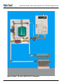
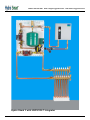
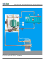
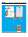
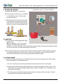
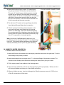
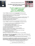
INSTALLATION MANUAL FOR THE
HSPS120LT & HSPS120Q1 INTEGRATOR
Works with the Hydro Shark 3, Hydro Smart 170 & BTH Ultra Boilers
Seamless Integration of heating source to emitters
HSPS120LT
HSPS120Q1
PHONE:
1-800-355-4945
EMAL:
[email protected]
WEB:
www.energyproducts.biz
WARNING!!
Do not plug in control cord until all fluids and
thermostat connection is finished.
DAMAGES - If unit is damaged, do not return to store. Please call 1-800-355-4945 for trouble
shooting, returns, or replacement parts.
Step 1- Mount Integrator Panel onto wall with four 1/4” x 1 - 1/2” Lg wood screws. Utilize the slots
on the top and bottom of integrator panel.
Step 2- Install Clear Y Strainer as shown in picture. Attached to strainer with a tube of sealant.
Apply thread sealant to male part of thread. Rotate strainer clockwise until tight.
Step 3- Install 3/4” supply and return lines to boiler. Use 3/4 type L copper or 3/4” oxygen barrier
PEX tubing.
Step 4- Install 1” supply and returns to emitter devices (Manifold). Use 1 “ type L copper or 1”
oxygen barrier PEX tubing.
Step 5- Introduce fluids into system and purge air out of system.
Step 6- Optional - (highly recommended) Install Backflow/Autofill device on autofill connection point
on panel. (If system fluids are reduced due to relief valve opening the autofill will replace the fluid automatically.
Step 7- Install low voltage thermostat (TH135 or TH115-AF-024T)
Step 8- Plug in cord and activate thermostat. Acknowledge the following:
A. Both circulator pumps running
B. Boiler energized and providing heat.
C. Observe gauges for performance of system (Pressure & Temperature).
For more comprehensive installation manual visit our website at:
www.hydro-smart.com
PHONE:
1-800-355-4945
EMAL:
[email protected]
Hydro Smart 170 with HSPS120LT Integrator
WEB:
www.energyproducts.biz
PHONE:
1-800-355-4945
EMAL:
[email protected]
Hydro Shark 3 with HSPS120LT Integrator
WEB:
www.energyproducts.biz
PHONE:
1-800-355-4945
EMAL:
BTH Ultra with HSPS120LT Integrator
[email protected]
WEB:
www.energyproducts.biz
PHONE:
1-800-355-4945
EMAL:
Quietside with HSPS120Q1 Integrator
[email protected]
WEB:
www.energyproducts.biz
PHONE:
1-800-355-4945
I. FILLING THE SYSTEM
A. System is assembled, it is time to fill it.
B. Fill the system until there are no air bubbles in it. Air bubbles cause circulator pumps and element failures.
EMAL:
[email protected]
WEB:
www.energyproducts.biz
OVERVIEW OF A TYPICAL SYSTEM
C. Purge the system one loop at a time. Open one loop with all of the other loops closed repeat down the manifold. Purge each loop until no air is seen in the discharge/fill tank.
II. SOLUTION
A. The solution should be polypropylene glycol and city water
NOT: RV antifreeze - it is for non moving solutions and breaks down; automotive antifreeze - it is Toxic; well water - there is a bacteria in well water that in the presence of glycol and heat can turn into a bio-film, coat elements and plug up the boiler.
B. The mixture should contain more than 20% but less than 50% pure glycol. Increased glycol percentages increases the head pressure of the system. Proper flows through the system may not be reached as a result the boiler may not work; too little glycol promotes bacteria growth.
III. ATTACH HOSES
A. Obtain 3 washing machine hoses, one 20 gallon tub for mixing, and a transfer pump 1/2 HP or larger
(not a sump-pump or a submersible pump)
1. Put one of the hoses into the mixing tub attach the other end to the intake of the fill pump.
2. Attach the second hose (red) to the discharge side of the pump and attach the other end to “A” the bottom gate valve on the lower flange of the primary circulator. The gate valve “A” should be in the open position while filling.
3. The ball valve on the lower Webstone flange should be in the Open position at this time. The ball valve handle “B” should be in line with the tubing.
PHONE:
1-800-355-4945
EMAL:
[email protected]
4. Attach the third hose (blue) to valve “C” located above
the primary circulator. Put the other end into the fill tub. This valve “C” should be open allowing water to circulate through the floor and all of the loops back to the bucket where it started. The bucket must have fluid in it at all times
while filling. As the water returns the fluid may be milky, this is air in the solution. The fluid must be circulated until all air is removed and the water runs clear.
WEB:
www.energyproducts.biz
FILLING HOSE CONNECTIONS
5. The ball valve “D” located on the upper flange should be closed during filling and Open when in operation.
6. If this is a primary/secondary system (2 pumps on the main panel) the purge valve should be in the vertical position “E” while filling. This forces the fluid through the floor, and prevents flow to the primary loop during the filling process. After the system is filled make sure that the purge valve “E” is open and in a horizontal position.
Note: If you have a Caleffi differential by-pass kit on your
manifold you need to attach the fill hose to “C” and the discharge hose to “A’. This reverses the flow and allows you to still purge each loop individually and not open the by pass while filling.
IV. DOMESTIC WATER FORCED FILL
A. Domestic water forced fill procedure
E
1. Attach the fill hose to the domestic city water supply, attach the other end to the gate valve “A” on the bottom flange of the primary circulator.
2. Attach the discharge hose to the gate valve “C” on the upper flange of the primary circulator. The other end of the discharge hose should be submerged in water prior to going into a drain.
3. Fill the system, watch for air bubbles in the discharge water.
4. Open each loop individually so the air can be purged from each loop separately. Watch your tub to see if any air bubbles are coming out of the solution while filling.
5. When no bubbles are seen, close the discharge line. When the pressure comes to 15-25 lbs, turn
off the fill valve and shut off the water.
PHONE:
1-800-355-4945
EMAL:
[email protected]
WEB:
www.energyproducts.biz
V. FINISH FILLING
A. Water has turned form milky to clear.
B. NO air bubbles are seen.
C. Close the discharge ball valve.
D. Keep pumping until pressure on the gauge is 15-20 lbs.
E. Turn off the fill valve.
F. Shut off the pump, the system should be free of air and at pressure.
VI. PRESSURE MAINTENANCE SYSTEMS FOR CLOSED LOOP SYSTEMS (Recommended)
A. Limited volume and unlimited volume
1. Use an Axiom system feeder for a pressure maintenance system that has a limited reserve.
Limits any leak to 3 gallons.
2. Household water auto fill system. This is attached to the house water supply and has unlimited
water flow. It has a pressure maintenance valve and a back flow preventer.
3. Must be either treated city water or a polypropylene glycol mix.
4. Either systems can be attached to the upper right fitting on the Flex-Pro panel for pressure maintenance.
FILLING THE SYSTEM
SYSTEM IN OPERATION