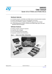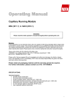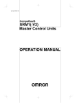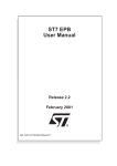
1
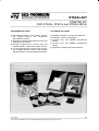
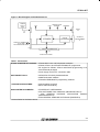
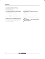
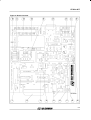
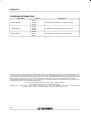
Datum 980826 PRODUKTINFORMATION HÄMTFAX 08-580 941 14 FAX ON DEMAND +46 8 580 941 14 INTERNET http://www.elfa.se TEKNISK INFORMATION 020-75 80 20 ORDERTEL 020-75 80 00 ORDERFAX 020-75 80 10 TECHNICAL INFORMATION +46 8 580 941 15 ORDERPHONE +46 8 580 941 01 ORDERFAX +46 8 580 941 11 Vi reserverar oss mot fel samt förbehåller oss rätten till ändringar utan föregående meddelande ELFA artikelnr. 73-641-02 ST622X starter kit Antal sidor: 07 ST622x-KIT STARTER KIT FOR ST620x, ST621x and ST622x MCUs HARDWARE FEATURES ■ ■ ■ ■ Immediate evaluation of all ST620x, ST621x and ST622x devices, with stand-alone demonstration routines. Simulation and debugging within the user’s real application environment. In-socket programming of all DIL OTP and EPROM ST620x, ST621x and ST622x devices. In-circuit programming of all DIL and SO OTP and EPROM ST620x, ST621x and ST622x devices directly on the user’s application board. SOFTWARE FEATURES ■ ■ ■ ■ ■ Software simulation, including I/O read/write. Assembler, Linker and Debugger. In-socket OTP and EPROM programming utilities. In-circuit OTP and EPROM programming utilities Application examples and demonstrations July 1996 This is advance information from SGS-THO MSON. Details are subject tochange without notice. 1/6 1 ST622x-KIT 1 DESCRIPTION The ST622x Starter Kit can be used for evaluation, simulation and emulation purposes. First, it can be used to demonstrate the capabilities of the ST6225. It is only necessary to connect the supply to the board and to load the demonstration software provided with the Kit into the ST62E25 sample. The same board can be used as a hardware interface to the software simulator when connected to the PC. Analog or digital values from the ST622x I/O pins can also be loaded directly to the simulator. Once the program is successfully simulated, it can be loaded in a ST62E25 or ST62E20 by using the on-board programmer (DIL packaged devices only). The application environment can be connected to the Starter Kit via the I/O connector to perform a full evaluation of the user application. In addition, an in-circuit programming facility is provided with the Kit to enable programming, via the Starter Kit board, of any ST62E25 (EPROM) or ST62T2x (OTP) already mounted in the user application board. 1.1 HARDWARE ITEMS The Kit includes 2 samples of ST62E25, 2 samples of ST62E20, an RS232 interface, a temperature control circuit, a trimmer, a set of LED and buttons, all cables plus a power supply. Pins are available for direct connection to an external user application. The board is connected to the PC via the parallel port. 1.2 SOFTWARE ITEMS The diskette provided with this kit includes an enhanced simulator including I/O read/write, assembler, linker, EPROM/OTP ST6 programming facilities and demonstration examples. 2/6 1.3 DOCUMENTATION A full set of documents is provided with the Kit including the ST622x data book, a Kit guide and the ST62/63 Software Development Tools user manual. 1.4 SYSTEM REQUIREMENT The ST622x Starter Kit communicates with a PCAT compatible Personal Computer equipped with a hard disk and a 3 1/2” diskette drive, 640k of conventional memory, one parallel Centronic compatible port and MS-DOS version 3.10 or higher. 1.5 BULLETIN BOARD SYSTEMS Software Tools upgrades, sample code and documentation are available to registered users on the SGS-THOMSON Bulletin Board Systems (BBS). These are accessible by Modem at the following numbers: – In the USA: (1) 847 517-1898 2400-14.4k baud (V22bis), 8-bits, No Parity, 1 Stop bit (8,N,1) – In Europe : Micros Technical Support Hotline (France): (+33) 76 04 93 99 9600 baud (V32) and lower, 8,N,1 Note: This product conforms with the 89/336/EEC directive; it also complies with the EN55022 emissions standard for ITE, as well as with generic 50082-1 immunity standards. The product is a Class A apparatus. In a residential environment this device may cause radioelectrical disturbances which may require that the user adopt appropriate precautions. The product is not contained in an outer casing, and cannot therefore be immune against electrostatic discharge (ESD): it should therefore only be handled at static safe work stations. ST622x-KIT Figure 1. Block Diagram of ST622x Starter Kit POWER DAC SUPPLY LEDs TEMPERATU RE CONTROL TRIMMER UNIT RS232 P2 J3 JP1 ST62E25 EPROM PROGRAMMER IN-CIRCU IT PROGRAMMING J1 PARALLEL CONNECTI ON TO PC AND SOFTWA RE SIMULATOR P1 ST622x I/O CONNECTION J2 USER APPLICATION Table 1. kit Contents ST622x STARTER KIT Hardware: – ST6225 MCU Core and Peripherals evaluation – ST620x, ST621x and ST622x EPROM/OTP programmer – DIL support for ST620x, ST621x and ST622x programming, in 16, 20 and 28 lead packages – Power supply and PC-AT connection cable SOFTWARE TOOLS: – AST6/LST6 ST6 family assembler/linker – SIMST6 simulator software – ST622xPG EPROM/OTP programming software APPLICATION ROUTINES: – Demonstration programs – Basic subroutines library ASSOCIATED DOCUMENTS: – STARTER KIT USER MANUAL – ST6 SOFTWARE TOOLS MANUAL (DBST6SOFTOST/x)* – ST62 GENERAL PURPOSE APPLICATION MANUAL (AMST62APPLST/x)* – ST62 GENERAL PURPOSE DATA BOOK (DBST6ST/5) *Contact Sales for the latest version. 3/6 ST622x-KIT 2 HARDWARE DESCRIPTION 2.1 BOARD OVERVIEW 12- IN CIRCUIT programming connector J1 PC station connector P1 (for links to simulator and programming softwares) 3- 8 Mhz crystal oscillator 4- 10 Kohms trimer including jumper W4-PA5 5- Power supply JACK connectorJ3andJP1 pads 6- Power supply LED indicator LD1 7- Heater resistor power LED indicator LD2 8- Heater resistor circuit including jumper W6TIMER 9- Thermistor circuit including jumper W5-PA4 10- ”+” and ”-” pushbuttons including jumpers W8-PB4 and W9-PB3 4/6 11- RESET pushbutton 12- Demonstration routine selector including jumpers W10 13- RS232 interface circuit and connector including jumpers W7 14- 4 LEDs Level indicator including jumpers W3 15- DIL 20-28 MCU socket 16- User’s I/O interface connector J2 17- ”ST6220” or ”ST6225” device selection jumpers W1 18- ”Programming” or ”User” operating mode selection jumpers W2 19- ST622x-KIT 10 11 12 13 14 15 16 17 18 Figure 2. Board Overview 9 8 7 6 5 4 3 2 1 VR02087B 5/6 ST622x-KIT ORDERING INFORMATION Starter Kit Device Description ST620x ST622x-KIT/220 ST621x Complete Kit for operation from 220 Vac mains ST622x ST620x ST622x-KIT/110 ST621x Complete Kit for operation from 110 Vac mains ST622x ST620x ST622x-KIT/UK ST621x Complete Kit for operation in United Kingdom ST622x Information furnished is believed to be accurate and reliable. However, SGS-THOMSO N Microelectronics assumes no responsibility for the consequences of use of such information nor for any infringement of patents or other rights of third parties which may result from its use. No license is granted by implication or otherwise under any patent or patent rights of SGS-THOMSON Microelectronics. Specification mentioned in this publication are subject to change without notice. This publication supersedes and replaces all information previously supplied. SGS-THOMSON Microelectronics products are not authorized for use as critical components in life support devices or systems without express written approval of SGS-THO MSON Microelectronics. 1996 SGS-THOM SON Microelectronics -Printed in Italy - All Rights Reserved. SGS-TH OMSON Microelectronics GROUP OF COMPANIES Australia - Brazil - Canada - China - France - Germany - Hong Kong - Italy - Japan - Korea - Malaysia - Malta - Morocco - The Netherlands Singapore - Spain - Sweden - Switzerland - Taiwan - Thailand - United Kingdom - U.S.A. 6/6