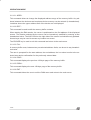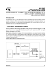
1
ST90E158-EPB EPROM PROGRAMMING BOARDS FOR ST9 MCU FAMILY MAIN FEATURES ■ Programming of the ST90158 MCUs in window EPROM or plastic OTP version. ■ PLCC84 and supported. ■ totypes or a small amounts of micro-controllers. For a mass production it’s recommended to use the appropriate gang programmer. package The ST90E158-EPB can operate in remote PC driven mode: menu driven software. S19 or intel hex file format. mode under control of a MS-DOS _ compatible computer using the standard PC parallel port. PQFP80 DESCRIPTION The ST90E158-EPB EPROM Programming Board is designed for programming a window EPROM or OTP microcontroller of the ST90158 family. The EPROM can be programmed on the ST90E158 or ST90T158 EPROM/OTP members of the ST90158 family. It is dedicated for programming pro- Object code in either INTEL HEX or MOTOROLA S19 format is read from disk files to program the target device. The menu driven software also offers VERIFY, BLANK CHECK, READ master and other utility functions. Rev. 1.0 July 1998 1/14 1 Table of Contents 1 INTRODUCTION . . . . . . . . . . . . . . . . . . . . . . . . . . . . . . . . . . . . . . . . . . . . . . . . . . . . . . . . . . . . . .3 1.1 Equipment supplied . . . . . . . . . . . . . . . . . . . . . . . . . . . . . . . . . . . . . . . . . . . . . . . . . . . . . . .3 1.2 Device installation on the socket . . . . . . . . . . . . . . . . . . . . . . . . . . . . . . . . . . . . . . . . . . . . . 3 1.3 Power supply . . . . . . . . . . . . . . . . . . . . . . . . . . . . . . . . . . . . . . . . . . . . . . . . . . . . . . . . . . . .3 2 USING PRECAUTIONS AND WORK ENVIRONMENT . . . . . . . . . . . . . . . . . . . . . . . . . . . . . . . . 4 2.1 Testers and equipment . . . . . . . . . . . . . . . . . . . . . . . . . . . . . . . . . . . . . . . . . . . . . . . . . . . .4 2.2 Work station . . . . . . . . . . . . . . . . . . . . . . . . . . . . . . . . . . . . . . . . . . . . . . . . . . . . . . . . . . . . .4 2.3 Manipulation of finish goods . . . . . . . . . . . . . . . . . . . . . . . . . . . . . . . . . . . . . . . . . . . . . . . . .4 3 OPERATION MODE . . . . . . . . . . . . . . . . . . . . . . . . . . . . . . . . . . . . . . . . . . . . . . . . . . . . . . . . . . .5 3.1 Hardware installation . . . . . . . . . . . . . . . . . . . . . . . . . . . . . . . . . . . . . . . . . . . . . . . . . . . . . .5 3.2 Software installation . . . . . . . . . . . . . . . . . . . . . . . . . . . . . . . . . . . . . . . . . . . . . . . . . . . . . . .5 3.3 Default path and file extension . . . . . . . . . . . . . . . . . . . . . . . . . . . . . . . . . . . . . . . . . . . . . . . 6 3.4 Program execution . . . . . . . . . . . . . . . . . . . . . . . . . . . . . . . . . . . . . . . . . . . . . . . . . . . . . . . .6 3.5 Selecting and exiting a command . . . . . . . . . . . . . . . . . . . . . . . . . . . . . . . . . . . . . . . . . . . . 7 3.6 Functions descriptions . . . . . . . . . . . . . . . . . . . . . . . . . . . . . . . . . . . . . . . . . . . . . . . . . . . . .7 3.6.1 TYPE : . . . . . . . . . . . . . . . . . . . . . . . . . . . . . . . . . . . . . . . . . . . . . . . . . . . . . . . . . . . .7 3.6.2 DEV : . . . . . . . . . . . . . . . . . . . . . . . . . . . . . . . . . . . . . . . . . . . . . . . . . . . . . . . . . . . . .7 3.6.3 LPT : . . . . . . . . . . . . . . . . . . . . . . . . . . . . . . . . . . . . . . . . . . . . . . . . . . . . . . . . . . . . .7 3.6.4 LOAD : . . . . . . . . . . . . . . . . . . . . . . . . . . . . . . . . . . . . . . . . . . . . . . . . . . . . . . . . . . .8 3.6.5 RAM : . . . . . . . . . . . . . . . . . . . . . . . . . . . . . . . . . . . . . . . . . . . . . . . . . . . . . . . . . . . .8 3.6.6 FILE : . . . . . . . . . . . . . . . . . . . . . . . . . . . . . . . . . . . . . . . . . . . . . . . . . . . . . . . . . . . . .8 3.6.7 PROG : . . . . . . . . . . . . . . . . . . . . . . . . . . . . . . . . . . . . . . . . . . . . . . . . . . . . . . . . . . .8 3.6.8 VERIF : . . . . . . . . . . . . . . . . . . . . . . . . . . . . . . . . . . . . . . . . . . . . . . . . . . . . . . . . . . .9 3.6.9 BLANK : . . . . . . . . . . . . . . . . . . . . . . . . . . . . . . . . . . . . . . . . . . . . . . . . . . . . . . . . . .9 3.6.10 READ : . . . . . . . . . . . . . . . . . . . . . . . . . . . . . . . . . . . . . . . . . . . . . . . . . . . . . . . . . . .9 3.6.11 SPACE : . . . . . . . . . . . . . . . . . . . . . . . . . . . . . . . . . . . . . . . . . . . . . . . . . . . . . . . . . .9 3.6.12 EXIT : . . . . . . . . . . . . . . . . . . . . . . . . . . . . . . . . . . . . . . . . . . . . . . . . . . . . . . . . . . . .9 3.6.13 RAM edit menu . . . . . . . . . . . . . . . . . . . . . . . . . . . . . . . . . . . . . . . . . . . . . . . . . . . . .9 3.6.13.1ADDR : . . . . . . . . . . . . . . . . . . . . . . . . . . . . . . . . . . . . . . . . . . . . . . . . . . . .10 3.6.13.2EDIT : . . . . . . . . . . . . . . . . . . . . . . . . . . . . . . . . . . . . . . . . . . . . . . . . . . . . .10 3.6.13.3FILL : . . . . . . . . . . . . . . . . . . . . . . . . . . . . . . . . . . . . . . . . . . . . . . . . . . . . .10 3.6.13.4PGUP : . . . . . . . . . . . . . . . . . . . . . . . . . . . . . . . . . . . . . . . . . . . . . . . . . . . .10 3.6.13.5PGDN : . . . . . . . . . . . . . . . . . . . . . . . . . . . . . . . . . . . . . . . . . . . . . . . . . . . .10 3.6.13.6EXIT : . . . . . . . . . . . . . . . . . . . . . . . . . . . . . . . . . . . . . . . . . . . . . . . . . . . . .10 4 ANNEXES . . . . . . . . . . . . . . . . . . . . . . . . . . . . . . . . . . . . . . . . . . . . . . . . . . . . . . . . . . . . . . . . . 11 4.1 ANNEX I: Errors messages . . . . . . . . . . . . . . . . . . . . . . . . . . . . . . . . . . . . . . . . . . . . . . . . 11 4.2 ANNEX II: EPB90158.DEV syntax . . . . . . . . . . . . . . . . . . . . . . . . . . . . . . . . . . . . . . . . . . . 12 14 2/14 2 INTRODUCTION 1 INTRODUCTION 1.1 Equipment supplied - 1 ST90E158-EPB programming board 1 Power supply 1 communication cable 1 3”1/2 floppy disk containing the software. 1.2 Device installation on the socket Put the device onto the null insertion force socket with the erasure window on the top and the pin 1 matching the mark (white point) on board. Take care not to make a mistake when positioning the device to avoid possible damages to both the board and the device. 1.3 Power supply The board can be supplied from the integrated power supply provided with the board, or from an external +15V DC / 0.5A power supply. When using an external power supply, take care of the polarities marked nearby the two points connector. 3/14 USING PRECAUTIONS AND WORK ENVIRONMENT 2 USING PRECAUTIONS AND WORK ENVIRONMENT 2.1 Testers and equipment This product conforms to the 89/336/EEC directive with reference to the EN55022 emissions standard for ITEs and EN50082-1 generic immunity standard. This product is a class A appartus. In a residential environment this device may cause radioelectrical disturbances which may require the user to adopt appropriate precautions. This product is not into an outer casing and is not therefore protected against the electrostatics discharges (ESD). Therefore all tester, equipment and tools used at any production step or for any manipulation of semi-conductor devices must have its shield connected to GROUND. 2.2 Work station The antistatic work station is composed of: - A conductive table top, made of steel or clean aluminium or covered by an antistatic surface (superficial resistivity equal or superior to 0.5 Megohm/cm2), grounded through a ground cable (conductive cable from protected equipment to ground isolated through a 1 MΩ resistor placed in series). - An antistatic floor covering grounded through a conductive ground cable (with serial resistor between 0.9 and 1.5 MΩ). 2.3 Manipulation of finish goods Manipulation of finish goods must be made at a grounded work station (see 2.1 and 2.2). It is mandatory to wear (either on wrist or ankle) an antistatic bracelet, connected to the antistatic floor covering or to the grounded equipment. It is mandatory to wear antistatic gloves or finger coats. Nylon clothing is prohibited during manipulation of parts. The work station must be free of any non antistatic plastic objects. The wearing of the antistatic bracelet must be controlled every day 4/14 OPERATION MODE 3 OPERATION MODE 3.1 Hardware installation The following steps must be performed. – Power off the computer. – Using the interface cable delivered with the board, connect the PC computer parallel interface port (LPT1 or LPT2) to connector P1 of the ST90E158 programmer. Do not connect the cable to a serial interface of the PC: damages to the board may occur. – Power the programmer using the power supply adaptor delivered with your programming board package: it is adapted to the mains voltage and the mains outlet shape in use in your country. – Power on the computer. Notes: 1) The supplied interface cable has been tested in order to operate properly on most PC’s; please do not use another cable, especially if it is longer that the one provided by STMicroelectronics: the board may not operate properly. 2) The cable should be connected directly to the DB-25 female connector of the PC parallel port; this connector is similar to the one present on the programming board; please, do not insert any additional cables nor switchboxes between the PC and the board: a malfunction of the board may result. 3) If a dongle (hardware key required by some PC software) is already connected on the PC parallel port, it should not interfere with the programming board. However, if you notice a malfunction of the board, please remove the dongle(s) and restart the above sequence. 3.2 Software installation First of all, it is strongly recommended to copy the contents of the original source disk supplied with the ST90E158-EPB on another disk, and to keep the original disk in a safe place. Since the contents of the floppy disk are not copy protected, you just have to type the following command: COPY A:*.* C: (assuming the floppy disk is inserted in the A: drive). It is possible to work directly on a floppy disk but it is strongly recommended to install the software package on your PC’s hard disk in order to operate at the maximum speed. Then, the following operations should be performed: – Insert the supplied disk in the relevant disk drive (Usually drive A). – Create a working directory on your hard disk (e.g. type: MD C:\EPB90158) – Type the following command: COPY A:*.* C:\EPB90158 The software package provided with the board includes the following files: 5/14 OPERATION MODE – EPB90158.BAT: This is a batch file which calls the different graphics utilities and the main program. This is the file to launch to start the EPROM Programming Software. – PGM90158.EXE: This the main program. – EPB90158.DEV: This file contains the list of the existing ST90158 family members including their names, and programming address ranges. – EPB90158.LBR: This file contains the different screens used by the main program. – BEG.COM, AFFICHE.COM, END.COM are utility files for graphics screens. All these files must be located in the same directory (e.g. C:\EPB90158). 3.3 Default path and file extension The default path for all the software is the path from which the program was called. If the desired file is in another directory the user has to type the entire access path. The default file extension is .HEX and the default file type supported is the MOTOROLA format. Nevertheless the INTEL HEX format is also usable when reading a file. 3.4 Program execution Under MS-DOS prompt, type the command: EPB90158 <cr> Note: In this document, <cr> stands for the ”Return” key on the computer keyboard. If you want to execute the program from MS-Windows_, be careful to specify EPB90158.BAT as the executable file, in order to launch the graphics environment properly. A title screen is displayed. Press any key to enter the TYPE menu. Select the device type and press <cr>. You can now select the desired function. The different functions available are described in the following pages. Note: MS-DOS_ and Windows_ are trademarks of Microsoft corporation. 6/14 OPERATION MODE 3.5 Selecting and exiting a command For selecting a command, the user can either move the cursor (inverted video bar) to the desired function with the SPACE BAR or an arrow key and press <cr> or type the uppercase letter corresponding to the desired command in the top screen menu. Each time the cursor is moving, a message briefly describing the selected function appears at the left bottom of screen. Error messages are displayed at the bottom of the screen. All the possible error messages are described at the end of the document. Any function can be aborted by pressing the ESCAPE key. 3.6 Functions descriptions 3.6.1 TYPE : This function allows the user to select the type of device he wants to program. The selection is done by moving the inverted video bar until the desired device name is reached and by pressing <cr>. Different informations are selected at the same time : – Memory mapping. – Version of microcontroller (OTP / EPROM / ROM). (See ANNEX II for use of devices other than those listed by ”TYPE”.) These informations have been read by the software from the file EPB90158.DEV during the startup phase of the software. (See file syntax in annex 2). These setup data are set by STMicroelectronics for each ST90158 family member and should not be changed by the customers. Without these data or if they are corrupted the software will be unable to operate properly. Notes: 1) The name of the selected device is displayed at the bottom right corner of the screen. 2) Until this function is complete, all the other commands cannot be reached. 3.6.2 DEV : This function allows the user to display and verify the specifications of the previously selected device. Pressing any key exits the function. 3.6.3 LPT : This function allows the user to change the selected parallel communication port. The port is selected by moving the cursor to the desired port and pressing <cr> to validate the selection. The default selection is port LPT1. 7/14 OPERATION MODE 3.6.4 LOAD : This function loads the data from the selected file into the PC memory buffer. The user is prompted to enter the desired filename. If no path or file extension are provided the default settings will be used. Data will be read from the file until either the memory buffer is full, or end of file is reached. The FILE checksum is then displayed as well as the DEVICE checksum which is the reflection of the device selected. If the file doesn’t exist, or is not found in the specified directory, a message will appear on screen and the user will be prompted to enter a new filename. If any problems are encountered during file loading, an error message will be displayed at the bottom of the screen. (See error message description in annex 1 for more details). 3.6.5 RAM : This command allows the user, by the mean of a specific menu, to examine and modify the contents of the memory buffer. The RAM function operation will be detailed later (see page of the present manual, RAM menu section). 3.6.6 FILE : This function writes the data in the memory buffer onto the disk using the supplied filename. This file is stored using an INTEL HEX format. Should a file with the same name already exist, the user will be prompted to confirm overwriting of the previous file. If any problems are encountered during command execution, an error message will be displayed at the bottom of the screen. (See error message description in annex 1 for more details). 3.6.7 PROG : The selected memory SPACE of the selected device will be programmed using the data stored in the memory buffer. The user can modify the values from start and end addresses of the memory area to be programmed; otherwise the default values corresponding to the selected memory will be used. The device memory will be programmed using a specific programming algorithm defined by STMicroelectronics. After programming each byte, the content of the device will be verified against the memory buffer byte to confirm the successful programming. After a correct verify operation a success message will appear. If a programming error is encountered, a ’failure’ message will appear on screen indicating the failing byte address. 8/14 OPERATION MODE If any other problem is encountered (device not present in the socket, defective device,...), an error message is displayed at the bottom of screen. (See error message description in annex 1 for more details). 3.6.8 VERIF : This function compares the contents of the selected memory SPACE of the device against the data contained in the memory buffer. The verify procedure is interrupted if any data mismatch is detected, and an error message is displayed indicating the error address location. (See error message description in annex 1 for more details). 3.6.9 BLANK : This command performs a blank checking of the device EPROM memory. The command is available only if an EPROM-type device (ST90E158 or ST90T158) and the EPROM memory space are currently selected. A ’fail’ or ’success’ message will indicate whether the device EPROM is effectively blank or not. A blank EPROM byte reads as FF hex. (See error message description in annex 1 for more details). 3.6.10 READ : This function reads the content of the selected memory SPACE of the device and stores its content into the memory buffer. After the read operation is complete, the checksum of the read data will be displayed. If any problem is encountered during reading, an error message will appear on the screen. 3.6.11 SPACE : This function allows to select the device memory SPACE on which the PROG, VERIF, BLANK and READ commands will operate: actually only EPROM/OTP space on ST90158 devices. The selected space is marked ’ON’ in the bottom right corner of the screen. 3.6.12 EXIT : This command allows the user to exit the program and return to the operating system. 3.6.13 RAM edit menu This menu is accessed through the RAM function from the main menu. It allows to examine and modify the memory buffer contents where the programming data are stored. The screen displays a 128-byte range starting from the lowest memory address of the selected memory area (as defined in the file EPB90158.DEV). 9/14 OPERATION MODE 3.6.13.1 ADDR : This command allows to change the displayed address range of the memory buffer. Any address between the minimum and maximum device memory can be entered (in hexadecimal). Locations above the upper address limit of the device are not displayed. 3.6.13.2 EDIT : This command is used to edit the memory buffer contents. When starting the Edit session, the cursor is positioned on the first address of the displayed screen. The location selected by the cursor can be interactively modified by entering a new hexadecimal value. The ASCII field on the right side of the screen is simultaneously updated. Arrows keys may be used to access any location on screen. The ESCAPE key is used to exit this command and return to the main menu. 3.6.13.3 FILL : A memory buffer area, between two pre-selected address limits, can be set to any hexadecimal value. The user is prompted for the start address, the end address, the hex value to write to the selected area and a confirmation for the previously entered data. 3.6.13.4 PGUP : This command displays the previous 128-byte page of the memory buffer. 3.6.13.5 PGDN : This command displays the next 128-byte page of the memory buffer. 3.6.13.6 EXIT : This command allows the user to exit the RAM menu and return to the main menu. 10/14 ANNEXES 4 ANNEXES 4.1 ANNEX I: Errors messages Device not yet selected This message means that you attempt to execute a command before selecting a device. This is required to set different parameters like the maximum EPROM addresses. File not yet loaded This message appears when the commands which operate on data in PC memory buffer are called before loading data from an hexadecimal file. No hexadecimal file The selected file doesn’t match either the INTEL HEX or the MOTOROLA S19 format. Checksum error The data contained in the hexadecimal file are wrong. You must verify the file content. File contents exceeds memory size The data file content exceeds the device MCU memory capacity or doesn’t match the available memory areas. Address > memory size The specified address is greater than the maximum EPROM. Start address > End address The specified starting address is greater than the end address. Access to non available memory range Access to a memory range which is not in the right memory space of the device as defined in the file EPB90158.DEV. Writing disk error This error could be caused by a disk full situation. Attempt to write to a write protected disk The disk is write-protected. Attempt to access to an unknown unit The specified destination drive is unknown by DOS system. Drive not ready No disk is present or detected in the drive. Drive error General failure during disk operation. 11/14 ANNEXES Setup file not found During startup phase, the remote software didn’t find the setup data file in the working directory. Invalid setup file content The content of the setup file is corrupted. Port LPT1 is not installed No parallel port is installed on your computer. Refer to your computer user manual. Port LPT2 is not installed Only one or no parallel port is installed on your computer. Refer to your computer user manual. Target chip not present or defective Unsuccessful attempt to read or write to a device. Check if the programmer is properly connected and supplied, if the device is inserted properly into the zero insertion force socket and if the device is not defective. Blank check not performed on EEPROM Attempt to use the Blank check function when the EEPROM memory space is selected. Device fails at address xxxxH During a Verify command or a verification performed at the end of a Programming command a mismatch has been found between the byte read from the device and the corresponding byte in the buffer. During a Blank check of the EPROM, this message indicates that a byte is not read as FF hex (erased state). 4.2 ANNEX II: EPB90158.DEV syntax This file specifies the device names and the available EPROM and EEPROM memory areas; it has the following syntax: – For a ST90E158 EPROM version: Name of device: ST90E158 Memory header: <EEPROM addresses> Min. and Max. memory address in hex: 0000 0000 Memory header: <EPROM addresses> Min. and Max. memory address in hex: 0000 F7FF Min. and Max. address of first area: 0000 F7FF Last area: Device separator 12/14 ANNEXES – For a ST90T158 OTP version: Name of device: ST90T158 Memory header: <EEPROM addresses> Min. and Max. memory address in hex: 0000 0000 Memory header: <OTP addresses> Min. and Max. memory address in hex: 0000 F7BF Min. and Max. address of first area: 0000 F7BF Last area: Device separator: * Contents of EPB90158.DEV: ST90E158 <EEPROM addresses> 0000 0000 <EPROM addresses> 0000 F7FF 0000 F7FF * ST90T158 <EEPROM addresses> 0000 0000 <OTP addresses> 0000 F7BF 0000 F7BF * Be very careful to respect the following points if you ever modify the file contents: – The different headers must not be modified. – The different memory areas must be in increasing order. – The min and max addresses of these areas must not exceed the min and max memory addresses of the device. 13/14 ANNEXES Notes: Information furnished is believed to be accurate and reliable. However, STMicroelectronics assumes no responsibility for the consequences of use of such information nor for any infringement of patents or other rights of third parties which may result from its use. No license is granted by implication or otherwise under any patent or patent rights of STMicroelectronics. Specifications mentioned in this publicatio n are subject to change without notice. This publication supersedes and replaces all information previously supplied. STMicroelectronics products are not authorized for use as critical components in life support devices or systems without the express written approval of STMicroelectronics. The ST logo is a registered trademark of STMicroelectronics. 1998 STMicroelectronics - All Rights Reserved. Purchase of I2C Components by STMicroelectronics conveys a license under the Philips I 2C Patent. Rights to use these components in an I2C system is granted provided that the system conforms to the I2C Standard Specification as defined by Philips. STMicroelectronics Group of Companies Australia - Brazil - Canada - China - France - Germany - Italy - Japan - Korea - Malaysia - Malta - Mexico - Morocco - The Netherlands Singapore - Spain - Sweden - Switzerland - Taiwan - Thailand - United Kingdom - U.S.A. 14/14