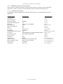
1
ATX23/24 Printer User Manual File: UMATX403.pdf
ATX 23/24
Printer Series
User Manual
-1- (V1.03 Dated 9/2/03)
ATX23/24 Printer User Manual File: UMATX403.pdf
Table of Contents:
1
ADMINISTRATIVE INFORMATION ..................................................................................................... 8
1.1
How To Contact Us............................................................................................................................... 8
1.2
Limited Product Warranty..................................................................................................................... 8
1.2.1
Warranty Terms ............................................................................................................................ 8
1.2.2
Warranty Procedure....................................................................................................................... 8
1.3
FCC Notification .................................................................................................................................. 9
1.3.1
Regulatory Compliance ................................................................................................................. 9
1.3.1.1 Regulatory Compliance Caution ................................................................................................ 9
1.4
2
Trademarks........................................................................................................................................... 9
ATX 23/24 OVERVIEW .......................................................................................................................... 10
2.1
Introduction........................................................................................................................................ 10
2.2
Product Description............................................................................................................................ 10
2.3
MODEL NUMBER INFORMATION ................................................................................................... 11
2.3.1
ATX 23/24 System Model Number.............................................................................................. 11
2.3.2
ATX 23/24 Separate Component Model Numbers ....................................................................... 11
3
PREPARATION FOR USE...................................................................................................................... 12
3.1
Unpacking and Inspection................................................................................................................... 12
3.2
Installation Location........................................................................................................................... 12
3.3
Power Connection............................................................................................................................... 12
3.4
Data I/O Interface Connection - Parallel ............................................................................................ 12
3.5
Paper Supply ...................................................................................................................................... 12
3.6
Paper Loading .................................................................................................................................... 12
3.7
Test Print ............................................................................................................................................ 13
3.8
Printer Set-up Confirmation................................................................................................................ 13
3.8.1
Configuration PCB DIP Switch Settings...................................................................................... 13
3.8.2
EEPROM Settings....................................................................................................................... 13
3.9
Printer Driver Installation .................................................................................................................. 13
3.9.1
WindowsTM 95, 98, and NT – Installing the Driver...................................................................... 13
3.9.2
Selecting the Driver..................................................................................................................... 13
3.10
4
Configuring the Printer Port ............................................................................................................... 13
OPERATOR CONTROLS and INDICATORS....................................................................................... 14
4.1
Rear I/O Panel.................................................................................................................................... 14
4.2
Switch and Display Panel ................................................................................................................... 14
4.3
Panel LED Indicators ......................................................................................................................... 14
4.3.1
Power/Paper ................................................................................................................................ 14
4.3.2
Ready.......................................................................................................................................... 14
4.3.3
Attn/Err ...................................................................................................................................... 14
4.4
Panel Switches.................................................................................................................................... 15
-2- (V1.03 Dated 9/2/03)
ATX23/24 Printer User Manual File: UMATX403.pdf
4.5
Panel Switch Operations..................................................................................................................... 15
4.5.1
Offline Operations....................................................................................................................... 15
4.5.1.1 Offline Switch Operations Table.............................................................................................. 15
4.5.2
Power-On Operations .................................................................................................................. 16
4.5.2.1 Power-On Operations Table..................................................................................................... 16
4.5.2.2 Printer System Information and Reports .................................................................................. 16
4.5.2.3 System Status Report ............................................................................................................... 16
4.5.2.4 System Information Help Report.............................................................................................. 18
4.5.2.5 Diagnostic Menu ..................................................................................................................... 20
4.5.2.6 Change TOF Configuration ..................................................................................................... 20
4.5.2.7 EEPROM Change Menu.......................................................................................................... 20
4.5.2.8 Re-Program Flash Memory...................................................................................................... 20
4.5.2.9 Hex Dump Diagnostic Mode.................................................................................................... 20
4.5.2.10
Printhead Cleaning Diagnostic Mode................................................................................... 20
5
PRINTER PROGRAMABLE CONFIGURATION SETTINGS ............................................................ 21
5.1
Overview............................................................................................................................................. 21
5.1.1
Interconnect & Configuration PCB.............................................................................................. 21
5.1.2
Paper Output Delivery Option Detection...................................................................................... 21
5.1.3
Special Customization ................................................................................................................. 21
5.1.4
EEPROM Parameter Storage Memory......................................................................................... 22
5.1.4.1 EEPROM Factory Defaults ...................................................................................................... 22
6
Printer Status Information ....................................................................................................................... 23
6.1
ATX 23/24 Printer Status Overview..................................................................................................... 23
6.1.1
Operator Status............................................................................................................................ 23
6.1.2
Parallel Interface Compatibility Mode Status ............................................................................... 23
6.1.3
Parallel Interface IEEE-1284 Reverse Channel Status.................................................................. 23
6.1.3.1 Printer Status Utility Program.................................................................................................. 23
6.1.3.2 Reverse Channel Status Types ................................................................................................. 23
6.1.3.2.1 IEEE-1284 ID String Data ................................................................................................ 24
6.1.3.2.1.1 ID String Command ................................................................................................... 24
6.1.3.2.1.2 ID String Format ........................................................................................................ 24
6.1.3.2.1.3 ID String Content....................................................................................................... 24
6.1.3.2.2 Detailed Status Data.......................................................................................................... 24
6.1.3.2.2.1 Detailed Status Data Types......................................................................................... 24
6.1.3.2.2.2 Selection of Detailed Status Information..................................................................... 24
6.1.3.2.2.3 Detailed Status String Organization ........................................................................... 24
6.1.3.2.2.3.1 Detailed Status String Schematic Format ............................................................. 25
6.1.3.2.2.3.2 Detailed Status Selection Commands ................................................................... 25
6.1.3.2.2.3.3 Detailed Status Data Fields .................................................................................. 25
6.1.3.2.2.3.3.1 Short Status: Bit Flag Status Data ................................................................. 25
6.1.3.2.2.3.3.2 Detailed Status Data Notes ............................................................................ 26
6.1.3.2.2.3.3.2.1 Flags: ..................................................................................................... 26
6.1.3.2.2.3.3.2.2 System Not Ready: ................................................................................. 26
6.1.3.2.2.3.3.2.3 Detailed Status Data Fields..................................................................... 26
6.1.3.2.2.3.3.2.4 Detailed Status Field Notes..................................................................... 26
6.1.3.2.2.3.3.2.5 Detailed Status Field Descriptions .......................................................... 26
6.1.3.2.2.4 Reporting Document Length....................................................................................... 27
6.1.3.2.2.5 Detailed Status Reading Protocol................................................................................ 27
6.1.3.2.2.6 Status and Spooler Management................................................................................. 27
6.1.3.2.2.7 Detailed Status Field 01 - Error Code List .................................................................. 28
7
DATA INTERFACE AND AUXILIARY I/O .......................................................................................... 30
7.1
IEEE-1284 Parallel Interface ............................................................................................................. 30
-3- (V1.03 Dated 9/2/03)
ATX23/24 Printer User Manual File: UMATX403.pdf
7.1.1
7.1.2
7.1.3
7.1.4
Parallel Port Signaling ................................................................................................................ 30
Parallel Interface Cable Schematic .............................................................................................. 30
Parallel Interface Cable Quality................................................................................................... 30
Parallel Interface Pin-out Table ................................................................................................... 30
7.2
USB Interface ..................................................................................................................................... 31
7.2.1
USB Interface Cable/Driver ......................................................................................................... 31
7.3
Auxiliary I/O Connector ..................................................................................................................... 31
7.3.1
Auxiliary I/O Pin-out................................................................................................................... 31
8
PAPER HANDLING OPTIONS .............................................................................................................. 32
8.1
Paper Output Delivery Options........................................................................................................... 32
8.1.1
Transport-Presenter ..................................................................................................................... 32
8.1.1.1 Perforated Paper Stock............................................................................................................. 32
8.1.1.2 Blocked Output Control ........................................................................................................... 32
8.1.1.3 Ticket Taken Status and Control.............................................................................................. 32
8.1.1.4 Loop Storage Chamber ............................................................................................................ 32
8.1.1.5 Dispose Storage Chamber ........................................................................................................ 32
8.1.1.5.1 Host Monitoring of Disposed Tickets ................................................................................ 32
8.1.1.6 Programmable Transport Presenter Controls............................................................................ 32
8.1.1.6.1 Transport Presenter without Dispose Storage Space .......................................................... 32
8.1.1.6.1.1 Blocked Output Non-Dispose Options ........................................................................ 32
8.1.1.6.1.2 Ticket Not Taken Non-Dispose Options...................................................................... 33
8.1.1.6.2 Transport Presenter with Dispose Storage Space ............................................................... 33
8.1.1.6.2.1 Blocked Output Dispose Options ................................................................................ 33
8.1.1.6.2.2 Ticket Not Taken Dispose Options ............................................................................. 33
8.1.2
Jam Resistant Output................................................................................................................... 33
8.1.2.1 Full Cut Operation................................................................................................................... 33
8.1.2.2 Partial Cut Ticket Presenter ..................................................................................................... 33
8.2
Paper Input Delivery Options ............................................................................................................. 34
8.2.1
Formula for Calculating Paper Roll Capacity............................................................................... 34
8.2.2
Internal 6” Diameter Paper Roll Holder....................................................................................... 34
8.2.3
External 10” Diameter Paper Roll Holder .................................................................................... 34
8.2.3.1 External 10” Diameter Paper Roll Holder Drawing.................................................................. 34
8.2.3.2 Externally Located Paper Design Considerations ..................................................................... 35
8.2.3.2.1 External Roll Holder Paper Path Recommendations Drawing............................................ 35
8.2.4
Low Paper Monitoring................................................................................................................. 36
8.2.4.1 Low Paper Host Status Information.......................................................................................... 36
8.2.4.2 Printer Reactions to the Low Paper Condition.......................................................................... 36
9
PAPER INFORMATION......................................................................................................................... 37
9.1
Paper Specifications ........................................................................................................................... 37
9.1.1
Paper Width ................................................................................................................................ 37
9.1.2
Roll Size...................................................................................................................................... 37
9.1.3
Recommended Papers.................................................................................................................. 37
9.1.4
Print Activation Energy............................................................................................................... 37
9.1.4.1 Other Print Activation Energy Controls ................................................................................... 37
9.1.5
Roll Paper Curl Considerations ................................................................................................... 37
9.1.6
Paper Form Type......................................................................................................................... 37
9.1.6.1 Continuous Forms ................................................................................................................... 37
9.1.6.2 Registration Mark Forms......................................................................................................... 37
9.1.7
Paper Pre-Printing Information ................................................................................................... 38
9.1.7.1 Pre-Printed Paper: Bottom Side Restrictions ............................................................................ 38
9.1.7.2 Pre-Printed Paper: Top Side..................................................................................................... 38
9.1.7.3 Registration Mark Location: Bottom Side ................................................................................ 38
-4- (V1.03 Dated 9/2/03)
ATX23/24 Printer User Manual File: UMATX403.pdf
9.2
Paper Form Type Recognition ............................................................................................................ 38
9.2.1
Printer Recognition of Paper Form Type...................................................................................... 38
9.2.2
Host PC Recognition of Paper Form Type and Size...................................................................... 39
9.3
Paper Form Size Determination.......................................................................................................... 39
9.3.1
Printer Determination of Form Size............................................................................................. 39
9.3.1.1 Continuous Forms ................................................................................................................... 39
9.3.1.2 Registration Marked Forms ..................................................................................................... 39
9.3.1.2.1 Autosize Measurement of Form Length............................................................................. 39
9.3.1.2.2 Stored Form Length .......................................................................................................... 39
9.3.1.2.2.1 Default Form Size ...................................................................................................... 39
9.3.1.2.2.2 Entering a Fixed Form Size into EEPROM Memory................................................... 39
9.3.1.2.2.3 Autosize Measurement and Save to EEPROM ............................................................ 40
9.3.2
Host Determination of Form Size ................................................................................................ 40
10
10.1
EEPROM PARAMETER STORAGE MEMORY.............................................................................. 41
EEPROM Parameter Memory Overview ............................................................................................. 41
10.2 EEPROM Change Menu Entry............................................................................................................ 41
10.2.1 EEPROM Change Menu Operation ............................................................................................. 41
10.2.2 Active and Inactive Menu Line.................................................................................................... 41
10.3 EEPROM Menu #1 Printout................................................................................................................ 42
10.3.1 EEPROM Menu #1 Parameters Definitions ................................................................................. 42
10.3.1.1
Print Intensity...................................................................................................................... 42
10.3.1.2
Increase Print Intensity ........................................................................................................ 42
10.3.1.3
Decrease Print Intensity ....................................................................................................... 42
10.3.1.4
Print Energy Table............................................................................................................... 42
10.3.1.5
Print Cycle Offtime.............................................................................................................. 42
10.3.1.6
Print Control Misc. .............................................................................................................. 42
10.3.1.7
Print Area ............................................................................................................................ 42
10.3.1.8
IPS Clamp Limit.................................................................................................................. 42
10.3.1.9
Interface Misc. ..................................................................................................................... 42
10.3.1.10 Buzzer ................................................................................................................................. 43
10.4 EEPROM Menu #2 Printout................................................................................................................ 43
10.4.1 EEPROM Menu #2 Parameters ................................................................................................... 43
10.4.1.1
Low Paper............................................................................................................................ 43
10.4.1.2
Paper Backup....................................................................................................................... 43
10.4.1.3
Change Stored Size: Forms Len 10’s, 1’s, 0.1’s; 0.01’s........................................................ 43
10.4.1.4
Form Stored Size ................................................................................................................. 43
10.4.1.5
Form TOF............................................................................................................................ 43
10.4.1.6
Form Misc. .......................................................................................................................... 43
10.4.1.7
Average Power..................................................................................................................... 44
10.4.1.8
Print Mode........................................................................................................................... 44
10.4.1.9
Status Pointer....................................................................................................................... 44
10.4.1.10 Output Jam Control ............................................................................................................. 44
10.4.1.11 Ticket Not Taken Dispose Control ....................................................................................... 44
10.4.1.12 Purge Spooler Control.......................................................................................................... 44
10.4.1.13 Cutter Mode......................................................................................................................... 44
10.5
11
Restoring Factory Default Settings ..................................................................................................... 44
ERROR CODES ................................................................................................................................... 45
11.1 Annunciation ...................................................................................................................................... 45
11.1.1 Sequence Length ......................................................................................................................... 45
11.1.2 Weighted Positions...................................................................................................................... 45
11.1.3 Counting ..................................................................................................................................... 45
-5- (V1.03 Dated 9/2/03)
ATX23/24 Printer User Manual File: UMATX403.pdf
11.1.4
Example...................................................................................................................................... 45
11.2 Error Code Table................................................................................................................................ 46
11.2.1 Error Code Table Notes ............................................................................................................... 46
11.2.2 Error Code Table Information ..................................................................................................... 46
11.2.3 Error Code Computation ............................................................................................................. 46
12
12.1
DIAGNOSTICS and MAINTENANCE ............................................................................................... 47
Diagnostic Entry................................................................................................................................. 47
12.2 Diagnostic Sub Menu.......................................................................................................................... 47
12.2.1 Special Functions ........................................................................................................................ 47
12.2.2 Burn-in and Cut Tests ................................................................................................................. 48
12.3 Hex Dump Mode ................................................................................................................................. 48
12.3.1 Data Rate Measurement Test ....................................................................................................... 48
12.4 Periodic Maintenance......................................................................................................................... 48
12.4.1 Paper/Registration Mark Sensor Maintenance ............................................................................. 48
12.4.2 Printhead Cleaning...................................................................................................................... 48
12.4.2.1
Printhead Cleaning Diagnostic Tool .................................................................................... 48
13
POWER SUPPLY INFORMATION.................................................................................................... 49
13.1
Power supply D.C. Output Cable ........................................................................................................ 49
13.2
Power Management ............................................................................................................................ 49
13.3 Power Supply Requirements................................................................................................................ 49
13.3.1 Power Supply Additional Requirements....................................................................................... 49
14
PROCEDURE FOR RE-PROGRAMMING FLASH MEMORY ...................................................... 50
14.1
General............................................................................................................................................... 50
14.2
Requirements ...................................................................................................................................... 50
14.3 Flash Re-Programming Process.......................................................................................................... 50
14.3.1 Entering the Flash Load Mode..................................................................................................... 50
14.3.2 Flash Data Loading ..................................................................................................................... 50
14.3.3 Flash Loading Completion .......................................................................................................... 51
14.3.4 Flash Loading Time .................................................................................................................... 51
14.3.5 Warning...................................................................................................................................... 51
15
APPLICATION PROGRAMMERS INFORMATION ....................................................................... 52
15.1 Overview - Printer Commands ............................................................................................................ 52
15.1.1 Status String Selection Commands .............................................................................................. 52
15.1.2 Document Length Command....................................................................................................... 52
15.1.3 Document Re-Present .................................................................................................................. 52
15.2
Operating System Characteristics ....................................................................................................... 52
15.3 Host Application PC Characteristics .................................................................................................. 53
15.3.1 System Clock Rate....................................................................................................................... 53
15.3.2 High Speed Parallel Port.............................................................................................................. 53
15.3.3 Detailed Printer Status................................................................................................................. 53
15.4 Printer Driver Characteristics ............................................................................................................ 53
15.4.1 Printer Driver Properties Box ...................................................................................................... 53
15.4.1.1
Page Size Tab ...................................................................................................................... 53
15.4.1.2
Graphics Tab ....................................................................................................................... 53
-6- (V1.03 Dated 9/2/03)
ATX23/24 Printer User Manual File: UMATX403.pdf
15.4.1.3
Device Options Tab ............................................................................................................. 53
15.5 Printing from WindowsTM High Level Application Programs................................................................ 54
15.5.1 Understanding Margins............................................................................................................... 54
15.5.2 Most WindowsTM High Level Applications ................................................................................... 54
15.5.3 MS-Word and other Template-based Applications....................................................................... 54
16
SPECIFICATIONS............................................................................................................................... 55
17
APPENDIX ........................................................................................................................................... 56
17.1
IEEE 1284 Parallel A-B Cable Schematic........................................................................................... 56
17.2 ATX23/24 Mechanical Drawings......................................................................................................... 57
17.2.1 Mechanical Detail Drawing: ATX23/24 Printer with Transport Presenter ................................... 57
17.2.2 Mechanical Detail Drawing: ATX23/24 Printer with Protected Output........................................ 57
17.2.3 Power Supply Module (Shown with AC Line Cord)..................................................................... 58
-7- (V1.03 Dated 9/2/03)
ATX23/24 Printer User Manual File: UMATX403.pdf
1 ADMINISTRATIVE INFORMATION
1.1 How To Contact Us.
PRACTICAL AUTOMATION INC
The Alinabal Group of Companies
45 Woodmont Road
P.O. Box 3028
Milford, CT 06460
VOICE: (203) 882-5640
FAX: (203) 882-5648
EMAIL:[email protected]
INTERNET: http://www.practicalautomation.com
1.2 Limited Product Warranty
1.2.1 Warranty Terms
Practical Automation, Inc. warrants each new ATX 23/24 series printer to be free from defects in materials and
workmanship to the original purchaser. Our responsibility is limited to repair or replacement of the printer and/or
accessory or part thereof at our option for a period of six months from the date of shipment.
This limited warranty does not extend to any defect, malfunction or failure caused by or resulting from improper
service, packing, maintenance or repair, abuse, neglect, accident, or any other cause beyond the control of Practical
Automation, Inc. or to any product whose serial number has been removed, altered, replaced or rendered illegible.
Except and to extent provided herein, Practical Automation, Inc. makes no warranty, either express or implied,
including any warranty of merchantability or fitness for a particular purpose.
Practical Automation, Inc. shall not be liable to the purchaser or to any other person or firm for any specified or
consequential damages of any kind which result from the use or misuse by any person or loss of profits or product
resulting from any defect or malfunction or failure of this product.
No person, agent, distributor, service facility or company is authorized to change, modify or amend the terms of
this limited warranty in any manner or fashion whatsoever.
1.2.2 Warranty Procedure
If you cannot resolve your equipment problem, notify Practical Automation, giving the model and serial number of
your equipment. Describe your problem in detail.
Upon receipt of this information, Practical Automation will send you service information if the trouble is easily
corrected. If the trouble requires factory service, we will so advise and provide written return authorization. Loaner
printers can usually (subject to availability) be shipped within 24 hours during the workweek by Practical
Automation. Customers are required to pay all shipping charges.
Refer also to the Warranty Terms and Packaging and Shipping instructions before returning any equipment.
-8- (V1.03 Dated 9/2/03)
ATX23/24 Printer User Manual File: UMATX403.pdf
1.3 FCC Notification
FOR USERS IN THE UNITED STATES
WARNING:
Changes or modifications to this unit not expressly approved by the party responsible for compliance could void the
user's authority to operate the equipment.
Note:
This equipment has been tested and found to comply with the limits for a Class A digital device, pursuant to Part
15 of the FCC rules. These limits are designated to provide reasonable protection against harmful interference
when the equipment is operated in a commercial environment. This equipment generates, uses, and can radiate
radio frequency energy and, if not installed and used in accordance with the instruction manual, may cause
harmful interference to radio communications. Operation of this equipment in a residential area is likely to cause
harmful interference in which case the user will be required to correct the interference at his own expense.
Shielded cables must be used with this unit to insure compliance with the Class A FCC limits.
FOR USERS IN CANADA
---------------------------------------------------------------------------------------------------------------------------------This Class [A] digital apparatus meets all requirements of the Canadian Interference-Causing Equipment
Regulations.
-------------------------------------------------------------------------------------------------------------------------------Cet appareil numerique de la classe [A] respecte toutes les exigences du Reglement sur le material brouilleur du
Canada.
--------------------------------------------------------------------------------------------------------------------------------
1.3.1 Regulatory Compliance
Safety:
UL 1950, 3rd Edition
CSA C22.2 No. 950-95
CENELEC EN 60950: 1992
EMI/EMC:
FCC Part 15 Class A
CENELEC EN 50082-1 1992 and EN 55022 Class B
1.3.1.1
Regulatory Compliance Caution
In order to insure EMI/EMC compliance, all Input and Output cables must be shielded.
1.4 Trademarks
All references to WindowsTM products are trademarks of Microsoft. All other trademarks are property of the
manufacturers, and used for reference only.
-9- (V1.03 Dated 9/2/03)
ATX23/24 Printer User Manual File: UMATX403.pdf
2 ATX 23/24 OVERVIEW
2.1 Introduction
This instruction manual provides information for the ATX 23/24 printer and its associated support options. It
provides installation, operational, programming, systems applications notes and maintenance information.
2.2 Product Description
The ATX 23/24 printer uses direct thermal imaging to print on a narrow format 3.34” or 4.48” paper. It can print
on roll stock paper, with or without registration marks. Designed for use in applications where fast printing is
required, the ATX 23/24 has features and options structured to support unattended operation in a kiosk or similar
environment. These features include output isolation devices providing a range of functions from simple jam
protection to complete document isolation during the print cycle (loop presenter). Document separation is by an
integrated cutter. Paper supply can be from a printer-mounted roll holder for 6” diameter paper roll, or an
externally mounted, large capacity, 10” diameter roll holder. Either roll holder can be outfitted with an optical low
paper sensor.
The ATX 23/24 is connected to the system using an IEEE-1284 Parallel Interface cable (or a USB serial add-on adapter
cable). The interface cable is an off-the-shelf IEEE-1284 A-B cable. The ATX 23/24 makes its extensive status information
accessible over the interface, using IEEE-1284 reverse nibble communications. The status provides the OEM host system
with information such as: low paper, out of paper, ticket taken, error conditions, etc.
An external 24V-power module provides the power for ATX 23/24. This single 24V operation makes for easier integration
into an OEM system power distribution scheme. An additional benefit is a power management scheme to budget the
printer’s operation to a modest 55W average power allocation (Refer to section 13.2)
The ATX 23/24 operates under the WindowsTM operating system utilizing a WYSIWYG driver supplied by Practical
Automation. Visit our website, http://www.practicalautomation.com for the latest Drivers. Combined with a raster
organized printer controller, this flexible driver will print any text or graphic image, at 203 DPI resolution, from any
WindowsTM application.
The printer, control electronics, ticket presenter, and on-chassis paper supply, are integrated into a self-contained module.
The power supply is a separate module connected to the printer through a 6’ shielded cable and circular DIN connector.
This modular packaging scheme is extremely convenient and suitable for mounting into the application OEM system.
-10- (V1.03 Dated 9/2/03)
ATX23/24 Printer User Manual File: UMATX403.pdf
2.3 MODEL NUMBER INFORMATION
2.3.1 ATX 23/24 System Model Number
ATX 2 X ____ - ____
|
|
|
|
BN PW PS
PH
____
|
FC
____
|
PS
____ - ____
|
|
I
CN
BN
Base Number:
ATX 2X
PW
Printer Width
3
4
=
=
3.34” Print Mechanism
4.48” Print Mechanism
PS
Power Supply Options:
N
S
E
=
=
=
None
Standard (55W Supply w/U.S. line cord) (17.2.3)
European (55W Supply w/o line cord) (17.2.3)
PH
Paper Handling:
C
L
T
=
=
=
Cutter (with Output Protection Chamber) (17.2.1)
Loop Transport-Presenter (with Cutter) (17.2.2)
Tearbar (with Output Protection Chamber) (Future)
FC
Forms Control
1
2
=
=
Continuous roll stock paper
Registration marked paper on a Roll (9.1.7.3)
PS
Paper Supply
1
=
2
=
Guides for external paper supply (10” Diameter) with low paper
sensor (8.2.3.1)
Internal roll holder (6” Diameter) with low paper sensor
P
=
Parallel
S
=
IEEE-1284 to USB Serial Interface (7.2)
(Win 2K only) (Cable supplied as an additional item)
##
=
Two digit number for special configurations
I
CN
Interface
Customization Number
2.3.2 ATX 23/24 Separate Component Model Numbers
Model Number
Description
PS55-14
Universal input (100-240 VAC, 50-60 Hz) Power Supply 24VDC @55W supplied with
US 115V line cord. (17.2.3)
PS55-14E
Universal input (100-240 VAC, 50-60 Hz) Power Supply 24VDC @55W supplied
without a line cord. (17.2.3)
ATX24-10RH
Large (10” diameter) capacity paper roll holder, adjustable for 3.34” or 4.48” wide paper
stock. Used for ATX23 or ATX24 printers.
ATX24-10RHLP
Large (10” diameter) capacity paper roll holder with low paper sensor. Includes
a 6’auxiliary cable (ATX-AC8). Is adjustable for 3.34”or 4.48” wide paper stock. Used
for ATX23 or ATX24 printers. (8.2.3.1)
ATX-AC8
Auxiliary cable. Shielded, 6’long, 8 conductors, with MINIDIN-8 connector.
ATX-PC36
IEEE-1284 A-B Parallel interface cable 6’ long.
ATX-USBIA
USB to IEEE-1284 Interface Adapter Cable (Win 2K only)
-11- (V1.03 Dated 9/2/03)
ATX23/24 Printer User Manual File: UMATX403.pdf
3 PREPARATION FOR USE
3.1 Unpacking and Inspection
-a- Inspect the shipping container for any signs of damage. If any damage is noted, contact freight
carrier and file a claim with them.
-b-Carefully unpack the printer system.
-c- Inspect the printer system carefully.
-d- Check the received items to the packing list. If any discrepancies are noted, contact our Customer
Service Department.
-e-Save the packing material for reuse in shipment of the printer system.
3.2 Installation Location
The ATX 23/24 printer system is designed for OEM applications. It is the responsibility of the OEM system
designer to insure that the printer is installed in a manner to insure reliable operation. The printer’s environment
should be clean and ventilated appropriately. Refer to the installation drawings in the appendix.
3.3 Power Connection
Refer to section 4.1 for a drawing of the printer’s rear panel.
-a- Insure that the power switch, on the rear panel of the printer is in the off position.
-b- Connect the DC power output cable from the power supply to the power input connector on the rear
panel of the printer.
-c- Connect the AC line cord to the IEC entrance connector on the power supply.
-d-Connect the AC line cord to the wall power outlet.
3.4 Data I/O Interface Connection - Parallel
The ATX 23/24 printer requires a shielded IEEE-1284 A-B parallel cable to connect to a WindowsTM compatible
PC. Refer to section 4.1 for a drawing of the printer’s rear panel. The cable model and part number is (ATX-PC36)
and (A09-71140).
-a- Connect the 36 pin connector end of the cable to the parallel input cable on the rear of the printer.
-b- Connect the 25 pin connector end of the cable to the parallel output port of the PC.
3.5 Paper Supply
The paper supply for the ATX 23/24 can be mounted on the printer chassis, or on an external paper roll holder.
The on chassis paper holder will hold rolls up to 6” in diameter. The optional external paper holder can hold rolls
up to 10” in diameter. For all paper supplies the thermally active side of the paper needs to be facing up (inner
surface of the roll). Registration marks must be on the opposite side from the printing side. For an external paper
supply, the roll holder must be positioned to provide a smooth, well-aligned, path to the printer’s paper entry
guides. (Refer to section 8.2.3) for information pertaining to the paper supply.
3.6 Paper Loading
The printer will automatically load the paper onto the drive roller of the printer. For auto-loading, the printhead
lever, located on front left side of the printer mechanism, must be closed (in the fully downward position). After
applying power to the printer a long beep will be sounded indicating the printer is ready to accept paper. Feed the
paper into the rear paper guide until the paper sensor detects it. This will trigger the paper loading operation and
pull the paper into the loaded position.
-12- (V1.03 Dated 9/2/03)
ATX23/24 Printer User Manual File: UMATX403.pdf
3.7 Test Print
Once the paper has been loaded successfully a test ticket should be printed to insure that everything is operating
properly. Pressing the SELECT/F0 switch will place the printer offline; the READY LED will go out. Then by
pressing the TEST/F1 switch a test page will be printed. Refer to section 4.5 for detailed information on these
switch operations.
3.8 Printer Set-up Confirmation
It is recommended that the System Status Report be printed immediately after installation (power up while pressing
F0). Review the settings and confirm that they match your requirements. Refer to section 4.5.2.3.
3.8.1 Configuration PCB DIP Switch Settings
The printer is configured, at the factory, to support the installed options: printer width, form type, and paper cutter.
To verify these configuration DIP Switch settings, refer to section 5.1.1.
3.8.2 EEPROM Settings
If any settings on the Systems Status Report are not set in accordance with the intended operation of the printer,
(Refer to section 10.2) and follow the procedure to change these settings in the EEPROM.
3.9 Printer Driver Installation
Before installing the driver, copy all the files on the driver diskette to a new folder on your hard drive called ATX
23/24. Then follow the instructions for your operating system.
3.9.1 WindowsTM 95, 98, and NT – Installing the Driver
The ATX 23/24 WindowsTM driver installs following the standard Install Printer wizard. Put the ATX 23/24 driver
disk in your floppy drive. From the Start Menu, select Settings, Printers, and then double-click on Add Printer.
Following the instructions, select “Have Disk…”, and confirm that the drive letter is the same as the drive that
holds the disk. A list of printer drivers will be displayed. Select the driver that matches the size of your ATX
23/24 printer. Select OK or Yes to the remaining questions. The ATX 23/24 driver is now installed and any
WindowsTM application can now print using the ATX 23/24 printer.
3.9.2 Selecting the Driver
The printer system is now ready for operation. Configure your application to use the correct ATX23/24 printer
driver. Select paper size and margins. The printer should now be matched to your application and you may print.
If you are not using a WindowsTM based application, refer to the appropriate OEM system manual for operation of
the printer under that application software.
3.10 Configuring the Printer Port
For best performance, the printer port should be configured to run in ECP mode with DMA. Other modes are
significantly slower and will result in slower printing. On most computers, configuring the printer port must be
done before WindowsTM is loaded. From the WindowsTM Start Menu, select Shut Down, and Restart, and OK. As
the computer restarts, there will be the manufacturers splash screen, which should indicate which key will enter the
System BIOS Set-Up mode (usually F1). Find the Printer Port Mode selection (it may be on a second page, or
under “Peripherals”), and select ECP mode with DMA, if available. If your PC, does not have the ECP mode
option, leave the setting as it was. Save and Exit and continue the boot-up process. Most PCs have this feature.
Refer to your PC Manual as required.
-13- (V1.03 Dated 9/2/03)
ATX23/24 Printer User Manual File: UMATX403.pdf
4 OPERATOR CONTROLS and INDICATORS
4.1 Rear I/O Panel
These located on this rear printer panel are: the power switch, power input connector, auxiliary I/O cable
connector and the parallel data interface connector. The power switch in combination with holding one or more of
the switch and display panel switches provides entry into special set-up menus or diagnostic programs.
The Aux I/O socket is for connecting a low-paper sensor from an external paper supply.
Power
Input
Aux I/O
4.2 Switch and Display Panel
The switch and display panel provides the operator with an interface to the printer.
The display LEDs and buzzer are used to output relevant printer operational status
and warnings. The switches provide a means to control the various printed output
menus and test functions.
4.3 Panel LED Indicators
4.3.1
Power/Paper
This green LED indicator provides the following printer status information:
-1- Sanity indication/Normal display = very short OFF blink approx. every 14 sec.
-2- Presence of DC power
= ON or Flashing when power is on.
-3- Out of Paper
= rapid ON/OFF 50% duty cycle flashing when out of
paper.
-4- Low Paper
= slow ON/OFF 50% duty cycle flashing when paper is low.
-5- Diagnostic testing modes
= 10% ON and 90% OFF when in diagnostic mode.
4.3.2
Ready
This green LED indicator provides the following printer status information:
-1- System readiness for operation
= ON system is ready to accept data; OFF not ready.
-2- Data flow
= During the receipt of data, the LED will blink,
following the state of the Busy signal.
-3- Reverse channel status
= While not printing, during an IEEE-1284 reverse
channel status event, this LED will blink, following
the state of the Busy signal.
4.3.3
Attn/Err
This amber LED indicator, in combination with the buzzer, is a general-purpose annunciator for the operator. It
provides the following printer status information:
-1- Switch press annunciation
= short flash/beep for each switch pressed
-2- System warnings
= an attention flash/beep to alert the operator to load
paper, etc.
-3- System error codes
= a repeating sequential series of coded flash/beep
signals.
-4- Normal display
= OFF
-14- (V1.03 Dated 9/2/03)
ATX23/24 Printer User Manual File: UMATX403.pdf
4.4 Panel Switches
There are four momentary push button switches on the user panel. These are used for a variety of manual
interactions with the printer. Some of these are printing a test ticket, entering data into the printer parameter
memory (EEPROM), and selecting miscellaneous diagnostic operations.
The switches are labeled:
SELECT/F0
TEST/F1
LINE FEED/F2
FORM FEED/F3
On/Off line Select
Test print
Line feed
Form feed
/
/
/
/
Function 0
Function 1
Function 2
Function 3
4.5 Panel Switch Operations
The switch and display panel switches are used for two modes of operation. These are offline and power-on
operations.
4.5.1 Offline Operations
When the printer is operating normally, and on-line, pressing the [SELECT/F0] switch manually takes the printer
to an offline state. NOTE: As a reminder to the operator the A/E LED and buzzer will produce a single flash/beep
approximately every 14 seconds. When the system is offline the switches operate in accordance with the Offline
Switch Operations Table shown below.
4.5.1.1
Offline Switch Operations Table
Switch
SELECT / F0
TEST / F1
Operation/Function
Offline / Online toggle
Prints a test ticket.
LINE FEED / F2
FORM FEED / F3
Advances the paper approximately 0.1”
Advances the paper one form length.
F0 and F1
Causes the cutter to actuate.
-15- (V1.03 Dated 9/2/03)
Notes
Offline enables functions below.
Alternately prints one of two
simple ASCII test tickets
Simple paper movement.
Length depends on the printer
setup and form type.
Only when a cutter is installed.
The switches must be released
together.
ATX23/24 Printer User Manual File: UMATX403.pdf
4.5.2 Power-On Operations
These functions provide an additional level of diagnostic support tools. These functions are provided for service or
technical support personnel.
4.5.2.1 Power-On Operations Table
For this mode, one or more switches are pressed, and held, while applying power to the printer. The switch is held
until a flash/beep (A/E LED/ buzzer) occurs. The lists of power-on operations are detailed below. Refer to section
4.5.2.4 for System Information Help Report, which outlines each menu, listed below.
Switch
SELECT / F0
TEST / F1
LINE FEED / F2
FORM FEED / F3
F0 and F1
F0 and F2
F2 and F3
Operation/Function
Print system status report.
Notes
If held longer, prints help menus.
(Refer to sec. 4.5.2.4 “System
Info Help Report”).
Enter diagnostics menu entry.
Refer to section 12.1
Change the TOF configuration (Hold 5 Sec) Refer to section 4.5.2.6
Enter EEPROM change menu
Refer to section 10.2.1
Re-program Flash Memory.
Refer to section 14.3
Printhead cleaning.
Refer to section 4.5.2.10
Hex Dump Diagnostic Mode
Refer to section 12.3
4.5.2.2
Printer System Information and Reports
Printer system status information is available through a number of printed reports. These are the System Status
Report, System Help Report, EEPROM Interactive Parameter Change Menu, and Diagnostic Support Menus.
4.5.2.3
System Status Report
This is a printed report, which contains much of the operational or stored parameter information for the system. It
includes: firmware version numbers, diagnostic pass/fail results, interface configuration status, print intensity
control levels, miscellaneous system control parameters and operational data. This report is printed by continuously
holding the [F0] switch while turning on the power.
-16- (V1.03 Dated 9/2/03)
ATX23/24 Printer User Manual File: UMATX403.pdf
*********************************************************
*
SYSTEM STATUS REPORT
*
*********************************************************
*Model:
ATX-24
*Firmware:
V1.09 (09/05/01)
*Diagnostics:
Pass/Fail
RAM
PASS
EEPROM
PASS
FLASH
PASS
FPGA/ASIC
PASS
SYS/MPU
PASS
CONFIG.
PASS
PRINTHEAD
PASS
VOLTAGE
PASS
*Interface:
TYPE
PARALLEL
MISC
N/A
*Configuration:
FORM TYPE
CONTINUOUS
OUTPUT TYPE
CUTTER & TRANSPORT
PRINT DPI
203
MISC
N/A
*EEPROM Data:
Print Control
INTENSITY
6
[ENERGY TABLE]
0
PRINT CYCLE OFFTIME
NORMAL
PRT CNTL MISC
N/A
PRINT AREA
4.10 Centered
[IPS CLAMP LIMIT]
NONE
System Control
[LOW PAPER]
STATUS Only
STORED SIZE
6.00
[TOF]
SET BY CONFIG STRAP
[MISC]
USE STORED SIZE (FIXED)
[BUZZER]
ON
[PAPER BACKUP]
ENABLED
POWER: AVE
55W
PRINT MODE
TEXT
[STATUS POINTER]
SHORT
[JAM ERROR CNTL]
STOP ON 1ST OUTPUT JAM
[TKT NOT TAKEN CNTL] DISPOSE AFTER 15 SEC
[PURGE SPOOLER CNTL] ENABLED
[CUTTER Mode]
FULL CUT
*Operational Data
PHTEMP
31C
PAPERSEN
3.33
LOWPAPERSEN
0.00
PHVOLTAGE
23.82
SYSVOLTAGE
23.82
EXSEN1
3.49
EXSEN2
3.72
SYSCS
2.49
PHCS
4.27
SERDETS
2.48
PHOSW
4.99
Sensor Calibration
Thresh = 153
POR = 682
INTERNAL STATUS
6296
= 0000 5AAA, 0010 6CB7, 0000 014C, 0001 8063, 0000 0569,
> 41, 6B, B4, 23, 98, 2B, DA, AB, 51, 07, EB, 0B,
To print help menu, continue to hold F0
-17- (V1.03 Dated 9/2/03)
ATX23/24 Printer User Manual File: UMATX403.pdf
4.5.2.4
System Information Help Report
The report above has a second part. If the switch [F0] switch is held after the first part has completed printing, the
system information help report will also be printed. This report is a collection of menus (which are printed during
the associated operating modes) and general help for other printer information such as error codes, etc.
**************************************************************
*
OFFLINE SW. HELP
**************************************************************
F0/SEL = ON/OFFLINE Toggle
F1/TST = Print TEST ticket
F2/LF
= Line FEED Paper
F3/FF
= FORM FEED Paper
F0 & F1 = CUT PAPER
NOTE: A warning BEEP/FLASH will occur every
15 sec when in the off-line condition.
*
**************************************************************
*
POR SWITCH HELP
*
**************************************************************
Apply power to unit while holding:
F0
= SYSTEM STATUS
F1
= DIAGNOSTICS
F2
= CHANGE TOF CONFIGURATION (Hold 5 sec)
F3
= EEPROM MENU
F0 & F1 = RE-PROGRAM FLASH MEMORY
F0 & F2 = PRINTHEAD CLEANING (F0/F1=Forward; F2/F3=Reverse)
F2 & F3 = HEX DUMP MODE (-or- for Data Rate Test
after entry, press: F0 then F1 then F0)
**************************************************************
*
DIAGNOSTIC HELP
**************************************************************
After entering this DIAGNOSTIC menu from POR
press and release:
F0 = SPECIAL Functions
F1 = BURN-IN test
F2 = CUT test
F3 = Not used
**************************************************************
*
SPECIAL FUNCTION/SETUP MENU
**************************************************************
Press switch for special function
F0 = Autosize value & fixed ==> EEPROM (hold 5 sec)
F1 = Reset EEPROM to Factory defaults (hold 5 sec)
F2 = PRINTHEAD ADJUSTMENT
F3 = Not used
*
*
**************************************************************
*
EEPROM ENTRY HELP
*
**************************************************************
Turn off power to printer. Press and hold F3 while turning on power. Continue
to hold F3 until a beep is heard (and flash of the A/E LED). Release F3 and wait
for a second beep/flash. Press F3 twice quickly, holding it on the second press
until printing starts.
-18- (V1.03 Dated 9/2/03)
ATX23/24 Printer User Manual File: UMATX403.pdf
***********************************************
*
EEPROM HELP
***********************************************
F0
= MOVE cursor (>) UP
F1
= MOVE cursor (>) DOWN
F2
= CHANGE selection at cursor
F3
= ENTER Next MENU level
POWER OFF = EXIT EEPROM Change MENU
*
PRINTOUT of the parameter menu occurs
approximately 1 second after pressing any switch.
By pressing F0 or F1 several times quickly and counting
the beeps the cursor can be moved several positions before
the next printout. Pressing F2 at the counted target will
cause a change of the selection. This technique permits
changes to be entered quickly without printing after each
switch press.
**********************************************
*
ERRORS HELP
**********************************************
Long flash/beep = 1
Short flash/beep = 0
Repeated binary beep/flash sequence (1,2,4,8 etc).
[#]=Sequence Length
Error Codes:
[5]
1 = MPU/SYS
2 = RAM
3 = EEPROM
4 = FLASH
5 = CHAR GEN
6 = IMAGE RAM
7 = A2D
8 = FPGA/ASIC
9 = VOLTAGE
10= PH THERMISTOR
11= PH DATA
12= PH RESISTOR
13= CUTTER INITIALIZATION
14= CONFIGURATION
15= MISC
[4]
1 = PAPER
2 = CUTTER
3 = TRANSPORT
4 = OUTPUT
5 = REGISTRATION
6 = HEAD LEVER OPEN
7 = OUT OF PAPER
[3]
1 = TICKET NOT TAKEN (beep disabled)
2 = TICKET NOT PRESENTED (beep disabled)
-19- (V1.03 Dated 9/2/03)
*
ATX23/24 Printer User Manual File: UMATX403.pdf
4.5.2.5 Diagnostic Menu
These functions are used by the factory during the manufacture or servicing of the printer. This menu is entered by
continuously holding the [F1] switch while turning on the power. (Refer to section 12.2 for diagnostic sub menu).
4.5.2.6 Change TOF Configuration
The [F2] switch is used to force a change to the printer configuration, which is normally determined by the DIP
Switch settings. By pressing the [F2] switch at power on and additionally holding it for 5 seconds the TOF
configuration will be set opposite to the one currently in force. For example, if the printer had the DIP Switch
configuration of a continuous form (roll) printer it would be forced to a registration mark configuration (preprinted or fixed size forms). (Refer to section 10.4.1.5 for other information).
4.5.2.7 EEPROM Change Menu
This menu is used to provide a method for modifying the stored printer operating parameters, that are saved in
nonvolatile EEPROM memory. Holding the [F3] switch while turning on the power enters this menu. To protect
against an inadvertent changing of stored parameter data, a special sequence using [F3] is needed following the
initial [F3] entry. Refer to the “EEPROM ENTRY HELP MENU” portion of the system help report displayed in
section 4.5.2.4 for this switch sequence. The EEPROM change menu, once entered, has instructions for changing
stored values. The EEPROM parameter change menu has two levels (an additional F3 switch press accesses the
next level). Note: Some of the parameters cannot be changed. They are reserved for future firmware updates.
(Refer to section 10 for additional information on the EEPROM stored parameter data).
4.5.2.8
Re-Program Flash Memory
This function permits the operator to change the operational firmware of the printer. This operation is NOT a
normal operator function. Technical personnel responsible for the programming or maintenance of the printer
system should only use it. This mode is entered by continuously holding the [F0 and F1] switches while turning on
the power. (Refer to section 14.3 for additional information).
4.5.2.9 Hex Dump Diagnostic Mode
This function provides a method for determining if the data is being sent over the data interface properly.
Technical personnel responsible for the programming or maintenance of the printer system generally use it. This
mode is entered by continuously holding the [F2 and F3] switches while turning on the power. Refer to section
12.3 for additional information.
4.5.2.10 Printhead Cleaning Diagnostic Mode
This function provides a method for using the paper advance motor to drive a cleaning card under the printhead, as
part of normal printer maintenance. This mode is entered by continuously holding the [F0 and F2] switches, while
turning on the power. (Refer to section 12.4.2 for maintenance information).
-20- (V1.03 Dated 9/2/03)
ATX23/24 Printer User Manual File: UMATX403.pdf
5 PRINTER PROGRAMABLE CONFIGURATION SETTINGS
5.1 Overview
The ATX23/24 printer has programmable or configuration features permitting it to be customized to almost any
printing task. This programmability resides in four areas: Interconnect & Configuration PCB, the EEPROM
nonvolatile parameter storage memory, paper output delivery option detection and special factory customizations.
5.1.1 Interconnect & Configuration PCB
This printed circuit board is mounted to side of the mechanism. It serves the dual purpose of: -1- being a collection
point for the printer mechanism’s wire harnesses and -2- a DIP switch settable configuration memory. The DIP
switch settings identify the printer’s paper width, the type of paper expected, continuous or registration marked,
roll stock paper, and the presence of a cutter. These setting are made at the factory. They are not normally changed
in the field. They are listed here for reference.
Switch #
DIP-1
DIP-2
DIP-3
DIP-4
DIP-5
DIP-6
DIP SWITCH POSITION
ON
OFF
Not Used - No Function
Not Used - No Function
Not Used - No Function
Not Used - No Function
Enable ATX23 printer
Disable ATX23 printer
Enable ATX24 printer
Disable ATX23 printer
Continuous form
Registration marked
Enable Cutter
Disable Cutter (not used - Future)
Notes
(Reserved - Future)
(Reserved - Future)
(3.38”)
(4.48”)
Switch is don’t care
5.1.2 Paper Output Delivery Option Detection
The type of output delivery option, attached to the printer, is automatically detected. A jumper strap present on the
anti-jam sensor PCB is the detection flag. This strap, when detected, tells the printer to support the anti-jam output
function. When this strap is not detected the transport-presenter function is supported.
5.1.3 Special Customization
Special customizations to the printer firmware, EEPROM settings, mechanical options, etc. can be accommodated,
for customers with special application needs, if the order volume is sufficiently large. Please contact the factory’s
customer service department.
-21- (V1.03 Dated 9/2/03)
ATX23/24 Printer User Manual File: UMATX403.pdf
5.1.4 EEPROM Parameter Storage Memory
This memory device holds the parameters, which customize the printer’s operation to specific application
requirements. ( Refer to section 10.2 for details making changes to the data stored in this device).
5.1.4.1 EEPROM Factory Defaults
The EEPROM is typically shipped with the following default settings. These setting handle most printer
applications.
Parameter Name
Default Setting
Section Reference(s)
Print Intensity:
Print Energy Table:
Print Cycle Offtime:
Print Control Miscellaneous:
Print Area:
IPS Clamp Limit:
Interface Miscellaneous:
Buzzer:
Low Paper:
Paper Backup:
Form Stored (or Measured) Size:
Form TOF:
Form Miscellaneous:
Power: Average
Print Mode:
Status Pointer:
Jam Error Control:
Ticket Not Taken Control:
Purge_ Spooler:
Cutter Mode
6
0
NORMAL
N/A
2.84 (or 4.10) CENTERED
NONE
N/A
ON
STATUS Only
ENABLED
6.00
DETERMINED BY CONFIGURATION STRAP
USE STORED FIXED SIZE
55
TEXT
SHORT
STOP ON 1ST TP OUTPUT JAM
EJECT AT NEXT TICKET
ENABLED
FULL CUT
9.1.4
9.1.4.1
9.1.4.1
9.1.4.1
10.3.1.7
10.3.1.8; 15.3.2
10.3.1.9
10.3.1.10
8.2.4; 10.4.1.1
10.4.1.2
9.3; 10.4.1.4; 6.1.3.2.2.4
10.4.1.5; 9.1.6
10.4.1.6
10.4.1.7
10.4.1.8
6.1.3.2.2.2; 10.4.1.9
8.1.1.6.1.1; 10.4.1.10
8.1.1.6.1.2; 10.4.1.11
6.1.3.2.2.6; 10.4.1.12
8.1.2; 10.4.1.13
-22- (V1.03 Dated 9/2/03)
ATX23/24 Printer User Manual File: UMATX403.pdf
6 Printer Status Information
6.1 ATX 23/24 Printer Status Overview
The ATX 23/24 printer has a wide range of status information available to suit any application environment. There
are three types of status: Operator, Parallel Interface Compatibility Mode and Parallel Interface
IEEE-1284 Reverse Channel Status. Depending on the requirements of the application the operator status, in
combination with the parallel status, may be all that is required. For other applications the detailed information
available by the parallel reverse channel status may be needed. Most of the information below addresses the
Parallel Interface IEEE-1284 Reverse Channel Status.
6.1.1 Operator Status
Operator status is that which is displayed on the printer’s switch and display panel LEDs (refer to section 4.2).
6.1.2 Parallel Interface Compatibility Mode Status
The Parallel Interface Compatibility Mode status is commonly known as the Centronics status. This status has been
part of the parallel interface since its inception. The parallel interface has several signals, which provide a top-level
view of the printer’s status. These are Busy; PError; Select, nFault. Collectively they convey if the printer is ready
for data, has paper and does not have a detected fault. In many applications this level of status is sufficient. The
WindowsTM Print Manager will report these types of errors.
6.1.3 Parallel Interface IEEE-1284 Reverse Channel Status
Parallel Interface IEEE-1284 Reverse Channel Status is a method of reading status data from the parallel interface,
as defined by the IEEE-1284 standard. The status data available via this channel includes all the data noted above
as well as additional detailed information. This detailed status information is required for the printer system
management for certain unattended applications.
6.1.3.1
Printer Status Utility Program
A utility program, that demonstrates the detailed printer status functions, is available to Practical Automation’s
customers from our customer service department. This utility is provided with source code to assist the
programmer tasked with creating the status interface for the host application. The utility program is offered on an
“as is” basis to be used as reference only. The relevant WindowsTM API calls are demonstrated and significant
insight into the techniques of this process are documented. The status function is a port driver function. The
WindowsTM programming structure does not permit the printer driver to contain these port driver functions.
6.1.3.2 Reverse Channel Status Types
There are two types of status information returned to the host:
-1- IEEE 1284 ID String data
-2- Detailed Status Data.
The ID string data is configured to meet the requirements of the IEEE specifications for that information. The
detailed status is a unique configuration of status information specific to the ATX 23/24 printer.
-23- (V1.03 Dated 9/2/03)
ATX23/24 Printer User Manual File: UMATX403.pdf
6.1.3.2.1
IEEE-1284 ID String Data
This string is returned to the meet the IEEE-1284 protocol.
6.1.3.2.1.1 ID String Command
This command is part of the extensibility request protocol, executed during IEEE-1284 the channel negotiation
phase. The extensibility request value of 0x04 is sent to the printer to determine if it can return the ID string using
nibble reverse channel mode.
6.1.3.2.1.2 ID String Format
String Length MSB; String Length LSB; String Byte #1...; String Byte #n
6.1.3.2.1.3 ID String Content
An example of the string format with typical data is shown below.
MANUFACTURER:
Practical Automation, Inc.
COMMAND SET:
PARL V1.0
MODEL:
ATX-23 (or 24)
FIRMWARE VERSION: V1.XX.xxxb (mm/dd/yy)
6.1.3.2.2
Detailed Status Data
This status data provides information on the printer's internal operating conditions, error codes, firmware version
number, etc. The amount of information available is more than a typical application will require. Also, it has been
organized for future extensibility. This excess of information provides for user flexibility. The application engineer
can select the relevant information as required. Typically, using the status organized, as bit flag information is
sufficient for most applications. All detailed status data is returned via reverse channel, nibble mode,
communications over the parallel interface.
6.1.3.2.2.1 Detailed Status Data Types
The available status data information is organized into groups. These groups are further subdivided into fields. A
selected group may have one or more data fields. The status groups are organized as follows:
Status Group Title
Data Description
Data Fields
Short Status
Normal Status
Extended Status
Addressed Status
Complete Status
Bit Flag
00
Bit Flag; Last Error
00 ; 01
Bit Flag; Last Error; FW Version 00 ; 01 ; 05
Selected By Field
Any
All Defined Status Fields
00 - 05
Notes
Factory Default
Future: New fields will be added as
they are defined.
6.1.3.2.2.2 Selection of Detailed Status Information
The default selection for the detailed status data returned, is determined by a value stored in the parameter
EEPROM memory (refer to section 10.4.1.9). Under normal conditions, and in the absence of an alternate selection
having been made, this status group string will be returned during a reverse channel read operation. A forward
Compatibility mode command is provided for making alternate selections. Also, if the forward channel is Busy
when a status read occurs the Complete Status string will always be returned, independent of the selection
EEPROM parameter or an alternate selection. This permits the recovery of any data by parsing of this string
regardless of the readiness of the forward channel.
6.1.3.2.2.3
Detailed Status String Organization
All status data is returned as a string. The string is identified by one of the status groups listed above. The status
string is organized to permit identification and parsing. The first byte of all status strings is the group identification
code (ASCII). Also, before each data field is a two byte field identification number (ASCII). If the field is defined
as a variable length field, then a two-byte length count (ASCII) will follow the field number.
-24- (V1.03 Dated 9/2/03)
ATX23/24 Printer User Manual File: UMATX403.pdf
6.1.3.2.2.3.1
Detailed Status String Schematic Format
Status String Schematic Format:
Status Type
String Format
Short
Normal
Extended
Address
Complete
=
=
=
=
=
Where:
Group ID
Field ID
Variable Length Count
Status Data Byte
6.1.3.2.2.3.2
S00_ _
N00_ _01_ _ _
E00_ _ 01_ _ _05##_ _ _ _ _ _ _ _ _ _ _
A04_ _
C00_ _ 01_ _ _02_ _ _ _ _ _ _ _03_ _ _ 04_ _05##_ _ _ _ _ _ _ _~
~ If future fields are defined (by updated firmware) they will be
appended to this string.
=
=
=
=
S;N;E;A;C
00 ; 01 ; 02 ; 03 ; 04 ; 05
##
_
Detailed Status Selection Commands
Several commands, which are sent in forward Compatibility mode, permit the alternate selection of status data
groups or fields. The selected status will return to the default after a status read.
Status commands
ESC I S
ESC I N
ESC I E
ESC I C
ESC I A n
Where:
Action
Select Short Status
Select Normal Status
Select Extended Status
Select Complete Status
Select Addressed Status.
ESC
I, S, N,C, A
n
= 0x1B (hex)
= are the represented (ASCII) characters.
= “n” represents (binary) the addressable field
6.1.3.2.2.3.3 Detailed Status Data Fields
There are two types of status data fields: fixed and variable length. Fixed field lengths are shown below. All
variable length fields have a two byte header (hi byte, low byte) which identifies the length of the data (not
including the header).
6.1.3.2.2.3.3.1 Short Status: Bit Flag Status Data
This data is organized to provide a complete profile of the printer in a compact format.
Field 00: 1st Byte
Bit
Data Description
Notes
Bit
Field 00: 2nd Byte
Data Description
7
6
5
4
3
2
1
0
(a)
(a)
(a)
(a)
(a)
(a)
(a)
7
6
5
4
3
2
1
0
Reserved Future: Bit = X
Reserved Future: Bit = X
Busy
PH Low/High Temp Wait
Ticket Not Taken
Average Power Delay Wait
Disposed Ticket Toggle Flag
Low Paper Condition
System Not Ready
System/Diagnostic Error
Manually De-Selected
Transport/Output Jam
Paper/Registration Jam/Error
Cutter Jam/Error
Head Level Not Ready
Out Of Paper
Notes: Refer to section 6.1.3.2.2.3.3.2.2
-25- (V1.03 Dated 9/2/03)
Notes
(a)
(a)
(a)
(b)
ATX23/24 Printer User Manual File: UMATX403.pdf
6.1.3.2.2.3.3.2
Detailed Status Data Notes
6.1.3.2.2.3.3.2.1 Flags:
All bit flags will be asserted to a logical one (1) when the printer condition that it represents is asserted. For
example the out of paper bit will be equal to a one (1) when the printer has detected that condition.
6.1.3.2.2.3.3.2.2 System Not Ready:
The System Not Ready Flag is the logical OR of all (a), flags. The Low Paper Condition (b) will only be included,
if the printer low paper reaction is selected to go busy after low paper is detected.
6.1.3.2.2.3.3.2.3
Field Byte(s)
Detailed Status Data Fields
Type
Data Description
00
01
02
03
04
2
3
8
3
2
Fixed
Fixed
Fixed
Fixed
Fixed
05
~21
Variable
06
07
08
09
10
11
12
13
14
15
TBD
TBD
TBD
TBD
TBD
TBD
TBD
TBD
TBD
TBD
Variable
Variable
Variable
Variable
Variable
Variable
Variable
Variable
Variable
Variable
Bit Flag
Error code
Document Count
PH Temperature
Forms Length
Future Data
Future Data
Future Data
Future Data
Future Data
Future Data
Future Data
Future Data
Future Data
Future Data
Data Notes
Binary Data Bits: Two Bytes
ASCII String: MSB....LSB (Ref. section 10.24)
ASCII String: MSB....LSB
ASCII String: MSB, LSB, "C"
Binary (hi lo) (.01 inch increments) (0x0000
designates roll printer)
Firmware Version
Variable Length ASCII
String:"V1.XX.xxxb (mm/dd/yy)"
TBD
TBD
TBD
TBD
TBD
TBD
TBD
TBD
TBD
TBD
6.1.3.2.2.3.3.2.4 Detailed Status Field Notes
All variable length fields include a two byte header which contains the data length of the variable length field (not
including the header). It is in ASCII with the MSB, followed by the LSB
6.1.3.2.2.3.3.2.5
Field
00
Bit Flag
Detailed Status Field Descriptions
Field Title
Description
Bit flag status data is a compact method for obtaining the complete operating
condition of the printer. Refer to section 6.1.3.2.2.3.3.1 above for a description of
the bit flags.
01
Error Code
Each error condition, which can be detected by the printer, will result in an operator
status error code display and a bit flag error as noted above. The specific source of
this error is represented here by an error code number. Refer to section 6.1.3.2.2.7.
02
Document Count Counts each printed document. Cleared at printer power on or printer reset.
03
PH Temperature Feedback of the printhead temperature. This temperature is used internally to control
the applied energy to the printhead.
04
Forms Length
Provides a feedback of the form size. Refer to section 6.1.3.2.2.4 for additional
information.
05
Firmware Version An ASCII string representing the installed firmware version.
06 - 15 Future
-26- (V1.03 Dated 9/2/03)
ATX23/24 Printer User Manual File: UMATX403.pdf
6.1.3.2.2.4
Reporting Document Length
The length is measured, stored and reported in 1/100-inch increments. If a document has been measured
(autosized) then that dynamically acquired, volatile memory stored data, will be the length reported as status to the
host. If the printer has the fixed size mode selected, the data, which is stored in nonvolatile EEPROM memory will
be the data reported. The reported length will be the measured (or stored length) minus the unprintable margins.
Typically this will be 1/4” less than the physical length. This reported length is the printable length of the
document. When entering or displaying the document length, locally, at the printer, the physical size will be used.
A manually entered 11.00” document will return 10.75” to the host as status data. If the printer is setup for
continuous forms, the length reported will always be zero. Zero is not a value, which can be returned by a
registration mark, fixed length printer (limited to the minimum document size). This zero value can be used by the
host to determine if a continuous form printer is connected to the system or a non-zero value represents a fixed size
document printer.
6.1.3.2.2.5 Detailed Status Reading Protocol
To acquire the status information from the parallel port is a simple procedure of using an API call to “read” the
port. The operating system must support IEEE-1284 nibble mode protocol. If not supported a custom driver is
required. See section 15.2 for the operating systems, which have nibble mode support.
The status data, when read, will be returned with a byte length. The data is also structured with group and field
headers as noted in the above sections.
The status string type must be identified and parsed accordingly. This is required because the forward data channel
is used for making alternate selections. This channel may not always be available (I.E. busy due to out of paper,
etc.) when the printer is busy it will always return the “Complete Status”, when read, from which, any required
status can be parsed.
Under normal operating conditions the default status selection (stored in EEPROM, typically the “SHORT
STATUS”) will be used to query the printer before and after each printed document. This is a time efficient status
format. Most printer conditions can be determined form this status. As special conditions require, other status
groups, or fields, can be selected to get other relevant information or it can be parsed from the “Complete Status” if
it is returned.
The selection of alternate status strings, which are later read by the port’s reverse channel nibble mode, are first
sent using the port’s forward data channel. If the forward channel is busy, or becomes busy while a status sequence
is in progress, the API call operation could fail and a port deadlock can occur. To avoid this contention. API
programming techniques need to consider this possibility. A read or write of the port must be made to return via a
time-out, if the operation fails, to prevent contention. The printer status under this condition (not having received
the alternate selection due to the interface busy condition) will respond with the maximized “COMPLETE
STATUS,” from which any portion of the status selection can be parsed.
6.1.3.2.2.6 Status and Spooler Management
It is often desirable to request status from the printer before and after the printing of each document. If a jam or
failure occurs while a document is under the control of the print spooler, the port will not be available for status
inquiry until the spooler releases it. To release the spooler, when an error occurs while printing, the printer will
purge the unprinted data (read and discard). This operation can be disabled if desired refer to section 10.4.1.12.
-27- (V1.03 Dated 9/2/03)
ATX23/24 Printer User Manual File: UMATX403.pdf
6.1.3.2.2.7
Detailed Status Field 01 - Error Code List
The data in this field provides additional information, which describes the source cause for the error, which
occurred.
/* System temporary conditions */
MANUALLY DESELECT CONDITION
TICKET NOT TAKEN CONDITION
THERMISTOR TOO COLD WAIT
THERMISTOR TOO HOT WAIT CONDITION
AVERAGE POWER WAIT CONDITION
1
2
3
4
5
/*Miscellaneous print time errors */
PRINTHEAD LEVER OPENED
PRINTHEAD LEVER OPENED WHILE PRINTING
PAPER OUT WHILE PRINTING
10
11
12
/* POR errors */
THERMISTOR_POR_ERROR
RAM TEST POR ERROR
30
31
/* Cutter errors */
CUTTER INITIALIZATION SEEK EDGE TIMEOUT ERROR
CUTTER START NOT AT HOME ERROR
CUTTER NOT EXIT HOME TIMEOUT ERROR
CUTTER NOT ENTER HOME TIMEOUT ERROR
CUTTER NOT ENTER- START OF PRINT
40
41
42
43
44
/* Registration mark detection errors */
POR REGISTRATION ERROR
POR AUTO SIZE ERROR
POR AUTO SIZE BACK UP ERROR
END OF PRINT DID NOT FIND MARK REGISTRATION ERROR
END OF PRINT WHITE SEEK REGISTRATION ERROR
50
51
52
53
54
/* Paper output delivery errors */
POR OUTPUT JAM ERROR
PRINT OUTPUT JAM ERROR
STEPPER PAPER MOVEMENT OUTPUT JAM ERROR
TRANSPORT PRESENTER LOADING FAILURE
TRANSPORT PRESENTER INITIAL PRESENT JAM
TRANSPORT PRESENTER DELIVERY/DISPOSE JAM
TRANSPORT PRESENTER EJECT JAM
TRANSPORT PRESENTER TICKET NOT HELD ERROR
60
61
62
63
64
65
66
67
/* Stepper seek errors */
SEEK MOVE ENDED WITHOUT TARGET FOUND
SEEK MOVE ENDED AT PAPER OUT
68
69
/* System power errors */
SYSTEM POWER ERROR LOW SUPPLY VOLTAGE
SYSTEM POWER ERROR UNSTABLE SUPPLY VOLTAGE
SYSTEM POWER ERROR PH LEAKAGE VOLTAGE INCORRECT
SYSTEM POWER ERROR PH SUPPLY INCORRECT
SYSTEM POWER ERROR CALLER ERROR
70
71
72
73
74
-28- (V1.03 Dated 9/2/03)
ATX23/24 Printer User Manual File: UMATX403.pdf
/* Parameter EEPROM Errors */
EEPROM ERROR PROGRAMMING DID NOT START
EEPROM ERROR PROGRAMMING TIMEOUT
VOLTAGE TOO LOW TO START A STORE OPERATION
EEPROM PARAMETER DATA CHECKSUM ERROR
EEPROM ALTERNATE DATA SECTOR 0 CHECKSUM ERROR
EEPROM ALTERNATE DATA SECTOR 1 CHECKSUM ERROR
80
81
82
83
84
85
/* Flash Errors */
FLASH TIMEOUT ERROR
FLASH MANUFACTURER CODE ERROR
FLASH DEVICE ID CODE ERROR
FLASH PROTECTED SECTOR ERROR
FLASH CALLER ERROR
FLASH CHECKSUM ERROR
90
91
93
94
95
96
/* System Configuration POR errors */
PH CONFIGURATION ERROR 0
PH CONFIGURATION ERROR 1
PH CONFIGURATION ERROR 3
PH CONFIGURATION ERROR 4
PH CONFIGURATION ERROR 5
PH CONFIGURATION ERROR 6
PH CONFIGURATION ERROR 7
SYSTEM CONFIGURATION ERROR 1
SYSTEM CONFIGURATION ERROR 2
SYSTEM CONFIGURATION ERROR 5
SYSTEM CONFIGURATION ERROR 6
SYSTEM CONFIGURATION ERROR TP WITH TEARBAR
100
101
102
103
103
105
106
107
108
109
110
111
/* IEEE-1284 Reverse Channel Status errors */
IEEE host timeout error event 4
IEEE host data not found error event 5
IEEE host time-out error event 10
IEEE host time-out error event 12
IEEE host time-out error event 25
IEEE host time-out_error_event 28
IEEE invalid state host termination
113
114
115
116
117
118
119
/* MPU Exception vector errors */
EXCEPTION VECTOR MISC
EXCEPTION VECTOR ERRORV
EXCEPTION VECTOR GERROR
EXCEPTION VECTOR ERROR 6 - 31
EXCEPTION VECTOR BUS_ERROR
EXCEPTION VECTOR ADDRESS ERROR
EXCEPTION VECTOR ILLEGAL INSTRUCTION
EXCEPTION VECTOR DIVIDE ERROR
120
121
122
123
124
125
126
127
Note: unused error numbers less than 127 may be assigned in the future.
-29- (V1.03 Dated 9/2/03)
ATX23/24 Printer User Manual File: UMATX403.pdf
7 DATA INTERFACE AND AUXILIARY I/O
7.1 IEEE-1284 Parallel Interface
The IEEE-1284 parallel interface is the standard interface for the ATX 23/24 printer. Connection of this interface
to a standard PC is made with a commercially available, off-the-shelf, shielded IEEE-1284 A-B printer cable.
7.1.1 Parallel Port Signaling
The parallel printer data is sent, in the forward channel, using IEEE-1284 Compatibility mode signaling. Reverse
channel communications are by IEEE-1284 Nibble mode signaling. If required, refer to the published IEEE-1284
standard for complete information on this interface.
7.1.2 Parallel Interface Cable Schematic
Refer to appendix 17.1
7.1.3 Parallel Interface Cable Quality
To maintain system EMI/EMC compliance and signal data integrity a shielded cable must be used. A standard
IEEE 1284 A-B cable meets these necessary shielding and signal quality requirements.
7.1.4 Parallel Interface Pin-out Table
PIN #
1
2
3
4
5
SIGNAL TITLE
NStrobe/HostClk
Data 1
SIGNAL DESCRIPTION
Compatibility Mode: Set active low to transfer data into the
input latch of the peripheral. Data is valid while nStrobe is low.
Nibble Mode: Set high during transfers to avoid latching data
into the peripheral.
DATA 1 - LSB
SOURCE
H
H
Data 2
DATA 2
H
Data 3
DATA 3
H
Data 4
DATA 4
H
Data 5
DATA 5
H
Data 6
DATA 6
H
H
9
10
Data 7
Data 8
nAck/PtrClk
DATA 7
11
Busy/PtrBusy
12
PError/AckDataReq
13
Select/Xflag
14
nAutoFd/HostBusy
15
16
17
18
19
20-27
28
Not defined
Logic Gnd
Chassis Gnd
Peripheral Logic High
Signal Gnd (nStrobe)
Signal Gnd (Data 1-8)
Signal Gnd (PError, Select, nAck)
6
7
8
DATA 8 - MSB
Compatibility Mode: Pulsed low by the peripheral to
acknowledge transfer of a data byte from the host.
Nibble Mode: Used to qualify data being sent to the host.
Compatibility Mode: Driven high to indicate that the
peripheral is not ready to receive data.
Nibble Mode: Data bit 3 then 7, then forward channel busy
status.:
Compatibility Mode: Driven high to indicate that the peripheral
has encountered an error in its paper path. Peripherals shall set
nFault low when-ever they set PError high.
Nibble Mode: Data bit 2 then 6.
Compatibility Mode: Set high to indicate that the peripheral is
on-line.
Nibble Mode: Data bit 1 then 5.
Compatibility Mode: Set low by host to put some printers into
auto-line feed mode. May also be used as a ninth data, parity,
or command/data control bit.
Nibble Mode: Set low to indicate that the host can receive
peripheral-to-host data, then set high to acknowledge receipt of
that nibble.
H
P
P
P
P
H
H
-30- (V1.03 Dated 9/2/03)
29
30
31
32
33
34
35
36
Shell
ATX23/24 Printer User Manual File: UMATX403.pdf
Signal Gnd (Busy, nFault)
Signal Gnd (nAutoFd, nSelectIn,
nInit)
nInit/nInit
Compatibility Mode: Pulsed low in conjunction with IEEE
1284 Active low to reset the interface and force a return to
Compatibility Mode idle phase.
Nibble Mode: Set high.
nFault/nDataAvail
Compatibility Mode: Set low by the peripheral to indicate that
an error has occurred. The meaning of this signal varies from
peripheral to peripheral.
Nibble Mode: Set low to indicate that the peripheral has the
data ready to send to the host.
Not Defined
Not Defined
Not Defined
nSelectIn/IEEE 1284 active
Compatibility Mode: Set low by host to select peripheral.
Nibble Mode: Set high to indicate that the bus direction is
peripheral to host. Set low to terminate IEEE 1284 mode and to
set bus direction to host to peripheral.
Frame
Chassis ground- data cable shield connection.
H
P
H
Notes: Source: P= Printer; H= Host
7.2 USB Interface
The USB interface to the printer is accomplished using a low cost interface cable. This cable and its associated
driver will convert the IEEE-1284 parallel interface to USB.
7.2.1 USB Interface Cable/Driver
USB optional interface IEEE1284 to USB (Win2k only)
7.3 Auxiliary I/O Connector
This connection is a small 8-pin circular DIN connector. It is primarily used to connect external low paper sensor
to the printer. For other applications or the use of the 2-amp power driver consult the factory.
7.3.1 Auxiliary I/O Pin-out
PIN #
SIGNAL TITLE
1
2
3
4
5
6
7
8
SHELL
+5V OUT
LED BIAS
SENSOR TYPE
LOW PAPER
LOGIC GND
+24V OUT (fused)
2AMP DRIVER
POWER GROUND
FRAME
SIGNAL DESCRIPTION
5v SOURCE FOR SENSOR
SENSOR BIAS
BIAS SELECTION
LOW PAPER INPUT
SENSOR GROUND
REF. VOLTAGE
OUTPUT
DRIVER GROUND
Chassis ground-data cable shield
connection
-31- (V1.03 Dated 9/2/03)
NOTES
50 mA MAX.
120 TO 5V
1K TO PIN 4
15K TO GROUND
CONSULT FACTORY
CONSULT FACTORY
CONSULT FACTORY
ATX23/24 Printer User Manual File: UMATX403.pdf
8 PAPER HANDLING OPTIONS
8.1 Paper Output Delivery Options
The ATX 23/24 printers have several paper delivery output options to address the needs of any application.
8.1.1 Transport-Presenter
This option provides the maximum isolation, of the user, from the document during the print and cut cycle. It can
store any reasonable size document, in its loop storage chamber, while maintaining a small printer mechanical
footprint. The transport-presenter prevents disturbance of the document while printing. It also, has a unique slip
paper drive which protects against paper wrinkling (and jamming) if the output slot is blocked the during
document delivery cycle.
8.1.1.1 Perforated Paper Stock
Using perforated paper stock with intermediate perforations between cut lines is not recommended with Transport
Presenters. The perforation has a tendency to fold and cause paper jams inside the transport.
8.1.1.2 Blocked Output Control
If the output delivery slot of the transport-presenter is blocked the printer can -1- react to this condition as an error
-2- delay error reaction until the next ticket -3- dispose of the blocked ticket.
8.1.1.3 Ticket Taken Status and Control
Once delivered, the transport-presenter holds the ticket, for removal, by the user. The state of the ticket, taken or
not taken, is sensed. This condition is available, as reverse channel status data, to the host system. In the event the
document is not removed, the document can be: -1- expelled -2- pulled it back into the printer and disposed -3automatically disposed, after a timeout delay.
8.1.1.4 Loop Storage Chamber
The printer’s loop transport presenter can store any reasonable size document during the print and cut cycle. The
transport operation is reasonably tolerant to a loop chamber, which causes some interference to the free formation
of the loop. It is, however, the responsibility of the system application engineer to evaluate the operation of the
printer when the chamber is dimensioned to a size less than that required to store the maximum length document
without interference.
8.1.1.5 Dispose Storage Chamber
If the option to enable the disposing is selected adequate space must be provided for storage. If the space is not
adequate, or it is left to overflow, it can cause the normal delivery of tickets to jam. It is the responsibility of the
system application engineer to provide adequate space for the expected use.
8.1.1.5.1
Host Monitoring of Disposed Tickets
The host system should supervise this storage space. A bit is toggled each time a ticket is disposed. The number of
disposed tickets can be counted by monitoring this bit (refer to section 6.1.3.2.2.3.3.1). When the space is nearly
full, service personnel can be deployed, to clear the storage chamber, before a an overflow occurs.
8.1.1.6
Programmable Transport Presenter Controls
Refer to section 10.4.1.11 for programming these controls.
8.1.1.6.1
Transport Presenter without Dispose Storage Space
8.1.1.6.1.1 Blocked Output Non-Dispose Options
Controls are provided to maximize the resistance to nuisance jams, where a user deliberately blocks the output slot,
during the document delivery. The printer can be programmed to: “STOP ON 1ST OUTPUT JAM” or “STOP ON
2ND OUTPUT JAM.” The first option ”STOP ON 1ST OUTPUT JAM” is normal error reaction to the blocked
condition. The second option “STOP ON 2ND OUTPUT JAM” causes the printer not react to the first output
delivery jam, as a system failure. The document is held, unwrinkled, in the loop chamber. When the next request
for a print occurs (presumably as a result of someone not intending on vandalism) the host can first attempt to
-32- (V1.03 Dated 9/2/03)
ATX23/24 Printer User Manual File: UMATX403.pdf
expel the undelivered document (refer to section 10.4.1.11), monitor the success of that delivery (via reverse
channel status), and then deliver the requested document.
8.1.1.6.1.2
Ticket Not Taken Non-Dispose Options
The only control feature for this configuration is “EJECT AT NEXT TICKET.”
8.1.1.6.2 Transport Presenter with Dispose Storage Space
If the system is outfitted with a storage chamber for disposing documents the following options are available:
8.1.1.6.2.1 Blocked Output Dispose Options
The printer can be programmed to: “DISPOSE ON OUTPUT JAM” or “DISPOSE ON 2ND OUTPUT JAM.”
The first option “DISPOSE ON OUTPUT JAM” prevents the blocking condition from causing a jam by
immediately disposing of the ticket. This clears the output paper delivery path for the next ticket delivery
(assuming that the output slot blockage was a temporary, nuisance or inadvertent blockage). The second dispose
option “DISPOSE ON 2ND OUTPUT JAM” permits the host system to attempt to deliver the ticket at the start of
the next ticket. Failing in this attempt, the ticket would then be disposed.
8.1.1.6.2.2 Ticket Not Taken Dispose Options
Tickets that have been delivered and are waiting to be taken can be programmed to have two dispose options:
“DISPOSE ON NEXT TICKET” and “DISPOSE @ 30 Sec”. The first option disposes of the ticket at the start of
the next printed ticket. The second option “DISPOSE @ 30 Sec” disposes the ticket after a 30 second period, if was
not taken by the user. If, however, a second ticket is started before the timeout period, it will eject the first. This
permits multiple tickets to the same user. Both options prevent the litter or keep documents with sensitive
information from reaching the wrong hands.
8.1.2 Jam Resistant Output
For non transport-presenter models a forward anti-jam protection chamber is used. As the document is being
delivered, if the output is inadvertently blocked, a controlled buckling of the paper, into this jam chamber, occurs.
This buckling is detected and printing is temporarily halted to prevent the occurrence of a paper jam. After a delay,
the printing is resumed expecting that the blockage temporarily. If the blockage is clear the printing is completed.
If after several unsuccessful attempts, the printer will stop and report this error. This level of protection is adequate
for many applications.
8.1.2.1 Full Cut Operation
The typical cutter mode, for the anti-jam output, is the “FULL CUT” mode (refer to section 10.4.1.13). The
“FULL CUT” mode is also the only cutter mode supported for the transport-presenter output.
8.1.2.2 Partial Cut Ticket Presenter
When the printer is equipped with the anti-jam protection chamber a basic function ticket output presenter can be
formed when the “PARTIAL CUT” mode is enabled (refer to section 10.4.1.13). When the ticket is partially cut it
leaves a small connecting tab between tickets. After printing and cutting, this partial cut tab is transported forward
and left at the output slot. This “presents” the ticket, leaving it hanging by the connective tab, at the output slot.
For this mode of operation, multiple tickets can be strung together, hanging in a “sausage link” fashion, from the
output slot. When operating in this mode, the paper will not be backed up at the start of the next printed ticket.
This prevents the inadvertent separating the connective tab. It must be noted that this introduces extra unprintable
margin at the top of the ticket.
-33- (V1.03 Dated 9/2/03)
ATX23/24 Printer User Manual File: UMATX403.pdf
8.2 Paper Input Delivery Options
8.2.1 Formula for Calculating Paper Roll Capacity
The following formula is useful for calculating the length of supplied on rolls.
L = (OD² - ID²) • π
48 • T
WHERE:
L
OD
ID
T
=
=
=
=
Length of Paper in Feet.
Outside Diameter of the Paper Roll.
Inside Diameter of the Paper Roll.
Thickness (Caliper) of the Paper.
OD; ID; T are in Inches.
8.2.2 Internal 6” Diameter Paper Roll Holder
This small roll holder mounts on the chassis of the printer. It can include a low paper sensor for monitoring the
paper left on the roll.
8.2.3 External 10” Diameter Paper Roll Holder
This roll holder has significantly more storage capacity, than the on-chassis mounted roll. It is used in applications
requiring a longer duration of unattended operation. This can include a low paper sensor for monitoring the paper
left on the roll. A connector on the rear panel on the printer chassis is provided for connecting this low paper
sensor to the printer.
8.2.3.1
External 10” Diameter Paper Roll Holder Drawing
-34- (V1.03 Dated 9/2/03)
ATX23/24 Printer User Manual File: UMATX403.pdf
8.2.3.2 Externally Located Paper Design Considerations
Externally located paper supplies should be positioned and fastened to the host system chassis. The positioning
should produce a simple, direct and repeatable paper path to the printer. The supply should be located in-line and
centered to the printer. A skewed or off center path can result in poor paper tracking, binding and unreliable
operation. Abrupt changes in the paper path can cause excessive frictional loading.
8.2.3.2.1
External Roll Holder Paper Path Recommendations Drawing
-35- (V1.03 Dated 9/2/03)
ATX23/24 Printer User Manual File: UMATX403.pdf
8.2.4 Low Paper Monitoring.
When the low paper sensor is used there are several options for how the printer will react to this low paper
information. The programmable options are: “STATUS Only”; “WARNING ONLY”; “BUSY after document
printed” ; “DISABLED.”
8.2.4.1 Low Paper Host Status Information
The low paper status information is always available, for reading by the host system, unless the “DISABLED”
option is selected. It is the responsibility of the connected host system to detect and react to this condition by
dispatching service personnel to attend to the paper condition.
8.2.4.2
Printer Reactions to the Low Paper Condition
There are several programmable printer responses to the low paper condition. If the “STATUS Only” (default
mode) is selected, the printer will only display the condition on the switch and display panel, by a slow flashing of
the P/P (Power/Paper) LED. If the “WARNING ONLY” is selected, the printer will sound a warning beep each
time a document is printed. If the “BUSY after document printed” option is selected the printer will complete the
document in process and go offline. This reaction is distinguished from out of paper, in that the low paper warning
provides enough paper in the path to complete the document in process. If the “DISABLED” option is selected the
printer ignores the low paper signal.
-36- (V1.03 Dated 9/2/03)
ATX23/24 Printer User Manual File: UMATX403.pdf
9 PAPER INFORMATION
9.1 Paper Specifications
9.1.1 Paper Width
ATX23:
ATX24:
3.34 +0/-0.04”
4.48 +0/-0.04”
9.1.2 Roll Size
Internal roll:
6" maximum outside diameter x 1.5” inside diameter
External roll:
10" maximum outside diameter x 2.0" inside diameter
Active Surface: Located on inside of roll.
9.1.3 Recommended Papers
Manufacturer
Appleton
Appleton
Kanzaki
Kanzaki
Number
Optima Superior
Optima T1030
TO-282
P-310
Type
Non top coated paper (.0034 caliper)
Non top coated paper (.0023 caliper)
Top coated paper (.0024 caliper)
Non top coated paper (.0024 caliper)
9.1.4 Print Activation Energy
The ATX23/24 has programmable print energy level settings. These are provided to accommodate thermal paper
with a broad range of thermal response characteristics. The default factory energy level setting has been optimized
for the most paper types. If, however, the paper used requires, more, or less, print energy, the setting can be
changed to achieve the best results. Refer to section 10.3.1.1 for instructions for setting the print energy level.
9.1.4.1 Other Print Activation Energy Controls
Other printing control parameter “hooks” have been provided for future special needs (refer to sections 10.3.1.4 ;
10.3.1.5 ; 10.3.1.6). These additional controls, however, are not typically required. If a customer has special paper
needs, not satisfied by the adjustable print energy control, contact our factory technical support.
9.1.5 Roll Paper Curl Considerations
The thermally active surface of roll paper must be the inside surface of the roll. This arrangement produces a
smooth, direct route of the paper into the printer, when the roll is mounted on the integral roll holder. Further, the
upward curl aids in the formation of the loop for the transport-presenter or anti-jam paper deliver output devices.
9.1.6 Paper Form Type
The ATX23/24 supports continuous or registration marked paper roll stock.
9.1.6.1 Continuous Forms
Continuous paper does not have a defined form size. It is typically blank, however, it may have top or bottom side
background pre-printing. This background printing is used to enhance the appearance of the finished document.
9.1.6.2 Registration Mark Forms
Registration marked forms have a form size defined by the distance between the marks. This marking is used to
maintain the printer’s mechanical synchronism with the paper stock. This type of form may also have top or
bottom side pre-printing. The pre-printing may be background, however, it is more typically a form structure, onto
which variable field data is printed by the ATX23/24.
-37- (V1.03 Dated 9/2/03)
ATX23/24 Printer User Manual File: UMATX403.pdf
9.1.7 Paper Pre-Printing Information
9.1.7.1 Pre-Printed Paper: Bottom Side Restrictions
All versions of the ATX 23/24 utilize optical sensors to monitor the progress of paper through the system. Preprinting of the paper in the area of these sensors should be avoided unless an infrared reflecting ink is used. High
contrast ratio printing, in these areas, can interfere with this monitoring. See section 9.1.7.3 for the location of
these restricted areas. These restrictions apply to continuous of registration marked paper.
9.1.7.2 Pre-Printed Paper: Top Side
Preprinting on the thermally active side of the paper should only be done using inks compatible with direct thermal
printing. Also insure that the host application only prints (thermally) in the un-inked areas.
9.1.7.3 Registration Mark Location: Bottom Side
Refer to the following diagram when specifying registration marked paper. Pay close attention to the
inside/outside surfaces of the roll. The registration marks should be visible on the outside of the roll.
9.2 Paper Form Type Recognition
The printer and the host PC can determine if the paper in the printer is continuous or registration marked.
9.2.1 Printer Recognition of Paper Form Type
The setting of DIP Switch #5, on the Interconnect & Configuration PCB, tells the printer whether to expect
registration marked paper or continuous form paper. If this switch setting does not match the paper type present,
incorrect operation will occur.
-38- (V1.03 Dated 9/2/03)
ATX23/24 Printer User Manual File: UMATX403.pdf
9.2.2 Host PC Recognition of Paper Form Type and Size
Through reverse channel status information, the type of paper in the printer and its form length can be determined.
A form length status is available. If this form length status data is returned as a zero length, the paper form type is
continuous. A non zero number indicates that the form type is registration marked. The returned value is the form
length. Refer to section 9.3 for additional information.
9.3 Paper Form Size Determination
9.3.1 Printer Determination of Form Size
9.3.1.1
Continuous Forms
When printing on continuous forms, the printer will learn the length of each document from the form length data,
sent at the start of the document, by the host. The host system application program is therefore the source of the
form length data. The specific length to sent is determined by a selection of page length from attached to the
printer driver’s choices for this parameter. The printer is the receiver or sink of this data.
9.3.1.2 Registration Marked Forms
When registration marked paper is used the printer needs to know the form size so it can supply the data to the
host. There are several techniques available for the printer learning the registration marked form length. These are:
by Autosize Measurement of the distance between registration marks or by reading it from a stored size in the
EEPROM parameter data memory.
9.3.1.2.1 Autosize Measurement of Form Length
The Autosize Measurement, when enabled through the EEPROM selections, will measure the document, at system
power up or system reset. It will hold this measured data in memory and make it available to the host through the
status data fields (refer to section 6.1.3.2.2.4). There are two selections for this function. These are:
“AUTOSIZE WITH BU ENABLED” and “AUTOSIZE WITH BU DISABLED.” The autosize with backup, will
move the document forward between the first two registration marks, measure the distance between the marks and
back the document up to the first mark. Autosize without backup will leave the document forward and if the printer
is equipped with a cutter, cut the first document off. The choice between the two forms is primarily determined by
the ability to successfully back up the document. For back up to be successful, especially if the document is long,
the paper path geometry, of the application system, has to be relatively unimpeded. The application engineer will
need to determine which technique will work reliably in the specific printer application environment.
9.3.1.2.2
Stored Form Length
If the Autosize Measurement is disabled, by a selection of “USE STORED FIXED SIZE,” the data reported to the
host will be that which is stored in the EEPROM parameter memory (refer to section 10.4.1.6). There are three
methods of getting the form length data into the EEPROM memory. These are: -1- leaving the factory default data
-2- entering it with the EEPROM menu, refer to section 10.4.1.3 -3- using Autosize Measurement and Save to
EEPROM. It should be noted that the printer does not need to know this data in order to print. This EEPROM data
stored in the printer as a way for the host to learn, from the printer, the size form being used.
9.3.1.2.2.1 Default Form Size
Refer to section 9.3.1.2.2.1 for this value.
9.3.1.2.2.2 Entering a Fixed Form Size into EEPROM Memory
Refer to section 9.3.1.2.2.2
-39- (V1.03 Dated 9/2/03)
ATX23/24 Printer User Manual File: UMATX403.pdf
9.3.1.2.2.3
Autosize Measurement and Save to EEPROM
The autosize operation, in combination with a special switch menu function permits a one-time measurement to be
stored as fixed size EEPROM data. This can be used to eliminate the need to enter this data manually. The switch
sequence is Power on with F1 (Diagnostics), press F0 (Special Functions), press and hold F0 to save the measured
value into the EEPROM. Refer to section 4.5.2.1 & 12.2.1 for more details on switch operation.
9.3.2 Host Determination of Form Size
When printing on fixed sized documents, the host system application program needs to know the length of the
document being printed. This information can be implicitly known where an application is designed to print on
forms of a specific size. It can also be explicitly obtained by a number of techniques: -1- the application can request
that the operator enters the data at the system console -2- the data can be read from the printer as part of the status
data, refer to sections 6.1.3.2.2.4 for general information and 6.1.3.2.2.3.3.2.5 for the status field information. The
printer is therefore the source of the print length data and the host is the receiver or sink. The printer does not
explicitly use the length when printing the document, however, the host must use it when forming documents to
send to the printer. The printer will print data received and at the end of the document seek the registration mark
as the method of length management. If the host does not use the correct print area the data might overflow the
form and not print correctly.
-40- (V1.03 Dated 9/2/03)
ATX23/24 Printer User Manual File: UMATX403.pdf
10 EEPROM PARAMETER STORAGE MEMORY
10.1 EEPROM Parameter Memory Overview
The EEPROM parameter memory is used to store a variety of printer configuration parameters. These stored
parameters provide the data, which customizes the operation of the printer to the particular application. Examples
of this are: print intensity parameters are used to set the printer to match the response characteristic of the media
being used; selections for the printer’s reaction algorithm to a low paper signal, etc. The details of each parameter
are listed below.
10.2 EEPROM Change Menu Entry
The EEPROM Change is menu is entered, at power on, using the switch sequence noted below.
********************************************************
*
EEPROM ENTRY HELP
*
********************************************************
Turn off power to printer. Press and hold F3 while turning on power.
Continue to hold F3 until a beep is heard (and flash of the A/E LED).
Release F3 and wait for a second beep/flash. Press F3 twice
quickly, holding it on the second press until printing starts.
10.2.1 EEPROM Change Menu Operation
The EEPROM change menu is a collection of printed menus, which permit the selection, and change of stored
parameters. The EEPROM menu is entered via a power-on switch operation (refer to section 4.5.2). Upon entry
into the menu, a help report is printed, which details the menu operations, followed by the first EEPROM
parameter menu. Refer to the help menu below for parameter change and secondary menu access procedures.
***********************************************
*
EEPROM HELP
*
***********************************************
F0
= MOVE cursor (>) UP
F1
= MOVE cursor (>) DOWN
F2
= CHANGE selection at cursor
F3
= ENTER Next MENU level
POWER OFF = EXIT EEPROM Change MENU
PRINTOUT of the parameter menu occurs approximately
1 second after pressing any switch. By pressing F0 or F1
several times quickly and counting the beeps the cursor
can be moved several positions before the next printout.
Pressing F2 at the counted target will cause a change of
the selection. This technique permits changes to be entered
quickly without printing after each switch press.
10.2.2 Active and Inactive Menu Line
Some parameters on the menu are not be changeable. They are only for display or reference while others may
become active on future firmware versions. The cursor will skip menu lines that are not active. Active parameters,
or the associated menu lines, are shown with brackets around them. For example: [INC PRINT INTENSITY] and
-41- (V1.03 Dated 9/2/03)
ATX23/24 Printer User Manual File: UMATX403.pdf
[DEC PRINT INTENSITY] are an active parameter menus lines. These lines affect the PRINT INTENSITY line,
which displays the result.
10.3 EEPROM Menu #1 Printout
PRINT INTENSITY
>[INC PRINT INTENSITY]
[DEC PRINT INTENSITY]
[PRINT ENERGY TABLE]
PRINT CYCLE OFFTIME
PRINT CNTL MISC
PRINT AREA
[IPS CLAMP LIMIT]
INTERFACE MISC
[BUZZER]
6
0
NORMAL
N/A
4.10 Centered
NONE
N/A
ON
10.3.1 EEPROM Menu #1 Parameters Definitions
10.3.1.1 Print Intensity
(Display) The amount of print energy applied to each printed dot is displayed. The lowest (lighter print) selection
is “1” and the highest (darker print) is “16”. A setting in the range of 4 to 8 is typical.
10.3.1.2 Increase Print Intensity
This parameter increases the applied energy level by one. Refer to section 9.1.4 for additional information
10.3.1.3 Decrease Print Intensity
This parameter decreases the applied energy level by one. Refer to section 9.1.4 for additional information
10.3.1.4 Print Energy Table
The selections for this parameter are: “0”, “1”. This parameter selects a thermal energy drive table.
Refer to section 9.1.4.1 for additional information
10.3.1.5 Print Cycle Offtime
(Future) The selections for this parameter are: “NORMAL", "+5%", "+10%", "+15%", "+20%", "+25%", "+30%",
and “+35%." This parameter increases the off-time interval between print energy pulses. Refer to section 9.1.4.1
for additional information
10.3.1.6 Print Control Misc.
(Future) TBD. Refer to section 9.1.4.1 for additional information
10.3.1.7 Print Area
(Display) The displayed parameters are: “2.84” CENTERED”, “4.10” CENTERED.” This parameter identifies the
active print area for the ATX23 or ATX24 respectively. (Future) Custom print area selection.
10.3.1.8 IPS Clamp Limit
The selections for this parameter are: are “NONE”, “-17%”, “-33%”, “-50%” “-67%”, or “MIN.” This parameter
affects the maximum print speed. Refer to section 15.3.2 for additional information.
10.3.1.9 Interface Misc.
The only select selection for this parameter is: “ACK =0.5/USB.” This represents a 0.5 uSec ACK pulse which is
compatible with the future USB interface adapter.
-42- (V1.03 Dated 9/2/03)
ATX23/24 Printer User Manual File: UMATX403.pdf
10.3.1.10 Buzzer
The selections for this parameter are: "ON", "OFF.” Used to turn off the buzzer. Refer to section 4.1 for additional
information
10.4 EEPROM Menu #2 Printout
>[LOW PAPER]
[PAPER BACKUP]
[FORMS LEN 10s]
[FORMS LEN 1s]
CHANGE STORED SIZE
[FORMS LEN 0.1s]
[FORMS LEN 0.01s]
FORM: STORED SIZE
[TOF]
[MISC]
POWER: AVE
PRINT MODE
[STATUS POINTER]
[JAM ERROR CNTL]
[TKT NOT TAKEN CNTL]
[PURGE_SPOOLER]
[CUTTER MODE]
STATUS Only
ENABLED
0
6
.
0
0
6.00
SET BY CONFIG STRAP
USE STORED SIZE (FIXED)
55
TEXT
SHORT
STOP ON 1ST TP OUTPUT JAM
EJECT AT NEXT TICKET
ENABLED
FULL CUT
10.4.1 EEPROM Menu #2 Parameters
10.4.1.1 Low Paper
Selections for this parameter are: “STATUS Only” or “WARNING ONLY” or “BUSY after document printed”
or “DISABLED”. Refer to section 8.2.4 for additional information.
10.4.1.2 Paper Backup
Selections for this parameter are “ENABLED” or “DISABLED.” The Backup Enable/Disable EEPROM
parameter is used to control the printer's action, at the top of the document. There is a ~0.4" distance from the cutline to the print-line. In order for the printer to print near the physical top of the document it must back the paper
up a portion of this 0.4" distance. Some application engineers, who are not printing within the top 0.0402" of the
document, prefer to choose to disable the backup. This saves a small amount of time and removes an unnecessary
paper motion operation.
10.4.1.3 Change Stored Size: Forms Len 10’s, 1’s, 0.1’s; 0.01’s
Each one of these menu lines causes an incremental change to one of the four digits of the Form Stored Size.
Incrementing past 9 returns the digit to 0. Refer to section 9.3.1.2.2 for additional information
10.4.1.4 Form Stored Size
(Display) This data is changed, by the above menu lines or can be automatically loaded using the document’s
measured size. Refer to section 9.3.1.2 for additional information.
10.4.1.5 Form TOF
Selections for this parameter are “DETERMINED BY CONFIGURATION STRAP”,
“CONTINUOUS MODE – FORCED”, or “REGISTRATION MARK – FORCED”. Refer to section 4.5.2.6.
10.4.1.6 Form Misc.
The selections for this parameter are “USE STORED FIXED SIZE”, “AUTOSIZE WITH BU ENABLED”,
“AUTOSIZE NO BU ENABLED”. Refer to section 9.3.1.2.1 for additional information.
-43- (V1.03 Dated 9/2/03)
ATX23/24 Printer User Manual File: UMATX403.pdf
10.4.1.7 Average Power
(Future) Parameters which identify the printer’s power management scheme and/or the attributes of the connected
power supply.
10.4.1.8 Print Mode
(Future) This parameter determines the printed orientation of the document as it emerges for the printer.
10.4.1.9 Status Pointer
The selections for this parameter are “SHORT”, “NORMAL”, “EXTENDED” , “COMPLETE”. Reference
section 6.1.3.2.2.2 for additional information. This parameter determines the status returned to the host if no
alternate selection is made, by a command, sent over the data interface.
10.4.1.10 Output Jam Control
The selections for this parameter are: "STOP ON 1ST TP OUTPUT JAM" or "STOP ON 2ND TP OUTPUT JAM"
or
“DISPOSE ON 1ST OUTPUT JAM” or “DISPOSE ON 2ND OUTPUT JAM.” Reference section 8.1.1.6.1.1 for
additional information. This parameter only applies if a transport presenter is attached.
10.4.1.11 Ticket Not Taken Dispose Control
The selections for this parameter are: “EJECT ON NEXT TICKET” or “DISPOSE ON NEXT TICKET” or
“DISPOSE @ 30 Sec.” This parameter only applies if a transport presenter is attached. Reference section for
additional information.
10.4.1.12 Purge Spooler Control
The selections for this parameter are: “ ENABLED “ or “ DISABLED.” This parameter effects how the printer
interface handles the unsent data after an error occurred during the printing of a document. Reference section
6.1.3.2.2.6 for additional information
10.4.1.13 Cutter Mode
The selections for this parameter are: “FULL CUT “PARTIAL CUT.” This modifies the cutting mode of an
attached cutter. Reference section 8.1.2.2 for additional information
10.5 Restoring Factory Default Settings
Press the following key sequence to reset the EEPROM settings to their original factory defaults. On power up,
press <F1> to enter Diagnostics. Press <F0> for Special Functions. Press and hold <F1> for 5 seconds until you
hear 5 rapid beeps. Release the button and cycle the power. Reference section 5.1.4.1 for additional information.
-44- (V1.03 Dated 9/2/03)
ATX23/24 Printer User Manual File: UMATX403.pdf
11 ERROR CODES
11.1 Annunciation
The ATX 23/24 printer uses the switch and display panel to output operational conditions or errors, to the user, by
a series of sequential buzzer tones (beeps) which coincide with the flash of the ATTN/ERR LED. The flash/beep
signal is of a long (1) or short duration (0). The flash/beep signals are arranged as a coded sequence, followed by a
long quite pause, before repeating.
11.1.1 Sequence Length
These flash/beep sequences are arranged into three groups. These are: three, four or five flash/beep signal length
sequences.
11.1.2 Weighted Positions
Each flash/beep signal represents the equivalent of a one (1), for a long, and a zero (0), for a short. Each position
in the sequence has a binary weight. The first is given a weight of 1, while the second would be 2, the third 4, etc.
11.1.3 Counting
To determine the error code, first identify the number of flash/beeps in the sequence group. Next, for each
flash/beep signal, which is short (0) the binary weight associated with it, is not counted. For each long (1)
flash/beep signal the binary weight associated with it is counted.
11.1.4 Example
The following example is provided for determining an error code. The an error code sequence is represented below
by the following:
[Short] [Long] [Long] [Short] ............... the sequence repeats after a long quiet pause
Determining the error code is as follows:
-a- The number of flash/beep signals in the sequence is four (4).
-b- Counting from the first flash/beep signal each has the weight of: 1 ; 2 ; 4 ; 8 respectively.
-c- Only the middle two are counted. The error code is: 2 + 4 = 6.
-d- The error code 6 is listed in the table of errors under the four code sequence.
-e- This error indicates that the Printhead Lever is Opened.
-f- See section 11.2 for the table of error codes. Note also that the error codes are printed
on the system help report.
-45- (V1.03 Dated 9/2/03)
ATX23/24 Printer User Manual File: UMATX403.pdf
11.2 Error Code Table
[#] Number of
flash/beep
signals in a
repeated
Error Code
sequence
Error Code Description
[5]
[5]
[5]
[5]
[5]
[5]
[5]
[5]
[5]
[5]
[5]
[5]
[5]
[5]
[5]
1
2
3
4
5
6
7
8
9
10
11
12
13
14
15
MPU/System Error
RAM Fault Error
EEPROM Checksum Error
FLASH Memory Error
Character Generator Memory Error
IMAGE Memory Error
Analog to Digital Converter Error
FPGA/ASIC Error
Voltage Error
Printhead Thermistor Error
Printhead Print Resistor Error
Printhead Data Error
Cutter Initialization Error
Configuration Strap Error
Miscellaneous Error
[4]
[4]
[4]
[4]
[4]
[4]
[4]
1
2
3
4
5
6
7
Paper Path Jam / Error
Cutter Operational Error
Transport Presenter Error
Paper Output Error
Registration Mark Detection Error
Printhead Pressure Release Lever Error
Out of Paper Error
[3]
[3]
1
2
Ticket Not Taken Condition
Ticket Not Presented
Notes
(a)
(a)
(a)
(a)
(b)
(b)
11.2.1 Error Code Table Notes
-a- Not applicable or Future
-b- The beep is disabled for this flash/beep signal.
11.2.2 Error Code Table Information
Each flash/beep signal, of the repeated sequence, has a binary weighted value. The first is the least significant
(1,2,4,8,16). Each flash/beep signal is a long (1) or short (0) duration. For each long duration flash/beep signal the
associated binary weight value is counted. For each short duration beep/flash signal the binary weight value is
ignored.
11.2.3 Error Code Computation
Where:
n
n
n
=
=
=
1
0
Error Code flash/beep signal:
Error Code
=
=
flash/beep signal duration
long duration flash/beep signal
short duration flash/beep signal
1st
2nd
3rd
4th
5th
(n*1)+ (n*2)+ (n*4)+ (n*8)+ (n*16)
-46- (V1.03 Dated 9/2/03)
ATX23/24 Printer User Manual File: UMATX403.pdf
12 DIAGNOSTICS and MAINTENANCE
A wide range of diagnostics has been built into the printer. These assist the factory production, field installation &
service and customer service.
12.1 Diagnostic Entry
Entry into the diagnostic sub menu and other diagnostic support functions are Power On Switch Panel Operations,
refer to section 4.5.2. The access switch sequence is detailed below on the help menu. This menu is part of the
System Information Help Report (refer to section 4.5.2.3).
*****************************************************************
*
POR SWITCH HELP
*
*
*
*****************************************************************
Apply power to unit while holding:
F0
= SYSTEM STATUS
F1
= DIAGNOSTICS
F2
= CHANGE TOF CONFIGURATION (Hold 5 sec)
F3
= EEPROM MENU
F0 & F1 = RE-PROGRAM FLASH MEMORY
F0 & F2 = PRINTHEAD CLEANING (F0/F1=Forward; F2/F3=Reverse)
F2 & F3 = HEX DUMP MODE (-or- for Data Rate Test
after entry, press: F0 then F1 then F0)
12.2 Diagnostic Sub Menu
This diagnostics sub menu provides access to three selections: Special Functions, Burn-In and Cut test factory tests.
***************************************************************
*
DIAGNOSTIC HELP
*
***************************************************************
After entering this DIAGNOSTIC menu from POR
press and release:
F0 = SPECIAL Functions
F1 = BURN-IN test
F2 = CUT test
F3 = Not used
*
*
12.2.1 Special Functions
With-in the Special Function option there are three function choices:
[F0] - Autosize value & fixed ==> EEPROM provides a quick method of updating the parameter EEPROM storage
with the measured size of a registration marked document. By entering this path, with a registration mark
document in the printer, the document will be measured, its length along with the “use fixed size” flag will be
stored in the EEPROM parameter memory.
[F1] - Reset EEPROM is a quick way of setting the printer parameters back to a known starting point.
[F2] - The PH ADJ. is used to print, and at the same time, adjust the print intensity, incrementally, storing the new
value in the EEPROM. This is an efficient way of matching the response characteristics of the paper, being used in
the application, to the Printhead intensity level being applied (energy level). Refer to section 10 for details on
saving parameters in the EEPROM.
-47- (V1.03 Dated 9/2/03)
ATX23/24 Printer User Manual File: UMATX403.pdf
12.2.2 Burn-in and Cut Tests
These tests are used as tools by the factory to insure proper operation under continuous cycling operations.
12.3 Hex Dump Mode
This mode is entered as a Power On Switch Panel Operation, refer to 12.1 section. Once entered this has two
options: -1- entry, without any additional switch presses, puts the printer into hex dump mode. In this mode, data
is sent over the interface, to the printer, will not be interpreted as command strings, instead each byte received will
be printed with its hex and ASCII representations. This is useful to insure that data is being received and that the
cable and data ports are operating properly -2- data rate measurement which is detailed below.
12.3.1 Data Rate Measurement Test
The second option of Hex Dump Mode is the Data Rate Measurement Test. It requires additional switch presses,
after entry into hex dump mode. Pressing [F0]; then [F1], then [F0] places the printer into the Data Rate
Measurement mode. In this mode, the printer waits for data to be sent. It collects this data (until the end of the data
burst, a few second timeout) analyzes it, and prints a report of the measured data rate. This is useful in identifying
if the port has an adequate data delivery rate.
12.4 Periodic Maintenance
12.4.1 Paper/Registration Mark Sensor Maintenance
Under heavy use conditions periodic cleaning of this sensor may be required to insure that the accumulation of
paper dust, over time, does not impair its operation. The sensor is located to the far right hand side of the paper
entry slot into the mechanism. The cleaning can be accomplished by using a compressed air canister with a thin
plastic pipe on its air output.
12.4.2 Printhead Cleaning
The printhead and drive roller should be cleaned periodically to eliminate the build up of thermal ink residue and
paper dust. This is easily accomplished by using a soft, isopropyl alcohol impregnated, cleaning sheet. This sheet
should be feed through the paper path, several times. To assist with this operation a diagnostic support tool is used.
12.4.2.1 Printhead Cleaning Diagnostic Tool
The entry into this tool is a Power On Switch Panel Operation, refer to section 12.1. Once in this mode, the printer
becomes a simple paper movement device. The front panel switches serve to direct the paper forward or backward
through the paper path. The [F0] and [F1] move the paper driver roller forward, slowly and faster, respectively.
The [F2] and [F3] move the paper driver roller backward, slowly and faster, respectively. This pulling of printhead
isopropyl alcohol impregnated cleaning sheet through the paper path, against the printhead cleans both the
printhead and the driver roller.
-48- (V1.03 Dated 9/2/03)
ATX23/24 Printer User Manual File: UMATX403.pdf
13 POWER SUPPLY INFORMATION
13.1 Power supply D.C. Output Cable
The ATX 23/24 Series Printer uses an external, 24V, 55 watt power supply. This power supply is connected to the
printer by a shielded D.C. power cable with a 5-pin circular DIN input connector on its output. This cable mates to
the printer’s 8 pin circular DIN mounted on the on the rear panel of the printer. The pin-out for both connectors is
shown below. Note only the first five pins are active for the 55Watt power supply.
PIN #
1
2
3
4
5
6
7
8
SHELL
SIGNAL TITLE
POWER
GROUND
POWER
GROUND
+24 VDC
POWER
GROUND
+24 VDC
POWER
GROUND
+24 VDC
+24 VDC
CHASSIS
GROUND
SIGNAL DESCRIPTION
POWER RETURN
NOTES
POWER RETURN
POWER INPUT
POWER RETURN
+24 VDC @ 2.3A Avg.
POWER INPUT
POWER RETURN
+24 VDC @ 2.3A Avg.
Future Use
POWER INPUT
POWER INPUT
Chassis ground-power cable
shield connection
Future Use
Future Use
13.2 Power Management
The ATX 23/24 printers are budgeted to operate from a power supply of 55 average watts. The short-term power
demands can be significantly higher than 55 watts. To provide for this, the printer controller has a large input
capacitor reservoir. Also, it uses on-the-fly power management. The power management scheme takes advantage of
the switching power supply’s characteristic of being able to deliver high short-term power demands. It then forces
average power compliance over time.
13.3 Power Supply Requirements
OUTPUT VOLTAGE:
OUTPUT CURRENT (Min.):
OUTPUT CURRENT (Max.):
OPERATING TEMPERATURE:
INPUT VOLTAGE:
PRINTER LOAD CAPACITANCE:
ABLE TO START UP WITH:
PRINTING POWER:
SHORT TERM POWER:
AVERAGE POWER:
IDLE POWER:
24VDC (TOL. ± 3% Max.)
0.0 A (Average)
2.3 A (Average)
50º C (Max.)
85 TO 264 VAC
10,000 uF
8 AMP INRUSH INTO 10,000 uF
75w
(MAX) – 5 seconds
100w (MAX) - 20 mSEC (MAX).
55w
(MAX)
4w
(Nominal)
13.3.1 Power Supply Additional Requirements
The load of the printer presents a rapidly changing, pulsed current, load to the attached power supply. The system
engineer, responsible for the selection of a custom power supply, must take this dynamic load into consideration.
Also, the DC output cable connection to the ATX23/24 must be a shielded cable.
-49- (V1.03 Dated 9/2/03)
ATX23/24 Printer User Manual File: UMATX403.pdf
14 PROCEDURE FOR RE-PROGRAMMING FLASH MEMORY
14.1 General
This procedure will load new firmware data from a diskette and re-program the printer’s operating system.
Technical personnel who are familiar with this concept should only do this. Although the process is very simple,
if the printer loses power before it is complete, the loading will fail, requiring the printer to the returned to the
factory for programming.
14.2 Requirements
To accomplish the loading of new firmware the following are required:
-1- new firmware data file on a 3.5” diskette (obtained from the factory).
-2- an ATX 23/24 printer with a parallel interface (standard on all printers).
-3- a parallel data cable.
-4- a PC to read the diskette and copy it to the parallel port using a DOS copy command.
-5- the printer and PC connected with the parallel data cable.
-6- the printer entered into the flash load mode.
14.3 Flash Re-Programming Process
14.3.1 Entering the Flash Load Mode
The printer will go into the flash load mode in two ways:
-1- automatically, if the printer detects a failure of the flash memory checksum during power up testing of
its memory.
-2- manually, by powering on the printer while holding the [F0] and [F1] switches pressed.
The entry into the flash load mode is signaled by a long, continuous beep, approximately 5-sec. For the manual
entry path, the switches need to be held only until this long beep starts. Wait until the beep stops, however, before
starting the flash loading process below.
14.3.2 Flash Data Loading
In a standard WindowsTM environment, copy all of the files from the upgrade floppy into a folder named “ATX” or
similar. From the WindowsTM Explorer, locate the “load-bin.bat” file. Prepare the printer for flash loading as
described above. After the long beep finishes, double click on the “load-bin.bat” file. This will open a DOS
window and show the following text:
COPY /B ATXV####.BIN LPT1:
Observe that the amber ATTN/ERR LED goes on to show that erasure and re-programming has begun. Note that
the DOS window will say “Finished” before the programming is complete.
If the amber light does not go ON, check that all of the upgrade files are in the same directory, and that the printer
is connected to the LPT1 port. If another port is used, modify the copy command to match the port.
COPY /B ATXV####.BIN (printer port):
The /B parameter is required to pass binary data over the interface without detecting and reacting to file control
characters.
-50- (V1.03 Dated 9/2/03)
ATX23/24 Printer User Manual File: UMATX403.pdf
14.3.3 Flash Loading Completion
Once the flash loading process has been started the printer will read the data and program the flash memory. When
the loading has been completed successfully the ATTN/ERR LED will go out. After a short delay, approximately 8
seconds, the printer will automatically reset itself and be ready for operation. After the ATTN/ERR LED is out, it
is safe to remove power from the unit. If the loading was unsuccessful the ATTN/ERR LED will remain on, the
long 5-second load beep will reoccur. This indicates that a re-load of the data is necessary. The power must not be
removed. The copy command should be re-invoked to re-start the loading process.
14.3.4 Flash Loading Time
The loading time is substantially affected by the transfer rate of the PC. If the ATXV####.BIN file is copied from a
hard drive of a fast PC to the printer, the typical loading time will be approximately 15 to 30 seconds. If the source
PC is slow and the file is copied from the floppy drive the loading time can be 2 of 10 times longer. The flash
loading time is measured from the time the ATTN/ERR LED comes on and until it goes out.
14.3.5 Warning
When the copy command is initiated and in response to data passing over the interface, the printer will respond
with a slight blinking of the READY LED. Once the flash memory has been erased, the ATTN/ERR LED will be
on continuously for the remainder of the loading process. Note: If the printer loses power while this LED is on, the
printer will not be able to complete the loading process. If this occurs, attempt to reprogram the flash as described
above. If any step is not successful after a power failure, contact the factory. The printer may require reprogramming at the factory.
-51- (V1.03 Dated 9/2/03)
ATX23/24 Printer User Manual File: UMATX403.pdf
15 APPLICATION PROGRAMMERS INFORMATION
15.1 Overview - Printer Commands
The ATX 23/24 family of printers is optimized for operation under WindowsTM using the WindowsTM printer driver
provided. This operation is, for the most part, device independent and transparent. There are, however, a few
unique circumstances where the application programmer will need to use printer language commands, directly, to
address a few specialized needs. These are: -1- for selecting specific status data fields -2- sending the form length
when a user defined page is length is required and the WindowsTM NT 4.0 driver does not support that option -3when a document re-present attempt is required.
15.1.1 Status String Selection Commands
The command interface for selection of specific status fields is detailed in section 6.1.3.2.2.3.2.
15.1.2 Document Length Command
The User Defined page size, due to a limitation in the printer driver (for Windows NT 4.0), does not get sent to the
printer. This is not a significant limitation because of the wide range of pre-defined sizes available in the printer
driver.
In the special case where it is necessary to use a page size, not matching a pre-defined size, the User Defined size
can be used as follows: the page size data will need to be sent to the printer at the start of the document printing.
This data needs to be formed as a command string:
ESC ‘f’ [Low Byte][High Byte]
where:
ESC
escape character;
‘f’
the lower case ASCII characters;
[][]
the page length in 0.01” increments, matching the data, which has been set into the user defined
size of the printer driver. The high and low bytes are sent in binary format. They will be the total
the desired physical form length.
15.1.3 Document Re-Present
For the transport presenter option a second attempt for presenting a document can be made by sending the escape
sequence ESC ‘j’. Refer to sections 8.1.1.6.1.1 and 8.1.1.6.2.1 for additional information.
15.2 Operating System Characteristics
Operating
System
Win 95/98:
Win NT 4.0:
Characteristics
NMRC: This operating system supports IEEE-1284 Nibble Mode Reverse Channel
communications.
ECP: This operating system supports a high data rate IEEE-1284 Extended Capabilities Port.
UDPL: This operating system fully supports the User Defined Page Length size selection
feature of the printer driver.
USB: Windows 95 (OSR 2.1) and Windows 98 support USB ports. This port, supported with a
driver that allocates high bandwidth to the printer, is a high data rate port.
NMRC(NT4.0): Due to a flaw in the Window’s Operating System, normal access to the port’s
reverse channel data is not available. Contact Practical Automation’s technical support for a
programming technique work-around.
ECP: This operating system does NOT support a high data rate IEEE-1284 Extended
Capabilities Port.
UDPL: This operating system does NOT fully support the User Defined Page Length
size selection feature of the printer driver.
-52- (V1.03 Dated 9/2/03)
ATX23/24 Printer User Manual File: UMATX403.pdf
15.3 Host Application PC Characteristics
The characteristic needed by the printer’s host PC are noted below.
15.3.1 System Clock Rate
The PC serving as the host to the ATX23/24 printer should be a 100 MHZ or or greater Pentium processor.
15.3.2 High Speed Parallel Port
To operate the ATX 23/24 printer, at its maximum potential, requires attachment to a high data rate port. This
high data rate port, is achieved by the Extended Capabilities Port (ECP), with DMA, in combination with port
driver support by the operating system. Operation from a standard port is possible, however, performance is
compromised. Typically it is acceptable for text based printing and limited graphics. If full graphics printing is
required, from a standard port, then printer's performance might need to be matched to the port's data rate. The
method provided to accomplish this matching is by the setting a user defined upper print speed limit (refer to
section 10.3.1.8) . This matching limits of the maximum print speed to the average data rate of the port.
15.3.3 Detailed Printer Status
In order to have access to the detailed printer status (refer to section 15.2) the OS must support IEEE-1284 nibble
mode reverse channel communications.
15.4 Printer Driver Characteristics
15.4.1 Printer Driver Properties Box
In most WindowsTM based applications, there is a button called “Properties” or “Setup” next to the box identifying
which printer you have selected. With any ATX 23/24 printer selected, this button will bring up the Printer
Properties Dialog Box. While there may be some variations based on the version of WindowsTM, there should be 3
“tabs” labeled “Page”, “Graphics”, and “Device Options”. Make your selections, click “Apply” and then “OK”.
15.4.1.1 Page Size Tab
The “Page” tab allows you to select the page length and whether you want “Portrait” or “Landscape” orientation.
The printer driver has a selection of pre-defined page sizes ranging from 3.5” to 17.0” in length, in 0.25”
increments, and a User Defined size. Each has a unique ordinal identification number. These pre-defined sizes can
be enumerated, from the printer driver, using normal API programming techniques. The
ATX 23/24 printer driver will also correctly enumerate and return all the available sizes to a successfully opened
Printer Setup Dialog. The required size can be selected from this list and used to set the desired page size. Such a
pre-defined page size is then used by application and is automatically sent to the printer at the start of a print job.
Page sizes can be programmatically changed during the course of a print job, but only one size (the last received)
will be in effect for the current page. Hence page size changes are best done on page boundaries, and are usually
the first data objects sent to the printer when beginning a new page.
15.4.1.2 Graphics Tab
The “Graphics” tab allows you to select the amount of gray-scale “dithering”. In general, the “Fine” button is the
best choice because it will print a wide range of gray tones without slowing the printer data rate significantly. The
“Error Diffusion” button provides the highest quality gray tones, but may cause the printer to run a little slower in
some cases (especially without the ECP mode, see section 3.10 above).
The “Intensity” slider determines how dark the gray tones will be converted. Different applications may convert
gray tones differently, and this slider can correct for any differences. Neither of these options has any effect for
pure black-and-white text or block objects.
15.4.1.3 Device Options Tab
The “Device Options” tab directs WindowsTM to manage the print spooler memory more or less aggressively. There
is no typically need to change this unless you have a specific problem.
-53- (V1.03 Dated 9/2/03)
ATX23/24 Printer User Manual File: UMATX403.pdf
15.5 Printing from Windows High Level Application Programs
TM
15.5.1 Understanding Margins
The ATX 23/24 printers have a small unprintable region of 0.125” at the top and bottom of every ticket. Do not
set the top or bottom margins to less than 0.125”. Since the paper is wider than the printhead, there are
unprintable margins on the left and right of the ticket. These are: 0.270” for the ATX23 and 0.019” for the
ATX24.
15.5.2 Most WindowsTM High Level Applications
In most WindowsTM applications, all that is required to match the document to the printer is to select the ATX
23/24 printer. If you installed the ATX 23/24 driver as the default WindowsTM printer, then this should happen
automatically. You can check this by selecting File/Print and observing that the ATX 23/24 driver is selected as
the printer. If it is not, you can select it from the pull-down menu. You can confirm that the margins and paper
size are correct using the Print Preview feature.
15.5.3 MS-Word and other Template-based Applications
Some applications, notably Microsoft Word, use a Template (normal.dot) to define the page size and margins. PA
has supplied custom templates for Word that conform to the paper width and margins for the different ATX 23/24
printers (ATX-23.dot, etc). Also included are blank documents based on these templates (blank-23.doc, etc). If you
have selected the correct ATX 23/24 printer and you are still not seeing the correct page layout and margins, check
to see if your application uses templates or other methods for configuring the printout. Refer to the Help files for
your application to determine how to modify the template. When you have defined the page setup, save that file
and use it as the “template” for all future documents.
-54- (V1.03 Dated 9/2/03)
ATX23/24 Printer User Manual File: UMATX403.pdf
16 SPECIFICATIONS
These are the performance and usage specifications for the ATX 23/24 printers. All specifications subject to
change.
Printing Method
Raster, direct thermal. Any graphic
or text image created by a
WindowsTM based application can
be printed using the PA supplied
printer driver.
Printhead
Dot Density
Dot Cycle Life
Abrasive Life
203 DPI (8 dots/mm)
6
100x10 Dot Cycles typical
164K ft (50Km) typical
Print Length
3.5” min, User defined max.
Print Width
2.84” (576 Dots) ATX-23
4.10” (832 Dots) ATX-24
Paper Width
3.34” (ATX-23),
4.48” (ATX-24)
Paper Caliper
.0034” typical, .004” max.
Paper Type
Appleton Optima Superior, or
equivalent
Paper Feed
Friction
Print Speed
3.1 in/sec max (80mm/sec)
Interface
Parallel
Serial
Interface Cable
Cutter Life
IEEE-1284 compatible printing,
nibble mode status reporting
(reverse channel)
USB optional interface IEEE 1284
to USB (Win2k only)
Standard IEEE-1284 A-B cable
(DB25M/C36M)
300K cuts typical
Printer Drivers
WindowsTM 95 : 98, and WindowsTM
NT 4.0 drivers included. Drivers
for other WindowsTM platforms
available.
PC Requirements WindowsTM compatible PC
100 MHZ or higher, ECP port
recommended with DMA.
User Switches
Power On/Off
Select (F0)
Test (F1)
Line Feed (F2)
Form Feed (F3)
Indicators
Power/Paper (green LED)
Ready (green LED)
Attention/Error (amber LED)
Buzzer
Output Paper Delivery Options
Loop Presenter The document is not presented to
the user until printing and cutting
is complete. It is then held until
taken. If the ticket is forgotten, it
can be ejected, or retracted and
disposed.
Std Output
The output has an anti-jam paper
buckle sense chamber.
Paper Holders
Rolls up to 6” in diameter can be
mounted on the printer chassis.
Rolls up to 10” may be mounted
on an external fixture.
Setup Parameters All optional control features can be
changed, by the user, with a userfriendly switch panel entry
sequences.
Power Requirements
24 VDC, 55 W max average,
provided by
PS-55-14 universal input power
supply
85-264VAC 50/60Hz,
1.5 A (rms) @115V
0.9 A (rms) @230V
Printer Status
Regulatory Compliance
Safety
UL-1950, CSA C22.2 #950
FCC
FCC Class A
EMI/EMC
EN55022; EN50082
Environment
Temperature
Humidity
O
Operating: +5 to 40 C
O
Storage: -5 to 65 C
20-85% relative, non-condensing
-55- (V1.03 Dated 9/2/03)
Printer status information such as
low paper, out of paper, ticket not
taken, and system errors are
available to the host PC via IEEE1284 reverse channel nibble
mode protocol.
ATX23/24 Printer User Manual File: UMATX403.pdf
17 APPENDIX
17.1 IEEE 1284 Parallel A-B Cable Schematic
IEEE Std 1284-1994, Copyright © 1994. IEEE. All rights reserved.
-56- (V1.03 Dated 9/2/03)
ATX23/24 Printer User Manual File: UMATX403.pdf
17.2 ATX23/24 Mechanical Drawings
17.2.1 Mechanical Detail Drawing: ATX23/24 Printer with Transport Presenter
17.2.2 Mechanical Detail Drawing: ATX23/24 Printer with Protected Output
-57- (V1.03 Dated 9/2/03)
ATX23/24 Printer User Manual File: UMATX403.pdf
17.2.3 Power Supply Module (Shown with AC Line Cord)
End of Document
-58- (V1.03 Dated 9/2/03)