1
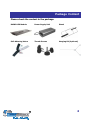
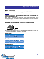
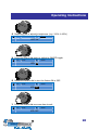
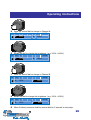
Dear Customer,
Thank you for purchasing this product.
For optimum performance and safety, please read these instructions carefully.
User Memo:
Date of purchase:
Dealer name:
Dealer address:
Dealer website:
Dealer email:
Dealer phone no.:
Please visit us on facebook or twitter!
https://www.facebook.com/Maxspect
http://twitter.com/maxspectled
1
Package Content
Please check the content in the package.
R420R LED Module
Power Supply Unit
Stand
Self-Adhering Velcro
Thumb Screws
Hanging Kit (Optional)
2
Precautions
Before using this Maxspect™ R420R LED Lighting System please read
these operating instructions carefully. Take special care to follow the safety
suggestions listed below.
Afterwards keep this manual handy for future reference.
Before using the Maxspect™ R420R LED Lighting System
1.
2.
Remove any plastic bags and packaging material protecting the fixture.
Never look directly at the LED bulbs when you switch on the system. Incorrect use of this
apparatus will increase eye hazard.
On Safety
1.
2.
3.
Power Source – Do not defeat the safety purpose of the polarized or grounding-type
plug. A polarized plug has two blades with one wider than the other. A grounding-type
plug has two blades and a third grounding prong. The wide blade or the third prong are
provided for your safety. If the plug does not fit into your outlet, consult an electrician for
replacement of the obsolete outlet.
Power Cord Protection – The power supply cords should be routed so that they are not
likely to be walked on or pinched by items placed upon or against them. Never take hold
of the plug or cord if your hand is wet, and always grasp the plug body when connecting
or disconnecting it.
Installation – Install indoor only, and use the attachments, mounting frames, hanging
kit and accessories provided and specified by the manufacturer.
On Operation
1.
2.
3.
4.
5.
6.
Operation – Always follow the operation instructions set forth in this manual when using
this R420R LED Lighting System.
Heat – The apparatus should be situated away from heat sources such as radiators, and
do not expose to excessive heat such as sunshine, fire or the like.
Moisture – To reduce the risk of fire or electric shock, do not expose this apparatus to
rain, moisture, dripping or splashing.
Ventilation – The apparatus should be situated so that its location or position does not
interfere with its proper ventilation.
Magnetism – The apparatus should be situated away from equipment or devices that
generate strong magnetism.
Cleaning – Clean only with dry cloth.
3
Installation
Mounting the R420R LED Lighting System
Before connecting the LED Modules to Power Supply, first mount the system by using the
provided Stand.
1.
Assemble the Stand.
Assemble the stand by inserting the rails into the two holes located to the side of the
R420R LED Module, as illustrated in the following diagram.
2.
Tighten the Thumb Screws.
Tighten the thumb screws to secure the position of the stand.
4
Installation
3.
Mounting the LED Module on your Aquarium.
Using the provided self-adhering Velcro tapes, attach the stand onto the rim of the
aquarium, as illustrated in the following diagrams:
5
Installation
4.
Pendant Mounting
You can also suspension mount the R420R unit, as illustrated in the following diagram:
5.
Mounting the R420R using Ball-Joint System (Sold Separately)
If you already own a set of Maxspect™ ball-joint frame stand, you can mount the R420R
onto the frame using the same ball-joint system, as illustrated in the following diagrams:
6
Installation
7
Operating Instructions
Basic Operations
Follow the instructions below to operate and program the R420R LED Module.
Note
The LED Module turns on automatically when power is connected, and
turns off when power is cut.
When power is resumed, the LED Module will restore to the previous saved setting
automatically, whether it was last set at Manual, Preset or Automatic Mode, and the intensity
level of all the LED channels.
Switching between Manual, Preset and Automatic Mode
1. Press and hold the control dial for 2 seconds to switch between the 3 modes. The
LCD panel will display “M”, “P” and “A” accordingly.
Manual Mode:
M
A:
100%
B:
100%
LED: ON
Preset Mode:
P
12:
A:
100%
30
B:
100%
Automatic Mode:
A
12:
A:
100%
30
B:
100%
8
Operating Instructions
Manual Mode “M”
Under Manual mode, user can adjust the brightness of the two channels by using the control
dial.
1. Press the control dial once to enter setup. Channel A will be selected by default.
M
A:
100%
B:
100%
LED: ON
2. Rotate the dial to adjust its brightness. (e.g. 100%
M
A:
60%
B:
60%)
100%
LED: ON
3. Press the control dial again to switch to Channel B.
M
A:
60%
B:
100%
LED: ON
9
Operating Instructions
4. Rotate the dial to adjust its brightness. (e.g. 100%
M
A:
60%
B:
85%)
85%
LED: ON
5. Press the control dial again to switch to ON/OFF toggle.
M
A:
60%
B:
85%
LED: ON
6. Rotate the control dial to turn the fixture ON or OFF.
M
A:
60%
B:
85%
LED: OFF
7. Press the control dial one more time to exit.
M
A:
60%
B:
85%
LED: OFF
10
Operating Instructions
Preset Mode “P”
Under Preset mode, the fixture will be running the following predefined photo-period profiles.
Under Preset mode, the LCD panel will display the current time and time-point. (e.g.
the following diagram illustrates the current time lies between time-point 3 and 4.)
P
1
A:
100%
2
3
4
B:
5
6
100%
1. Press the control dial once to enter setup. Preset #1 will be selected by default.
P
Preset1
S
Preset2
2. Rotate the dial to select the desired preset profile. (e.g. Preset1
P
Preset1
S
Preset2
Preset2)
11
Operating Instructions
Automatic Mode “A”
Under the Automatic mode, users can program their own photo-period profile using 6
Time-Points.
Understanding Time Points
There are a total of 6 Time Points. You can program different luminous output intensity at each
Time Point to control the photoperiod and brightness of the system.
For example, the following table demonstrates how you could program the Time Points such
that the system would increases light gradually from 8:00am, peaks at 10:00am-2:00pm then
slowly decreases light until it is turned off at 10:00pm.
TP1
TP2
TP3
TP4
TP5
TP6
08:00
09:00
10:00
14:00
18:00
22:00
Channel A
OFF
50%
100%
100%
50%
OFF
Channel B
OFF
50%
100%
100%
50%
OFF
The following diagram would illustrate how the 2 LED channels would behave once the above
Time Points have been programmed.
100%
50%
10:00pm
9:00pm
8:00pm
7:00pm
6:00pm
5:00pm
4:00pm
Channel B
3:00pm
2:00pm
1:00pm
12:00pm
Channel A
11:00am
10:00am
9:30am
9:00am
8:30am
8:00am
0%
Setting up Moon Light
Moon-Light can be programmed by simply assign one of the LED channels (preferably the blue
LED channel) to operate at 1% brightness in the last Time Point.
TP1
TP2
TP3
TP4
TP5
TP6
08:00
10:00
14:00
22:00
18:00
22:00
Channel A
OFF
50%
100%
100%
50%
OFF
Channel B
1%
50%
100%
100%
50%
1%
12
Operating Instructions
Under Automatic mode, similar to the Preset mode, the LCD panel will also display the
current time and time-point. (e.g. the following diagram illustrates the current time
lies between time-point 3 and 4.)
A
1
A:
100%
2
3
4
B:
5
6
100%
1. Press the control dial once to enter setup.
A
TIME
S
PROGRAM
2. Rotate the dial to select between which setting you wish to change. (e.g. Time
Program)
A
TIME
S
PROGRAM
3. Press the control dial again to select the setting.
13
Operating Instructions
Automatic mode – Setting the clock
1.
A
Once you are in the clock setting mode, the hour digit is selected by default.
TIME:
S
2.
A
06:
Rotate the dial to set the hour. (e.g. 06:30
A
08:
A
S
5.
30
Press the control dial to change to the minute digit.
TIME:
S
4.
08:30)
TIME:
S
3.
30
08:
30
Rotate the dial to set the minute. (e.g. 08:30
08:45)
TIME:
08:
45
When finished, press and hold the control dial for 2 seconds to exit setup.
14
Operating Instructions
Automatic mode – Programming the Photo-Period
1.
Once you are in the program setting mode, Time Point 1 is selected by default.
A
TP: 1
S
A:
100%
8:00
B:
100%
2. Rotate the control dial to select the Time Point you want to modify. (e.g. TP1
TP2)
A
TP: 2
S
A:
3.
100%
B:
100%
Press the control dial to change the time setting for this Time Point.
A
TP: 2
S
A:
4.
9:00
100%
9:00
B:
100%
Rotate the control dial to set the time for the first Time Point. (e.g. 9:00
A
TP: 2
S
A:
100%
10:00)
10:00
B:
100%
15
Operating Instructions
5.
Press the control dial to change to Channel A.
A
TP: 2
S
A: 100%
6.
TP: 2
S
A:
80%
TP: 2
S
A:
80%
80%)
10:00
B:
100%
10:00
B:
100%
Rotate the dial to change the brightness. (e.g. 100%
A
TP: 2
S
A:
9.
100%
Press the control dial to change to Channel B.
A
8.
B:
Rotate the dial to change the brightness. (e.g. 100%
A
7.
10:00
80%
95%)
10:00
B:
95%
When finished, press and hold the control dial for 2 seconds to exit setup.
16
Limited Warranty
Maxspect Ltd. warrants all Maxspect™ R420R LED Lighting System products against defects in
workmanship for a period of 12-months from the date of purchase. If a defect exists during
the warranty period, Maxspect Ltd. at its option will either repair (using new or
remanufactured parts) or replace (with a new or remanufactured unit) the product at no
charge.
THE WARRANTY WILL NOT APPLY TO THE PRODUCT IF IT HAS BEEN DAMAGED BY MISUSE,
ALTERATION, ACCIDENT, IMPROPER HANDLING OR OPERATION, OR IF UNAUTHORIZED
REPAIRS ARE ATTEMPTED OR MADE. SOME EXAMPLES OF DAMAGES NOT COVERED BY
WARRANTY INCLUDE, BUT ARE NOT LIMITED TO, USING AFTER-MARKET LED BULBS AND
MODIFICATION OF THE CIRCUITRY, WHICH ARE PRESUMED TO BE DAMAGES RESULTING
FROM MISUSE OR ABUSE.
DISCLAIMER OF CONSEQUENTIAL AND INCIDENTAL DAMAGES:
You and any other user of Maxspect Ltd. products shall not be entitled to any consequential or
incidental damages, including without limitation, loss of use of the unit, inconvenience,
damage to personal property, phone calls, lost income or earnings. This warranty gives you
specific legal rights and you may also have other rights, which vary from state to state.
MAXSPECT LTD. MAKES NO WARRANTY OR REPRESENTATION, EITHER EXPRESS OR
IMPLIED, WITH RESPECT TO THE PRODUCT'S QUALITY, PERFORMANCE, MERCHANTABILITY,
OR FITNESS FOR A PARTICULAR PURPOSE. AS A RESULT, THIS PRODUCT, IS SOLD "AS IS,"
AND YOU THE PURCHASER ASSUME THE ENTIRE RISK AS TO ITS QUALITY AND
PERFORMANCE.
IN NO EVENT WILL MAXSPECT LTD BE LIABLE FOR DIRECT, INDIRECT, SPECIAL,
INCIDENTAL, OR CONSEQUENTIAL DAMAGES RESULTING FROM ANY DEFECT IN THE
PRODUCT OR ITS DOCUMENTATION.
The warranty, disclaimer, and remedies set forth above are exclusive and replace all others,
oral or written, expressed or implied. At no time will any Maxspect Ltd. dealers, agents, or
employees be authorized to make any modifications, extension, or addition to this warranty.
Some states do not allow the exclusion or limitation of implied warranties or liability for
incidental or consequential damages, so the above limitation or exclusion may not apply to
you.
17
Specifications
LED Module
Dimensions (L x W x H)
R420R – 160w
690mm × 265mm x 25mm
(27” x 10” x 0.9”)
R420R – 120w
520mm × 265mm x 25mm
(20.5” x 10” x 0.9”)
Power Supply Unit
Weight
2 kg (4.4 lb)
Model
Input Voltage / Current
Output Voltage / Current
Weight
Meanwell NES-200-36
4.5A/115VAC - 2.5A/230VAC
36V 5.9A
2 kg (4.4 lb)
Note:
For latest specifications on LED layout, types and color spectrum, please visit our website at
www.maxspect.com
Specifications are subject to change without notice.
Weight and dimensions are approximate.
18
Maxspect Limited
www.maxspect.com
NOTE: Products, packaging, features and specifications are subject to change.
All screen images are simulated.
© 2009-2012 Maxspect Limited. Reproduction in whole or in part without written
permission is prohibited. All rights reserved. Maxspect and R420R are trademarks
of Maxspect Limited. Cree and XLamp are trademarks of Cree, Inc.
R420R Owner’s Manual Version 1.0.0
19