1
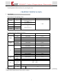
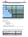
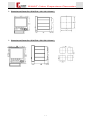
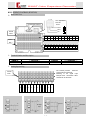
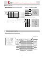
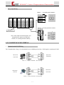
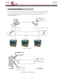
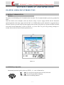
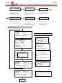
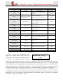
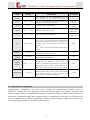
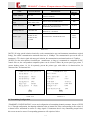
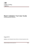
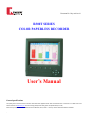
Document No. Oky-m01-rc-06 R300T SERIES COLOR PAPERLESS RECORDER User’s Manual General specifications This operating manual contains the technical information about R300T Series paperless Recorder. Other instrumentation which is available and is not listed herein can be viewed and download at www.okaway.com. Since new technology developed and existing products are updated without prior notice, Please contact your representative or the OKAWAY sales center in Markham, Ontario, Canada to ensure you have the latest instrumentation documentation. - Table of Contents SECTION 1 GENERAL DESCRIPTION CHAPTER 1 FEATURES AND BENEFITS………………………………………………………………………………..…………..…. 4 CHAPTER 2 TECHNICAL DATA .................................……………....……....…………………………………...…………………........ 6 CHAPTER 3 ORDERING INFORMATION..........................................……………….……………………………………………….....11 CHAPTER 4 INSTALLATION AND WIRING.............................................………...………………………………………………........12 4.1 INSTALLATION INSTRUCTIONS....................................…….………………………………………………………..…....….12 4.2 WIRING DIAGRAM........................................................................………………………........………………………….…….….13 4.2.1 R300T100 WIRING..................................................................……………………….........………………………………..…13 4.2.2 R300T200 WIRING..................................................................……………………….......…………………………………....16 4.2.3 R300T100 COMMUNICATION WIRING.....................................…………………..........……………………………...…19 SECTION 2 DISPLAY AND OPERATION CHAPTER 1 OPERATING INSTRUCTION...........................................………………………………………………………………...... 21 1.1 DISPLAY INTRODUCTION ....................................................………………………………………………………..….….... …21 1.2 KEYS OPERATION.........................................................………………………..………………………………......... ……………21 1.3 SPECIAL KEYS FUNCTION.......................................…………………………………….....………………………………..….22 CHAPTER 2 SCREEN DISPLAY........................................................………………………………....…………………………….......... 23 2.1 MAIN SCREEN- REAL-TIME MULTIFUNCTION DISPLAY ........……………........………………………………...……23 2.2 INSTANT ALARMS DISPLAY .......................................................………………………………………………………….... …25 2.3 DUAL CHANNELS REAL-TIME DIGITAL DISPLAY .....................…………….......………………………….…......... ….25 2.4 TOTAL CHANNELS REAL-TIME DIGITAL DISPLAY...................…………….........………………………….…........ ….26 2.5 ALARM SUMMARY DISPLAY..................................................………………………...…………………………………....….26 2.6 BARGRAPH CHART DISPLAY ...................................................…………………………………………………………...…... 27 2.7 HISTORICAL RECORDING TREND .........................................……………………......……………………………..…....…..28 2.8 INSTRUMENT DESIGN AND WIRING SCREEN.....................…………..…………....………………………..…….…. …30 SECTION 3 CONFIGURATION CHAPTER 1 OPERATION INTRODUCTION............................................………………………………………………..…..31 CHAPTER 2 CONFIGURATION AND PARAMETERS......................................……………………………………….…..33 2.1 INTRODUCTION ……………………………………………………………………..……………………………………..…...33 2.2 SYSTEM CONFIGURATION …………………………………………………………………………………………………33 2.3 CHANNEL CONFIGURATION …………………………………………………………………………………………….…34 2.4 ALARM CONFIGURATION …………………………………………………………….…………………………………….36 2.5 COMMUNICATION CONFIGURATION …………………………………………………………………………………....37 2.6 TRANSMITTING CONFIGUIRATION ……………………………………………………………………….……………..38 2.7 SCREEN CONFIGURATION …………………………………………………………………………………………….……39 - SECTION 4 COMMUNICATION AND PRINTING CHAPTER 1 COMMUNICATION...............................................……………………………...........…………………………….…….......40 1.1 COMMUNICATIONSDESIGN.........................................…………………………………………………………………….…..40 1.2 USB FLASH ROM CONNECTION............................……………………………….............………………………………….…41 1.3 SR_BUS COMMUNICATION PROTOCOL ....................……………………………………......………………………….……41 1.4 MODBUS_RTU COMMUNICATION PROTOCOL ...........……………………………………..……………………………..44 CHAPTER2 PRINTING...............................................................………………………………..........……………………………….…..…45 2.1 TIMED PRINTING.........................................…………………………………………………………………………………....…..45 2.2 HISTORICAL PRINTING.........................................…………………………………………………………………………....…..45 SECTION 5 MAINTENCE MAINTENCE.......................................... …………………………………………………………………….....………………..…………46 R300T Color Paperless Recorder SECTION 1 GENERAL DESCRIPTION CHAPTER 1 BENEFITS AND FEATURES BENEFITS R300T Color Paperless Recorder is an advanced paperless recording instrument, which developed, based on the years of expert experience and solid technologies foundation. R300T is designed for advanced features and high quality performance. The instrument uses high brightness and wide viewing angle 5.6” (10.4”) large TFT color Liquid Crystal Display (LCD), updates and uses new hardware structure, and improves anti-interference ability. R300T is convenience to use under different conditions at control room or field. FEATURES Multi-channel Input and Output Inputs: Variety type of input signals can be mixed, 12 Channel (Maximum) Powered Outputs: 24V DC, 6 Channel (Maximum) Relay Outputs: 12 Channel (Maximum) Multi-Function Screen Display: Using 5.6 inch TFT LCD Display Panel, it can display English /Chinese menu, Input signal, Measured and calculated values, Processing data, Engineering units, Trend curves, Bar-graph display, Output and alarm condition, Historical trending, etc. Quick and Easy Front Panel Operation: Quick and Easy English/Chinese Menu,Helping user to complete the parameter settings step-by-step; Clarity English Chinese Information, Indicating and displaying the engineering meaning of the data; Enriched Graphical Display, Providing the combination of all the required parameters; Easy-Touch Front-Panel Keypad. All the operations are user-friendly; Screen Display: Large Screen Liquid Crystal Display (LCD) Graphic Display Screen with adjusted Lighted Background. display in English characters, aphetic letter process curves and light spot. Press keys on the front panel to change screens, search historical data backwards and forwards, adjust contrast of the screen display and change screen time axis settings Parameters Setting: Basic configuration: press front panel keys with English /Chinese menu prompt, technical configuration: using communication port and software, higher lever with password protection. 4 R300T Color Paperless Recorder Alarm Function: Every channel can set up to 4 alarms, alarm configuration includes: high alarm or low alarm output selection, alarm output delay time, alarm dead band, relay contact output (using 4 relay repeatedly), alarm buzzer output, as well as external alarm horn contact and automatic change to alarm screen. Every channel will keep the latest 16 alarm information. Controls: Select ON/OFF relay contact output with dead band, the capacity of contact is AC220V/3A Communication Output: RS232/485 Baud Rate 1200 ~ 57600pbs (TTL electric level,right side port) Baud Rate 1200 ~ 19200pbs (with optical isolation,rear panel port Protection: Parameters configurations saved permanently when power off, use special designed WATCHING DOG circuit to keep parameters safety. Printing: Supply serial port connection (i.e. LQ-300K) with additional order option, Connect to panel mount micro printers or printer with serial port connector, it is ideal to print historical data or curves. High Capacity Memory: Pre-installed high capacity internal memory, maximum 192 M Bit Memory. Every recorded point will keep its largest and smallest values during the measurement,even though recording the transience changes. Additionally, data can be saved to the high capacity external FASH MEMORY ROM for further use. Communication Rate: Unit comes with bi-directional serial communication port; it can exchange the data to the upper level peripherals or other related devices with baud rate up to 57600 bps. RS-232 or RS-485 communication method can be choose. Flexible Additional Functions: Using additional modules and corresponding parameters setting, instrument can provide analog altering signal output, printer interface signal output, direct current power output, standard bi-directional serial communication port, alarm buzzer output, etc. Flexible calculation channel method will realize many requirements with special functions. Powerful Trending Function: Single Step Trending; Continuous Automatic Trending (Trend speed up to 20 steps adjustable); 5 R300T Color Paperless Recorder Searching Trending by time; Searching historical data and curves by moving the Axis. CHAPTER 2 TECHNICAL DATA Input Signal Input channels and sampling period Model Inputs R300T02 2 R300T04 4 R300T06 6 R300T08 8 R300T12 12 Sampling period 250ms (Refresh Cycle: 1s) 500ms (Refresh Cycle: 1s) Record Interval 1-240s 1s (Refresh Cycle: 1s) Input types and scale range and accuracy: Input Types Voltage (DC) Current (DC) Range Measurement Range Accuracy 0~20mV -9999~99999 ±0.1% 0~100mV 0~5V 1~5V -9999~99999 -9999~99999 -9999~99999 ±0.1% ±0.1% ±0.1% 0~100mA -9999~99999 ±0.2% 4~20mA -9999~99999 ±0.2% -50.0~100.0℃ ±3.7℃ B K E J T Wer3-25 100.0~1768.0℃ 0~1820.0℃ -50.0~1372.0℃ -50.0~1000.0℃ -50.0~1200.0℃ -199.90~320.00℃ 0.0~2300.0℃ ±2℃ ±2℃ ±2℃ ±2℃ ±2℃ ±2℃ ±5℃ Pt100 -200.0~850.0℃ ±1℃ Cu50 -50.00~150.00℃ ±1℃ S TC RTD DI Frequency Voltage (DC) Input (TTL) OFF:< 2.4V ON: >2.4V Contact Input Contact:on/off 0—15khz 0~99999 ±1 (Normal Operating Conditions: 23±2℃, 55±10%RH, power supply: 90~260VAC, 50/60Hz±1%, preheating >30mins, and vibration has no effect on the recorder.) 6 R300T Color Paperless Recorder Cold Junction Compensation: Internal temperature compensation; direct temperature compensation setting; Special channel temperature compensation. Cold Junction Compensation Accuracy: S、B、Wre: ±1℃ K、J、E、T: ±1℃(Measured when ≥0℃) Maximum Input Voltage: Voltage range ≤2VDC and thermocouple:±10VDC(continued) Voltage range ≤6VDC: ±50VDC(continued) Input Impedance: ≥10 MΩ on lower than 2 VDC Ranges ≈ 1 MΩ on lower than 6 VDC Ranges External Input Impedance: DC Voltage, Thermocouple input: ≤ 2KΩ RTD Input: each wire ≤10Ω, (3 wires must be equal) Biased DC Current: ≤10nA Common Mode Interference Voltage:250V AC rms(50/60 Hz) Common Mode Rejection Ratio (CMRR): 120dB (50/60Hz±0.1%, 500Ω unbalanced ground terminal---negative) Series Mode Rejection Ratio (SMRR) :40db (50/60 Hz±0.1%) Channel Interference Voltage:Max. 250VAC rms(50/60 Hz) Channel Interaction:120dB(input external impedance 500Ω,voltage of input to other channels: 60V) Output Signal Analog Output: Current Voltage 0~10mA(Load≤750Ω) 4~20mA(Load≤500Ω) 0~5V (Load≥250KΩ) 1~5V (Load≥250KΩ) Digital Output: Relay Contactor rate SSR Output Sourcing Output AC220V/3A or DC24V/5A(resistive load) 400V/0.05A 5~24V/0.05A DC24V/25mA (isolated current limited) Display Display Type : 5.6”(10.4”)TFT Color LCD(320×234 dot matrix) Curve/Bar Graph Display Color: 8 colors Background Color:Black is default color; white is an option. Display Modes: Measuring data display (curve display, digital display, bar graph display), full channels display, one channel display (recent alarm overview display, alarm historic overview, recorder setting information overview, report form overview), historic recording display. 7 R300T Color Paperless Recorder Curve Display: Display group Channels in one group Upgrade cycle of wave form Direction Scale Other information display Maximum 6 groups Maximum 4 channels Same as Recording Interval Vertical or Horizontal 4-12 division Data, grid, Time/Date, courser, communication status, wire burnout Engineering unit, Digital Display: Channels in one screen Display contents Full channels display Display contents Overview display Recording Rates Dual or Full Channels Refresh rate: 1second Measurement data, unit, alarm status, and time/date Refresh rate: 1second All Channels measurement data, and Alarm status Display contents:Alarm, information, and Event overview Programmable from 1 second to 240 seconds Alarm: Programming:4 alarm set points per channel Alarm Types: High/Low alarm, alarm delay (0 to 7 seconds, applicable to all channels) Display: Display Alarm status (alarm types) in data display section, and can be set to auto switch to current Alarm/Event overview display screen. Data Storage: Storage information:Alarm On/Alarm Off Time,Alarm Types, and Alarm Point. Storage Capacity:Maximum 120 messages Alarm Sound:Buzzing, or external sound by programming relay outputs Output: Relay output contacts: 2, 4, or 8,12 Action:Excite/no excite, retention/ no retention Alarm Relay Output(/J0-/J12) Output: 0-12 normally open contacts Option: 0-6 normally open/normally close contacts Contactors rating: 30V DC / 5A (resistive load) 250V AC (50/60 Hz) / 5A Output types: NO-C-NC(Excite/No Excite, AND/OR Retention/No Retention) Serial Port Communication(/C2,/C3) Feature: Controlling and programming by PC, and transfer data to PC. Media: Comply with EIA RS-232(/C2), or RS-485(2 wires) (/C3) Protocol:SR-BUS, or Modbus RTU protocol Synchronous Mode: Start/Stop Communication Mode(RS-485) :2 wires semi-duple multipoint connection(1:N,N=1~32) Transfer Rate:1200,2400,4800,9600,19200, 38400, 57600bps Data Length: 8 bits Stop Bit: 1bit Odd Even Effect:Non Longest Distance:1.2 km(RS-485) 8 R300T Color Paperless Recorder Communication Mode: ASCII is for special protocol input/output, and MODBUS protocol for binary mode. Modbus Communication: Action Mode:RTU SLAVE 24V DC Transmitter Power Output(/P1-/P6) Output Voltage: 22.8~25.2V DC (at rated load current) Rated Output Current: 4~20mA Maximum Output Current: 25 mA DC(isolated current limited output) 60 mA DC (special order) Wire Resistance Range: RL<(17.8V transmitter threshold voltage) /0.02A (excepted voltage drop on 25Ωload resistor) Maximum Wire length: 2 km(using CEV Cable) Isolation Resistance: Output to grounded ≥20MΩ(500V DC) Isolation Voltage: Output to grounded 500V AC(50/60Hz;i=10mA) ;1 minute Terminal to Terminal: 500V AC(50/60Hz;i=10mA) ;1 minute Memory Capacities Measurement Data:4bytes per data Recording Data: 4bytes per channel recording point (Recording Max/Min data in the time interval) Installation Panel mounted (vertical panel), and locking bar assembly. Allow to lean back < 30° Dimensions: Panel Cutout 144×144×240 mm (R300T100) 138×138 mm 288×288×240 mm (R300T200) 281×281mm Power Supply Nominal Voltage: 220VAC +10-15% Voltage Ranges: 90~260 VAC Rated Power Frequency:50~60 Hz Power Consumption: < 25W Temperature Range: 0~50℃ RH Range: 20~80% RH(5~40℃) Weight: R300T1 Approx. 2700 g R300T2 Approx. 4000 g 9 R300T Color Paperless Recorder Memory Capacity: Maximum Capacity: 192MBit; Data Recording Time according to number of channels, memory size and recording time interval 8 see the table as follow: CAPACITY (M bit) RECORD INTERVAL (S) No. of CHANNEL APROX.RECORD TIME(DAY) 1 152 2 76 4 38 10 64 8 18 (MANUFACTURE 12 12 R 1 3663 2 1831 4 915 8 438 12 292 1 327 2 163 4 81 8 39 128 12 26 (OPTIONAL) 1 7850 2 3925 4 1962 INSTALL) 240 10 240 8 938 12 625 1 501 2 250 4 125 8 59 192 12 39 (OPTIONAL) 1 12037 2 6018 4 3009 8 1439 12 960 10 240 10 R300T Color Paperless Recorder CHAPTER 3 ORDERING INFORMATION Ordering Code Model Code R300T1 R300T2 Channels - - - - / Description Dimension 144X144 Dimension 288X288 02 ~ 12 For R300T1 *1 02~ 32 For R300T2 Memory Capacity -1 -2 -3 -0 -1 Language Additional Option *1 *2 *3 Additional Code / /J(1-12) /JB(1-8) /P(1-6) /C2 /C3 /AO(1-4) /F(1-4) 64 Mbit (Standard) 128 Mbit 192 Mbit English Chinese N.C output Channels N.O/N.C Output Channels DC24V Sourcing Channels RS-232 Connector *2 RS-485 Connector *2 Transmitter Output Channels *3 Frequency Input Channels *3 Able to provide maximum 16 channels for special order. Cannot select /C2 and /C3 at same time. If use micro-printer, the RS-232 connector must selected. If choose analog output or frequency input, maximum 8 universal channels are available. Example of Ordering Code: R300T106-2-0/J4 /C2 R300T1---- Color Paperless recorder 06----- 6 input channels 2----- 128 Mb memory 0----- Chinese (Simplified) /J4----- 4 normally open contacts output /C2----- RS232 connector Note*: The instrument, with RS232 communication function, can connect to printers with serial port and print. Part List ITEM SET R300T Recorder 1 R300T Operating Manual Mounting Bracket 1 2 11 R300T Color Paperless Recorder CHAPTER 4 INSTALLATION AND WIRING 4.1 INSTALLATION INSTRUCTIONS Installation Instructions Before installation and wiring, read the attached nameplate carefully about details of type, power supply. Avoid mounting on the following locations: Atmosphere Temperature lowers than 0oC degree or higher than 50 oC Atmosphere Humidity lower than 10% or higher than 90% Atmosphere with Corrosive gases Possible spurt of water, Oil, Chemicals, Vapor or Steam Do not mount this instrument directly above equipment that generates large amount of heat or heavy shaking Do not mount this instrument close to the equipment with strong electro-magnetic interference. Installation Procedure In order to mount the recorder, you need a steel plate thicker than 2mm as a panel, with a designed cutoff hole. Procedure of installation as follows: 1. Take out the mounting brackets from the instrument package 2. Through it in the cut off hole from the front of the panel. 3. Fit the mounting brackets into the square holes in the top and bottom surface of the case. 4. Tighten the screws of the mounting brackets with a screw driver , let it fixed to the panel. Installation Figure Panel Mounting bracket Screw with a screwdriver Terminal block 1 Mounting Direction Terminal block 2 Panel FIG 4-1-1 12 Mounting bracket R300T Color Paperless Recorder Dimensions and Cutout Size(R300T100 144×144×240 mm) Dimensions and Cutout Size(R300T200 288×288×240 mm) 13 R300T Color Paperless Recorder 4.2.1 WIRING DIAGRAM (R300T100) Rear Panel View L N G Power supply Terminal AC90~260V 50/60Hz Communication Connector Ground Neutral Terminal Line block 2 70 71 67 68 64 65 61 62 58 59 55 56 52 53 49 50 46 47 43 44 40 41 37 38 34 35 36 31 32 33 28 29 30 25 26 27 22 23 24 19 20 21 16 17 18 13 14 15 10 11 12 7 8 9 4 5 6 1 2 3 Terminal block 1 Terminal Number and Description Terminal No. 1 - 36 25 - 36 Description Analog Signal Input Transmit output、frequency and digital input Terminal No. 37 - 48 49 - 72 Description 24VDC Sourcing Output Relay Output Analog Input wiring The recorder provides maximum 12 universal input channels. A Following is the signal input example of No. 1 Connection. Other B connections are the same. C Terminal block 1 No. No. No. No. No. No. No. No. No. No. No. No. 12 11 10 9 8 7 6 5 4 3 2 1 A + A DC Voltage B C + Input _ C _ A Resistance Thermoc B C 14 C R300T Color Paperless Recorder Multi-Function Terminals Wiring Terminal No.9-12 terminals are multi-functions terminal, when they connected special signal, the recorder is able to provide maximum 8 universal input channels. Block 2 CH4 Digital Input Frequency Input Analog Output CH3 CH2 CH4 CH1 A + B C _ CH1 DC Voltage F Input + + _ _ _ CH1 CH2 _ +12V Output C CH5 CH3 CH6 CH8 + DC Current Output CH3 CH2 CH1 CH2 DC24V Sourcing Output Wiring P4+ P5+ P6+ Terminal Block 2 C 2-wires Transmitter Wiring P1+ P1- B C 3-wires Transmitter Wiring 15 P1+ P2+ P3+ P1P2P3- A P1+ P1- B C 4-wires Transmitter Wiring Transmitter B A Transmitter P1+ P1- Transmitter A P4P5P6- R300T Color Paperless Recorder Note:Provided maximum 6 channels of DC 24V/25mA isolated current limited output. If need high current capacity, please indicate when you place order. Relay Output Wiring Option 1 (3 normally open contacts) J1 J1 J1 Terminal Group 4 Group 3 Group 2 Group 1 J2 Block 2 J3 Option 2(2 normally open/close contacts) J1 Note:Relay output has 4 terminal groups, and each group has 2 options (3 normally open contacts, or 2 normally open/close contacts). NO N.O. C N.C. J2 NC J1 4.2.2 WIRING DIAGRAM (R300T200) Rear Panel View Communication L N G Connector Power Supply AC90~260V 50/60Hz Terminal Block1 Ground Neutral Terminal Terminal Block5 Block2 Line Terminal Terminal Block6 Block3 Terminal Terminal Block7 Block4 16 R300T Color Paperless Recorder Analog Input Wiring Terminal Block 6 Terminal Block 3 No No No 32 31 30 A A B B C C No No No No No No No No No No No No No No No No No 29 28 27 26 25 12 11 10 9 8 7 6 5 4 3 2 1 A The standard R300T200 provides maximum 16 universal input channels. Special model provides maximum 32 universal input channels. Following is the signal input example of No. B C 1 channel connection. Other connections are the same. + DC Current C No No No No No No No No No No No Block4 24 23 22 21 20 19 18 17 16 15 14 13 A DC Voltage B Input Input _ No + A B Terminal C A RTD Thermocouple C _ C Analog Output Wiring Terminal Block 5 B A C + DC Current Output _ B C No No No No No No No No No No No No 12 11 10 9 8 7 6 5 4 3 2 1 A + DC Voltage output C 17 _ R300T Color Paperless Recorder Frequency Input Wiring Terminal Block 6 +12V f Input + _ ` No No No No 4 3 2 1 The standard R300T200 provides maximum 4 frequency input channels. Digital Input Wiring Terminal Block 7 _ CH1 + CH2 _ No No No No 7-8 5-6 3-4 1-2 The standard R300T200 provides maximum 8 digital input channels. DC24V Sourcing Output Terminal Block 1 P10+ P11+ P12+ C Two wires Transmitter P1+ P1- B C Three wires Transmitter P7+ P8+ P9+ P7P8P9- P4+ P5+ P6+ P4P5P6- P1+ P2+ P3+ A P1+ P1- B C P1P2P3- Transmitt B A Transmitt P1+ P1- Transmitt A P10P11P12- Four wires Transmitter Note:Provided maximum 12 channels of DC 24V/25mA isolated current limited output. If need high current capacity, please indicate with you order. 18 R300T Color Paperless Recorder Relay Output Wiring Option 1 (3 normally open contacts) J1 Group6 Group5 Group4 Group3 Group2 J1 J1 J2 Group1 J3 Option 2(2 normally open/close contacts) Terminal Block 2 J1 N.O J2 Note:Relay output has 6 terminal groups, and each group has 2 options (3 normally open contacts, or 2 normally open/close contacts). J1 N.O C N.C N.C 4.2.3 COMMUNICATION WIRING Communication RS-232Wiring For Communication wiring, it is recommended to use a shielding twisted wire, Cable length is a maximum of 10M Red Blue Blue Red Black Black DB9 Connector Computer Side FIG 4-2-1 DB9 Connector Recorder Side Computer and R300T RS-232 Wiring DB9 Connector Printer Side FIG4-2-2 Red Blue Blue Red Black Black Printer and R300T RS-232 Wiring 19 DB9 Connector Recorder Side R300T Color Paperless Recorder Communication RS-485Wiring It is recommended to use a shielding twisted wire; Cable length is a maximum of 1000M. To reduce reflection and noise , be sure to attach terminating resistance ( Rt 120Ω ) to a terminal side(FIG 3-3-7) CONVERTER 120 Ω 120 Ω FIG. 4-2-3 RS-485NET DATA(+) DATA(—) FIG. 4-2-4 RS232 and RS485 CONVERT 20 R300T Color Paperless Recorder SECTION 2 DISPLAY AND OPERATION CHAPTER 1 OPERATION INTRODUCTION 1.1 DISPLAY INTRODUCTION Power Up The power cord will hookup to N, L terminal on the rear panel. The G terminal should be protective grounded for safety. Check the details on the nameplate; make sure that the voltage of power supply satisfied with the instrument required.(generally wide range supply with 90~220V AC, 50/60Hz,unless special ordered) It is suggested that at first time of power up, do not reply any input signals to the recorder. After power up 8 system will show the initial screen and start the initialization,( as show on FIG.II 1-1-1), Press “ESC” key (or no key pressing, waiting for 3 second) ,the recorder will enter the main operation screen. FIGII.1-1-1 1.2 ONPAD Keys Operation Instrument Operation keypad as shown on FIG.II 1-1-1,total 14 function key. “ ”、“ ” Key used for moving the cursor forward, backward. “ ”、“ ” Key used for parameters changing. “ ENT ” Key used for confirming function. 21 R300T Color Paperless Recorder “ESC” Key used for returning from the present operating function or present operating window. On the Main Screen and Historical Trend Screen, “DIV” Key used for change the Division. Total 4 divisions can be changed circularly and displayed different size compressed curves. “SCREEN LOCK” Key used for locking the screen changes. When the screen is locked, a small lock symbol will display on the up-right corner of screen. If the screen is unlocked and no key operations within 4 minutes, the screen will be changed to the Main Screen. (expect on the Recent Alarm Screen) On any screen, pressing “ “, “CONTRAST” Key, the Contrast Adjusting Window will be pop-up on the screen, total 30 steps for contrast adjustment. Pressing “ ” Key will increase the contrast of LCD screen, Pressing “ ” Key will decrease the contrast of LCD screen, Pressing “ESC” Key will return to the original screen. On any screen, pressing “PRINT” Key, the Printing Window will be pop-up on the screen. Pressing “SET” and “ ” at the same time, entering the instrument Configuration Setting Screen. On any screen, pressing “SET” and “ENT” at the same time, entering the Parameters, corresponding to the recent screen, Configuration Setting Screen. “F 1”Used for some special key function, or combined with the other keys to do some special functions, they will be explained on following sections. “F 2”Used for some special key function, or combined with the other keys to do some special functions, they will be explained on following sections. On the displayed screen, Pressing“PAGE DOWN"Key will change to the Forward Screen, Pressing “F 1"and“PAGE DOWN" Key together, will change to the Backward Screen. 1.3 Special Keys Function Following Function Keys and Combination Key will be affective on any screen: “SET”+“ ” Entering the instrument Configuration Setting Screen; “F1”+“ ” Entering the instrument layout and Connection Display; “CONTRAST” “SET”+“ “F1”+“ Open Contrast Adjusting Window. ” Display Help Screen; ” Printout Current Real-Time Data 22 R300T Color Paperless Recorder CHAPTER 2 SCREEN DISPLAY R300T Series Color Paperless Recorder combines the screens as follows: Starting Screen Connection Screen Main Screen : Real-Time Multi-Channel Display Real-Time Alarm Display, Dual Channel Display Full Channel Display Alarm Overview Display Bar-Graph Display Historical Trend Several Configuration Screens Parameter Setting Screens with English/Chinese manual. 2.1 MAIN SCREEN- REAL-TIME MULTIFUNCTION DISPLAY After the recorder is powered on, the Main Screen will be automatically displayed as Opened–Real-Time Multi-Channel Display Screen, as shown on FIG.II 2-1-1. On the top of the Main Screen, there is a display include: System time and relay output conditions, communication status, division value, and recent display group number. The recorder display is divided into 6 groups, each group includes up to 4 channels. Main Screen will display Tag Number, Error mark, Unit, Display mark, Real-Time measuring data, sequel curve Recording pen Division of each channel of the recent group. Ë Ë 4 GROUP DIVIDSION DATE, TIME COMM. SIGN STATUS RANGES RECENT RELAY RECORDING PEN TIME DIVISION (ALONG CURVE RECORD AXIS.CORR.TIME FOR 30 RECORDING CURVE POINTS) TIME DIV. GRID CURVE CHANNEL REAL-TIME VALUE ENGENEERING UNIT ANALOG VALUE FIG.II 2-1-1 Recorder can display vertical curves (FIGII. 2-1-2) , also display horizontal curves (FIGII. 2-1-3) , as well as turnoff measuring data display to enlarge the area of curves display (FIG.II 2-1-3) . All the changes by pressing “SET”+“ENT” key,enter the parameter window related to the screen, (FIG.II 2-1-4) , and to achieve it by simple settings. 23 R300T Color Paperless Recorder FIGII. 2-1-2 FIGII. 2-1-3 Curves Parameter Configuration Group: 1 Channel Color Tag Curve 1: 1 Red CH1 Curve 2: 2 Green CH2 Curve 3: 3 Blue CH3 Curve 4: 4 Purple CH4 Grid: 沨 Grid Move: ON Division: 沨 Ruler Div: 10 Digital Value: 沨 Direction: Horizon Group Number: 6 Exit FIGII. 2-1-4 KEYPAD “DIVISION” 4 divisions can be changed, displaying the curves in different sizes , Using “TIME DIVISION” parameter items in the “SYSTEM CONFIGURATION”,change one kind of selected rate. “ ”、“ ” Moving Curve, point the cursor to each display mark of the channel. “ ”、“ ” When cursor is pointed to the display mark of a channel, these two key can be used to display or hide the curves of this channel, through changing the display mark of channel. “ESC” Moving the cursor away from the display mark of any channel. “F2” Change display group, total 6 groups, each group displays 1 to 4 curves. “F1”+“F2” Turn on/off the function of automatic changing display group, when the automatic changing function is on, instrument will change to the next display group every 4 seconds automatically. “PAGE DOWN” Change to next screen. “SET”+“ENT” Entering curves parameter setting display screen. For all 6 group of display curves, 24 R300T Color Paperless Recorder configuring channel, color, grid/no grid, division, value, setting grid location, grid number, curve direction, and setting measuring group number. 2.2 Instant Alarms Display The screen (FIGII. 2-2-1) will display 4 alarm status of all measuring channels in one screen, it will be easy for operator to find the recent alarm channel and alarm type quickly. In the table which displays 4 alarm point of each channel, displaying “H” presents High Alarm Condition, displaying “L” presents Low Alarm Condition, no display presents no Alarm Condition. In the Recent Alarm Configuration, if the “AUTO CHANGE TO ALARM SCREEN” is ON, when alarm happen, it will change to the Recent Alarm Screen. Real -time CH 1 2 3 4 5 AL3 L L L AL4 L L L 6 7 Alarm 8 9 10 11 12 13 14 15 16 AL1 AL2 FIGII 2-2-1 2.3 Dual Channels Real-Time Digital Display Dual Channel Digital Display Screen (FIGII 2-3-1) displays real-time measuring value of two channels with larger size letter. Therefore operator can easy observe and compare measuring values of the channels in distance. The operator, as required, select any two channels for observe. RECENT TIME RECENT RELAY 第 1 通道工位号 FIRST CH. TAG # FIRST CH. UNIT FIRST CH. VALUE SCREEN NAME SECOND CH. TAG # SECOND CH. VALUE SECOND CH. UNIT FIG. 5-3-1 FIGII. 2-3-1 KEYPAD “SCREEN LOCK” Lock function for screen change, after pressing the key “SCREEN LOCK SIGN” will display or disappear on the upper-right corner of the screen. If no sign display, after 4 minutes no any key operations, display screen will be changed to main, otherwise, the recent screen will be remained. 25 “ “ ”、“ ”、“ R300T Color Paperless Recorder Moving curser, locate the curser to the Tag Number of each display channel.。 When the curser located on the Tag Number of certain channel, setting the channel display by operating these two keys. Moving the curser away from the display mark of any channel. ” ” “ESC” 2.4 Total Channel Real-Time Data Display Full Channel Real-Time Data Display Screen is convenient for user to overview the real-time measuring data of all the using channels. (displayed when more than two channels are used) .The instrument corresponds to the recent total channel number setting, displays the real-time measuring data, engineering unit, and their Tag Numbers of all channels, automatically layout the screen with proper size of characters. As shown on FIG.II 2-4-1、FIGII.2-4-2, are the full channel display screens with 9 channels and 16 channels. 2004-03-26 12:43:58 Whole CH ① CH 1 CH 2 502 2004-03-26 12:43:58 . ② ③ ④ CH 1 CH 3 329 PH CH 5 929 % ℃ CH 7 CH 5 CH 6 49.3 ① 587 510 364 ℃ ℃ ℃ CH 6 CH 7 CH 8 200 446 800 441 ℃ ℃ ℃ ℃ ℃ CH 9 CH 8 CH 4 CH 3 999 ℃ ℃ CH 4 CH 2 502 0.33 mm Whole CH ② ③ ④ CH 10 CH 11 CH12 503 243 472 600 810 226 ℃ ℃ ℃ ℃ FIGII 2-4-2 ℃ ℃ FIGII 2-4-1 2.5 Alarm Summary Display RECENT DATE & TIME 2004-03-26 12:43:58 Alarm ① RECENT RELAY STATUS ② ③ ④ TOTAL OR CHNNL MARK ALARM NUMBER ALARM START TIME ALARM END TIME Pandect Starting Time 01 Ending Time Type SCREEN NAME 2002-01-12 16:30:20 2002-01-12 16:31:33 01-1H 2002-01-12 16:30:20 2002-01-12 16:31:33 01-1H 2002-01-12 16:30:20 2002-01-12 16:31:33 01-1H 2002-01-12 16:30:20 2002-01-12 16:31:33 02-1H 2002-01-12 16:30:20 2002-01-12 16:31:33 01-1H 2002-01-12 16:30:20 2002-01-12 16:31:33 01-1L 2002-01-12 16:30:20 2002-01-12 16:31:33 01-1H ALARM TYPE 2002-01-12 16:30:20 2002-01-12 16:31:33 01-1H L : LOW ALARM 2002-01-12 16:30:20 2002-01-12 16:31:33 01-1H H :HIGH ALARM FIGII 2-5-1 26 ALARM CHANNEL(01-16) ALARM POINT (1-4) R300T Color Paperless Recorder Alarm Historical Recording Overview Display Screen displays the latest 16 lines of alarm recording of the instrument, or the latest 16 lines of alarm recording of each channel. Every Record includes: Alarm Starting Time, Alarm Ending Time, Alarm Channel, Alarm Point, Alarm Type. As shown on FIGII. 2-5-1. KEYPAD KEYPAD “ ”、“ ” “F2” “F1”+“F2” 2.6 Moving Cursor,locates cursor to the different alarm recording. Change the displayed latest 16 records of each channel alarm record or Summary alarm record. Change display (1-16) or (17-32) record of the alarm recording. Bar-Graph Chart Display Bar-Graph Screen, separating into 6 groups, can display multi-channel bar-graphic picture, it is easy to directly observe multi-channel real-time situation. As shown on FIGII. 2-6-1,There are display of recent date, time, groups number and relay output status on the top of screen. The instrument corresponds to the recent total channel number setting,automatically layout the screen with proper size of Bar-Graphs. Inside the Bar-Graphs displays percentage scales, upper and lower side of Bar-Graphs displays the corresponding channel ranges,Right side of Bar-Graphs displays the alarm signs.(GREEN means normal,RED means alarm) ,Lower side of screen displays Tag Number, Measuring Values and Engineering Unit. GROUP NUMBER SCREEN NAME RECENT RELAY RECENT DATE, TIME RANGE UPPER LIMIT HIGH ALARM POINT PERCENTAGE SCALE LOW ALARM POINT BAR-GRAPH RANGE LOWER LIMIT CORR. CHNNL. TAG No. REAL-TIME DATA ANALOG VALUE SIGN ENGINEERING UNIT FIGII 2-6-1 27 R300T Color Paperless Recorder KEYPAD “F2” “F1”+“F2” Change display group,total 6 groups, every group display 1 - 4 curves. ON/OFF automatic changing display group function, when automatic changing function is on, instrument automatically changes to next group display every 4 seconds. “SET”+“ENT” Enter Curve Display parameters setting screen. It can set corresponding channels, colors for the 6 groups’ Displaying Bar-Graph Screen. 28 R300T Color Paperless Recorder 2.7 Historical Trend Historical Recording Trend Screen is used for research of historical data. Its screen display is similar to the main screen, as shown on FIGII. 2-7-1, its picture display is similar to the main screen, shown as FIGII.2-7-1.The difference are, under the Real-Time time display line, it displays only the range of time interval of recent trend recording, and in the data display, it displays the high limit value and low limit value of measuring data during the interval. In the curves area, an additional dot line, which represents the position axis of trend recording, will use for marking the location of recent trend recording point. There are three types of Trending Screens including Single Trend, Continuous Trend, and Timely Trend. They can be selected by pressing “NEXT PAGE” key to change the function mark on the lower right corner of screen. Different function marks means different function and keypad operation, they will be described respectfully as follow: There are three types of Trending Screens including Single Trend, Continuous Trend, and Timely Trend. They can be selected by pressing “NEXT PAGE” key to change the function mark on the lower right corner of screen. Different function marks means different function and keypad operation, they will be described respectfully as follow: RECENT DATE & TIME TREND FUNCTION MARK TREND RECORD TIME RANGE GROUP NUMBER TREND RECORD POSITION TREND CURVE CHANNEL TAG NUMBER CURVE DISPLAY SIGN MEAS. LOW LIMIT VALUE ENGINEERING UNIT MEAS. HIGH LIMIT VALUE ANALOG DATA SIGN FIGII 2-7-1 KEYPAD “DIVISION” “SET”+“ENT” “ “ ”、“ ”、“ “ESC” “F2” “F1" ” ” Change to 4 step division, the curves can be amplified or dwindled to different size, using “DIVISION SELECT” parameters of “SYSTEM CONFIGURATION”,change to a selected size. Enter the screen of curves display parameter setting, For 6 group display curves, setting corresponding channels, color, grids display, scale, value, grid position, scale division and curves direction. Moving cursor, locate cursor to the selected display mark of each display channel. When cursor was located on the display mark of a channel, using these two key to adjust the display mark of the channel, it will display or hide the curves of the channel. When cursor was not located on any display mark of the channel, other trend operations can be done. Make the moving cursor not located on any display mark of the channel, the trend operations will be returned to display the recent relay status. Change display group, total 6 groups, each group displays 1-4 curves. Change trend functions, trend function displays in turn as: 4 relays output status,“SINGLE 29 R300T Color Paperless Recorder TREND" 、“CONTINUE TREND" 、“TIMELY TREND"。The key functions of different trend function condition will explain as follow: RELAY STATUS Key Function as above. SINGLE TREND Trend curves or trend record position axis move one lattice forward or on lattice backward. “ENT” Change the record trend position axis to solid line or dot line. “ ” For horizontal curve, when position axis is dot line, curve moving left one lattice; when position axis is solid line, position axis moving left one lattice. “ ” For horizontal curve, when position axis is dot line, curve moving right one lattice; when position axis is solid line, position axis moving right one lattice. “ ” For vertical curve, when position axis is dot line, curve moving up one lattice; when position axis is solid line, position axis moving up one lattice. “ ” For vertical curve, when position axis is dot line, curve moving down one lattice; when position axis is solid line, position axis moving down one lattice. CONTINUOUS TREND After trend direction is confirmed, system will automatically move trend curve according to the pre-set interval. “ESC” Quitting Continue Trend, “ ” For horizontal curve, curve continually moves one lattice left. Function Indication becomes << 01. “ ” For horizontal curve, curve continually moves one lattice right. Function Indication becomes >> 01. “ ” For vertical curve, curve continually moves one lattice up. Function Indication becomes︽ 01 . “ ” For vertical curve, curve continually moves one lattice down. Function Indication becomes︾ 01. << 01 、>> 01 、︽ 01、︾ 01 Continue Trend,“〈 〈”means curve moved left,“〉〉” means curve moved right,“︽” means curve moved up,“︾” means curve moved down. Value means the lattice number on each moving, select 1 to 20 total 20 step by the key of “ ”、“ ” or “ ”、“ ”. “ESC” Quitting Continue Trend, TIMELY TREND Enter trending time, then searching the historical recording point. First, press “ENT” key,a trending time setting window will display on the screen, shown as follow: Use“ ”、“ ”keys moving cursor to the digits TREND TIME SET location of year, month, day, hour, minute and second. Use“ ”、“ ” key to modify the digits 2002 Y 06 M 07 D which cursor pointed, setting date and time of the 10 H 35 M 38 S searching historical data, then press “ENT” key to OK EXIT confirm. Now system will search the record according to the set date and time. If find, the curve 02-06-06 15:25:58~02-08-07 10:35:38 position axis will be located to the searching point. FIGII.2-7-2 30 R300T Color Paperless Recorder If not find, the setting window will return, and entering the new trending time will be required. 2.8 Instrument Design and Wiring Screen In any screens, pressing“F1”+“ ” Key at the same time, the screen will change to Instrument Layout and Connection Display Screen. It can display the memory capacity, free space, recording starting time, channel number, recording interval, and calculating result of total possible recording time under the current setting condition. Displaying recent instrument connection screen will be convenient for the instrument maintenance person to understand the situation of instrument wire connections, to prevent the wrong insertion of circuit boards amount several instruments and cause the actual connections are different from the connection diagram of instrument terminals, as shown on FIGII. 2-8-1. This instrument has 4 channel Inputs, 5 channel DC24V powered outputs, 10 channel relay output. Ver1.68-000000000 Color Paperless Recorder Capacity 128 M bit Free Space 99% Channels 4 Record Interval 4 Sec. Recording Time 32 J10A J10B D 17 H 04 M 00 S J7A I7B J4A J4B J1A J1B P5- P4- P1+ P1- J8A J8B J5A J5B J2A J2B P5+ P4+ P2+ P2- J9A J9B J6A J6B J3A J3B P3+ P3- RTD1 RTD1 RTD1 RTD1 RTD2 RTD2 RTD2 RTD2 〧 FIGII. 2-8-1 KEYPAD “ESC” Return to main screen. 31 〧 〧 R300T Color Paperless Recorder SECTION 3 DISPLAY AND OPERATION CHAPTER 1 CONFIGURATION T300R Paperless Recorder uses complete English/Chinese characters and styles to set up the parameters configuration of the instrument, with friendly interfacing between human and machine, operators will be able to handle the parameter configuration settings in very short time. 1.1 Operation Introduction Enter Configuration Screen In any screen, pressing“SET"+“ "Key at the same time, entering configuration screen. Moving Cursor In the configuration screen, pressing “ cursor backwards. "Key, it will move cursor forwards, Pressing“ "Key moves Confirm Operation In the configuration screen, pressing“ENT"Key, It will confirm the function. Instrument Unlock Password:000000 * System Set Channel Set Alarm Set Communication Set Transmitting Set Screen Set Exit Password:000001 * System Set Channel Set Alarm Set Communication Set Transmitting Set Screen Set Exit Password:000000 System Set Channel Set Alarm Set Communication Set Transmitting Set Screen Set Exit Press “ set” and “ ”key ——enter config. Page menu Enter unlock password: i.e.:use 000001as an example —— / . Press cursor. Press key, inc / dec value at / key, cursor move left/right two digit each time. Press “ ” key confirm password: If password is correct —— then:passwor display change to :000000 “*”sign will disappear cursor moved to first item of menu Otherwise— cursor will stay at the same place Complete unlock, setting parameters “*”sign still shown Modify Data (Unlocked) In the Parameter Configuration,There two way to modify the value, shown as following: No.1:Press / key modifying value or selecting new item. No.2:Setting at each digit (only affect to floating point value) —— An example shows that changing alarm 32 R300T Color Paperless Recorder set point from“50”to“100”. Alarm Value:5 0 . 0 0 0 0 Alarm Value:50.0000 Alarm Value:10.0000 Moving cursor to modify Press cursor left key or Press Down Key until parameter place, press right key, move to modify param. Value equal to 1. “ENT” key for parameter. param. Value, i.e. Alarm Value:10.0000 Alarm Value:100.000 Alarm Value:100.000 Press Moving Key, move Press Reduce Key, move Press “ENT” Key, cursor to the decimal point decimal point location, let confirm setting param. display value as 100.000. value and move out Configuration (Unlocked) Password:000000 System Set Channel Set Alarm Set Communication Set Transmitting Set Screen Set Exit Press “ Ent” enter screen with param. Parameter modification: . Use DATE: 01 — 08 — 10 TIME: 15 : 09 : 52 Password: 000000 Channel Number: 16 Recording Interval: 1 Seconds Division Selection: 1 Exit . Use / / move cursor modify each digit Escape this modify Page: . Move Cursor to “ESC” . Press “ENT” Key . Or press “ESC” Key directly Date: 01 — 08 — 10 Time: 15 : 09 : 52 Password: Save The 000000 Change ? Channel Number: 16 Recording Interval: Seconds Yes No 1Cancel Division Selection: 1 Exit Dialog Window pop up on the Screen Move cursor to select one item Press “ENT” Key to confirm and return [Note] “YES”:Keep modification Value, “NO”:Not save Password:000000 System Set Channel Set Alarm Set Communication Set Transmitting Set Screen Set Exit Password:000000 System Set Channel Set Alarm Set Communication Set Transmitting Set Screen Set Exit Main Screen 33 Press / Key Move Cursor Select one operation Move Cursor to “ESCAPE CONFIG.”. Press “ENT” Key, and return to measuring display screen R300T Color Paperless Recorder CHAPTER 2 CONFIGURATION AND PARAMETERS 2.1 Introduction Instrument Configuration Menu are total six items, Including:System Configuration、Channel Configuration、 Alarm Configuration、Communication Configuration、Transmitting Configuration and System configuration, They will be explained separately as follow: 2.2 System Configuration System Configuration Screen Shown as FIGIII. 2-2-1,used for the configurations of Date, Time, Password, Channel Number, Recording Interval, Broken Thermocouple Handling, Keypad Sound、Delay Screen Saver. System Set Password : 000000 * System Set Channel Set Alarm Set Communication Set Transmitting Set Screen Set Current Date : 04 – 01 – 01 Current Time : 2 : 00 : 00 Password : 000000 Channel Number : 8 Recording Interval : 4Sec. Division Selection : 1 Broken Thermocouple : Hold Exit Key Sound : ON Screen Saving Delay : 0 Min. Exit FIGIII. 2-2-1 FIGIII. 2-2-2 34 R300T Color Paperless Recorder NAME RANGE MANUF.PRE DESCRIPTION -SET VALUE Current Date Current Time HOUR : MINUTE : SECOND Password 000000 ~ 999999 PARAMETER SETTING PASSWORD (CONFIGURATION UNLOCK ASSWORD) 000000 Channel Number 1 ~ 16 SETTING CHANNELS TO BE RECORDED REAL VALUE Recording Interval 1 ~ 240 SETTING RECORDING INTERVAL YEAR - MONTH - DAY DATE SETTIONG REAL-TIME TIME SETTING REAL-TIME 4 SECOND 1 TYPE : DIVISION CHANGED AS 1, 2, 4, 8 Division Selection 1 ~ 4 TYPE 2 TYPE : DIVISION CHANGED AS 1, 2, 8, 16 1TYPE 3 TYPE : DIVISION CHANGED AS 1, 4, 8, 24 4 TYPE : DIVISION CHANGED AS 1, 4, 16, 48 HOLD HOLD:KEEP RECENT DATA UNCHANGED Broken Thermocouple MOVE TO BEGIN MOVE TO BEGIN:DISPLAY LOW LIMIT VALUE MOVE TO END MOVE TO END:DISPLAY HIGH LIMIT VALUE Key Sound ON/OFF MOVE TO END ON : WHEN PRESS KEY,BUZZER ONE SHORT SOUND ON OFF : WHEN PRESS KEY,BUZZER NO SOUND Screen Saving Delay 0 : No SCREEN SAVING FUNCTION; 1~99 : WITH SETTING MINUTES, IF NO KEY 0 ~ 240 MINUTES PRESSED, LCD DISPLAY WILL BE SHUTDWN TO EXTEND LCD SCREENLIFE, PRESS ANY KEY, THE SCREEN DISPLAY WILL 0 BE RETURNED. 2.3 Channel Configuration Channel Configuration as FIGIII.2-3-1 shown,use to configuration setting of input values. Channel Channel : 1 Configuration Type : 4-20mA Tag: CH1 Range : 0.0000~1000.0 Filter : 0.0 Unit : mA Decimal Point: 0 Ingnored Value : 0.0% Square Root : YES Detection : YES AdjustZero Value : 0.0000 Adjust Propoation Value : 1.0000 EXIT 35 FIGIII. 2-3-1 FIGIII. 2-2-3 R300T Color Paperless Recorder NAME RANGE Channel 1 ~ 16 DESCRIPTION Select CH. No. corresponding. setting Parameters RTD, THERMOCOUPLE, Type FREQUENCY, II, III TYPE STANDRD SIGNAL, MANUF.PRE-SE T VALUE REAL-TIME VALUE Instrument Input Signal type (Special Requirement, Please explain) REAL-TIME VALUE Setting and displaying Tag# by defining, TAG PRE-SET/Character… entering English/Chinese characters and symbols,Manufacturer pre-set as PRE-SET ”Ch.1” - “Ch.16” Range -9999 ~ 99999 Filter 0~9 Unit Decimal Point Setting High Limit and Low Limit of the collected signal ranges Used for improving anti-interference of signal processing SEE”ENGINEERING Engineering Unit of None-Flow Real-Time UNIT”TABLE Display Value 0~3 Number of Decimal Point of Display Value 0.000 - 1000.0 0(NO FILTER) ℃ 1 Used for cutting off ignored small signal in Ignored 0 ~ 25.5% measuring, Setting the percentage of data 0 corresponding range. Square Root YES/NO Detection YES/NO Adjust Zero Value -9999 ~ 99999 Adjust Proportion Value -9999 ~ 99999 Used for Input Signals need Square Root Calculation Select if masking detection signal of this channel Adjust Zero Value of the Input Signal Adjust Proportional Signal Value of the Input NO YES 0.0000 1.0000 FIG. 6-2-2 [ NOTE 1 ]:In the Type configuration, if the Value=CH2 – CH 3 adopter board channel is Full Cut-able, then all the Exit Thermocouple, RTD, II, III type standard signal can be selected ; if using the frequency adopting channel, then only frequency item can be selected ; if using none Full Cut-able fixed signal input, then only corresponding signal type can be selected; If using Thermocouple as input, only T, S, K, J, E, B, W7 type can be selected; if there are no corresponding hardware adopting circuit for the channel, select type as “CALCULATION” with some special process. When type “Calculation…” is selected, press “ENT” Key,a small window will be pop-up from screen, shown on the right, the data used for setting this channel are gotten by the calculation (+、-、*、 /) of data from other channels. Using this function to process some special application (i.e. calculating the water level difference between two places, calculating the heat energies difference between inlet and outlet to obtain the heat value loss, etc.) After setting the calculating channel and calculation symbols, the cursor can be pointed to “ESCAPE”,then press “ENT” key to escape. 36 R300T Color Paperless Recorder Additional: Table of Engineering ENGINEERING UNIT ENGINEERING UNIT SYMBOLS TYPE TEMPERATURE PRESSURE FLOW ℃ ℉ kgf/cm² Pa t/h t/min m³/h kPa m³/min Mpa t/s m³/s t kg g Nm³ m³ cm³ HEAT ENERGY KJ/h ELECTRICITY V ROTATION SPEED A L KJ/s KA J W mmH2O mH2O L/s 3 3 Km /s Nm /h mbar atm Kg/min 3 Nm /min Kg/s 3 Nm /s mm3 mL KL MJ GJ MW mA Mv WH KWH KJ KW bar Kg/h GJ/h MJ/h r/min DESITY PH PPM DISTANCE M mm OTHERS Hz SPECIAL REQUIRED 3 Km /s Km /min WEIGHT KJ/min mHg L/min 3 VOLUME KV mmHg L/h KHz Wm % ‰ cm us/cm KN Km CRN CRV PPB %RH %O2 PLEASE NOTICE WHEN YOU ORDER 2.4 Alarm Configuration Alarm Configuration Screen configures the alarm parameters of each Channel, including alarm type, alarm set point, contact setting, dead band value, sound output and some other special settings. As shown on FIG.III 2-4-1, Each channel has mutual independent parameters, every channel can be configured to 4 alarms, and the alarm types, it make 4 upper limit alarms and 4 lower limit alarms to meet different field application settings. Other special settings are affective for all channel, they only need to set once in a channel. Each parameter will explained in the table below: Alarm Channel:1 Configuration Range:0.0000~1000.0 ℃ No Type Value Warp Sound 2.0000 Out FIG. 5-2-3 J1 AL1 H 900.0 AL2 H 800.0 2.0000 Null ON AL3 L 200.0 2.0000 Null OFF AL4 L 100.0 2.0000 J4 ON Outside Contact:Null OFF Display Switch:OFF FIGIII. 2-4-1 Output Delay:1 Second Exit 37 R300T Color Paperless Recorder NAME SETTING RANGE Channel 1 —— 16 Range 0.0000——1000.0 MANUFACTU RE PRE-SET DESCRIPTION INPUT CHANNEL OF THE CORRESPONDING ALARM VALUE (MARKED ON THE UPPER LEFT CORNER OF DISPLAY RANGE (DEPENDS ON ”RANGE SETTING” OF “CHANNEL CONFIGURATION” SECTION) REAL VALUE REAL-TIME VALUE REAL-TIME Type H、L H:HIGH ALARM L:LOW ALARM Value -9999 —— 99999 SETTING EACH ALARM SET POINT Warp -9999 —— 99999 SETTING EACH ALARM DEADBAND VALUE MANUFACTURE PRESET VALUE MANUFACTURE PRESET VALUE EACH ALARM MIGHT ACTIVATEONE OUTPUT RELAY. THE RELAY OUTPUT CAN BE ENABLED OR DISABLEDIN AT THE ALARM CONDITION. NOTE: RELAY CONTACTS ARE Out HIDE、OUTPUT NORMALLY OPEN, CAN BE REPEATLY USED FOR EACH HIDE CHANNEL. HIDE – MEANS ALARM BE RECORDED BUTNO RELAY OUTPUT Sound ON、OFF Display Switch ON、OFF IF “ON”, WHEN IN ALARM CONDITION BUZZER SOUNDS.PRESS ANY KEY TO SILENCE. ON/OFF FUNCTION OF CHANGE TO ALARM DISPLAY SCREEN WHEN ALARM HAPPENS OFF OFF WHEN THE FIELD NOISE IS HIGH, THE LOUDER ALARM Outside Contact BUZZER WILL BE NEEDED. IT WILL SELECT ONE NONE、1、2、3、4 CONTACT OF THE FOUR ALARM RELAYS AS EXTERNAL NONE ALARM HORN OUTPUT. WHEN ALARM, THE SELECTED RELAY WILL BE ON. PRESSING ANY KEY WILL CANCEL WHEN IN THE ALARM CONDITION,THE ALARM WILL BE Output Delay 0~7 Second ENABLED AFTER THE SET DELAY TIME, THEN RECORD AND PROCESS ALARM, IT WILL PREVENT THE 1 Second MALFUNCTION ALARM BY INTERFERENCE. 2.5 Communication Configuration “Communication Configuration”, the screen used to configure the communication parameters, shown as FIGIII.2-5-1. Including the relative parameters communicated with the higher level peripheral: Instrument node address, communication type, communication Baud Rate, communication protocol, and the relative parameters of printer port: Communication Baud Rate (common settings of communication with higher level peripheral, the fixed of communication type RS-232, explaining the printer port when ordering), printing interval, printer type. The corresponding parameters will be shown on the table below: 38 R300T Color Paperless Recorder NAME SETTING RANGE MANUF. PRE-SET DESCRIPTION Comm. Address 001 - 200 THIS INSTRUMENT MANUFACTUREER MAILING ADDRESS Comm. Interface Comm. Baud rate (bps) RS-232Cor RS-485 SELECT COMMUNICATION METHOD 1200, 2400, 4800, 9600, 19200, 38400, 57600 SELECT DATA TRANSMIT SPEED Comm. Protocol SR_BUS 或 MODBUS SELECT SR_BUS INSTRUMENT PROTOCOL OR MODBUS_RTU PROTOCOL SR_BUS Printing Interval 0-240 MINUTES SETTING THE TIME INTERVAL OF TIMELY PRINTING (0:NO PRINT) 0 Printer Type SP-M16, SP-T16, SP-M24, SP-T24, SP-M40, SP-T40, LQ-300K SETTING SELEC TED PRINTER TYPE 001 RS-232C 9600 REAL VALUE FIGIII. 2-5-1 [NOTE1] If using optical isolation electrically on the communication port and instrument (manufacture original setting), the reliable communication maximum baud rate is 19200bps. The communication port on the side of instrument is TTL electric signal with non-optic isolation, the communication maximum baud rate is 57600bps. [NOTE2] For the micro-printers from different manufacturer, as long as it commands are compatible to ESC control code set, the correspondent compatible printer can be selected. Where: M present panel type printer, T present desktop printer, 16, 24, 40 separately present the printer types with width as 16 characters/line, 24 characters/line, 40 characters/line. Transmitter Set Communication Configuration Comm. Address: 1 Output Channel: 1 Comm. Interface: RS-232 Corresp. Input Channel: None Comm. Baud rate: 19200 Output Type : Current Comm. Protocol: SWP Output Range : 4.0~20.0 mA Printer Type: SP-M16 Corresp. Value Range: 0.0000~1000.0 Printing Interval: 0 Minute Adjust Zero Value : 0.0000 Adjust Proportional Value: 1.0000 Exit Exit FIGIII. 2-5-2 FIGIII. 2-5-3 2.6 Transmitting Configuration “TRANSMIT CONFIGURATION” screen used configuration of transmitting channel parameter, shown as FIG.III 2-6-1. Through configuration, the adopting calculation value or instant flow value (corresponding to flow value) of a channel can be transmitted in current or voltage signals. If instrument doesn’t carry transmitting output board, this screen can not be entered. Corresponding parameters will explain as follow: 39 R300T Color Paperless Recorder NAME SETTING RANGE DESCRIPTION PRE-SET VALUE Real-Time Value Real-Time Value 1~8 Select Transmit Channel Number required setting Output Type Voltage/Current Setting Transmit Signal Type Corresp. Input Channel None, 1 ~ 16 Setting Input Channel correspond to Transmit Output, “NONE"as no output None 0 ~20 (mA) or 0 ~ 5 (V) Adopt Value, Instant Flow, Instant Heat Energy Full Range Setting Transmit Output Range (Any selections inside the Setting Range i.e. 2-3V or 0-10mA) Real-Time Value Setting Type corresponding Value of Transmitting Output Adopting Value Corrective Zero of Transmit Output 0.0000 Full Range Corrective Proportion of Transmit Output 1.0000 Output Channel Output Range Corresp. Value Range Adjust Zero Value Adjust Proportional Value FIGIII. 2-6-1 [ NOTE ] Actual Output Signal = Transmit Output Value* Correct Proportion Value + Correct Zero Value 2.7 Screen Configuration In Screen Configuration, when setting the circulating display screen for instrument to monitoring process, the not required screens can be hided. As shown on FIGIII. 2-7-1. Where,“√”means this screen will display,“×”means this screen will not display. Screen Dual Configuration Channel Display √ Whole Channel Display √ Alarm Record Display √ Bar graph Chart Display √ Historical Recording Trend √ Exit FIGIII. 2-7-1 40 R300T Color Paperless Recorder SECTION 4 COMMUNICATION & PRINTING CHAPTER 1 COMMUNICATION R300T Intelligent Color Paperless Recorder can use RS-232C or RS-485 to communicate with upper level computers. Actually, which type will be selected, depending on customer’s decision. At the same time, the compatible management software of the Upper level computer of R300T Series Intelligent Color Paperless Recorder was developed. It is convenient for the customers to remote monitoring, configuration, transmitting storage data, data management, reporting and printing of the paperless recorder. 1.1 Communication Design COMM. Port2 w/Optic Isolation COMM. Port2 USB Memory R300T Paperless Recorder Computer, Printer Pin 1 GND Receive, DATA(-) Receive Transmit, DATA(+) Transmit +5V GND GND RS-232Receive, 485DATA (-) RS-232 Transmit, 485 DATA(+) Pin 1 41 R300T Color Paperless Recorder 1.2 USB-FLASH ROM (Ref. as Memory Bar) Connection T300R Color Paperless Recorder can be connected to USB Memory Bar through the port on the right side of front panel, there are two size of Memory Bar Capacity to chose: 64Mb or 128Mb. Memory Bar stores data full automatically, without manually operation. Memory bar can save recent of content of T300R Color Paperless Recorder ROM, it will easily transfer related information to PC, then analyzing data and saving them. Operation: PC Red LED REC SWITCH Yellow LED 1. Memory Bar and PC Connection REC PC,when switch to PC, Insert Memory Bar into the USB port of PC, Using《CSR Analysis Software》processing Memory Bar’s retrieving, saving, displaying and analysis functions, etc. 2. Memory Bar and R300T Connection . Entering R300T Color Paperless Recorder “COMMUNICATION CONFIGURATION” Setting,Select Communication Protocol as:“MODBUS-RTU” Protocol,Set Baud Rate as“57600”,save and escape . Turn the Switch on the side of Memory bar to “REC” side,insert to the USB port on the side of R300T Color Paperless Recorder , the data in ROM of R300T will load into Memory Bar automatically. Note:(1). When Memory Bar connects to PC,communicates to PC,Yellow LED indicator continuous flashing. When yellow LED indicator off, communication complete, and the Memory Bar can be disconnected. (2). When Memory Bar connects to R300T Color Paperless Recorder, Yellow LED indicator off, At the same time, the communication status sign, on the upper right corner of recorder, also continuous flashing. When recorder status sign stop flashing immediately, it means the data download is completed. 1.3 SR-BUS Communication Protocol Data Transmission Format : Start Bit: 1、Data: 8、Stop Bit: 1、Parity: None. Unit Data Format : Single Byte Fix Point = BTYE high 4 bit ASCII code + BTYE low 4 bit ASCII code Three Byte Fix Point = low BYTE high 4 bit ASCII code + low BYTE low 4 bit ASCII code + high BYTE high 4 bit ASCII code + high BYTE low 4 bit ASCII code + decimal point high 4 bit ASCII code + decimal point low4 bit ASCII code Four Byte Floating Point = FIRST high 4 bit ASCII code + FIRST low 4 bit ASCII code + SECOND high 4 bit ASCII code + SECOND low 4 bit ASCII code 42 R300T Color Paperless Recorder + THIRD high 4 bit ASCII code + THIRD low 4 bit ASCII code + FOURTH high 4 bit ASCII code + FOURTH low 4 bit ASCII code Note: “Floating Point” Type is 4 byte,format used is IEEE-754 Standard (32 bit) ,with 24 digit precision, the high level of least bit is always “1”,so that this bit is not kept,the distribution of bits shown as follow: 1 digit sign bit 8 digit exponent bits 23 digit tail number bits Symbol digit is the highest bit, tail number is the lowest bit, in the internal memory, the Bytes layout as follow: Address: +0 +1 +2 +3 Content: MMMM MMMM MMMM MMMM E MMM MMMM S EEE EEEE Where: S: sign bit, 1= Negative, 0 = Positive E: exponent bit (between two bytes), shift 127 M: 23 digit tail number bits, highest bit“1” For Example : 12.5 in Hexadecimal as 0x00004841 Where : Exponent is 0x82, Tail number is 0x480000, Calculation of this number as follow, (1+0x480000/0x800000) * 2^(0x82-127)) = 1.5625 * 8 = 12.5 INSTRUMENT COMMUNICATION DATA FORMAT @ DE Note:@ PACKET TYPE PACKET DATA CRC CR - Communication Command Start Bit DE - Instrument Model Number (Double Byte) PACKET TYPE - Operation Command (Double Byte) PACKET DATA - Command and Data of corresponding various operation Command(Length are different by the Commands) CRC - Detection Byte (expect @, NOR value of some other bytes in front of CRCByte, that is NOR value of DE (ASII) and PACKET TYPE ASCII and PACKET DATA ASCII) CRC = DEASCII ⊕ PACKET TYPE ASCII⊕ PACKET DATAASCII CR - End Symbol Read Dynamics Parameters Command 1 @ Answer: 1 @ 2-3 DE 4-5 RD 2-3 DE 4-5 RD 6-7 CRC Format: 8 CR 6-65 PACKET DATA 66-67 CRC 43 68 CR R300T Color Paperless Recorder PACKET DATA See Table for Details Reg. Addr 0000 0002 0004 0006 0008 000A 000C 000E 0010 0012 0014 0016 0018 001A 001C 001E 0020 0022 0024 0026 0028 002A 002C 002E 0030 0032 0034 0036 0038 003A 003C 003E 0040 0042 0044 0046 0048 004A 004C 004E 0050 0052 0054 0056 0058 005A 005C 005E 0060 0062 0064 DESCRIPTION Modified Mark RESERVE YEAR + MONTH MINUTE + SECOND CJC Address(ADD2+ADD1) RESERVE RECORDER NO._MON + RECORDER NO._DAY CH 1 Real Value (HIGH) CH 2 Real Value (HIGH) CH 3 Real Value (HIGH) CH 4 Real Value (HIGH) CH 5 Real Value (HIGH) CH 6 Real Value (HIGH) CH 7 Real Value (HIGH) CH 8 Real Value (HIGH) CH 9 Real Value (HIGH) CH 10 Real Value (HIGH) CH 11 Real Value (HIGH) CH 12 Real Value (HIGH) CH 13 Real Value (HIGH) CH 14 Real Value (HIGH) CH 15 Real Value (HIGH) CH 16 Real Value (HIGH) CH 1 Instant Flow Value (HIGH) CH 2 Instant Flow Value (HIGH) CH 3 Instant Flow Value (HIGH) CH 4 Instant Flow Value (HIGH) CH 5 Instant Flow Value (HIGH) CH 6 Instant Flow Value (HIGH) CH 7 Instant Flow Value (HIGH) CH 8 Instant Flow Value (HIGH) CH 9 Instant Flow Value (HIGH) CH 10 Instant Flow Value (HIGH) CH 11 Instant Flow Value (HIGH) CH 12 Instant Flow Value (HIGH) CH 13 Instant Flow Value (HIGH) CH 14 Instant Flow Value (HIGH) CH 15 Instant Flow Value (HIGH) CH 16 Instant Flow Value (HIGH) CH 1 Flow Value HIGH (HIGH) CH 2 Flow Value HIGH (HIGH) CH 3 Flow Value HIGH (HIGH) CH 4 Flow Value HIGH (HIGH) CH 5 Flow Value HIGH (HIGH) CH 6 Flow Value HIGH (HIGH) CH 7 Flow Value HIGH (HIGH) CH 8 Flow Value HIGH (HIGH) CH 9 Flow Value HIGH (HIGH) CH 10 Flow Value HIGH (HIGH) CH 11 Flow Value HIGH (HIGH) Reg. Addr 0001 0003 0005 0007 0009 000B 000D DESCRIPTION 4 (LOW) + 8 (HIGH) RELAY STATUS CHANNEL DAY + HOUR RESERVE RESERVE Address(ADD0)+ CYC. MARK RESERVE 000F RECORDER NO. 0011 0013 0015 0017 0019 001B 001D 001F 0021 0023 0025 0027 0029 002B 002D 002F 0031 0033 0035 0037 0039 003B 003D 003F 0041 0043 0045 0047 0049 004B 004D 004F 0051 0053 0055 0057 0059 005B 005D 005F 0061 0063 0065 CH 1 Real Value (LOW) CH 2 Real Value (LOW) CH 3 Real Value (LOW) CH 4 Real Value (LOW) CH 5 Real Value (LOW) CH 6 Real Value (LOW) CH 7 Real Value (LOW) CH 8 Real Value (LOW) CH 9 Real Value (LOW) CH 10 Real Value (LOW) CH 11 Real Value (LOW) CH 12 Real Value (LOW) CH 13 Real Value (LOW) CH 14 Real Value (LOW) CH 15 Real Value (LOW) CH 16 Real Value (LOW) CH 1 Instant Flow Value (LOW) CH 2 Instant Flow Value (LOW) CH 3 Instant Flow Value (LOW) CH 4 Instant Flow Value (LOW) CH 5 Instant Flow Value (LOW) CH 6 Instant Flow Value (LOW) CH 7 Instant Flow Value (LOW) CH 8 Instant Flow Value (LOW) CH 9 Instant Flow Value (LOW) CH 10 Instant Flow Value (LOW) CH 11 Instant Flow Value (LOW) CH 12 Instant Flow Value (LOW) CH 13 Instant Flow Value (LOW) CH 14 Instant Flow Value (LOW) CH 15 Instant Flow Value (LOW) CH 16 Instant Flow Value (LOW) CH 1 Flow Value HIGH (LOW) CH 2 Flow Value HIGH (LOW) CH 3 Flow Value HIGH (LOW) CH 4 Flow Value HIGH (LOW) CH 5 Flow Value HIGH (LOW) CH 6 Flow Value HIGH (LOW) CH 7 Flow Value HIGH (LOW) CH 8 Flow Value HIGH (LOW) CH 9 Flow Value HIGH (LOW) CH 10 Flow Value HIGH (LOW) CH 11 Flow Value HIGH (LOW) 44 R300T Color Paperless Recorder 0066 0068 006A 006C 006E 0070 0072 0074 0076 0078 007A 007C 007E 0080 0082 0084 0086 0088 008A 008C 008E 0067 0069 006B 006D 006F 0071 0073 0075 0077 0079 007B 007D 007F 0081 0083 0085 0087 0089 008B 008D 008F CH 12 Flow Value HIGH (HIGH) CH 13 Flow Value HIGH (HIGH) CH 14 Flow Value HIGH (HIGH) CH 15 Flow Value HIGH (HIGH) CH 16 Flow Value HIGH (HIGH) CH 1 Flow Value LOW (HIGH) CH 2 Flow Value LOW (HIGH) CH 3 Flow Value LOW (HIGH) CH 4 Flow Value LOW (HIGH) CH 5 Flow Value LOW (HIGH) CH 6 Flow Value LOW (HIGH) CH 7 Flow Value LOW (HIGH) CH 8 Flow Value LOW (HIGH) CH 9 Flow Value LOW (HIGH) CH 10 Flow Value LOW (HIGH) CH 11 Flow Value LOW (HIGH) CH 12 Flow Value LOW (HIGH) CH 13 Flow Value LOW (HIGH) CH 14 Flow Value LOW (HIGH) CH 15 Flow Value LOW (HIGH) CH 16 Flow Value LOW (HIGH) CH 12 Flow Value HIGH (LOW) CH 13 Flow Value HIGH (LOW) CH 14 Flow Value HIGH (LOW) CH 15 Flow Value HIGH (LOW) CH 16 Flow Value HIGH (LOW) CH 1 Flow Value LOW (LOW) CH 2 Flow Value LOW (LOW) CH 3 Flow Value LOW (LOW) CH 4 Flow Value LOW (LOW) CH 5 Flow Value LOW (LOW) CH 6 Flow Value LOW (LOW) CH 7 Flow Value LOW (LOW) CH 8 Flow Value LOW (LOW) CH 9 Flow Value LOW (LOW) CH 10 Flow Value LOW (LOW) CH 11 Flow Value LOW (LOW) CH 12 Flow Value LOW (LOW) CH 13 Flow Value LOW (LOW) CH 14 Flow Value LOW (LOW) CH 15 Flow Value LOW (LOW) CH 16 Flow Value LOW (LOW) TABLE 7-3-1 1.4 MODBUS_RTU Communication Protocol Data Communication Format 1 start bit, 8 data bits, 1 stop bit, None Odd/Even Check bit. Instrument Data Format 2 Byte Register Value = Register high 8 bits Binary Value + Register Low 8 bits Binary Value Instrument Communication READ register Command Format: 1 2 3 4 Start Register Start Register DE 3 High Bit Low Bit 5 6 7–8 Register High Bit Register Low Bit CRC Answer: 1 2 3 4-5 6-7 … M*2+2 – M*2+3 Register Data M M*2+4 – M*2+5 Byte Count Register Data Register Data … CRC M*2 1 2 DE: Device Address (1-200) Single Byte CRC: Check Byte,Using CRC-16 Cyclic Redundancy Error Check,Details See “MODBUS Protocol Information”. DE 3 Register Definition Table is the same as TABLE 7-3-1. 45 R300T Color Paperless Recorder CHAPTER 2 PRINTING The instrument, with RS232 communication function, can connect to printers with serial port and print. The printer port is 9 pin communication port on the rear of instrument. Printer types and Communication Baud Rate can be set at communication configuration. 2.1 Timed Printing When the real-time measuring data need to be printed, the “PRINT INTERVAL” parameter will be set in the communication configuration, 0 to 240 minutes can be set, “0” means no print output. When instrument reaches the setting time, the real-time measuring data of all channels will be printed out, shown as below. On any screen, pressing “F1”+“PRINT” key, the real-time measuring value will be printed out. --------------------------CH1 = 428.0 ℃ CH2 = 548.3 ℃ CH3 = 788.3 ℃ CH4 = 787.7 ℃ 2002-09-02 14:11:53 2.2 Historical Record Printing Press “PRINT” Key,the “HISTORICAL RECORD PRINT” Setting Window will be pop-up, shown as follow. Set printing Channel, Printing Curves or Printing value, Division compressing rate, print recording timing, The lowest line of the window is the time range of instrument historical data record. After setting is done, moving cursor to “ACCEPT” sign,press “ENT” key then print out. The result of print-out will be shown as follow: 0 Historical Record Print Channel:1 Type:Trend Multiple:01 Interval:00:04 Starting:02-09-02 15:23:43 Ending: 02-09-04 09:09:10 Enter Exit 02-09-02 15:23:43 ~ 02-09-04 10:27:24 C 1000.0 900.0 800.0 700.0 600.0 500.0 400.0 300.0 200.0 100.0 0.0 09-02 15:23:43 46 09-02 15:29:03 09-02 15:34:35 t R300T Color Paperless Recorder SECTION 5 MAINTENCE At Okaway we take pride in providing the best customer service in support of high quality products that work reliably in tough applications. We make it our business to continuously improve our service and product strategies to be responsive to customer requirements. 47