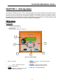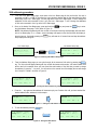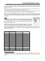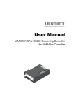
1
VoiceCom System
User Manual
Designed and Manufactured in Australia by
Ampcontrol Pty Limited ACN 000 915 542
Phone: (02) 4956 5899 Fax: (02) 4956 5985
www.ampcontrol.com.au
USER MANUAL
No copies of the information or drawings
within this manual shall be made without the
prior consent of Ampcontrol.
E06397 ISSUE 3 28/09/05
VCA_Manual_Issue_3_E06397_280905.pdf
VOICECOM USER MANUAL ISSUE 3
Copyright Notice
No part of this publication may be
reproduced, transmitted or transcribed into
any language by any means without the
express written permission of Ampcontrol
Pty Ltd, 250 Macquarie Road Warners Bay,
NSW 2282, Australia.
Disclaimer
Ampcontrol Pty Ltd will make no warranties
as to the contents of this documentation
and specifically disclaims any implied
warranties or fitness for any particular
purpose.
Ampcontrol further reserves the right to alter
the specification of the system and/or manual
without obligation to notify any person or
organisation of these changes.
Before You Begin
We would like to take a moment to thank
you for purchasing the VoiceCom
Communication System. To become
completely familiar with this equipment and
to ensure correct operation, we recommend
that you take the time to read this user
manual thoroughly.
CRN: 4820
Software Version 4.0
VOICECOM USER MANUAL ISSUE 3
CHAPTER 1 – OVERVIEW OF THE VOICECOM SYSTEM................................................................................... 4
System highlights ......................................................................................................................................... 4
VCA features................................................................................................................................................ 4
VAA features ................................................................................................................................................ 4
Applications.................................................................................................................................................. 4
The VoiceCom Controller – VCA.................................................................................................................. 5
Key Functions .............................................................................................................................................. 5
Controller Terminals ..................................................................................................................................... 5
PC Software ................................................................................................................................................. 6
Modbus ........................................................................................................................................................ 6
The VoiceCom Amplifier – VAA Overview.................................................................................................... 6
Key Functions .............................................................................................................................................. 6
Keypad ......................................................................................................................................................... 6
Display ......................................................................................................................................................... 6
Local Configuration ...................................................................................................................................... 6
Advanced Battery Management ................................................................................................................... 6
CHAPTER 2 – INSTALLATION .............................................................................................................................. 7
VCA Physical installation.............................................................................................................................. 7
VCA Connections and Wiring....................................................................................................................... 7
Digital Inputs ................................................................................................................................................ 8
Digital Outputs............................................................................................................................................ 10
110VAC Power Inlet and Relay Outputs .................................................................................................... 10
Case Earth ................................................................................................................................................. 10
Data Communication Ports ........................................................................................................................ 11
Communication Line 1 and 2 I.S. Interfaces .............................................................................................. 11
I.S. Keypad Interface.................................................................................................................................. 13
I.S. Audio Interface..................................................................................................................................... 14
I.S. Earth .................................................................................................................................................... 14
VAA Physical Installation............................................................................................................................ 15
VAA Connections and Wiring ..................................................................................................................... 16
CHAPTER 3 - VCA OPERATION ......................................................................................................................... 17
HMI Features ............................................................................................................................................. 17
Front Panel................................................................................................................................................. 17
Display and Main Menu Page .................................................................................................................... 18
Menu System ............................................................................................................................................. 19
Navigation .................................................................................................................................................. 19
Voice Message Information Page – Level 1 ............................................................................................... 19
VCA Message Bank Download Page – Level 1 ......................................................................................... 20
Line Status, VAA Status and Programming Pages – Level 2 and 3........................................................... 20
Line Status Page........................................................................................................................................ 20
VAA Address Setup Page .......................................................................................................................... 21
VAA Status Pages...................................................................................................................................... 23
VAA Operational Status Values ................................................................................................................. 24
VAA User Programmable Settings ............................................................................................................. 24
Setting VAA parameters:............................................................................................................................ 25
Modbus Communication Status – Level 4.................................................................................................. 26
Relay Outputs and Digital I/O – Level 5 ..................................................................................................... 27
Relay Outputs Page ................................................................................................................................... 27
Digital Output Page .................................................................................................................................... 27
Digital Inputs Page ..................................................................................................................................... 28
VCA Configuration – Level 6 ...................................................................................................................... 29
Changing VCA Settings.............................................................................................................................. 32
CHAPTER 4 – VAA OPERATION ........................................................................................................................ 33
VAA Amplifier Module ................................................................................................................................ 33
VAA Features............................................................................................................................................. 33
The LCD..................................................................................................................................................... 34
CONTENTS
VOICECOM USER MANUAL ISSUE 3
Display Messages ...................................................................................................................................... 35
The Keypad................................................................................................................................................ 35
VAA Setup Mode........................................................................................................................................ 35
Enter Setup Mode ...................................................................................................................................... 36
Changing the Settings ................................................................................................................................ 36
VAA Battery Pack....................................................................................................................................... 37
Battery Pack Features:............................................................................................................................... 37
Removing and Connecting Battery Pack from Amplifier Module................................................................ 38
VAA Battery States – Voltage and Charge................................................................................................. 38
Auto-shutoff................................................................................................................................................ 39
Sleep Mode ................................................................................................................................................ 39
Waking the VAA ......................................................................................................................................... 39
Power Supplies .......................................................................................................................................... 39
CHAPTER 5 – PRE-START ALARM OPERATION ............................................................................................. 40
Pre-start Alarm Configuration..................................................................................................................... 40
Initiating a Pre-start Alarm.......................................................................................................................... 40
Verifying the Pre-start Alarm Request Input ............................................................................................... 41
VAA Pre-start Alarm Sounding and Confirmation....................................................................................... 41
Pre-Start Alarm Confirmation ..................................................................................................................... 42
Verifying the Pre-start Alarm While Active ................................................................................................. 42
Verifying the Pre-start Alarm Later ............................................................................................................. 43
Pre-start Alarm Operation Examples.......................................................................................................... 44
Example 1 – a successful pre-start alarm .................................................................................................. 44
Example 2 – a failed pre-start alarm .......................................................................................................... 44
Example 3 .................................................................................................................................................. 45
CHAPTER 6 – CREATING AND DOWNLOADING VOICE MESSAGES ............................................................ 46
Recording and Editing Voice Messages..................................................................................................... 46
VCA Message Bank Editor......................................................................................................................... 46
Voice Message Bank Editor Installation ..................................................................................................... 46
Creating a Message Bank .......................................................................................................................... 47
Downloading and Uploading the Message Bank........................................................................................ 51
Downloading .............................................................................................................................................. 51
Uploading ................................................................................................................................................... 53
CHAPTER 7 – TROUBLESHOOTING.................................................................................................................. 54
APPENDIX A – COMMISSIONING....................................................................................................................... 56
VAA Configuration...................................................................................................................................... 56
Address Setup............................................................................................................................................ 56
Volume, Microphone Gain and Audio Threshold........................................................................................ 57
Charging Current........................................................................................................................................ 57
VCA Line Configuration.............................................................................................................................. 58
Pre-start Alarm Configuration..................................................................................................................... 58
Service Factor ............................................................................................................................................ 58
Pre-Start Warning Tone ............................................................................................................................. 59
Pre-Start OK Current Threshold................................................................................................................. 59
VCA Configuration Record ......................................................................................................................... 60
APPENDIX B – MODBUS..................................................................................................................................... 62
Configuration.............................................................................................................................................. 62
VCA Modbus Read and Write Functions.................................................................................................... 62
Initiating Voice Messages and Voice Message Control.............................................................................. 62
To initiate a voice message:....................................................................................................................... 63
Stopping a voice message: ........................................................................................................................ 63
Message Queuing ...................................................................................................................................... 63
Joining messages together: ....................................................................................................................... 63
Reading VAA Parameters .......................................................................................................................... 63
APPENDIX C – APPLICATION NOTES ............................................................................................................... 65
Communication Line Configurations .......................................................................................................... 65
CONTENTS
VOICECOM USER MANUAL ISSUE 3
Longwall ..................................................................................................................................................... 65
Conveyor.................................................................................................................................................... 65
VAA Only (eg vehicle road, drift, etc) ......................................................................................................... 65
Audio Interface/Audio Barrier ..................................................................................................................... 65
SCADA Displays ........................................................................................................................................ 65
Voice Messages......................................................................................................................................... 65
Loading Voice Messages ........................................................................................................................... 65
APPENDIX D – MENU MAP ................................................................................................................................. 66
APPENDIX E– PARTS LIST ................................................................................................................................. 67
APPENDIX F – SPECIFICATIONS ....................................................................................................................... 68
VCA............................................................................................................................................................ 68
Tones ......................................................................................................................................................... 68
APPENDIX G – I.S. APPROVALS........................................................................................................................ 70
CONTENTS
VOICECOM USER MANUAL ISSUE 3
CHAPTER 1 – Overview of the VoiceCom System
The Ampcontrol designed VoiceCom system is a multi-station audio communication system suitable for long wall and
conveyor message applications. The system’s three principal functions include generating pre-start alarms, playing
pre-recorded voice messages and one to many station communications. The system is comprised of two main
components, the VCA VoiceCom Controller and VAA VoiceCom Amplifier field units.
System highlights
•
•
•
•
•
•
•
•
•
2 Intrinsically Safe communication lines
Connection of up to 31 VAA field units per line
User selectable pre-start alarm tones for each line
Pre-start confirmation from all VAA units
User recordable voice messages – up to 255 messages can be stored
PC software to create voice message banks
High quality audio output
Advanced diagnostic and preventative maintenance features
“Call Exchange” functionality
VCA features
•
•
•
•
•
•
•
•
•
•
•
One compact unit controls pre-start alarms and voice messages
4 line backlit LCD display
Tactile seven button integrated keypad (optional external keypad available)
Easy to use menu system allowing access to system status and configuration pages
16MB flash memory for up to 25 minutes of voice message storage
Monitor and configure VAA field units from VCA
RS-232 interface for downloading voice messages from a PC
RS-485 Modbus interface, allows control of voice messages and reading to system status by a PLC
110VAC operation
Telephone exchange interface
External I.S. keypad interface
VAA features
•
•
•
•
•
•
•
•
•
Intrinsically Safe
IP66 ingress protection rating when enclosed in an Ampcontrol stainless steel housing
Powered using a sealed lead acid battery for high capacity and longer life
LCD display showing operational status values such as line voltage, battery voltage and battery current
Durable 4 button membrane keypad
Dust and moisture protected microphone
Connection for two external speakers
Address, volume, microphone gain and charging current configurable at the VAA as well as at the VCA
Compatible with most existing voice communication systems
Applications
•
•
•
Long wall operations
Conveyors
Hazardous area communication
-4
VOICECOM USER MANUAL ISSUE 3
The VoiceCom Controller – VCA
Key Functions
The Controller’s primary functions are to initiate and confirm pre-start alarms and play pre-recorded voice messages.
The system’s operation can be configured and monitored via the Controller’s easy to navigate menu system. Users
already familiar with Ampcontrol’s Motor Protection and Integrated Protection Relay products may recognise the
menu structure.
Controller Terminals
The Controller has a number of input/output and communication interfaces to suit most applications
•
•
•
•
•
•
•
•
•
12 edge triggered digital inputs for voice message control
2 pre-start alarm initiation digital inputs, one for each communication line
4 digital outputs providing system status indication
4 relay contacts providing pre-start alarm confirmation outputs and system status indication
RS-232 3-wire port for downloading of voice messages
RS-485 3-wire port for Modbus connection to a PLC
2 4-wire communication line terminals (Line 1 and Line 2) including a separate I.S. power supply connection for each
line
2-wire audio interface connection to connect the VoiceCom System to a telephone exchange via an approved barrier
8 inputs for the connection external keypad control buttons and a lock switch (or the VCA Remote Keypad Module)
Figure 1 – VoiceCom system connection diagram
-5
VOICECOM USER MANUAL ISSUE 3
PC Software
The Controller is supplied with the VCA Message Bank Editor Windows PC software. The software enables the user
to create, edit and download voice message banks to the Controller. A separate PC program is required for the
recording of individual voice message audio files before the voice message bank can be created.
Modbus
Most of the Controller’s functionality can be controlled and monitored via a Modbus protocol connection. This
includes playing voice messages and reading VAA operational parameters of all connected VAA units. This Modbus
data can be used for trending via a PLC, allowing for preventative maintenance by giving early indication of cable
failures or VAA batteries that may be ready replacement.
The VoiceCom Amplifier – VAA Overview
Key Functions
The VAA sounds pre-start alarms and amplifies audio signals like voice messages and station-to-station
communication. Unlike other communication systems where pre-start alarm and signalling tones are transmitted via
the audio line, the VAA generates all pre-start alarm tones locally. The VAA has four volume levels and two
microphone gain levels that can be configured, depending on the level of background noise. The VAA also has a
seven level threshold setting that prevents unwanted noise from being amplified.
Keypad
Each of the four VAA keypad buttons also generates a different tone when pressed. The SPEAK button generates a
brief tone when pressed and then a higher pitch tone when released to get the attention of other users. Pressing the
CALL LOCAL button also generates a tone that can also be used to get the attention of other users. The CALL
EXCHANGE button generates a low frequency tone for a short duration that can be used to open telephone circuits.
The FUNC button, when pressed, closes one of the Controller’s digital outputs. This output can be used to trigger an
external event, such as prompting the PLC to initiate certain voice messages.
Display
The LCD display cycles through the VAA’s key operating parameters such as the communication line voltage, battery
voltage, battery current and a system digital communication “heart beat”.
Local Configuration
As well as being configurable from the Controller, the VAA’s programmable settings can also be changed at the VAA
using the unit’s programming mode.
Advanced Battery Management
The VAA’s battery management facility allows the battery’s charging current to be set by the user. The setting of the
battery charging current depends on factors such as the output of the I.S. power supply and the number of VAA units
connected to the communication line. The VAA can effectively disconnect the battery if its voltage falls below a preset level to prevent permanent battery cell damage.
-6
VOICECOM USER MANUAL ISSUE 3
CHAPTER 2 – Installation
This section overs the installation of the VCA and VAA. The various system wiring options are explained as well as
the functions of the VCA and VAA connections. Appendix E lists drawings relevant to the installation and operation of
the VoiceCom system.
VCA Physical installation
The controller can only be installed in the safe area. The required panel cut out is 135mm x 135mm. See drawing
VCOM-A-040 for a panel cut out template with dimensions. To ensure that the installation meets the required IP65
rating, the gasket must be fitted between the controller’s escutcheon and the panel. The controller is supplied with
five mounting brackets each with a M5 x 40mm Phillips head screw. These brackets fitted as shown in Figure 2
below. The fifth bracket is supplied as a spare.
IS EXT KPD IS LINE I/F
COM
COMMS DIGITAL I/O
485 -
0V 2
0V 485
+24V
485 +
DO4
KP8
Audio 2
KP7
Call 2
KP6
-V Line 2
KP5
0V 2
232 TX
DO2
KP4
-V PS2
0V 232
DO1
KP3
DO3
232 RX
LINE 2
DI 0V
PSR2
KP2
KP1
PSR1
AUDIO +
DI12
PSC2
I.S. EARTH
AUDIO -
DI11
DI10
PSC1
DI9
NO2
DI8
LINE 1
NC2
DI7
0V 1
COM2
DI6
NO1
DI5
Audio 1
Call 1
-V Line 1
0V 1
EARTH
-V PS1
NC1
DI4
COM1
DI3
110Vac
DI2
DI1
110Vac
RELAY/PWR
Figure 2 – VCA VoiceCom Controller (E08588) Front, Side and Rear
VCA Connections and Wiring
This section covers VCA terminal functions and wiring. All VCA connections are made at the rear of the VCA unit.
VAA unit wiring can be found later in this manual. The VCA has eight terminal headers and is supplied with seven
terminal plugs. The I.S. Earth terminal is the eighth header and is fixed to the rear of the VCA. There is also a mains
earth connection point, which should not be confused with the I.S. Earth.
The eight terminal headers and case earth are shown in Figure 3. These are:
1
Digital Inputs and Output
6
Line 2 I.S. Communication Line Interface
2
Data Communication (RS-232 and RS-485)
7
I.S. External Keypad Interface
3
110VAC Supply Power and Relay Outputs
8
I.S. Earth
4
Line 1 I.S. Communication Line Interface
9
Case Earth
5
I.S. Audio Interface (for telephone exchange circuit
connection)
-7
VOICECOM USER MANUAL ISSUE 3
6
2
7
IS EXT KPD IS LINE I/F
COMMS
DIGITAL I/O
485 -
COM
0V 2
KP8
Audio 2
KP7
Call 2
KP6
-V Line 2
KP5
0V 2
232 TX
DO2
KP4
-V PS2
0V 232
DO1
232 RX
DI 0V
KP3
0V 485
+24V
485 +
DO4
DO3
LINE 2
PSR2
KP2
KP1
PSR1
AUDIO +
DI12
PSC2
5
I.S. EARTH
8
AUDIO -
DI11
DI10
PSC1
DI9
NO2
DI8
LINE 1
NC2
DI7
0V 1
COM2
DI6
Audio 1
NO1
DI5
Call 1
NC1
DI4
COM1
DI3
110Vac
DI2
110Vac
DI1
-V Line 1
0V 1
EARTH
-V PS1
1
RELAY/PWR
4
3
9
Figure 3 - VCA Connections
Digital Inputs
The controller has 14 digital inputs labelled DI1 to 12, PSR1 and PSR2. A 24VDC supply is required to assert these
inputs. The negative side of this supply is connected to the 0V DI terminal. The positive side of the supply is applied
to the digital input as required.
Inputs 1 to 12 are used for message initiation and are edge triggered. The voice message will not stop when the
24VDC is removed, nor will the message repeat if the 24VDC is held These inputs will remain active for the duration
of the voice message. Inputs PSR1 and PSR2 are used for pre-start alarm initiation and are active for as long as the
input is asserted. The digital inputs can be wired in several configurations depending on the voice message initiation
mode chosen. The connection options are listed in Table 1, Table 2 and Table 3. The three modes are as follows:
1. Digital Inputs/Modbus
In this mode, asserting digital inputs 1 to 12 plays messages 1 to 12 respectively. Messages 13 to 255 are
initiated via the Modbus communication link.
2. Strobe
In this mode all messages, 1 to 255, can be played by setting up the voice message address as an eight bit
binary number using digital inputs 1 to 8 and then using digital input 9 as a strobe to initiate that message.
This allows relay logic to initiate voice messages if no Modbus communication facility is available.
3. Modbus
In this mode all messages, 1 to 255, are played via Modbus. Asserting digital inputs 1 to 12 will not initiate
voice messages.
-8
VOICECOM USER MANUAL ISSUE 3
NOTE: Pre-start alarms cannot be initiated via Modbus. The PSR1 and PSR2 inputs must be used to initiate pre
start alarms on Lines 1 and 2.
Table 1 - Connections for Digital Input/Modbus Mode
Terminal
Function
DI1 to DI12
Momentarily apply +24VDC (edge triggered inputs) to play voice messages 1 to 12
respectively
PSR1
Apply +24VDC to input and hold to play pre-start alarm down line 1
PSR2
Apply +24VDC to input and hold to play pre-start alarm down line 2
0V DI
0V common for all digital inputs (from negative side of 24VDC supply)
Table 2 - Connections for Strobe Mode
Terminal
Function
DI1 to DI8
Set up message address in binary where DI1 is the least significant bit. Apply and
hold +24VDC to the inputs until strobe input has been asserted.
DI9
Momentarily apply +24VDC (edge triggered input) to play the message once the
message address has been set up using inputs DI1 to 8.
DI10 to 12
Not used – no connection
PSR1
Apply +24VDC to input and hold to play pre-start alarm down line 1
PSR2
Apply +24VDC to input and hold to play pre-start alarm down line 2
0V DI
0V common for all digital inputs (from negative side of 24VDC supply)
Table 3 - Connections for Modbus Mode
Terminal
DI1 to DI12
Function
Not used – no connection
PSR1
Apply +24VDC to input and hold to play pre-start alarm down line 1
PSR2
Apply +24VDC to input and hold to play pre-start alarm down line 2
0V DI
0V common for all digital inputs (from negative side of 24VDC supply)
-9
VOICECOM USER MANUAL ISSUE 3
Digital Outputs
The four digital outputs, labelled DO1 to 4, provide indication of system status. These are transistor outputs. The
positive side of a 24VDC supply must be connected to the terminal marked +24V. The negative side of the 24VDC
supply is connected to the input or device to complete the circuit when the output turns on. See the figure below. The
indication provided by these digital outputs can also be read via Modbus. Refer to the Modbus data table in Appendix
B for the location of these digital output flags. However, they can be wired if Modbus communication is not available
or for redundancy. The function of each digital output is as follows:
DO1 – asserted when a “Line Fault” occurs. Line Faults include faults such as the number of VAA communicating
with the VCA being less than or greater than the number of VAAs online setting (VAA # Reply Alarm) or two or more
VAA have the same address (VAA Address Clash). Refer to the VCA Operation and Troubleshooting chapters for
more information on Line Faults.
DO2 – asserted when the “FUNC” button on a VAA is pressed. This output remains on for 5 seconds after the button
is pressed. This could be used to trigger a function such as re-playing are the currently active voice messages.
DO3 – asserted while a voice message is playing. This output can assist the message control device, such as a
PLC, with voice message queuing.
DO4 – this output current has no function.
110VAC Power Inlet and Relay Outputs
The RELAY/PWR header contains the terminations for VCA power supply connection and relay outputs. The
following table describes the functions of the input/output terminals.
CAUTION – ELECTRICAL SHOCK HAZARD
Isolate the 110Vac supply before connecting or disconnecting.
Terminal
110Vac
110Vac
COM1
NC1
NO1
COM2
NC2
NO2
PSC1
PSC1
PSC2
PSC2
Function
Mains supply connection 110VAC 50Hz
Relay 1 common
Relay 1 N/C
Relay 1 N/O
Relay 2 common
Relay 2 N/C
Relay N/O
Relay 3 common
Relay 3 N/O
Relay 4 common
Relay 4 N/O
Energises while the controller is healthy – normally open and normal
closed contacts. De-energises if a VCA or message bank memory fault
occurs. See the Troubleshooting section.
Reserved for future use.
Normally open contact energises when Line 1 pre-start alarm has
successfully sounded – pre-start alarm Line 1 confirmation output
Normally open contact energises when Line 2 pre-start alarm has
successfully sounded – pre-start alarm Line 2 confirmation output
See the Specifications section of this manual for detailed information on the specifications of digital inputs, digital
outputs and relay outputs.
Case Earth
An EARTH connection point is provided adjacent to the 110Vac terminals for the connection of the mains supply
earth.
-10
VOICECOM USER MANUAL ISSUE 3
Data Communication Ports
RS-232 – Message Bank Download
The controller has two data ports. The RS-232 port is used to connect the VCA to a PC for the downloading of the
Voice Message Bank. The Voice Message Bank is a single file that contains all of the pre-recorded voice messages.
This file is compiled and downloaded using the Voice Message Bank Editor PC program provided with the VCA. This
function is normally carried out before the controller is installed and so it is not necessary to wire these terminals.
However, the RS-232 terminals could be wired to a standard female DB9 9-way type socket mounted within the
cubicle for easy connection to a PC via a standard RS-232 9-way serial cable. A ready made serial cable (p/n E09400)
is available from Ampcontrol. A serial cable can also be easily assembled. Figure 4 details the DB 9 pins that are
used for this RS-232 serial cable.
RS-485 – Modbus Communication
The RS-485 port is used to connect the controller to a Modbus capable control or SCADA system. The configuration
of these two ports is described in the Refer to the VCA Operation chapter of this manual for information on how to
configure the communication parameters for this port. Further information on using Modbus can be found in
Appendix B. Table 4, below, lists the data port connections and Figure 4 shows the terminal wiring.
Table 4 - VCA Data Port Connections
Terminal
Function (w.r.t. the VCA)
485 RS-485 negative
0V 485
RS-485 common
485 +
RS-485 positive
No connection
Not used
232 TX
RS-232 transmit
0V 232
RS-232 common
232 RX
RS-232 receive
VCA COMMS
Terminal
Remote
Device
485 –
0V 485
485 +
TxD-/RxDGND
TxD+/RxD+
232 TX
0V 232
232 RX
RxD (DB9 Pin 2)
GND (DB9 Pin 5)
TxD (DB9 Pin 3)
To Modbus Master
Device (RS-485)
To PC Serial COM
Port (RS-232)
Figure 4 - VCA data communication wiring
Communication Line 1 and 2 I.S. Interfaces
Note: Refer to VCA Certificate of Conformity AUS Ex 03.3880X and VAA Certificate of Conformity Aus Ex 03.3881X
for the correct installation and wiring of Intrinsically Safe VCA interfaces.
The controller has two intrinsically safe communication line interfaces, labelled LINE 1 and LINE 2. Each interface
has six terminals: four for connection to the VoiceCom communication line and two for connection to an Intrinsically
Safe power supply. Each line can support a maximum of 31 VAA units, depending on the cable length and power
supply used.
-11
VOICECOM USER MANUAL ISSUE 3
Note: The output parameters of the I.S supply must match the input parameters of the VCA and the VAA. Refer to
VCA Certificate of Conformity AUS Ex 03.3880X and VAA Certificate of Conformity Aus Ex 03.3881X for input
parameters.
The VoiceCom intrinsically safe communication line consists of four cores commonly referred to as: 0V, Audio, Call
(digital communication signals) and –V Line. The 0V and –V Line cores provide voltage for VAA battery charging.
The Audio line carries the system audio signals. The Call line is the digital communication link between the controller
and VAA units. This digital communication line runs the VoiceCom digital protocol, which allows the VCA to retrieve
VAA operating parameters, such as voltage and current values. Table 5
Table 6 list the I.S. communication line interface terminations and Figure 5 shows the terminal wiring for LINE 1. The
wiring for LINE 2 is identical.
NOTE: Each communication line must be powered by a separate I.S. power supply.
Table 5 - LINE 1 Communication Line Interface Connections
Terminal
Function
0V 1
0V supply line 1
Audio 1
Audio line 1
Call 1
Call/digital line 1
-V Line 1
Negative supply line 1
0V 1
I.S. power supply 1 positive input
-V PS1
I.S. power supply 1 negative input
VoiceCom LINE 1
Table 6 - LINE 2 Communication Line Interface Connections
Terminal
Function
0V 2
0V supply line 2
Audio 2
Audio line 2
Call 2
Call/digital line 2
-V Line 2
Negative supply line 2
0V 2
I.S. power supply 2 positive input
-V PS2
I.S. power supply 2 negative input
VAA31
CALL
CALL
E XC HA NGE LOCA L
FU NC.
SP EAK
VAA2
CALL
CALL
E XC HA NGE LOCA L
FU NC.
VoiceCom LINE 2
VAA1
CALL
CALL
E XC HA NGE LOCA L
SP EAK
FU NC.
SP EAK
VCA IS LINE I/F
Terminals
0V 1
Audio 1
Call 1
-V Line 1
0V 1
-V PS1
VoiceCom communication line
Figure 5 - I.S. communication line interface wiring
(LINE 1 shown)
+
–
12VDC – 18VDC
I.S. Power Supply
-12
VOICECOM USER MANUAL ISSUE 3
Note: The I.S. power supply can either be connected to the controller terminals, as shown in Figure 5, or to anywhere
on the communication line to overcome the voltage drop caused by long lines. Refer to VCA approval drawing VCOMZ-036 for I.S. power supply connection options.
I.S. Keypad Interface
The intrinsically safe keypad interface allows an external VCA keypad module (or suitable push buttons) to be installed
in the hazardous area when the VCA is installed in a flameproof enclosure or the VCA keypad is otherwise
inaccessible.
Table 7 shows the I.S. Keypad Interface termination and Figure 6 shows the wiring connections to the VCA Remote
Keypad Module, available from Ampcontrol (p/n E08985). The keypad input functions are self explanatory. Input KP3
is the LOCK input. When the LOCK input is asserted, VCA configuration settings can be changed and Voice
Message Bank files can be downloaded. Opening the LOCK input prevents any settings from being changed. The
LOCK input should be wired to a key lock switch located adjacent to the VCA or behind the panel door.
The keypad inputs are powered from an I.S. power supply. One of the communication line I.S. power supplies can be
used. For further wiring details refer to approval drawing VCOM-Z-036.
Table 7 - I.S. Keypad Interface Connections
Terminal
Function
KP1
UP button
KP2
LEFT button
KP3
Key LOCK (allows access to VCA settings)
KP4
RIGHT button
KP5
DOWN button
KP6
ENTER button
KP7
FUNCTION button
KP8
ESCAPE button
COM
IS power supply common
VCA Remote Keypad
Terminals
12VDC – 18VDC
I.S. Power Supply
+
–
VCA I.S. Keypad
Interface Terminals
COM
KP8
KP7
KP6
KP5
KP4
KP3
KP2
KP1
+V
KP8
KP7
KP6
KP5
KP4
KP2
KP1
i
Figure 6 - I.S. keypad interface wiring to VCA Remote Keypad Module (E08985)
NOTE: The I.S. power supply connected to LINE 1 or LINE 2 can be used to for the VCA I.S. Keypad Interface.
-13
VOICECOM USER MANUAL ISSUE 3
I.S. Audio Interface
The intrinsically safe audio interface allows the VoiceCom System to be connected to a site-wide communication or
telephone network. All audio signals originating from the VoiceCom System such as voice messages and VAA to VAA
communication are output from the audio interface. Likewise, any audio signal input to the interface is broadcast over
the VoiceCom System.
The VoiceCom Audio Barrier (p/n E09441) is required in order to connect the VCA I.S. Audio Interface to an
intrinsically safe communication network. The VoiceCom Audio Barrier provides a number of connection options,
such as allowing two independent VoiceCom communication lines to be connected together. This allows the audio
from one VoiceCom system to be broadcast on the other system and vice versa. Note, however, that this does not
enable a pre-start alarm to sound on the other VoiceCom system or the extension of the digital communication. Refer
to Appendix C for more information on connecting the VoiceCom system to other communication systems.
Table 8 - I.S. Audio Interface Connections
Terminal
Function
AUDIO +
Audio line positive
AUDIO Audio line negative
I.S. Earth
The intrinsically safe earth terminals are used to connect the VCA to a local intrinsically safe earth. The I.S. earth
should be a direct connection and should not be shared with other devises. A minimum of two 4mm2 cores should be
used.
NOTES:
1. Refer to Certificate of Conformity AUS 03.3880X for the correct installation and wiring of Intrinsically Safe
VCA interfaces.
2. The I.S. Earth should not be confused with the VCA Case Earth. These earths should be kept separate.
-14
VOICECOM USER MANUAL ISSUE 3
VAA Physical Installation
The VAA comes in its own stainless steel enclosure. The VAA stainless steel IP66 enclosure includes two speakers
and gland entries (p/n E09100). Other entry configurations can be accommodated. The VAA is also available as a
panel mountable module (p/n E08831) for installation into an existing enclosure or panel door, shown in Figure 8.
See drawing VCOM-A-040 for a panel cut out template with dimensions for the VAA and speakers.
CALL
CALL
EXCHANGE LOCAL
FUNC.
SPEAK
Figure 7 - VAA Speaker Enclosure (p/n E09100)
VAA Front
VAA Side
1
CALL
CALL
EXCHANGE LOCAL
FUNC.
VAA Back
2
SPEAK
5
6
3
4
Figure 8 - VAA module (p/n E08831)
The VAA module consists of the following items:
1
VAA amplifier sub-assembly (p/n E08831)
4
4-way double headed plug for VoiceCom
communication line connection
2
6V 1.2Ahr battery pack (p/n E08584)
5
4 M6 x 20mm Allen head bolts
3
4-way mini plug for speaker connection
6
4 M6 nylon flat washers
NOTE: Only the approved speakers can be connected to the VoiceCom VAA. Two 12 watt, 8 ohm speakers are available as a
separate item (p/n E08783).
-15
VOICECOM USER MANUAL ISSUE 3
VAA Connections and Wiring
The VAA module has three connection headers, as shown in Figure 9 below:
3
2
1
0Volts
Audio
Call
-Vline
Figure 9 - VAA headers and communication line and speaker wiring
1
VoiceCom communication line (4-way)
2
Speakers (4-way)
3
Battery pack (10-way)
The communication line connections are listed in table 9 and speaker connections are listed in table 10 below.Error!
Reference source not found. - VAA communication line connections
Terminal
0V
AUDIO
CALL
-VLINE
Function
0V supply line
Audio line
Call/digital line
Negative supply line
NOTE: The double headed communication line plug provides for separate termination of in and out cables and allows the
communication line plug to be disconnected from the VAA module without breaking the line.
Error! Reference source not found.- VAA speaker connections
Terminal
Function
1+
Speaker 1 positive
1Speaker 1negative
2+
Speaker 2 positive
2Speaker 2 negative
NOTE: The 4-way speaker terminal allows for the connection of two speakers. Wire length between the speakers
and the VAA module should not exceed 300mm. The connection wire must be a minimum of 0.1mm in diameter and
the wire insulation thickness must be a minimum of 0.25mm, as specified in the VAA Certificate of Conformity Aus Ex
03.3881X. Take careful note of the speaker polarity when wiring.
-16
VOICECOM USER MANUAL ISSUE 3
CHAPTER 3 - VCA Operation
The VoiceCom Controller version A, or VCA, as its name suggests, is the master controller of the VoiceCom system.
From the VCA, the VoiceCom system can be easily configured and interrogated. It controls the operation of the prestart alarm and it stores and plays pre-recorded audio messages. The VCA also allows for the VoiceCom system to
be interfaced with a control system such as a PLC, which provides remote monitoring. The VCA’s operation is best
explained by looking at the all of the VCA status and configuration display pages.
HMI Features
Front Panel
The front panel of the VCA includes:
• 4 line, 20 character backlit LCD
• 7 button keypad
• Multicolour indicator LED (green, orange, red)
1
6
2
5
3
4
Figure 10 - VCA Front Panel
1
Display – backlit LCD
4
Key (Function) – used to view last pre-start
alarm operation
2
• •••Keys – navigate through menu
5
Key – used for changing and saving
configuration settings and for menu shortcuts
6
Status LED – VCA status indication
pages and toggle settings
3
Key (Escape) – takes user back to Main
Menu Page and for menu shortcuts
ESC
FUNC
ENTER
-17
VOICECOM USER MANUAL ISSUE 3
2
1
1 VCA4V02 2003 Msg#
Iso at sta 1
13
L1:VAAs Replying OK
L2:No VAAs Enabled
4
5
3
6
Display and Main Menu Page
When power is applied to the VCA the display defaults to the Main Menu page, shown in Figure 11. The backlight will
turn on and remain active for 5 minutes after the last key press. Pressing any of the 7 keys will turn the backlight on.
If not on the Main Menu page, the display will return back to the Main Menu page if no key is pressed for 5 minutes
and the backlight will turn off.
NOTE: The only exception to this is when downloading Message Bank files. The display does not move off of the
VCA Message Bank page when a connection between the VCA and a PC has been established.
1
Menu level number (on all pages)
4
Name of message currently playing
2
VCA Firmware version
5
Line 1 status messages and alarms
3
Number of audio message currently playing
6
Line 2 status messages and alarms
Below are a list of the status and alarm messages that can be displayed for LINE 1 and LINE 2.
Table 9 - VCA Alarm Messages
Figure 11 - Main Menu Page
Message
VAAs Replying OK
VAA Reply # Alarm
Address Clash
No VAAs Enabled
PSW Active
PSW Healthy
PSW Blocked
Description
The number of VAAs that the VCA can communicate with matches the “# of
VAAs to be online” parameter.
The number of VAAs that the VCA can communicate with is greater/less
than the “# of VAAs to be online” parameter.
Two or more VAAs have the same address.
The “# of VAAs to be online” parameter is set to “None”.
A pre-start alarm is active.
The pre-start alarm has been successful. All the required VAAs confirmed
sounding the pre-start alarm.
The maximum pre-start initiation time has been exceeded (30 seconds).
Remove the pre-start alarm input and reapply to sound the pre-start alarm
again. For every second that the pre-start alarm input is removed three
seconds of pre-start alarm can be sounded if the input is reapplied. See the
Pre-Start Alarm Operation chapter for more information on the operation of
the pre-start alarm.
There are also a couple of VCA fault message that can appear on the second line of the display on the Main Menu
page. Refer to the Troubleshooting chapter for more information on VCA faults.
Table 10 - VCA Hardware Fault Alarms
Message
VCA mem. Error
Msg.Proc. Fail
Description
An error has occurred with the VCA configuration memory.
A fault has occurred with the VCA Message Bank hardware.
-18
VOICECOM USER MANUAL ISSUE 3
The tricolour Status LED provides an indication of the health of the VoiceCom system.
•
Green – both communication lines are healthy, no VAA reply alarms or address clashes
•
Orange – a communication line fault exists, such as too few VAAs detected or an address clash
•
Red – a VCA fault exists, such as a VCA memory error or Message Bank processor fault
Menu System
The VCA menu system consists of six menu levels. The menu level number is displayed in the top left corner of all
VCA pages, except for the Voice Message Information page. Each menu level may contain one or a number of
pages. A VCA menu map is provided in Appendix D. These levels are:
1. Main Menu page, Voice Message Information and Download pages
2. LINE 1 Status pages and LINE 1 VAA Programming pages
3. LINE 2 Status pages and LINE 2 VAA Programming pages
4. Mobus Communication page
5. Relay Outputs, Digital Outputs and Inputs pages
6. Configuration pages
Navigation
•
To navigate between menu levels use the•and •keys.
•
To navigate through pages on the same level, use the ••keys. Holding down these keys enables
fast scrolling. This allows menu pages and settings to be scrolled through rapidly with out having to
press the key multiple times.
•
To return back to the Main Menu page press the
ESC
key.
Voice Message Information Page – Level 1
This page is found on menu level one and provides detailed information on a voice message while it is playing. The
page is blank at all other times. It also shows a figure to denote the level of audio detected on the communication
line, as well as a digital communication status indicator.
1
2
Msg#: 1 Time: 1.5 s
Txt:Iso at sta 1
Format :8b-mu 22kS/s
Tone:Pre-0, +End/ 5
3
4
5
7
6
Figure 12 - Voice Message Information Page
1
Number of last message played
5
Pre-tone used with message (see Table 16)
2
Message duration
6
Digital communication status – indicator appears
as a spinning bar
3
Name of last message played
7
Audio level detected on lines
4
Audio format message saved as*
-19
VOICECOM USER MANUAL ISSUE 3
VCA Message Bank Download Page – Level 1
This page shows the PC to VCA communication and Message Bank download status when the VCA is connected to
a PC running the Voice Message Bank Editor program. The display needs to be put on this page in order to
download a voice message bank. The use of this page is described in more detail in the chapter titled “Creating and
Downloading Voice Messages”.
1 VCA Message Bank
* No Msgs Can Play *
Baud Rate:[115k2bps]
Figure 13 - Voice Message Download Page
SHORTCUT: When on this page, pressing the ENTER key will take you to the Message Bank Serial Baud Rate
configuration page from where the RS-232 port’s baud rate can be changed.
Line Status, VAA Status and Programming Pages – Level 2 and 3
Menu level 2 shows status information for communication LINE1 and menu level 3 shows status information for
communication LINE 2. The Line Status Page gives an overall view of the current state of the communications line.
By moving to the left or right on either of these two levels you will find current status for each VAA connected to that
line. VAA address settings configuration pages can also be accessed from these menu levels.
Line Status Page
The Line Status page for LINE 1 is shown in Figure 14 below.
2
4
3
5
1
9
6
2 Line 1 [1] VAA’s/
PSW RQo/o OPo/o IIII
IIIII IIIII ----- 15
----- ----- ----- -
7
8
Figure 14 - Line Status Page
1
Menu level (shown on all pages except those on
menu level 1)
6
Digital comms status – indicator appears as a
spinning bar when digital communication is on
2
Line number (LINE 1 for this display)
7
VAA key press indication
3
Number of VAA’s set to be online
8
VAA address being polled
4
Current state of pre-start 1 request (PSR1)
digital input (o/o = open, o-o = asserted)
9
Representation of communication line showing
VAA’s online
5
Current state of pre-start 1 confirmation (PSC1)
relay output (o/o = open, o-o = closed)
-20
VOICECOM USER MANUAL ISSUE 3
VAAs Online and Clash Indication
The third and forth lines of this display give a semi-graphical representation of the communications line. Each display
character segment represents a VAA address. Address 1 is at the left end of the third line of the display and address
15 is at the right end. Address 16 is at the left end of the forth line and address 31 is at the right end.
•
I symbol represents a VAA that is connected to the line and communicating with the VCA.
•
– character indicates that there is no VAA present at that address.
•
C character indicates an address clash at that address.
Number of VAAs to be Online Value
The top line shows the number of VAA’s that we expect to see online. This value should match the number of VAAs
that are currently installed. This setting is found on menu level 6 and is set at the time of commissioning or whenever
a VAA is added or removed from the line. More information about this setting can be found later in this chapter and in
the Commissioning chapter.
Digital Communication Indicator
While the digital communication protocol is running a spinning bar will appear on the right hand end of the top display
line.
Polling Address Number
While the digital communication protocol is running, the VCA does a ‘round-robin’ scan of every VAA address, 1 to
31. This takes approximately 7 seconds. This number shows which address is currently being scanned and will count
rapidly up through the address range.
Pre-start Request Input and Confirm Output State Indication
The second line of the display shows the current state of the Pre-Start Alarm Request (PSR) digital input and the
Pre-start Confirm (PSC) relay output for this line.
VAA Key Press Indication
There are four I symbols which will appear on the right hand end of the second line, one for each VAA keypad key.
From left to right, these blocks indicate the CALL EXCHANGE key, CALL LOCAL key, FUNC key and SPEAK key.
When a VAA key is pressed, the respective block will appear.
NOTE: If an address clash has existed for several digital round-robin scans, it will take several more scans once the
clash has been rectified before the C symbol disappears from the line display.
SHORTCUT: Pressing the
on menu level 6.
ENTER
key will make the display jump to the # of VAA’s to be online configuration page
VAA Address Setup Page
Each communication line can support up to 31 VAA units, depending on the I.S. power supply used and cable length.
Utilising both VCA communication lines, the system can communicate with 62 VAAs. Each VAA unit is programmed
with a unique address from 1 to 31. The configuration procedure is the same for VAA units connected to LINE 1 or
LINE 2. The addressing process is carried out using the VAA unit’s unique four-digit serial number engraved on the
front fascia.
TIP: During installation the location and serial number of each VAA unit should be noted. A table should be created
with the VAA serial number, location and chosen address. This will speed up the addressing process.
TIP: Addresses should be allocated sequentially, giving the VAA closest to the controller address 1, second closest
address 2 and so forth.
-21
VOICECOM USER MANUAL ISSUE 3
VAA addressing procedure:
1.
From the VCA’s Main Status page, arrow down to the Line Status page for the line that the VAA unit is
connected to (LINE 1 or LINE 2). Note from the menu structure diagram that the first page below the Main
Status page is the Line 1 Status page. The next page down is the Line 2 Status page. To set or change the
addresses of VAA units connected to Line 1 go to the Line 1 Status page. To set or change the addresses
of VAA units connected to Line 2 go to the Line 2 Status page.
2. Once on the desired Line Status page, press and hold the
the VAA Address Setup page. This is shown in Figure 15.
ESC
key and press the
ENTER
key to enter
NOTE: VAA address programming will time out after 10 seconds of inactivity and the display will revert back
to the Line Status page. A ** time out** message will appear on the third line when the display is
about to time out. Continually pressing the FUNC key will reset the 10 second timer and stop the address
setup display from timing out.
Line 1 Status Page
VAA Address Setup Page
2 Line 1 [ 1] VAA’s
PSW RQ o/o OPo/o
----- ----- --------- ----- ----- -
ESC
2 L1 Address Setup
Accept:Ent < [esc] >
+
ENTER
S/n:
0100
Adr [ 1]
Figure 15 - Entering VAA Address Setup Page
3.
From the Address Setup page you can cycle through all the connected VAA units by pressing the ENTER
key. The VAA units will appear starting with the unit with the lowest serial number. VAA serial number 0100
will be used in this example. Once you have found the serial number of the VAA that you want to change
the address of, press the • key once. You will notice on the second line of the display the text will change
from “Accept” to “SetAdr”, as shown in Figure 16.
2 L1 Address Setup
SetAdr:Ent < [esc] >
2 L1 Address Setup
SetAdr:Ent < [esc] >
S/n:
S/n:
0100
Adr [ 1]
0100
Adr [ 1]
Figure 16 – Locating the VAA to address by serial number
4. Press the • key again and the address will increment up by one. Continue this until you have reached the
desired address value, address 4 in this example.
2 L1 Address Setup
Accept:Ent < [esc] >
2 L1 Address Setup
SetAdr:Ent < [esc] >
S/n:
S/n:
0100
Adr [ 1]
0100
Adr [ 4]
Figure 17 - Setting the VAA address value
5. To save the address press the
ENTER
key.
2 L1 Address Setup
SetUp:Ent < [esc] >
2 L1 Address Setup
Accept:Ent < [esc] >
ENTER
S/n:
0100
Adr [ 1]
S/n:
Figure 18 - Saving the VAA address
-22
0100
Adr [ 1]
VOICECOM USER MANUAL ISSUE 3
6. Pressing ENTER again will show the VAA unit with the next highest serial number. Repeat this process until
all the VAA units have been correctly addressed.
7. To leave the Address Setup page at any time press the ESC
2 Line 1 [ 1] VAA’s
key and you will be taken back to the Line Status page. You will
PSW RQ o/o OPo/o
now notice that the appearance of the Line Status page has
I I I I I I I I I I --------- ----- ----- changed. All the VAA units that have had their address set and
are currently online will be represented by a I symbol. The Line 1
Status page on the right shows 10 VAA units online at addresses 1 to 10. The “-” symbol indicates that
there is no VAA unit online at that particular address. A more detail description of this page and the other
menu pages can be found in the VCA Operation chapter of this manual. A C symbol indicates an address
clash. Two or more VAAs may have been programmed with the same address.
Note: New VAA units will be pre-programmed to address 1 by default.
VAA Status Pages
The VAA Status pages are found on the same level as the Line Status page. They are accessed by pressing the ••
keys, as shown in Figure 19.
2 Line 1 [ 1] VAA’s
PSW RQ o/o OPo/o I I
I I I I I I I I --------- ----- ----- -
2 L1 VAA# 1
Vline:16.0V
Vbat: 6.6V
Ibat: 11mA
Sn00100
Thr:[ 3]
Vol:[L3]
Ich:[20]
…
…
2 L1 VAA#31
Vline:--.-V
Vbat: --.-V
Ibat: ---mA
Sn----Thr:[--]
Vol:[--]
Ich:[--]
Figure 19
NOTE: A status page is shown for every VAA address, regardless of whether a VAA is programmed to that address
and communicating with the VCA. The right-most display in Figure 19 shows the status page for address 31. No
parameters appear, indicating that there is no VAA is programmed to this address or this VAA is not communicating
with the VCA.
-23
VOICECOM USER MANUAL ISSUE 3
The VAA Status pages show the current operational status and programmable settings for each VAA connected to
the line. Figure 20 shows the status page for a VAA with serial number 00100 on Line 1, programmed to address 1.
1
5
6
7
2
4
3
2 L1 VAA# 1
Vline:16.0V
V bat: 6.6V
Ibat: 11mA
Sn00100/
Thr:[ 3]
Vol:[L3]
Ich:[20]
11
8
9
10
Figure 20 - VAA Status Page
1
Menu level
7
2
Line number (Line 1 shown here)
8
3
VAA address number (address 1 shown here)
9
4
10
5
VAA serial number (matches number engraved
on VAA)
Line voltage at that VAA
6
VAA battery voltage
11
VAA battery current (positive value indicates charging
current, negative current indicates current being drawn
from battery)
Amplifier threshold setting (user programmable)
Microphone gain and volume setting (user
programmable)
Maximum battery charging current (user
programmable)
Digital communication status – indicator appears as a
spinning bar
VAA Operational Status Values
Vline – this is the line voltage measured at the VAA. The line voltage will depend on the power supply connected
to the line and the distance of the VAA from the power supply.
Vbat – this is the VAA battery voltage. A fully charged battery should show a voltage of 6.6V to 6.7V. A low or
almost fully depleted battery will show a voltage of 5.9V to 6.0V.
Note: The VAA batteries have an over discharge protection feature. If the battery voltage falls below 5.9V, it will shut
itself off to prevent any permanent damage from occuring. The output will only turn on once the battery has received
enough charge to take it above the 6.0V.
Ibat – this is the current going into/coming from the battery. The current will depend on whether the battery is
charging, fully charged or if the VAA’s amplifier is on (due to a PSA, voice message, etc.). A positive value denotes
current used to charge the battery. While charging, this value can read between 5mA to 40mA depending on the
battery charging current setting for the VAA. A negative current value indicates that current is being drawn from the
battery. While sounding a pre-start alarm Ibat can read down to -200mA.When the battery is fully charged and the
VAA is in “standby”, Ibat will be at or near 0mA.
VAA User Programmable Settings
Threshold
The threshold setting determines what level of audio present on the communication line will be amplified by the VAA
unit. The threshold can be set from 0 to 7 where 7 would provide the highest level of noise immunity. A higher
threshold value is used if there is some induced noise on the communications line causing the VAA units to turn on
unintentionally. As well as being a nuisance, VAAs turning on unintentionally can lead to unnecessary battery drain.
-24
VOICECOM USER MANUAL ISSUE 3
Volume and Microphone Gain
The volume and microphone gain are combined into one setting, for example “L3” where L is the gain level and 3 is
the volume level. The volume setting controls the VAA unit’s output volume. The volume can be set to a value from 0
to 3 where 3 is the maximum volume. This applies to voice communication only. Pre-start alarms always sound at a
fixed volume. The VAA unit’s microphone gain is set in conjunction with the volume setting. The gain can be set to
“L” for low or “H” for high. The low gain setting would be appropriate for an environment with a high level of
background noise. The low setting necessitates that the operator speaks close to the VAA and raise his voice. The
high gain is suitable for most other low noise environments. Some simple tests will help to find an appropriate gain
level.
Battery Charging Current
The battery charging current can be set to a value between 5mA and 40mA. As soon as current is drawn from a VAA
battery due to a pre-start alarm, for example, the battery will want to immediately recoup any lost charge. The
battery will take as much current as it has been set to take. Because the current available from the intrinsically safe
power supply is limited, some planning is required when choosing a battery charging current for a particular VAA unit.
If the charging currents are set too high, the VAAs closest to the power supply will take all the current they can
leaving little current for the VAAs furthest away from the power supply. These VAAs may never charge fully. An
example will help to illustrate this.
Example: There are 31 VAAs connected to LINE 1 and a 14VDC 1A I.S. power supply is being used. The battery
charging current of all the VAAs has been set to 40mA. Assuming all the batteries are fully charged, a pre-start alarm
is sounded. As soon as the pre-start alarm stops, all VAAs will try to draw 40mA from the line power supply. The first
20 so VAAs may be able to draw at or near their set charging current, leaving little current left for the last 10 VAAs.
Again, some testing will need to be conducted in order to find the optimum charging currents. Trending VAA battery
voltages and currents over a period of time will help with this. However, 20mA would be a good starting point.
Setting VAA parameters:
1. Go to the VAA Status page of the VAA you wish to program. Press
Figure 21 shows the VAA Status page for the VAA at address 1.
VAA Status Page
ENTER
to enter the VAA Set Up page.
VAA Setup Page
2 L1 VAA # 1
0 100
Vline:12.0V Thr:[ 2]
Vbatt: 6.6V Vol:[L3]
Ibat: 11mA Ich:[20]
2 L1 VAA # 1 Set Up
ENTER
Funct. < ent > [esc]
Bat Chrg.Cur.:[40mA]
Figure 21 - Entering VAA Setup pages
2. Press the •• keys to scroll between the VAA settings: CHARGE CURRENT – MIC GAIN/VOLUME –
THRESHOLD.
To change a setting, press the
ENTER
key and then the press the ••key to decrease or increase the value.
2 L1 VAA # 1 Set Up
2 L1 VAA # 1 Set Up
2 L1 VAA # 1 Set Up
Funct. < ent > [esc]
Bat Chrg.Cur.:[40mA]
Funct. < ent > [esc]
VAA Volume[3], Mic[L]
Funct. < ent > [esc]
Audio Threshold [2]
3. Press the
ENTER
key to save the new value.
-25
VOICECOM USER MANUAL ISSUE 3
Modbus Communication Status – Level 4
The Modbus page is the only menu page on menu level 4, shown in Figure 22. It displays the VCA’s Modbus
communication status. Modbus is the protocol used on the VCA’s RS-485 port to communicate with Modbus capable
control systems such as PLCs. The information given on this page includes indication of Modbus commands
received and any communication errors detected by the VCA.
4 Modbus
Adr[ 1]
Read[ ]
CRC[ ] NF[ ] Wrt.[ ]
Par[ ] FE[ ] Exc.[ ]
Figure 22 - Modbus Status Page
Adr
The Modbus slave address the VCA is set to
CRC
A solid block appears when a checksum error
is detected
Read
A solid block appears when a READ
command is received
Par
A solid block appears when a parity error is
detected
Wrt.
A solid block appears when a WRITE
command is received
NF
A solid block appears when noise is detected
Exc.
A solid block appears when an unsupported
Modbus command is received
FE
A solid block appears when a framing error is
detected
The configuration pages for the Modbus port can be found on menu level 6. On configuration setting allows the baud
rate and parity to set. A second page allows the Modbus slave address to be changed. For more information on
using Modbus, refer to the Modbus Chapter.
SHORTCUT: To change any of the Modbus communication settings, such as baud rate, parity or slave address,
press the ENTER key to view the Modbus configuration settings.
-26
VOICECOM USER MANUAL ISSUE 3
Relay Outputs and Digital I/O – Level 5
The three pages on this menu level show the current state of the VCA’s four relays, four digital outputs and fourteen
digital inputs. These pages are useful for fault finding.
5 Dig IO Information
Relay Outputs
RL-1 RL-2 RL-3 RL-4
In
Out Out Out
1
2
3
4
5
Relay Outputs Page
Figure 23 - Relay Output Status Page
1
Menu level
4
Relay 3 state
2
Relay 1 state
5
Relay 4 state
3
Relay 2 state
In = Energised, Out = De-energised
Relay 1 – VCA hardware healthy. This relay should always be energised while the controller is powered. If a VCA
memory fault or Message Bank processor fault occurs, this relay will de-energise.
Relay 2 – no function
Relay 3 – Pre-start alarm LINE 1 confirmed
Relay 4 – Pre-start alarm LINE 2 confirmed
Digital Output Page
1
5 Dig IO
Lock o/o
Digital Outputs
DO-1 DO-2 DO-3 DO-4
o/o o/o o/o o/o
2
3
4
5
Figure 24 - Digital Outputs Status Page
1
Menu level
4
Digital output 3 state
2
Digital output 1 state
5
Digital output 4 state
3
Digital output 2 state
o/o = unasserted (open), o-o = asserted (closed)
-27
6
VOICECOM USER MANUAL ISSUE 3
DO1 – LINE 1/LINE 2 alarm. This output is unasserted (open) when LINE 1 and LINE 2 are healthy. The output is
asserted if :
•
The number of VAAs the VCA can communicate with does not match the number of VAAs meant
to be online. The VAAs online setting is one of the Configuration pages found on menu level 6.
More information on this setting can be found later in this chapter.
•
There is a VAA address clash. Check the VAA addressing.
DO2 – asserted for 5 seconds when a VAA FUNC key is pressed. This output can be used to trigger an external
event by pressing the FUNC button on any VAA connected to the communication line. This output flag is also available
through Modbus.
DO3 – asserted when a voice message is playing. This output provides a hardwired indication that a voice message
is playing. This output flag is also available through Modbus.
DO4 – no function
3
1
4
5
6
2
5 D-In PS2o/o PS1o/o
1o/o 2o/o 3o/o 4o/o
5o/o 6o/o 7o/o 8o/o
9o/o Ao/o Bo/o Co/o
Digital Inputs Page
1
Menu level
4
Digital Inputs 1, 2, 3 and 4 state
2
PSR1 input state – LINE 1 PSA initiate input
5
Digital Inputs 5, 6, 7 and 8 state
3
PSR2 input state – LINE 2 PSA initiate input
6
Digital Inputs 9, 10, 11 and 12 state (A = DI10, B
= DI11, C = DI12)
o/o = unasserted (open), o-o = asserted (closed)
Figure 25 - Digital Inputs Status Page
-28
VOICECOM USER MANUAL ISSUE 3
VCA Configuration – Level 6
This is the final level of the VCA menu structure. All the user configurable system and line specific settings are found
on this level. Most of these are set during commissioning. Refer to Appendix A for VoiceCom system commissioning
recommendations. The configuration settings in page order are shown in the table below:
Setting
Values
Description
Voice Message
Mode
1. [DI 1-12 + Mbus 13+]
This is the voice message initiation mode
setting and depends on how the system was
installed.
2. [DI 1-8
3. [ Modbus
msg 1-255]
1-255]
1.
The first 12 messages are initiated
directly by asserting digital inputs 1
to 12 and messages 13 to 255 are
initiated via Modbus.
2.
All 255 messages are initiated by
setting the message address in
binary via digital inputs 1 to 8 and
asserting digital input 9 as the
strobe.
3. All 255 messages are initiated via
Modbus
Voice Message
Playback Volume
[ 1] to [10]
This is the master voice message playback
volume, where 1 is low and 10 is high.
Setting the volume too high may cause the
voice messages to sound distorted.
VAA Digital Coms
– Turn off with
Audio
[yes] or [ no]
When set to yes the VoiceCom
communication line digital protocol is
inhibited while audio is detected on the line.
The level of audio needed to turn off the
digital protocol depends on the Audio
Threshold setting. Set this to yes if digital
noise can be heard while messages are
played or during VAA to VAA communication.
VAA Digital Coms –
Turn off Threshold
[ 0] to [ 7]
This is the level of audio that needs to be
detected by the VCA in order for the digital
communication protocol to be inhibited.
Setting this to 0 means that only a small
audio signal will turn off the digital protocol.
Setting this to 7 will mean that a loud audio
signal is required to turn off the digital
protocol.
Line 1 : # of VAA’s
to be online
[ 1] to [31] or [None]
This is the number of VAA’s that are
connected to the LINE 1. This is the number
of VAAs that the VCA should be able to
communicate with.
If no VAAs are
connected, then this is set to None.
Line 1
ServiceFactor #
[0] to [5]
This is the maximum number of VAAs on
LINE 1 that can fail to sound a pre-start
alarm and still allow the pre-start to be
-29
VOICECOM USER MANUAL ISSUE 3
VAA’s offline
successful. A successful pre-start alarm will
close the close relay output PSC1.
Line 1 Pre-start
Warning Tone
[ 0] to [ 7]
Sets the pre-start alarm tone for LINE 1.
There are 8 pre-start alarm tones available.
Line 1 Pre-Start
OK I Threshold
[ 30mA] to [180mA] in 10mA steps
This sets the minimum current that must be
drawn by a VAA from its battery on LINE 1
in order for the VAA to confirm that it has
sounded the pre-start alarm. This can be set
to such a level as to indicate that one of the
VAA’s two speakers has failed. See the PreStart Alarm chapter for more information
Line 1 Under
Voltage Alarm
Level
[ None]
This feature is not implemented in this
version of the VCA hardware and therefore
cannot be set.
Line 2 : Number of
VAA’s to be
Online
[ 1] to [31] or [None]
This is the number of VAA’s that are
connected to the LINE 2. This is the number
of VAAs that the VCA should be able to
communicate with.
If no VAAs are
connected, then this is set to None.
Line 2 Service
Factor
[0] to [5]
This is the maximum number of VAAs on
LINE 2 that can fail to sound a pre-start alarm
and still allow the pre-start to be successful.
A successful pre-start alarm will close the
close relay output PSC1.
Line 2 Pre-start
Warning Tone
[ 0] to [ 7]
Sets the pre-start alarm tone for LINE 2.
There are 8 pre-start alarm tones available.
Line 2 Pre-start
OK Current
Threshold
[ 30mA] to [180mA] in 10mA steps
This sets the minimum current that must be
drawn by a VAA from its battery on LINE 2
in order for the VAA to confirm that it has
sounded the pre-start alarm. This can be set
to such a level as to indicate that one of the
VAA’s two speakers has failed. See the PreStart Alarm chapter for more information
Line 2 Under
Voltage Alarm
Level
[ None]
This feature is not implemented in this
version of the VCA hardware and therefore
cannot be set.
Modbus
Communication
Baud Rate and
Parity
[1200 Baud,Even/Odd/No
Par]
This set the communication parameters for
the Modbus RS-485 port. There are 5 baud
rates and the parity can be set for each
baud rate.
[2400 Baud,Even/Odd/No
Par]
[4800 Baud,Even/Odd/No
Par]
[9600 Baud,Even/Odd/No
Par]
[19k2 Baud,Even/Odd/No
Par]
Modbus
Communication
[ 1] to [31]
This sets the VCA’s Modbus slave address.
-30
VOICECOM USER MANUAL ISSUE 3
Slave Address
Message Bank
Serial Baud Rate
[ 28k8bps]
This sets the baud rate of the VCA to PC
connection using the RS-232 port for the
downloading of Message Banks. All other
communication parameters are fixed as the
RS-232 port is only connected to a PC
running the Voice Message Bank Editor
program.
[ 57k6bps]
[115k2bps]
[230k4bps]
-31
VOICECOM USER MANUAL ISSUE 3
Changing VCA Settings
The procedure for changing a setting on menu level 6 is the same for all settings. The procedure explains how to change VCA
configuration settings using the Voice Message Playback Volume setting as an example.
NOTE: The Key Lock input must be asserted in order for any settings to be changed.
1
Go to the setting you wish to change. For this example the Voice Message
Playback Volume will be changed from 5 to 7.
6 VCA Configuration
Voice
Message
Playback Volume:[ 5]
2
Press the ENTER key to enter the setting edit mode. The second line of the
display will display the text:
<-
ent
->
6 VCA Configuration
<- ent -> [esc]
Voice
Message
Playback Volume:[ 7]
[esc]
The value that appears in the [ ] can now be changed. Pressing the ESC
key will take the display out of the setting edit mode and any changes will not be
saved.
3
6 VCA Configuration
Use the
4
5
<- ent -> [esc]
Voice
Message
•• keys to change the value as required.
Playback Volume:[ 5]
Press the ENTER key again to save the setting. The second line of the display
will show:
Saving Value ->->->->
6 VCA Configuration
Saving Value ->->->
Voice
Message
Playback Volume:[ 7]
for a brief moment while the setting is saved.
Once the new value has been saved the display will go return to its normal state.
6 VCA Configuration
Voice
Message
Playback Volume:[ 7]
-32
VOICECOM USER MANUAL ISSUE 3
CHAPTER 4 – VAA Operation
The VoiceCom Amplifier version A, or VAA, is the field communications unit of the VoiceCom system. It consists of
two parts:
1. VAA amplifier module
2. VAA battery pack
2
1
NOTE: The battery pack must be connected to the VAA amplifier module in order for the VAA to function.
Figure 26 - Amplifier Module with Battery Pack
VAA Amplifier Module
VAA Features
1
8 character LCD
5
Speaker connection header for two speakers
2
Sealed microphone
6
Battery pack connection header
3
4 key membrane keypad
7
Communication line connection header
4
VAA serial number
1
2
3
4
5
Figure 27 - VAA Amplifier Module Front and Back
-33
6
7
VOICECOM USER MANUAL ISSUE 3
The LCD
L-U 12.0
---
1
2
4
3
1
VAA operational parameters (cycles between 3
L-U = line volts, B-U = battery volts and B-I =
battery current)
Digital comms heartbeat status indicator bar
2
Amplifier on status indicator bar
VAA data polling indicator bar
4
Display Cycle
The display shows the VAA’s current operational parameters and status. The display shows line voltage (L-U),
battery voltage (B-U) and battery current in milliamps (B-I). The display continuously cycles through these three
operational values in the order shown in Figure 28. B-I, the battery current does appear twice in each cycle.
LINE VOLTS
BATTERY CURRENT
BATTERY VOLTS
BATTERY CURRENT
Figure 28 - VAA Display Cycle
Display Segments
The VAA display also has three horizontal segments that are very useful in fault finding. From left to right these
segments are:
•
VAA amplifier on
While the VAA’s amplifier circuit is enabled, this segment will remain on. The amplifier circuit is enabled
when the VAA amplifies a sound through its speakers.
•
Digital communication heartbeat
When a VAA is connected to a healthy VoiceCom communication line with a VCA, the digital communication
heartbeat segment will flash. This indicates that the VAA is sensing the digital line protocol.
•
VAA data poll
The VCA does a ‘round robin’ scan of all 31 VAA addresses that takes approximately 7 seconds. Every
address is polled regardless of whether a VAA is programmed to that address or not. Every time a VAA is
polled this segment will flash. Viewing a VAA’s status page from the VCA will cause that VAA to be polled
more often.
NOTE: VAAs with version 1 firmware do not have these status segments.
-34
VOICECOM USER MANUAL ISSUE 3
Display Messages
Table 11 - VAA Display Messages
CLASH
An address clash exists. Check that all VAAs have been programmed with a unique
address.
PS ----
When the VCA initiates a pre-start alarm PSW ---- is displayed on the VAA.
The display will alternate between this message and the battery current being
drawn from the battery. If the VAA does not draw more than the Pre-Start OK Current
Threshold set at the VCA, this message will be displayed until the pre-start alarm
stops.
B-I -180
PS PASS
If the VAA draws more than the Pre-Start OK Current Threshold set at the VCA
then PSW PASS is displayed on the VAA for the duration of the pre-start alarm.
The Keypad
The four buttons on the VAA keypad are SPEAK, FUNC, CALL LOCAL and CALL EXCHANGE.
•
SPEAK
Press the Speak button to communicate with another user. This voice communication will be broadcast on
all VAAs connected to both communication lines. When pressed, a brief, low frequency tone (752Hz) is
generated, which is used to get the attention of other users. When the SPEAK button is released, a second,
brief tone (1002Hz) is heard, higher in frequency than the first to indicate that speaker has ended his
broadcast. The display shows the text SPEACH while the button is pressed.
NOTE: The microphone has been designed to reduce the pick up of background noise. It is therefore
necessary to speak as close as possible to the microphone.
•
FUNC
The FUNC (Function) button, when pressed, causes the VCA to set a flag in the Modbus data table and
asserts digital output DO2 for a period of 5 seconds. This flag and output can be used to trigger an external
event, such as making the PLC play all the active system messages. A brief tone is generated when this
button is pressed and is only heard locally at that VAA. The display shows the text FunC while the button is
pressed.
•
CALL LOCAL
The Call Local button causes the VAA to generate a (848Hz) tone while being pressed. This tone is heard at
that VAA and across the whole system. It can be used for signalling other users. The display shows the text
CALL Lo while the button is pressed.
•
CALL EXCHANGE
The Call Exchange button, when pressed, causes the VAA to generate a 5 second low (200Hz) tone. If the
VoiceCom system is connected to telephone pair, this tone can be used to open a voice circuit for
communication with the surface. The display shows the text CALL EH while the button is pressed.
VAA Setup Mode
The VAA Setup Mode allows the VAA’s user programmable settings to be changed locally at the VAA unit. The VCA
Operation chapter describes how to program all VAA settings from the VCA. Being able to program these settings
from the VAA means that a VAA can be correctly set up when it is connected to the communication line, without
needing to go to the VCA. These settings are:
-35
VOICECOM USER MANUAL ISSUE 3
•
•
•
•
VAA operating mode
Local volume
Threshold
Battery charging current
•
VAA address
Enter Setup Mode
A special key sequence is required to enter the VAA setup mode. Some practice may be required. To enter Setup
mode follow the procedure below:
1
Press and hold the VAA’s SPEAK and FUNC buttons at the same time.
2
After a few seconds the VAA unit’s LCD display will show the text
SETUP F. The F will begin to flash slowly, disappearing for one second,
appearing for one second, disappearing again for one second and then
appearing again for one second. Press and release the FUNC key in
sequence with the flashing F. Release the FUNC button when the F
disappears and press the FUNC button when the F reappears.
SPEAK
SETUP
F
NOTE: The SPEAK button must remain pressed.
3
If the correlation between the button presses and the flashing F is close
enough, access to Setup mode is granted. The display will briefly show
the VAA firmware version before displaying the first VAA setting. The
SPEAK and FUNC buttons can then be released.
VAA V4
NOTE: The VAA display will quit out of Setup Mode if no keys are pressed for 5 seconds and any changes will not be
saved. Continually pressing the CALL EXCHANGE button will reset the timer and will keep the VAA in Setup Mode.
Changing the Settings
1. Press the CALL EXCHANGE button to scroll through the 5
settings.
2. Press the FUNC button to increase the value or the CALL
LOCAL button to decrease the value.
3. NOTE: The Setup Mode will time out if there are no key presses
for 5 seconds.
4. Press the SPEAK button to save the new settings. If the VAA
times out of set up mode, any changes will not be saved.
-36
MODE
CALL
EXCHANGE
VOLUME
THRESHOLD
CHARGE CURRENT
ADDRESS
VOICECOM USER MANUAL ISSUE 3
Table 12 - VAA Programmable Settings
Display
Meaning
Values
Description
MD
VAA Mode
VCA or ---
If connected to a VoiceCom system this setting should
be set to VCA. If set to --- the VAA will not respond
to VCA digital communication polling and will not
appear online.
VOL
Volume/Gain
L0 to L3 and H0 to The L/H sets the sensitivity level and the number, 0
to 3, sets the volume level. In areas of high
H3
background noise set the sensitivity to L (Low). This
requires the use to speak in a louder tone, closer to
the microphone Otherwise set the sensitivity to H
(High).
THRS
Threshold
0 to 7
The threshold sets the audio level on the
communication required to turn the amplifier on and
sound from the speakers. 0 is the lowest level, where
by only a very low level of audio will turn on the
amplifier. 7 is the highest level.
ICHG
Charging Current
5 to 40 (in mA)
The charging current setting is the amount of current
the VAA will draw from the communication line to
charge its battery. The charging current requires
careful consideration as it depends on the output of
the I.S. power supply used, the number of VAAs
connected to the communication line and distance of
the VAA from the power supply.
ADDR
VAA Address
1 to 31
Only 31 VAAs can be connected to each
communication line and each VAA is given a unique
address. Setting two VAAs to the same address will
cause an address clash
VAA Battery Pack
Battery Pack Features:
•
6V 1.2Ah Sealed Lead Acid (SLA) battery
•
Integrated battery charging circuit
•
19Vdc to 11Vdc I.S. supply input for battery charging
•
6.8V to 5.9V output to VAA
•
Auto-shutoff (over discharge protection)
•
‘Sleep’ mode for storage
-37
VOICECOM USER MANUAL ISSUE 3
Removing and Connecting Battery Pack from Amplifier Module
Removing
1. Unscrew the two captive, allen head battery pack retaining screws using a 2.5mm hex head tool.
2. Gently pull the battery pack away from the amplifier module at the 10-way connector to disconnect the
battery pack. The battery pack’s ‘securing hooks’ will bend slightly.
3. Slide the securing hooks from the mounting points on the top of the amplifier module.
Connecting
1. Slide the battery pack securing hooks on to the mounting points on the top of the amplifier module so that
they are clasped securely.
2. Gently press the battery pack connector into the header on the back of the amplifier module.
3. Screw the the two captive, allen head battery pack retaining screws using a 2.5mm hex head tool.
VAA Battery States – Voltage and Charge
Table 13 - VAA Battery States
Battery Voltage
Battery Current
Fully Charged
6.3V to 6.8V
0mA (+/-3mA)
Charging
5.9V to 6.8V
Up to set charging current
Low Charge
5.9V to 6.1V
n/a
NOTE: If the charging current setting is set to 40mA the battery will take up to 40mA, approximately. This will depend
on how much current the communication line can provide.
-38
VOICECOM USER MANUAL ISSUE 3
Auto-shutoff
If the battery voltage falls below 5.9V, it will shut down its output to prevent causing permanent damage to the SLA
battery cells. This will occur if there is insufficient charging current available from the communication line.
Sleep Mode
The battery pack can be put to ‘sleep’ to conserve battery charge and protect the battery cells from damage. Putting
the battery pack to sleep forces its output to shut down. The battery pack should be put to sleep if the communication
line power supply is not available i.e. when the VAA is not connected to the communication line.
To put the VAA to sleep:
1. Disconnect the VAA from the VoiceCom communication line
2. Momentarily connect a piece of wire between terminals 1 and 6 of the battery pack header, as shown in
Figure 29. A piece of wire can either be inserted in the holes on top of the header or into the socket holes.
3. The VAA display will go blank when the battery has shut down.
4. Remove the wire from the header.
wire
6
1
Figure 29 - Putting the VAA to Sleep
Waking the VAA
To ‘wake’ up a VAA that has shut down, connect the VAA to a VoiceCom communication line with a power supply
voltage greater than 11Vdc.
•
A VAA that has been put to sleep and has enough charge will wake up straight away.
•
A VAA that has shut down due to low charge will have to be connected to a communication and recoup
enough charge. The VAA will not wake up until the battery voltage has risen above 6.0V. This may take
several hours depending on how depleted the battery charge is.
If the VAA does not wake up, the battery back may have become damaged. Refer to the Troubleshooting chapter for
more information on fault finding VAAs.
Power Supplies
Only connect the VAA to an I.S. power supply with output parameters that match the VAA input parameters, as
outlined in Certificate of Conformity Aus Ex 03.3881X.
-39
VOICECOM USER MANUAL ISSUE 3
CHAPTER 5 – Pre-Start Alarm Operation
There are four aspects to the pre-start alarm operation:
1. Pre-start alarm configuration
2. VCA initiating a pre-start alarm
3. VAAs sounding and confirming the pre-start alarm
4. VCA determining if pre-start alarm operation is successful
Pre-start Alarm Configuration
There are four VCA settings that affect the operation of the pre-start alarm. These are:
•
# of VAA’s to be online
•
ServiceFactor # VAA’s offline
•
Pre-start Warning Tone
•
Pre-Start OK I Threshold
The configuration of these settings is explained in more detail in the VCA Operation chapter and in Appendix B of this
manual. If both communication lines are being used, these settings must be configured individually for each line.
Initiating a Pre-start Alarm
1.
A pre-start alarm is initiated by asserting Pre-Start Request digital input, PSR1, for LINE 1 or PSR2 for LINE 2
on the VCA. These inputs need to be held on for the length of pre-start alarm required. The VCA will display the
text PSW Active on the Main Menu page. Refer to the Installation and Wiring chapter for more detailed
information on using the digital inputs.
NOTE: Pre-start alarms cannot be initiated via Modbus.
2.
When a pre-start alarm is initiated for a particular line, the VCA sends the pre-start alarm command down that
line using the digital communication protocol. The command includes the following information:
•
Pre-start alarm tone to sound (tones 0 to 7 – depends on configuration)
•
Pre-start minimum current draw threshold (depends on configuration)
3. The pre-start alarm will sound on top of any voice messages being played or VAA to VAA communication.
4.
The pre-start alarm will sound for as long as the respective digital input is held high. It sounded be sounded for
at least 6 seconds, which is the time it can take for the VAAs to confirm sounding the alarm. The VCA will allow a
pre-start alarm to sound for a maximum of 30 seconds. After which time the pre-start alarm will be blocked. The
VCA will display the text PSW Blocked on the Main Menu page.
5.
To sound the pre-start alarm again, the input must be removed and then reapplied. For every one second that
the pre-start alarm request input is removed, three seconds of alarm sounding time become available. If the
input is removed for 10 seconds, a full 30 second pre-start alarm can be sounded. This feature has been
incorporated to prevent the VAA batteries from being run down by a pre-start sounding for an indefinite period if
the pre-start input or the device driving the input fails.
-40
VOICECOM USER MANUAL ISSUE 3
Verifying the Pre-start Alarm Request Input
For troubleshoot purposes, the PSR1 and PSR2 digital input states can be verified by looking at the Line Status page
for the desired line or the Digital Inputs page. Figure 30 below shows that the PSR1 input, the pre-start request input
for LINE 1, is being asserted, as indicated by the o-o graphic.
2 Line 1 [12] VAA’s
PSW RQ o-o OPo/o
I I I I I I I I I I --------I ----- ----- I
PSR1 digital
input state
5 D-In PS2o/o PS1o-o
1o/o 2o/o 3o/o 4o/o
5o/o 6o/o 7o/o 8o/o
9o/o Ao/o Bo/o Co/o
Figure 30 - Verifying the PSR Input
VAA Pre-start Alarm Sounding and Confirmation
1. All connected VAAs will receive the pre-start command and necessary parameters from the VCA.
2. The alarm tones are generated locally by each VAA, not by VCA. The tone sounded depends on the pre-start
tone set for that line at the VCA.
3. While the VAA sounds the alarm, its display will alternate between showing the text PS ---- and the current
being drawn from the battery. The “----” indicate that the alarm has not yet been confirmed for that VAA.
4. During this time, the VAA measures the current being drawn from the battery and compares this value with the
current threshold level it is receiving from the VCA. A VAA will typically draw anywhere between 140mA to
180mA with two speakers connected. If one speaker fails, the current drawn will be approximately half the two
speaker value. If both speakers fail, the current will only be a few mA.
a.
If the current being drawn from the battery exceeds the current threshold level then the pre-start
alarm has successfully sounded at the VAA. The VAA display will alternate between showing the
text PS PASS and the battery current. The VAA will send this confirmation back to the VCA.
b.
If the current being drawn from the battery is less than the current threshold level then the pre-start
alarm has failed at the VAA. The VAA may have still sounded the alarm. The VAA display will
alternate between showing the text PS ---- and the battery current. The VAA will not send
confirmation back to the VCA.
5. The current shown on the VAA display during a pre-start will help to understand why a VAA is not confirming a
pre-start alarm.
NOTE: Each pre-start alarm tone, while sounding, may draw a different amount of current. Some testing will have to
be conducted to find a suitable current threshold leve.
-41
VOICECOM USER MANUAL ISSUE 3
Pre-Start Alarm Confirmation
If a pre-start alarm is successful the confirmation relay output will close. PSC1 is the pre-start confirmation output for
LINE 1 and PSC2 is the pre-start confirmation output for LINE 2. However, a pre-start alarm is successful if the
correct number of VAAs sound the alarm. This depends on:
•
The number of VAA supposed to be online (# of VAA’s to be online setting)
•
The number of VAAs that confirm sounding the pre-start alarm
•
The Service Factor (ServiceFactor # VAA’s offline setting)
The number of VAAs to be online setting should be set to the number of VAAs that that been installed on the
respective communication line, LINE 1 or LINE 2. The Service Factor allows for some of these VAAs (up to 5) to fail
to confirm sounding the pre-start alarm and still allow the confirm relay output to close.
1. The VCA receives confirmation from the VAAs.
2.
The minimum confirmations the VCA must receive equals the number of VAAs supposed to be online minus
the Service Factor (min confirmations = # VAA’s to be online – ServiceFactor # VAA’s offline).
a.
If the number of VAA confirmations received by the VCA is greater than or equal to the minimum
confirmations value, the pre-start alarm is successful. The VCA Main Menu page will display the
text PSW Healthy. The confirm relay (PSC1 or PSC2) will close.
b.
If the number of VAA confirmations received by the VCA is less than the minimum confirmations
value, the pre-start alarm has failed. The VCA Main Menu page will display the text PSW
Active until the pre-start request input is removed or the pre-start is blocked. The confirm relay
(PSC1 or PSC2) will not close.
Verifying the Pre-start Alarm While Active
Verifying the pre-start alarm operation is best done from the Line Status page for the line sounding the alarm. When
a pre-start alarm is active it is possible to see exactly which VAAs have given confirmation and which ones have
failed. This page also shows that state of the confirm relay for that line. This process is illustrated in Table 14.
1. On the Line Status page, a I indicates that a VAA is online at that address.
2.
When a pre-start alarm is initiated, the I symbol turns to an o for all 31 of the VAA addresses. This o remains
on the display until the confirmations are received.
3.
When the VCA receives the confirmations from all or most of the VAAs, the o turns to either an X or a P. The P
indicating that that VAA has confirmed sound the alarm and the X indicating that it has not. This display remains
while the pre-start input is asserted. Once the pre-start alarm input is de-asserted the Line Status display reverts
back to showing the solid blocks representing each VAA.
-42
VOICECOM USER MANUAL ISSUE 3
1
Line Status page showing 20 VAAs on LINE 1, at
addresses 1 to 20, before the pre-start is initiated.
2 Line 1 [20] VAA’s
PSW RQo/o OPo/o
IIIII IIIII IIIII
IIIII
----- -----
2
The pre-start alarm is initiated, but no VAA
confirmations have been received. Note that the
request input is closed, as shown by the RQo-o
graphic.
2 Line 1 [20] VAA’s
PSW RQo-o OPo/o
ooooo ooooo ooooo
ooooo ----- ----- -
3
The confirmations have been received. 19 of the 20
VAAs have confirmed, with the VAA at address 8
indicating a failure. The confirmation relay has closed
as indicated by the OPo-o graphic. But one failure
was detected, so why has the confirmation output
closed? The Service Factor was set to a value of one
or greater, allowing the system to tolerate the VAA at
address 8 failing.
2 Line 1 [20] VAA’s
PSW RQo-o OPo-o
PPPPP PPXPP PPPPP
PPPPP ----- ----- -
-
Table 14 - PSA Confirmation Process
Verifying the Pre-start Alarm Later
From the Line Status page, the outcome of the last pre-start alarm operation can be viewed for fault finding
purposes.
1. Pressing the
failed.
FUNC
2. Press and hold the
key will show which VAAs confirmed, however it does not explicitly show which VAAs
FUNC
key. The I symbol will change into either a P or a –.
3. If the I changes to a P, this indicates that that VAA confirmed sounding the last pre-start alarm. If the I turn to
a –, this indicates that that VAA failed to sound the pre-start alarm correctly.
NOTE: Pre-start alarm operational data, as described above, can be read via Modbus. Refer to the Modbus chapter
for more information.
-43
VOICECOM USER MANUAL ISSUE 3
Pre-start Alarm Operation Examples
Example 1 – a successful pre-start alarm
The system:
• VAAs connected: 20
• # of VAA’s to be online: 20
• ServiceFactor # VAA’s offline: 0
2 Line 1 [20] VAA’s
PSW RQo/o OPo/o
IIIII IIIII IIIII
I I I I I ----- -----
1. Figure 31 shows the Line Status page before the pre-start
alarm is initiated.
2. A pre-start alarm is initiated on LINE 1 by asserting the
PSR1 digital input as indicated by the RQo-o graphic.
3.
Once all of the VAA confirmations have been received, the
Line Status page will then appear shown in Figure 32. It can
be seen that all 20 VAA units have confirmed as indicated by
the P’s, each representing confirming VAA.
-
Figure 31
2 Line 1 [20] VAA’s
PSW RQo-o OPo-o
PPPPP PPPPP PPPPP
PPPPP ----- ----- Figure 32
4. The OPo-o graphic indicates that the pre-start confirm relay is energised because the pre-start alarm has
sounded successfully.
Example 2 – a failed pre-start alarm
The system:
• VAAs connected: 20
• # of VAA’s to be online: 20
• ServiceFactor # VAA’s offline: 0
1. The settings are kept the same as example 1.
2.
Figure 33 shows how the Line Status page once all the
confirmations have been received. Note the two X symbols,
indicating that VAAs at addresses 7 and 20 failed to confirm
the pre-start alarm.
2 Line 1 [20] VAA’s
PSW RQo-o OPo/o
PPPPP PXPPP PPPPP
PPPPX ----- ----- -
3. The confirmation output will not close, OPo/o, because two
Figure 33
VAA failures have been detected. The Service Factor is set to
0; therefore the system will not tolerate any failed VAAs. Setting the Service Factor to 2 would have made this
pre-start alarm operation successful.
-44
VOICECOM USER MANUAL ISSUE 3
Example 3
The system:
• VAAs connected: 20
• # of VAA’s to be online: 20
• ServiceFactor # VAA’s offline: 3
1. For this example the Service Factor is set to 3.
2.
Figure 34 shows how the Line Status page once all the
confirmations have been received. Note the three X symbols,
indicating that VAAs at addresses 7, 15 and 20 failed to
confirm that they have sounded a pre-start alarm.
3. Because the Service Factor is set to 3, we can tolerate up to
three VAA failures.
2 Line 1 [20] VAA’s
PSW RQo-o OPo-o
PPPPP PXPPP PPPPX
PPPPX ----- ----- Figure 34
4. The OPo-o graphic indicates that the pre-start confirm relay is energised because the pre-start alarm has
sounded successfully.
5. Once the pre-start alarm input has been removed, the Line Status page will revert back to its normal display,
showing a solid block for each VAA online.
6. To view which VAAs confirmed sounding an alarm during the
last pre-start, press and hold the FUNC key. The Line Status
page is shown in Figure 35
Note that the VAAs that failed to confirm are not explicitly shown.
Only the units that confirmed, as indicated by the P, are shown.
When the FUNC key is pressed, any I symbols that change to –
symbols can be assumed to have failed during the last pre-start alarm.
-45
2 Line 1 [20] VAA’s
PSW RQo-o OPo-o
PPPPP P-PPP PPPPPPPP- ----- ----- Figure 35
VOICECOM USER MANUAL ISSUE 3
CHAPTER 6 – Creating And Downloading Voice
Messages
The VCA Controller has the capability of storing and playing up to 255 individual, pre-recorded voice messages. These
messages are created in the easy steps:
1. Record and edit the voice message sound files on a PC.
2. Create the Voice Message Bank using the Ampcontrol Voice Message Bank Editor PC program provided.
3. Download the message bank into the VCA.
Recording and Editing Voice Messages
The voice messages can be recorded using a PC with a sound card or similar audio input/output hardware. A myriad
of PC programs are available that can record and edit sound files. The main requirement is that program has the
facility to save audio files as 16bit 44kHz WAV audio files, which most do. We have successfully used a PC program
called “GoldWave”, which has a comprehensive set of audio recording and editing features. GoldWave can be
downloaded from on of the many internet shareware and freeware download web sites. Refer to your PC manuals for
information on setting up audio hardware.
The procedure for recording and editing voice messages will vary depending on the audio editing application chosen.
However, below are some tips that may help with this process:
•
Decide on the voice messages required for the specific installation and produce a printed script with the text of
the voice messages.
•
Instead of recording and saving one message at a time, record several message at once with a pause in
between each message. Many audio editors will let the user to easy cut portions of a recording and save them
as individual files.
•
This might seem obvious, but try to conduct the recording session in as quiet an environment as possible. Many
microphones are sensitive enough to pick up noise from the air-conditioning, PC fans and disk drives.
•
If possible, select a voice that is clear sounding (female voices seem to get the most attention).
•
When editing try to trim as much silence from either end of the message sample as possible. This will eliminate
any unnecessary pauses when messages are played.
•
Maximise (amplify) the samples as much as possible without introducing distortion and compromising sound
quality. A combination of audio compression and amplification can be employed to produce high volume, even
sounding messages. The louder message samples are the louder they will play on the VoiceCom system.
•
Always save WAV audio files at 16bit 44kHz. Most audio recording programs will allow this. The VCA Message
Bank Editor has the facility to down sample files if required. Higher sampling rates produce better sounding
messages. VCA Message Bank storage space permitting, voice messages should be set to the highest quality
format (resolution and sampling rate) possible. The audio format setting is explained later in this chapter.
VCA Message Bank Editor
The next step is to build the voice message bank. This is done using the VoiceCom VCA Message Bank Editor PC
software provided with the VCA Controller. The VCA Message Bank Editor is a software program for Windows PCs.
It allows the creation, configuration and downloading of voice message banks. A voice message bank is a single file
that encapsulates all of the pre-recorded voice messages and associated parameters such as message address,
audio format and pre-tone number.
Voice Message Bank Editor Installation
The VCA Message Bank Editor consists of a standalone executable (.exe) file, that can be installed anywhere in the
PC’s file system. When run for the first time, the program will create a settings file with the extension “.ini” in the
same folder as the executable file. No other installation or configuration is required
-46
VOICECOM USER MANUAL ISSUE 3
Creating a Message Bank
Starting the Editor
1. To start the editor, double click on the VCA Message Bank Editor executable file. A title window will appear for a
moment showing the software version number as the program starts up. The main editor window, as shown in
Figure 36, will appear.
2.
Like most Windows applications the editor window has a menu bar at the top left corner of the window with File,
Edit, Message and VCA menus. From the File menu, a new message bank can be started by selecting New or
an existing message bank can be opened by selecting Open.
Creating a new message bank
1.
Open the File menu and select New to open a blank message bank. A message bank looks much like a table
made up of six columns and 255 rows, one for each message, as shown in Figure 37. The columns are:
Number – voice message number (1 to 255)
Description – the imported WAV audio file name by default, but can be changed (14 characters max)
Format – audio format of WAV file (e.g. 16bit 44kHz)
Size – size of the WAV file (depends on the audio format selected)
Duration – length in seconds of the audio sample
Pretone – a tone that can precede and/or follow a voice message to get users’ attention
Figure 36 - Message Bank Editor Main Window
-47
VOICECOM USER MANUAL ISSUE 3
2. Like many Windows operations, one process can be done more than one way. Adding an audio message to the
Voice Message can be done by either:
a.
Selecting the message number where you would like to add a message by clicking the message
number once. The selected row will become highlighted. Then select Import Sample from the
Message menu.
b.
Selecting the message number where you would like to add a message by clicking the message
number once. Click the right mouse button. A floating menu will appear from which you can select
Import Sample.
3. This will open the standard Windows “Open Dialogue Box”, as shown in Figure 38. This allows you to select the
desired WAV audio file to import into the Message Bank. Notice that the “Files of type:” drop down menu defaults
Figure 37 - Bank Message Bank View
to “WAV Files (*.WAV)”. Only WAV audio files can be imported into the message bank. Select the file and click
the Open button. As an example we will choose the “PLC_Comms_Failed.wav” file and import this to message 1
Figure 38 - Open Dialogue Box
4.
Once imported, the voice message will appear in the message bank at the chosen message number as shown
in Figure 39. There are three message attributes that can be edited: Description, Format and Pretone number.
These will be explained in the next section. It may be easier to import all of the required messages first and then
change the message settings.
Imported audio message
at message number 1
Figure 39 - Importing an audio file
-48
VOICECOM USER MANUAL ISSUE 3
5.
As with any program you are working with, save frequently! It is recommended that the Message Bank is saved
as soon as it is created. Open the File menu and select Save As. Give the file a meaningful name and note
where the file is saved. Message Bank files have the file extension “.vms”. The file name is displayed in the main
window’s title bar, above the menus. If any changes have been made that have not been saved, the file name
will have an “*” following it as shown in Figure 39.
6.
Repeat steps 2 through 5 again to import more messages into the message bank, and remember to save
frequently to ensure changes are not lost.
TIP: Do not loose track of your Voice Message Bank files. You will need them if you ever want to add or remove
messages to or from the VoiceCom system. This will save you the trouble of having to re-record and create a
Message Bank from scratch. If set up properly, the same Message Bank could be reused on multiple systems.
Voice Message Settings
There are three voice message attributes that can be changed. These are:
• Voice message description
• Audio Format
• Pretone
Description
Click on a Description cell to change the message title text.
When a Description cell is clicked the text becomes
highlighted and a curser appears. A maximum of 14
characters can be entered. This text will appear on the VCA’s
display while the message is playing.
Format
Clicking the Format cell will open a drop down menu from which four audio
resolutions and sample rates can be selected. The audio resolution and
sample rate determines the clarity of the audio message. The highest
setting, 16bit 44kHz, is comparable to Compact Disk (CD) quality audio.
The lowest setting, 8bit uLaw 11kHz, is comparable to AM radio quality
audio. The format chosen has a direct impact on the Voice Message Bank
memory used. The higher the audio quality, the larger more memory used.
The VCA Voice Message Bank memory is approximately 16MBytes. For
example, a 10 second audio sample recorded at 16bit 44kHz will take up
approximately 860kBytes of memory. Table 15, below, shows the audio
sample rates compatible with the Message Bank Editor and how they equate to the maximum total message bank
length.
Table 15 - Voice Message Bank Audio Format Settings
Format (Resolution and
Maximum Total Message Bank
Sample Rate)
Capacity (seconds)
16bit 44kHz
190
8bit j.Law 44kHz
380
8bit j.Law 22kHz
760
8bit j.Law 11kHz
1520
Relative Audio Quality
CD audio
AM radio
As recommended in the previous section, voice messages should be recorded and saved at 16bit 44kHz. The
Message Bank Editor allows you to lower the audio quality of the imported audio sample by changing the Format
setting as necessary. Lowering the audio quality makes the audio message smaller, thus saving memory. This process
only affects how the message is played by the VCA. The original audio format of an imported audio file is not
-49
VOICECOM USER MANUAL ISSUE 3
lost and can be restored at any time by opening the Format menu and choosing the highest resolution and sample
rate. The Format selection only affects the audio quality and hence the file size of the audio message that is
downloaded into the VCA.
NOTE: If an audio message is recorded and saved as an 8bit 22kHz WAV audio file and then imported into the
Message Bank, then 8bit 22kHz is the highest quality format that can be chosen.
As more messages are added to the Message Bank, you may find that you become short on memory space. At this
point you may have to start experimenting with the audio formats to free up Message Bank memory.
TIP: You can test an audio message by playing it from within the Voice Message Bank Editor. Select the message
number and then from the Message menu select Play. Clicking the right mouse button over the message number
opens a pop up menu that also has the Play option. By playing the message, the effect of changing the audio format
can be heard.
Pretone
The Pretone drop down menu allows the user to select tones that sound before (pre-tone)
and after (end-tone) a voice message. A number of different pre and end-tone combinations
can be chosen as shown in Table 16. Pre and end-tones are made up of three tones
played in rapid succession. These tones can be used to distinguish high priority voice
messages from standard messages.
TIP: You can opt to have no pre-tone and have and end-tone (selection 7), or have a pretone and no end-tone (selection 14) or no pre or end-tone at all (selection 15). Using a PLC
to control voice messages means that multiple messages can be linked together, for
example, “Pullkey tripped at” being one message and “Cut through 1”, being another message. In this instance you
would not want an end-tone after the first message and a pre-tone at the beginning of the second messages so that
the messages play seamlessly.
Table 16 - Pre and End-tone Combinations
Pretone
Pre-tone
End-tone
Number
Frequencies (Hz)
Frequencies (Hz)
0
508, 724, 1016
1563, 1563
1
1016, 724, 508
1563, 1563
2
508, 508, 508
1563, 1563
3
1250,742, 1250
1563, 1563
4
508, 724, 1016
1563, 1563
5
508, 724, 1016
1563, 1563
6
508, 724, 1016
1563, 1563
7
No tones
1563, 1563
8
508, 724, 1016
No tones
9
1016, 724, 508
No tones
10
508, 508, 508
No tones
11
1250,742, 1250
No tones
12
508, 724, 1016
No tones
13
508, 724, 1016
No tones
VCA Display
Pre-0, +End
Pre-1, +End
Pre-2, +End
Pre-3, +End
Pre-4, +End
Pre-5, +End
Pre-6, +End
noPre, +End
Pre-0,noEnd
Pre-1,noEnd
Pre-2,noEnd
Pre-3,noEnd
Pre-4,noEnd
Pre-5,noEnd
14
508, 724, 1016
No tones
Pre-6,noEnd
15
No tones
No tones
noPre,noEnd
Other Message Menu Options
The editor has several other tools that may be useful in creating and editing a Message Bank. These can be found in
the Message Menu or in the pop up menu that appears when the right mouse button is clicked. They are listed in
Table 17.
-50
VOICECOM USER MANUAL ISSUE 3
Table 17 - Message Bank Editor Tools
Function
Description
Play
Plays selected message. Can be used to test the effect of changing the audio format a message.
Clear
Clears a message from selected message number.
Inserts a row into the message bank. This will shift all the following messages up by one message
Insert
number for each row inserted.
Deletes a row from the message bank. This will cause all following messages to drop by one in
Delete
message number for each row deleted.
Exporting an audio message allows you to save that message as a standalone WAV file. The message
Export Sample
will be exported at the same audio format that it was originally imported in.
Downloading and Uploading the Message Bank
Once a Message Bank has been created or modified, the next step is to download it to the VCA. However, a Message Bank that
has been loaded into a VCA can up uploaded back to a PC. This may be necessary if the original Message Bank PC file has been
lost and voice messages need to be added or changed, for example.
Downloading
This is the procedure for downloading the Voice Message Bank to the VCA. This procedure assumes that a Message Bank file
has been created as described in the previous section of this chapter and is ready to be downloaded.
1.
Connect a serial cable between the VCA’s RS-232 terminals and the serial port on a PC. Ensure the TX and RX
connections are correct. It is common to accidentally reverse the connection of these signals. A ready made
serial cable is available from Ampcontrol (p/n E09400).
2. Apply power to the VCA if not done so already.
3.
The VCA display must be showing the “VCA Message Bank” page, shown
in the figure on the right. This page is found by starting at the Main Menu
Page, on menu level 1, and pressing the • key twice (or the
Refer to the VCA menu map in Appendix D.
• key once).
1 VCA Message Bank
Download? Close LOCK
Baud Rate:[115k2bps]
NOTE: Changing the display page while the Message Bank is downloading will abort the download. The
download will have to be started again from the beginning.
4.
The VCA Lock input must be asserted, as prompted by the “close LOCK”
1 VCA Message Bank
text on the VCA Message Bank shown above. To assert the Lock input, an
* No Msgs Can Play *
I.S. 12Vdc to 18Vdc supply must be connected between the KP3 and COM
Baud Rate:[115k2bps]
terminals of the IS EXT KEYPAD interface on the back of the VCA. The
supply positive is connected to terminal KP3. The supply negative is
connected to the COM terminal. Once the Lock input has been asserted the VCA Message Bank page will
appear as shown in the figure on the right. Refer to the Installation and Wiring chapter of this manual for more
information on wiring the Lock input.
5. Start the VoiceCom Message Bank Editor PC program and open the Message Bank file you wish to download.
6. Open the VCA menu and select the “Connection Settings…” option. This will open the Setup Communications
Figure 40 - Setup Communications window
-51
VOICECOM USER MANUAL ISSUE 3
window shown in Figure 40.
7.
The Port selection sets the serial COM port on the PC used to connect to the VCA. Most PCs usually have one
or two serial COM ports and they should be labelled. If the PC only has one COM port, this port is usually referred
to as COM 1. Check that the Port number is set to the COM port to which the VCA is connected.
NOTE: Some newer PC laptops do not have a serial COM port. A USB to serial adaptor can be used to connect
to a VCA.
8.
Check that the Baud rate communication setting in the Setup Communications window is set to the same rate
as the VCA, as shown in Figure 41. The VCA’s serial baud rate is displayed on the VCA Message Bank page.
By default this should be set to 115.2kbps, the maximum baud rate supported by most PC serial ports. The baud
rate can also be set to 57.6k and 28.8k. Some PCs may be equipped with a high-speed serial port that supports
a baud rate of 230.4kbps. Both the VCA Message Bank Editor and the VCA can be set to this higher baud rate.
1 VCA Message Bank
* No Msgs Can Play *
Baud Rate:[115k2bps]
Figure 41 - Setting the Baud Rate
9. Click the Connected check box to establish communication between the PC and the VCA. This should cause
the Send and Receive boxes to flash green, as shown in Figure 42. The
1 VCA Message Bank
VCA connection status box at the bottom left corner of the main window
Rec. Idle Command
should also turn green and read Connected to indicate that the connection
* No Msgs Can Play *
has been established, again shown in Figure 42. At the same time the VCA
Baud Rate:[115k2bps]
Message Bank page will display the text “Rec. Idle Command”, indicating
that it communicating with the PC, shown in the figure on the right.
Figure 42 - PC to VCA Communication Indication
10. If you are unable to establish a connection, check that steps 1 to 9 have been followed. Check:
− Communication cable wiring
− VCA display is showing the VCA Message Bank page
− Lock input is asserted
− Serial COM port and Baud rate are set correctly
11. Having established communication, the Message Bank can now be downloaded to the VCA. To start the
download, open the VCA menu and select the Download Message Bank to VCA option. The VCA connection
status will change colour from green to yellow and display Busy. A download progress bar will also appear,
shown in Figure 43.
Figure 43 - Download Progress Bar
-52
VOICECOM USER MANUAL ISSUE 3
The VCA Message Bank page also displays a download percentage value as a Message Bank is downloaded.
However, this value reflects the percentage of VCA Message Bank memory used, not the percentage of the
Message Bank that has been downloaded, as the progress bar does. For example, take a Message Bank file
that is 8Mbytes in size. Remember that the VCA Message Bank memory is 16Mbytes. This Message Bank
would occupy half of the VCA’s Message Bank memory. The VCA Message Bank page would display a value of
about 50% just before the download completed. Do not be alarmed by this. The downloaded has completed
successfully.
Uploading
The procedure for uploading a Message Bank from the VCA to a PC is almost the same as the one for downloading.
Follow steps 1 to 10 as described for downloading a Message Bank. Once communication has been established
follow the procedure below:
1. To start the upload, open the VCA menu and select the Upload Message Bank from VCA option. A blank
Message Bank file will open and the upload will begin.
2. Once the upload has completed a pop up message will appear saying “VCA upload completed!”. Click the OK
button to acknowledge the message.
3. The audio messages contained in the Message Bank will appear at their set message numbers.
4. It is best to save the uploaded Message Bank straight away. Open the File menu and select the Save As option.
A standard Windows dialogue box will appear. The Message Bank should be given a meaningful name and
saved in a known location on the PC.
The Message Bank can now be modified as required. New audio messages can be added or existing message can
be changed.
-53
VOICECOM USER MANUAL ISSUE 3
CHAPTER 7 – Troubleshooting
VoiceCom system
Symptom
Cause
Constant digital noise on
line
Remedy
Faulty VAA unit
Isolate individual unit and replace
Poor\Faulty wiring*
See notes.
VCA has incorrect settings
Adjust VCA settings to turn digital comms
off with audio
Thresholds on VAA units to Adjust threshold settings on the VAA units
low
emitting the digital noise
Service factor setting on
Increase service factor setting on VCA
VCA to low
Fails pre-start
Faulty VAA units**
Isolate individual units fault and replace
Speakers
Replace faulty speaker\s
iMAC or PED noise on line
Poor\Faulty wiring*
See notes.
Voice message’s
playing
Incorrect settings on VCA
Check message initiation mode
not
*Wiring issues, any of the following can cause VoiceCom system faults:
•
Spare cores on line not earthed at one point
•
Shield not earthed at one point
•
Spare cores not continuous
•
Shield not continuous
•
Shorting of any 4 voice com system wires
-54
VOICECOM USER MANUAL ISSUE 3
**Individual units
Symptom
Nil speaker output
Cause
Remedy
Battery
Replace battery
Faulty speaker
Replace Speaker
VAA
Replace VAA
Battery
Replace battery
VAA
Replace VAA
Battery
Replace battery
VAA
Replace VAA
Battery
Replace battery
VAA
Replace VAA
Battery
Replace battery
VAA
Replace VAA
Battery
Replace Battery
VAA
Replace VAA
Nil microphone
Out of
reading.
range
Out of
reading.
range
current
voltage
Blank LCD
Clicking sound when speak
button pushed
VAA setting is not in correct
Adjust settings at VAA
mode (VCA or DAC)
VAA unit not showing as
‘on line’ at VCA
Battery
Replace Battery
VAA
Replace VAA
-55
VOICECOM USER MANUAL ISSUE 3
APPENDIX A – Commissioning
The following is a guide to aid the commissioning of the VoiceCom system. The commissioning process involves the
following actions:
1. VAA configuration
2. VCA line configuration
3. Pre-start alarm configuration
VAA Configuration
The following VAA parameters need to be configured:
• Address
• Volume and microphone gain
• Audio threshold
• Charging current
Address Setup
The procedure for setting VAA addresses is explained in the VCA Operation chapter, in the section titled VAA
Address Setup Page. The recommended process for addressing the VAAs is:
1.
Record the serial number of all VAAs connected to each communication line used, LINE 1 and LINE 2. The
VAAs on each line are addressed separately. Record the serial numbers in the order in which the VAAs are
physically installed on the communication and note their locations for reference.
2.
Address the VAAs sequentially, as shown in Figure 44. Go to the VAA with the list of serial numbers and
follow the VAA address set up procedure. Locate the VAA with the first serial number and set this to address
1.
LINE 1
C A LL
EXC H AN GE
C AL L
LOC A L
FUNC.
Adr
31
SP EAK
C A LL
EXC H AN GE
C AL L
LOC A L
FUNC.
Adr
2
SP EAK
C A LL
C ALL
EXC H AN G E LOC AL
FUNC.
LINE 2
C A LL
EXC H AN GE
SP EAK
Adr
1
C AL L
LOC A L
FUNC.
Adr
1
SP EAK
C A LL
EXC H AN GE
C AL L
LOC A L
FUNC.
SP EAK
Adr
2
C A LL
EXC H AN GE
C AL L
LOC A L
FUNC.
SP EAK
Adr
31
Figure 44 - VAA Addressing on Line 1 & 2
3. Repeat this until all VAAs are addressed. Keep the VAA serial number and address record up to date
whenever VAAs are replaced and easily accessible.
NOTE: The location of the VCA has no effect on VAA addressing. The VCA could be connected to a point half
way along the communication line, at the tripper drive for example. This is shown in Figure 45.
-56
VOICECOM USER MANUAL ISSUE 3
LINE 1
C A LL
EXC H AN GE
C AL L
LOC A L
FUNC.
SP EAK
C A LL
EXC H AN GE
Adr
1
C AL L
LOC A L
FUNC.
Adr
14
SP EAK
C A LL
EXC H AN GE
C AL L
LOC A L
FUNC.
C A LL
EXC H AN GE
SP EAK
Adr
15
C AL L
LOC A L
FUNC.
Adr
16
SP EAK
C A LL
EXC H AN GE
C AL L
LOC A L
FUNC.
SP EAK
Adr
17
C A LL
EXC H AN GE
C AL L
LOC A L
FUNC.
SP EAK
Adr
31
Figure 45 - VAA Addressing Single Line
4.
Once all the VAAs have been correctly addressed, a block
symbol for each VAA will appear on the Line Status page
for that line. If two VAAs have been given the same address
a C symbol will appear at the address where the clash
exists. Re-check the addressing if necessary.
2 Line 1 [20] VAA’s
PSW RQo/o OPo/o
IIIII IIIII IIIII
I I I I I ----- -----
-
5. Ensure that all the VAAs are online.
Volume, Microphone Gain and Audio Threshold
The procedure for configuring these settings can be found in the VCA Operation chapter, under the section VAA
User Programmable Settings. These settings can also be adjusted at the VAA. The procedure for changing settings
at the VAA can be found in the VAA Operation chapter, under the section VAA Setup Mode.
The default settings should be adequate. These are:
• Volume: 3 (maximum)
Volume level 3 may be too loud for certain locations.
• Mic Gain: H (high)
The microphone gain should be set to L (low) in areas with a high level of background noise.
• Audio Threshold: 2
It is possible that noise from other electrical and electronic systems could be picked up by the VAAs.
Depending on the level of this interference, the VAA may amplify the noise. If this noise is amplified for
extended periods, the VAA battery charge can become depleted, causing the battery to shut down. Increasing
the audio threshold will prevent the VAA from unnecessarily amplifying any noise. Note, however, if the
threshold is set to high, legitimate audio from other operators may get cut off.
These settings can also be adjusted at the VAA. The procedure for changing settings at the VAA can be found in the
VAA Operation chapter, under the section VAA Setup Mode.
Some testing may have to be done to find the most suitable settings for the particular installation.
Charging Current
The procedure for setting the VAA charging current is the same as setting the volume, mic gain and threshold. The
default charging current is:
• Charging current: 30mA
-57
VOICECOM USER MANUAL ISSUE 3
For installations with many VAAs connected over a longer distance, this value may have to be lowered. The amount
of charging current available largely depends on output of the power supply. As an example, consider the following
installation:
• 500mA output power supply
• 20 VAAs
• 40mA charging current
Over a period of sustained use, possibly after several pre-start alarms, all 20 VAAs will try to draw 40mA from the
power supply. The VAAs nearest the supply will take as much current as is available leaving little or no current for the
last few VAAs. These last VAAs will only get an adequate amount of current once the first VAAs stop taking current
from the line. In this example it is recommended that:
• The charging current settings on all VAAs are set to a low value, less than 20mA, or
• The VAAs nearest the power supply are set to a low value and the VAAs furthest away are set to 40mA. The
VAAs nearest the supply will always get current they require, leaving some of the last VAAs.
VCA Line Configuration
The number of VAAs to be online setting sets how many VAAs should be connected
to that line. This setting is found on menu level 6 and must be set for each line. This
should match the number of VAAs that have been physically installed. If the VCA
sees more or less than this value, an alarm is raised. If only LINE 1 is in use, the
number of VAAs to be online for LINE 2 should be set to none.
6 VCA Configuration
Line 1 : # off VAA’s
To be online : [20]
Pre-start Alarm Configuration
There are three settings that must be configured before using the pre-start alarm. All these settings are found on
menu level 6 for LINE 1 and LINE 2. These are:
• Service Factor
• Pre-start Warning Tone
• Pre-start OK Current Threshold
Service Factor
This parameter sets the maximum number of VAAs that can fail to sound a prestart alarm, but allow the pre-start alarm for that line to still be successful. When the
pre-start alarm is successful, the pre-start confirm (PSC1/2) relay will close.
6 VCA Configuration
Line 1 ServiceFactor
# VAA’s offline: [3]
Example: LINE 1 has 20 VAAs connected to it, and the Service Factor value for
LINE 1 is set to 3. This means that up to three VAAs can fail to sound a pre-start alarm and the pre-start alarm on
LINE 1 to be successful. The VCA will close its PSC 1 (for LINE 1) relay, the pre-start confirmation permissive. If four
VAAs fail to send confirmation of sounding a pre-start alarm, pre-start alarm has failed to sound as intended and the
PSC 1 relay will not close. The Service Factor can be set from 0 (no failed VAA units permitted) to a maximum value
of 5. The procedure is the same for LINE 2.
-58
VOICECOM USER MANUAL ISSUE 3
Pre-Start Warning Tone
There are 8 different pre-start tones available. The same tone can be used for both
LINE 1 and LINE 2, or a different tone can be selected for each line. On a long wall
installation, for example, LINE 1 would run along the AFC and LINE 2 would run
along the BSL and monorail. Different tones could be set for each line. A table of tone
frequencies and cadences is shown in the Specifications section of this manual.
6 VCA Configuration
Line 1 Pre-Start
Warning Tone # :[ 1]
Pre-Start OK Current Threshold
The Pre-Start OK Current Threshold is the minimum amount of current every VAA
6 VCA Configuration
unit must draw from its battery while sounding a pre-start alarm. The current
Line 1 Pre-Start OK
threshold is used to verify that the VAA has sounded the pre-start alarm. It can be
I Threshold :[150mA]
set from 30mA to 180mA in 10mA steps. This parameter can be used to detect
whether one or both of a VAA’s two speakers have failed. While sounding a prestart alarm the VAA will draw a certain amount of current with both speakers functioning. If one speaker fails, the
current drawn will be approximately half the value drawn if both speakers were functioning. If both speakers fail, a
negligible amount of current is drawn. 130mA is a suitable current threshold.
The consequence of a VAA drawing less than the threshold current during a pre-start alarm is that the VAA will not
confirm the pre-start alarm. The procedure is the same for LINE 2. Typical pre-start alarm battery current draw values
can be found in the Specifications section of this manual.
Use the following form to note down all the commissioned VCA configuration settings and keep this form in safe
place. This record will save time if the VCA is replaced.
-59
VOICECOM USER MANUAL ISSUE 3
VCA Configuration Record
Tick 0 the box matching setting value or write setting value in the square brackets [ ] provided. Keep a copy of this record near
the VCA.
Setting
Range Value
Voice Message Mode
[DI 1-12 + Mbus 13+] D
[DI 1-8
msg 1-255] D
[ Modbus
Voice Message Playback
Volume
1-255] D
[ 1] to [10]
[
]
[yes] or [ no]
[
]
off
[ 0] to [ 7]
Line 1 : # of VAA’s to be
online
[ 1] to [31] or [None]
[
[
]
]
[0] to [5]
[
]
[ 0] to [ 7]
[
]
[
]
[ None]
[
]
[ 1] to [31] or [None]
[
]
[0] to [5]
[
[
]
]
[
]
[
]
VAA Digital Coms – Turn
off with Audio
VAA Digital Coms – Turn
Threshold
Line 1 ServiceFactor #
VAA’s offline
Line 1 Pre-start Warning
Tone
Line 1 Pre-Start OK I
Threshold
[ 30mA] to [180mA] in 10mA steps
Line 1 Under Voltage Alarm
Level
Line 2 : Number of VAA’s
to be Online
Line 2 Service Factor
Line 2 Pre-start Warning
Tone
Line 2 Pre-start OK
Current Threshold
[ 0] to [ 7]
[ 30mA] to [180mA] in 10mA steps
Line 2 Under Voltage Alarm
Level
Modbus Communication Baud
Rate and Parity
[ None]
[1200 Baud,Even/Odd/No 1200
Par]
2400
[2400 Baud,Even/Odd/No
Par] 4800
[4800 Baud,Even/Odd/No 9600
Par] 19k2
[9600 Baud,Even/Odd/No
Par]
[19k2 Baud,Even/Odd/No
Par]
-60
EDODND
EDODND
EDODND
EDODND
EDODND
VOICECOM USER MANUAL ISSUE 3
Modbus Communication Slave
Address
[ 1] to [31]
Message Bank Serial Baud
Rate
[
[ 28k8bps] D
[ 57k6bps] D
[115k2bps] D
[230k4bps] D
-61
]
VOICECOM USER MANUAL ISSUE 3
APPENDIX B – Modbus
The VCA is equipped with an RS-485 communication port that allows point-to-point or multi-drop connection to a
control or SCADA system. The protocol used by the VCA is Modbus RTU. Refer to the Installation and Wiring
chapter of this manual for more information on wiring the VCA’s RS-485 port.
Configuration
The following communication parameters must be set before using the RS-485 port:
•
Baud rate
•
Parity
•
Modbus slave address
Refer to the Configuration section of the VCA Operation chapter of this manual for more information on configuring
the Modbus communication parameters.
VCA Modbus Read and Write Functions
The following functions can be performed via the Modbus connection:
•
Initiate voice messages
•
Read VCA I/O status
•
Read VCA configuration settings
•
Read VCA fault alarms
•
Read communication line and pre-start alarm status
•
Read VAA operational parameter and setting values
Most of these functions are self explanatory from the Modbus table. However, some functions, such as initiating
voice messages and reading VAA parameters require some extra explanation.
NOTE: The VCA Modbus table begins at address 0.
Initiating Voice Messages and Voice Message Control
In order to play voice messages using Modbus, the VCA must be in one of two modes:
• DI 1-12 + Mbus 13+
Only messages 13 to 255 can be initiated via Modbus. Messages 1 to 12 are initiated via digital inputs 1 to
12.
• Modbus 1 – 255
All messages 1 to 255 can be initiated via Modbus.
-62
VOICECOM USER MANUAL ISSUE 3
To initiate a voice message:
1. Write the desired message number 1 to 255 to VCA Modbus address 0 (zero).
2.
The message number value will remain at that address until the message has played to completion. This
allows the control device to know that a message is playing, what message it is and when it has played to
completion
3.
When the message has completed and no other messages are playing, the value at address 0 (zero) is 0
(zero).
Stopping a voice message:
Writing 0 (zero) to address 0 (zero) will cancel the voice message currently playing.
Message Queuing
The VCA can queue one message while another is playing. For example, while message 20 is playing, message 100
can be written to Modbus address 0 (zero). Message 20 will play to completion, immediately followed by message
100.
Joining messages together:
Joining messages together can be prudent when there are a number of common messages that can apply to a
number of locations, conveyor belt stations for example. A belt station could be “tripped”, “isolation requested” or
“remotely isolated”. These could be recorded as separate messages. Then a series of messages could be recorded
like “at station 1”, “at station 2”, etc. These messages can be joined together – played one after the other – to form a
complete message. Take a conveyor with 30 belt stations. If individual messages were recorded, 90 messages
would be required: “tripped at station 1”, “isolation requested at station 1”, “belt isolated at station 1”, etc for every
station. However, using the joining method would only require 33 messages to be recorded.
Reading VAA Parameters
The following VAA data can be read via Modbus:
• Line Voltage
• Battery Voltage
• Battery Current
• Charging Current Setting
• Volume Setting
• Audio Threshold Setting
• VAA Serial Number
-63
VOICECOM USER MANUAL ISSUE 3
This data has been divided into two Data Banks: Bank 0 (zero) and Bank 1. Each bank contains four bytes of data.
These banks are:
Byte
Bank 0
Bank 1
1
Line Voltage
Volume
2
Battery Voltage
Threshold
3
Battery Current
VAA Serial Number High Byte
4
Charging Current
VAA Serial Number Low Byte
Data for all VAAs can be read, but only one Data Bank at any one time.
• LINE 1 VAA data is read from Modbus addresses 68 to 191 (HEX 44 to BF)
• LINE 2 VAA data is read from Modbus addresses 196 to 319 (HEX C4 to 13F)
It can be seen from the data table that there are four bytes per VAA. To set what data appears in those bytes, the
desired bank number must be written to Modbus address 1, the VAA data bank select control word:
• Bank 0 – write 0 (zero) to Modbus address 1
• Bank 1 – write 1 to Modbus address 1
-64
VOICECOM USER MANUAL ISSUE 3
APPENDIX C – Application Notes
Communication Line Configurations
Longwall
o
Standard VCA and PSU at DCB/CMU, L1 AFC, L2 BSL
o
o
o
VCA at Starter, PSU anywhere, L1 only
VCA at Tripper (midpoint), PSU anywhere L1 only
VCA at Tripper (midpoint), PSUs (x2) anywhere L1 and L2
Conveyor
VAA Only (eg vehicle road, drift, etc)
o VAAs, no VCA, PSU anywhere, audio barrier
Audio Interface/Audio Barrier
• Via VCA IS Audio Interface to telephone
• Via communication line to telephone
• Via communication line to other VoiceCom system
SCADA Displays
Suggested SCADA layouts/data/trending
Voice Messages
• Initiating messages
• Joining messages together
• Using tones
Loading Voice Messages
• Load on surface/during commissioning using available PC or laptop
• Make permanent connection between VCA and PC (if networked PC located in same enclosure as VCA).
Create Message Bank on other PC and save on networked file server. Have Message Bank Editor program
loaded on local PC. Run Message Bank Editor and download Message Bank.
• Connect VCA via serial to Ethernet converter and load Message Bank from networked PC using “serial port
replicator” s/w or h/w.
-65
VOICECOM USER MANUAL ISSUE 3
APPENDIX D – Menu Map
LEVEL 1
MAIN
MAIN MENU
PAGE
AUDIO MSG
INFORMATION
LEVEL 2
LINE 1
LINE 1 STATUS
VAA ADR 1
STATUS
ES
+ ENTE
VAA ADR
SETUP
ES
+ ENTE
MSG BANK
DOWNLOAD
…
VAA ADR 31
STATUS
ENTE
VAA CHARGE
CURRENT
VAA VOLUME &
MIC GAIN
VAA AUDIO
THRESHOLD
ENTE
LEVEL 3
LINE 2
LINE 2 STATUS
LEVEL 4
MOBUS
MOBUS COMS
LEVEL 5
I/O
RELAY
OUTPUTS
DIGITAL
OUTPUTS
DIGITAL INPUTS
LEVEL 6
MSG INITIATE
MODE
PLAYBACK
VOLUME
DIGITAL COMS
TURN OFF
DIGITAL COMS
T/HOLD
LINE 1 VAAs
ONLINE
LINE 1 SVC
FACTOR
LINE 1 PSW
TONE
LINE 1 PSW I
THRESHOLD
LINE 1 UNDER
VOLTAGE
LINE 2 VAAs
ONLINE
LINE 2 SVC
FACTOR
LINE 2 PSW
TONE
LINE 2 PSW I
THRESHOLD
LINE 2 UNDER
VOLTAGE
MODBUS BAUD
& PARITY
MODBUS SLAVE
ADR
Configuratio
VAA ADR 1
STATUS
MSG BANK D/L
BAUD RATE
-66
…
VAA ADR 31
STATUS
VOICECOM USER MANUAL ISSUE 3
APPENDIX E– Parts List
E08588
VCA
E08985
E09441
VCA Remote Keypad
VoiceCom Audio Barrier (type NB8.5AC)
E09100
E08831
VAA Stainless Steel Speaker Enclosure with Gland Entries
VAA + Battery pack
E08584
VAA Battery Pack
E9400
RS-232 VCA to PC message bank download serial cable
-67
VOICECOM USER MANUAL ISSUE 3
APPENDIX F – Specifications
VCA
Input Supply Voltage
Input Supply Frequency
Input Supply Power
Operating Temperature
110VAC +/- 20%
50/60Hz
< 8 watts
:5 60 degrees C
Digital I/O
Number of Inputs
On-state voltage range
Nominal Input Voltage
On-state Current
Max Off-state Voltage
Max Input Impedance
Reverse Polarity Protection
14
12-24VDC
24VDC
< 6mA
3.5V
4.7k Ohm
Yes
Number of Outputs
Maximum Output Voltage
Output Current Rating
4
28.5V
4mA
Relay Outputs
- Number of Outputs
- Relay Voltage Rating
- Relay Current Rating
2 change over, 2 N.O.
250 VAC max
5A
Digital Communications
- Communication Ports
- RS-232 protocols
- RS-232 baud rates
- RS-485 protocols
- RS-485 baud rates/parities
Message Bank Memory
- Type
- Capacity
RS-232, RS-485
PC to VCA for Voice Message download only
28.8Kbps, 57.6Kbps, 115.2Kbps, 230.4Kbps
Modbus RTU
1200, 2400, 4800, 9600, 19.2Kbps / even, odd, none
Flash
16MB
Tones
Pre-start Alarm Tones
-0
-1
-2
-3
-4
-5
-6
-7
Alternating 1400Hz and 1701Hz at 8 times/sec
Alternating 1400Hz and 1701Hz at 2 times/sec
Alternating 1344Hz and 1687Hz at 4 times/sec
Rising from 1345Hz to 1701Hz every 0.5sec
Rising from 1345Hz to 1701Hz every 0.25sec
Falling from 1345Hz to 1701Hz every 0.5sec
Rising/falling from 1345Hz to 1701Hz to 1345Hz every 1sec
Rising/falling from 1345Hz to 1701Hz to 1345Hz every 0.5sec
Pre/End-tone Frequencies
-68
VOICECOM USER MANUAL ISSUE 3
Number
0
1
2
3
4
5
6
7
8
9
10
11
12
13
Pre-tone
508, 724, 1016
1016, 724, 508
508, 508, 508
1250,742, 1250
508, 724, 1016
508, 724, 1016
508, 724, 1016
No tones
508, 724, 1016
1016, 724, 508
508, 508, 508
1250,742, 1250
508, 724, 1016
508, 724, 1016
End-Tone
1563, 1563
1563, 1563
1563, 1563
1563, 1563
1563, 1563
1563, 1563
1563, 1563
1563, 1563
No tones
No tones
No tones
No tones
No tones
No tones
14
508, 724, 1016
No tones
15
No tones
No tones
VAA Keypad Tones
- Speak
752Hz (PRESS), 1002Hz (RELEASE)
- Func
400Hz (momentary)
- Call Local
848Hz (while key is pressed)
- Call Exchange
200Hz (for 5 seconds after key is pressed)
Message Bank Editor Requirements
-69
VOICECOM USER MANUAL ISSUE 3
APPENDIX G – I.S. Approvals
-70
Certification of
Administered by: Standards Australia Quality Assurance Services
Certificate No:
AUS Ex 03.3880X
Date of Expiry:
2/04/2013
Certificate Holder:
AMPCONTROL CSM PTY LTD
250 Macquarie Rd
WARNERS BAY NSW 2282
Electrical Equipment:
Voice Control Type A: VCA
Type of Protection:
[Ex ia]
Marking Code:
[Ex ia] I
AUS Ex 03.3880X
Manufactured By:
AMPCONTROL CSM PTY LTD
250 Macquarie Rd
WARNERS BAY NSW 2282
Original Issue: 2/04/2003
Issue 0:
luued
Test
AUSTRALIA
919 Londonderry Road Londonderry NSW 2753
Phone: (02) 4724 4900
Fax: (02) 4724 4999
STANDARDS AUSTRALIA
5
Page I of ..
Standards Australia Quabty Assurance Services Pry Limited A.B.N. 67 050 611 642
Certification of
Adminisrered by:
Standards Australia Quality Assurance Services
This certificate is gra11tui suhject to tbe crnulitiom as set out iu StandardJ Australia Miscellaneom Puhliwtioll MP 69 and the
Procedures (Doc Q7 1 H) of the scheme.
The electrical equipment tl!ld any acceptable l!ttriatiou to it specified in the schedule to this certificate and the identified documents,
u·as found to comply u·ith the follml'ing stand,wds:
AS/NZS 60079.0-2000
AS/NZS 60079.11-2000
Electrical equipment for explosive atmospheres -Part 0 - General requirements
(incorporating Amendment 1)
Electrical equipment for explosive atmospheres- Part 11 -Intrinsic Safety 'i'
(incorporating Amendment 1)
This certificate does not ensure compliance with electrical safety requirements and pe1jormance other than those included in the
Standards listed above.
The equipment listed has successfully met the examinatio11 and test requirements as recorded in
Test Report No:
File Refereme:
TestSafe TR23611
TestSafe 2002/021310
Signed for and
011
behalf of isming authority
Laboratory Systems Manager
TestSafe Australia
Position
2/04/2003
Date of issue
Ex 03.3880X
This certifiwte and schedule may not be reproduced except in full.
This ce1·tijlwte is not transferable and remaim the property of Standards Australia Quality Assurance Services aud mmt be
returned in the event of its being revoked or uot reuell'ed.
Issued hy:
AUSTRALIA
919 Londonderry Road Londonderry NSW 2753
Phone: (02) 4724 4900
Fax: (02) 4724 4999
STANDARDS AUSTRALIA
5
Page of.
Standard., ALural1a ()twlill' i\souranu: Serv1ccs Pty Ltmncd A.B.N. 6 7 O')() 611 (),12
Certification of
Administered by: Standards Austral1a Qual1ty Assurance Services
1
Certificate No: AUS Ex
03.3880X
Issue:
Date of Issue:
Certified Equipment:
The Voice Control Type A or VCA is a controller for Ampcontrol's Voice Communication I
Pre-start warning system, which is intended to be used on longwall faces and conveyors in
underground coal mines. The VCA outputs audio signals from a pre-recorded voice message
bank on to two I.S. signal lines, and controls digital communications using these lines. The
digital communications allow the VCA to initiate and monitor pre-start warning tones
(generated by separately certified amplifier units) as well as gather monitoring information.
The VCA has various digital inputs/outputs, as well as serial ports to allow PLC & PC
communications. An audio 110 port is provided to allow the VCA to connect to a separately
approved I.S. Voice/data Barrier.
0
2/04/2003
The VCA has a sheet metal case with a membrane keypad on the front. It is intended to be
housed in a safe area. The VCA confines the I.S. critical parts to two PCB's, with their
associated connectors and terminals. These two PCB's are the Line Interface Board & the IS
Keypad Board. The rest of the VCA is unspecified.
The Line Interface board
Line 2 ), and an interface
signals to/from the main
provide isolation between
the line, which is supplied
provides an interface to two separate voice/data lines ( Line 1 &
to the Voice/Data Barrier. Fuse protected zener diodes clamp the
part of the VCA. Opto-couplers & infallible audio transformers
the two I.S. lines. Signals on the I.S. side derive their power from
by a separately certified I.S. power supplies - one per line.
The IS Keypad Board is intended to allow external hazardous area push buttons to be
scanned by the VCA to control it's internal LCD Display/menu system. Infallible
resistors and opto-couplers segregate the I.S. inputs from the rest of the VCA. The I.S
side power is derived from a certified I.S supply (which may also be one of the line
power supplies).
The design of the equipment is such that it offers an IP20 protection to all safety components.
Issued by:
Test
AUSTRALIA
919 Londonderry Road Londonderry NSW 2753
Phone: (02) 4724 4900
Fax: (02) 4724 4999
STANDARDS AUSTRAliA
Srambrds Amrral!a Qual1ty Assurance Services Pry LlmJted
67
5
()')()
611 612
Certification of
Administered by: Standards Australia Quality Assurance Services
Ex 03.3880X
Addendum ro Certificate No.....................
Conditions of Certification:
1
It is a condition of manufacture that the transformer must be subjected to a routine test where a 1500 Vrms is
applied between the input and output windings of the transformer for not less than 1 minute without resulting
in insulation breakdown.
2
It is a condition of safe use that following input parameters be taken into account while installing this
apparatus:
OV, Audio, Call, -Vline, OV and -VPS
250 v
19 v
3A
Negligible
Negligible
PARAMETERS
Maximum non-IS Voltage Um
Maximum Input Voltage Ui
Maximum Input Current Ii
Maximum Input Capacitance Ci
Maximum Input Inductance Li
However, in the actual installation with the non-hazardous area circuits connected to the certified power supply, it is
the output parameters of the power supply that will need to be taken into consideration.
The power supply shall only be connected with polarity as shown in the drawing VCOM-Z-036, and this connection
shall be protected by a minimum of IP20 from tampering.
Audio + and Audio 12.6 v
88mA
PARAMETERS
Maximum Output Voltage U0
Maximum Output Current Io
Maximum Output Capacitance C 0
Maximum Output Inductance L 0
1.8 flF
38mB
3
It is condition of safe use that the Voice controller Type A must be installed in a safe area.
4
It is a condition of safe use that the IS and non-IS cabling of the VCA are kept separated.
lsmed by:
AUSTRALIA
919 Londonderry Road Londonderry NSW 2753
Phone: (02) 4724 4900
Fax: (02) 4724 4999
STANDARDS AUSTRALIA
4
5
Pare ..... of ......
Srandard.s Attstralw Qualm· Assuranu Servtces Pry L1mircd A.B.N. 67 050 611 (j."\,2
Certification of
Administered by: Standards Australia Quality Assurance Services
Ex 03.3880X
Addendum to Cenificate No.................... .
Conditions of Certification continued:
5
The I.S. Earth terminals shall be infallibly connected to the system earth using copper conductors having a
minimum cross section of 4 mm 2 .
Document No.
VCOM-Z-030 Sheet
VCOM-Z-031 Sheet
VCOM-Z-032 Sheet
VCOM-Z-033 Sheet
VCOM-Z-034
VCOM-Z-035
VCOM-Z-036
1 of 4
2 of 4
4 of 4
3 of 4
VCOM-Z-038
VCOM-Z-039 3 Sheets
VCOM-Z-040 3 Sheets
VCOM-Z-041
VCOM-Z-042
Drawmg ScheduIe
Document Title
VCA IS Line Barrier Schematic
VCA Line Interface Barrier Schematic
VCA Audio Line Interface Schematic
VCA Audio Barrier Schematic
VCA IS Keypad Barrier Schematic
VCA Line Power Mon. Schematic
VCA Voice Communications Typical
Connection Diagram
Voice COMM Audio Transformer Details
VCA IS Keypad Barrier Artwork
VCA IS Line Barrier Artwork
VCA General Arrangement
VCA Internal Arrangement
Issue
0
0
0
0
0
0
0
0
0
0
0
0
Date
--·
21103/2003
21/03/2003
21103/2003
21103/2003
17/01/2003
21103/2003
18/03/2003
2110112003
21/03/2003
21103/2003
25/0112003
18/03/2003
Issued by:
AUSTRALIA
919 Londonderry Road Londonderry NSW 2753
Phone: (02) 4724 4900
Fax: (02) 4724 4999
STANDARDS AUSTRALIA
5
5
Pal'<" ..... of ......
Standards Australta Qua!Hy Assurance Servrces Pry Limited A.B.N. 67 050
(J I! 6-12
Certification of
Administered by:
Standards Australia Quality Assurance Services
Certificate No:
AUS Ex 03.3881X
Date of Expiry:
2/04/2013
Certificate Holder:
AMPCONTROL CSM PTY LTD
250 Macquarie Rd
WARNERS BAY NSW 2282
Electrical Equipment:
Voice Amplifier Type A: VAA
Type of Protection:
Ex ia
Marking Code:
Ex ia I
AUS Ex 03.3881X
Manufactured By:
AMPCONTROL CSM PTY LTD
250 Macquarie Rd
WARNERS BAY NSW 2282
Original Issue: 2/04/2003
Issue 0:
h>md
Test
AUSTRALIA
919 Londonderry Road Londonderry NSW 2753
Phone: (02) 4724 4900
Fax: (02) 4724 4999
STANDARDS AUSTRAliA
Standards Ausrmlw Qua!Jtv Assumnce Serv1cts Pry Limtted A.B.N. 67 050 611 6-12
4
Certification of
Administered by:
Standards Australia Quality Assurance Services
This certijicatl.! is granted .mhjat to tbc conditirms
Procedures (Doc Q71 ).t) ofthe .\chcml.!.
tts
set out in Stmu/,trds Amtralia Misccl!aneom Publication MP 69 and the
The electrhal cquijJment ,md any tlucptab!e v,triation to it spedf!ed in the stbcdule to this certificate ttnd the identified documents,
u m found to comply u·ith the jrJI!owing standt rds:
AS/NZS 60079.0-2000
AS/NZS 60079.11-2000
Electrical equipment for explosive atmospheres
(incorporating Amendment 1)
Electrical equipment for explosive atmospheres
(incorporating Amendment 1)
Part 0 - General requirements
Part 11- Intrinsic Safety 'i'
This certificate does not ensure compliance with electrical safety requirements and pe1jormance other than those included in the
Standards listed above.
The equipment listed bas succes.,jully met the examination and test requirements as recorded in
Test Rej10rt No:
File Refere nee:
TestSafe TR23510
TestSafe 2002/021310
Signed for and on behalf of iswing authority
Laboratory Systems Manager
TestSafe Australia
Position
2/04/2003
Date of is me
Ex 03.3881X
This certificate and schedule may not be rejJroduced e.Ycept in full.
This certificate is not transferable and remains the property of Statulards Amtralia Quality Assurance Services and must he
returned in the event of its being rn·oked or not reueu·ed.
Issued by:
Test
AUSTRALIA
919 Londonderry Road Londonderry NSW 2753
Phone: (02) 4724 4900
Fax: (02) 4724 4999
STANDARDS AUSTRAliA
4
Page 1 of
Standards Australia Qua!Jt)' AssurJnce Scrvin·s Pry Lm1Hcd t\.B.N. 67 00 6!1 612
Certification of
Administered by: Standards Australia Quality Assurance Services
Certificate No: AUS Ex
03.3881X
Certified Equipment:
The Voice Amplifier Type A is intended to be used on longwall face and conveyors in
underground coal mines. It provides intercom type voice communication between units and
audible pre-start alarm tones.
Issue:
Date of Issue:
0
2/04/2003
The equipment has a four-button keypad, seven-segment LCD display, controlled by a low
power microprocessor and is powered by a 19 V I.S. certified power supply and a 6 V
rechargeable battery pack. The battery pack, including its safety components, is completely
encapsulated other than the external connectors. This allows the battery pack to be removed
whilst in the hazardous area.
The equipment is mounted on a stainless steel plate that shall be fixed in a cutout of an
external IP55 enclosure, made of materials suitable for Group I. The stainless steel plate is
mounted to the rest of the VAA assembly with a keypad membrane in between and using four
allen head screws with inside and outside nylon washers. The VAA assembly has been
assessed as capable of providing an ingress protection not less than IP55. The design of the
equipment is such that it offers an IP20 protection to all safety components even when not
fitted inside the external IP55 enclosure.
Conditions of Certification:
1.
It is a condition of safe use that the following input parameters be taken into account while installing this
apparatus:
GND, -V, AUDIO and Call lines
(at connector JB2)
19V
3A
Negligible
Negligible
INPUT PARAMETERS
Maximum Input Voltage Ui
Maximum Input Current Ii
Maximum Input Capacitance Ci
Maximum Input Inductance Li
Issued hy:
AUSTRALIA
919 Londonderry Road Londonderry NSW 2753
Phone: (02) 4724 4900
Fax: (02) 4724 4999
STANDARDS AUSTRAliA
Standards Achtralia Qculny Assurance Services Pty LHmted
67
4
oso (,ll
Page .1 of ....
6-U
Certification of
Administered by:
Standards Australia Quality Assurance Services
Addendum
to
Ex 03.3881X
Certificate No.................... .
Conditions of Certification continued:
2.
It is a condition of safe use that the Voice Amplifier Type A must be mounted in the cut-out of an external
IP55 enclosure with fittings that do not degrade its IP rating.
Document No.
VCM-Z-003
VCM-Z-004
VCM-Z-005
VCM-Z-006
VCM-Z-007
VCM-Z-008
VCM-Z-009
VCM-Z-010
VCM-Z-011
VCM-Z-012
VCM-Z-013
VCOM-Z-006
3 Sheets
VCOM-Z-014
3 sheets
VCOM-Z-015
VCOM-Z-016
VCOM-Z-017
VCOM-Z-018
VCOM-Z-019
Drawmg Sc hedule
Document Title
Issue
Date
VAA Battery Pack
VAA Battery Pack - Charger
VAA Battery Pack Disconnector
VAA Battery Regulator
VAA
VAACore
VAA Digital
VAA Power Amp
VAA Line Drive
VAAMicAmp
VAA Threshold Detector
VAA Battery PCB Artwork
0
0
0
0
0
0
0
0
0
0
0
0
21/02/2003
21/02/2003
21/02/2003
21/02/2003
06/03/2003
06/03/2003
06/03/2003
06/03/2003
06/03/2003
06/03/2003
06/03/2003
24/03/2003
VAA core PCB Artwork
0
24/03/2003
VAA Battery Pack Mechanical Design Diagram
VAA Battery Pack Mechanical Design Sections
VAA Back Panel Mechanical Design Diagram
VAA Mechanical Design Diagram
VAA Mechanical Drawing Diagram
0
0
0
0
0
26/03/2003
26/03/2003
26/03/2003
25/03/2003
27/03/2003
Issued by:
Test
AUSTRALIA
919 Londonderry Road Londonderry NSW 2753
noo
4mnoo
:
4mn
STANDARDS AUSTRALIA
4
4
Page ..... of ......
Standards Australra Qualrty Assurance Services Pry Lrmrted A.B.N. (>7 050 611
6:1.2