1
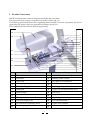
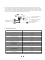
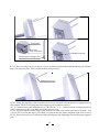
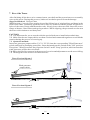
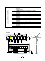
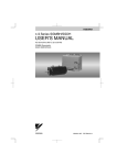
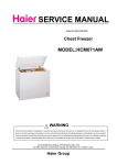
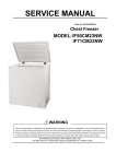
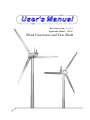
User's Manual
Revised version: Ver 5.3
Applicable Model: 50KW
Wind Generator and Yaw Shaft
CONTENT
1. Product Structure
2. Description of System Function
2.1. Dogvane
2.2. Annemometer
2.3. Wind Generator Direction-Regulating
2.4. Manual Tracking Function
2.5. Time Needed for Direction-Regulating
2.6. Hydraulic Brake
2.7. Wind Generator Schematic Circuit
2.8. Wire Connection Diagram of Yaw Shaft and Generator
( 1)
3.
4.
5.
6.
(5)
Cable for Transmission and Control Communication
Technical Parameter
Power Curve of 50KW Wind Generator
50KW Wind Generator Assembly
6.1. Blades Assembly
6.2. Take Out Yaw Shaft
6.3. Connection of Generator Body and Yaw shaft
6.4. Connection of Two Towers
6.5. Connection of Generator and Tower
6.6. Wire Connection of Generator and Yaw Shaft
6.7. Assembly of Lightning Rod and Dogvane
6.8. Assembly of the Bottom Yaw Shaft Protection Cover
(2)
(6)
(7)
(7)
7. Erect the Tower
8. Assembly Precautions
9. Daily Maintenance
10. Safety Precautions
11. Troubleshooting
(16)
12. 50KW Yaw Shaft Power Box
12.1. Structure Diagram
12.2. Instruction of Connected Switch, Terminal Blocks and Wire Connection
12.3. Wire Connection Diagram of Power Box and the Whole System
13. Annex: Anemometer Assembly
(21)
(18)
(19)
(20)
(20)
(23)
1. Product Structure
50KW wind generator consists of generator body and yaw shaft .
The generator body consists of generator, blades, brake pad, etc..
Yaw shaft system has the direction-regulating function and it consists of gearbox, directionregulating DC motor, dogvane, hydraulic braking system, etc..
The Components listed as the following drawing.
18
1
19
2
3
4
5
6
7
8
20
9
21
10
11
12
13
14
15
16
22
23
24
17
Name
NO.
Name
NO.
1
Blades
13
Hydraulic brake assembly
2
Generator
14
Braking stroke switch
3
Nose cone
15
DC motor wire connector
4
Lifting lug of the generator
16
DC24V hydraulic braking motor
5
Blade pressing plate
17
Braking grade probe
6
Brake pad
18
Upper yaw shaft protection cover
7
Brake caliper
19
8
Gear box
20
Seal cover
Dogvane
9
Wind generator output cable terminals
21
Lightning rod
10
Yaw shaft angle probe
22
Yaw shaft baseplate
11
DC Direction-regulating motor
23
Signal wire terminal
12
Pressure gauge
24
Bottom yaw shaft protection cover
1
2. Description of System Function
50KW wind generator is directly driven by rotor blades without any other speedup equipment .
The patented generator with high efficiency settles in front of the rotor blades, which is helpful
to radiate heat.
50KW wind generator system consists of the following 9 parts:
generator body (including rotor blades), yaw shaft, yaw shaft power box, tower, wind generator
PLC controller, rectifier/dumping controller, inverter, dump load, energy storage components
(battery bank or state grid).
2.1. Dogvane : It receives wind signal, indicates wind direction, and reads the average value
of the angle measured by dogvane every 120s. If the angle read by dogvane is larger than 10°,
wind generator controller will drive DC direction-regulating motor with yaw shaft to deviate
to fulfill the function of facing wind automatically.
2.2. Anemometer : It measures wind speed. If the measured wind speed is over the start-up
wind speed wind generator requires continuously within 30s, the auto wind direction tracking
system will start up and the controller will drive DC regulating-direction motor to seek wind
direction automatically. When the blades are facing wind direction, they can receive the maximum wind energy, and when the blades are parallel to wind direction, they can not receive any
wind energy and stop running.
CAUTION:
The factory-set start-up wind speed value of wind generator is 1m/s. If wind speed is less than
the required start-up wind speed value, the system will keep in standby mode.
Users can change the start-up wind speed of wind generator in the "User Parameter Setting"
window according to actual needs.
2.3. Wind Generator Direction-Regulating
When blades rotate too fast owing to high wind speed, the controller will alarm for "over
rotation speed". And the controller will drive DC direction-regulating motor with yaw shaft
to deflect about 30° off wind direction at this time.
If the blades still rotate too fast, the controller will further drive blades to deflect 60° off wind
direction and then the blades will be parallel to wind direction and stop running. In 5 minutes,
the controller will drive DC direction-regulating motor to seek wind direction again.
If the alarm signal isn't released, the blades will keep parallel to wind direction.The controller
will drive DC direction-regulating motor to make the blades deviate 90° and parallel to wind
direction if any of below situations occurs.
2.3.1. When the wind generator's temperature is up to 145℃ , the controller indicates "over
temp"
2.3.2. When wind speed is over the "system alarm wind speed", the controller indicates "over
wind speed"
CAUTION:
All above functions are based on the "Auto" mode.
2.4. Manual Tracking Function
Select "Manual" window on the screen of the controller, click "Mode switch", and then the
track mode will be switched from "Auto mode" into "Manual mode". Under "Manual" mode,
2
when users press the anticlockwise-rotation or corotation buttons, yaw shaft will stop at any
angle of -270°~ +270° to realize the function of Manual Tracking.
CAUTION:
When wind speed is over than 18m/s, in order to protect the wind generator system from any
unpredictable damage, users can use "manual track" to set the blades aside or back to wind
direction which can make wind generator stop working or set the blades 30°~ 45° off wind
direction. In this way, wind energy received by the blades will decrease and rotation speed
will slow down.
2.5. Time Needed for Direction-Regulating
2.5.1. It takes about 13 seconds for yaw shaft with the blades to deflect 30° off wind direction.
2.5.2. It takes about 38 seconds for yaw shaft with the blades to deflect 90° off wind direction.
2.5.3. It takes about 150 seconds for yaw shaft with the blades to rotate a circle (360°).
2.6. Hydraulic Brake
Under heavy wind, the blades rotate too fast. Users can also switch into manual mode of wind
generator controller and start up the function of "Hydraulic brake" to make hydraulic brake
calipers lock the blades which will stop the blades from rotating.
Or under manual mode, click "Manual stop", wind generator will deflect 90° and stop operation,
then hydraulic braking will meanwhile start up and the brake calipers lock blades.
2.7 Wind Generator Schematic Circuit
Temperature sensor
of wind generator
AC220V(or DC260~DC320V)
(+) L
Anemometer sensor
(-) N
Temperature transmitter
Generator rotation speed sensor
Yaw shaft deflection
angle sensor
Rectifier
Stroke grade transducer
DC 24V
power supply I
Dogvane sensor
Pressure sensor
SIEMENS PLC
Wind
generator
DC 24V hydraulic
brake motor
Relay
Load
Directionregulating motor
3
DC 24V
power supply II
Relay
Inverter
Fuse
Fuse
2.8. Wire Connection Diagram of Yaw Shaft and Generator
Nose cone
Generator body
Wind generator
output cables
Wire
connector B
U2
U2
V2
Wind generator
temperature wires
Temperature transducer
V2
U1
V1
U1
V1
Wire
connector A
To V-
Brake
motor
21
PE
2
V+
Lightning
rod
5
1
V+
V-
V-
NC
7
6
4
19
20
G.
W.
G.
Direct Temp. Direct Speed Grade Pressure
W.
V+ Direct
V-
4
Signal wire
terminal block
Dogvane
Wind generator rotation speed wires
to power box
101 102 Y101 Y102
Brake assembly
Pressure transducer
Directionregulating
motor
Wind generator signal wires (total 13 wires, 1-7,17-21,PE)
Gearbox
After the mechanical connection of wind generator and yaw shaft, the generator body is required
to connect the transmission and communication cables on the yaw shaft and then wind generator
will operate normally.
During this process, the following cables are required to be connected:
four wires of wind generator output cables (U1/V1,U2/V2) ; three wind generator rotation cables;
three wind generator temperature cables and three dogvane cables.
Please connect as the following steps and the wire connection diagram.
2.8.1. Connect 3 wind generator temperature wires (Temp1/Temp2/Temp3) into the temperature
transducer according to the signs. Temp1 connects to the upper terminal, Temp2 connects to the
middle terminal, and Temp3 connects to the bottom terminal.
2.8.2. Connect 4 wires (U1/V1,U2/V2) of the two main output cables separately to terminal A/ B
and tighten them.
2.8.3. Connect 3 wind generator rotation speed wires (G. Speed /V+/V-) to the Signal Wire
Terminal Block
2.8.4. Put on the upper yaw shaft protection cover, assemble the dogvane onto the support pole,
and then connect 3 dogvane wires (W. Direct /V+/V-) separately to the Signal Wire Terminal
Block under the yaw shaft baseplate.
Cables
Wind generator
output cables
Wind generator
temperature wires
Wind generator
rotation speed wires
Dogvane wires
Connect to
Terminal Mark
U1
V1
U2
V2
Temp1
Temp2
Temp3
Wire connector A
Wire connector B
Temperature
transducer
G.Speed
VV+
W.Direct
+
-
1
2
3
Signal wire
terminal block
Dogvane wire
terminal block
VV+
U1
V1
U2
V2
Upper
Middle
Bottom
G.Speed
VV+
W.Direct
VV+
3. Cable for Transmission and Control Communication
There are four main cables for 50KWwind generator extending outward from the below part of
yaw shaft, as shown in the following picture.
Two are wind generator output cables with the specification of 2*25mm 2 for each one.
One is power supply cable for DC direction-regulating motor and hydraulic braking motor with
the specification of 4*1mm 2.
5
2
The last one is signal cable for yaw shaft and power box with the specification of 12*0.3mm .
9 wires of them are for generator rotation speed signal, generator temperature signal, yaw shaft
rotation angle signal, dogvane signal, hydraulic braking signal, the positive and negative power
wires. In addition, connect the external shield metal netting of signal wires together as a ground
cable to prevent from being disturbed during signal transmission.
L+(DC220V) Power wire of direction
-regulating motor
M
V+(DC 24V) Power wire of hydraulic
braking motor
V-
U1
Wind generator V1
output cables U2
V2
Signal transmission
wires
12*0.3mm2+PE
4. Technical Parameters
Rated power(W)
50000
Maximum output power(W)
75000
Charging voltage (V)
DC 360V
Blade quantity (PCS)
3
Rotor blade material
GRP
Rotor blade diameter (m)
Start-up wind speed (m/s)
Φ12
Rated wind speed (m/s)
11
Rated rotating rate (r/min)
150
Wind energy utilizing ratio (Cp)
0.42
Generator output
(double) Single-phase frequency conversion AC
Rated charging current (A)
139
The maximum charging current (in a short time) (A)
208
Output AC frequency (Hz)
0~400
Generator efficiency
>0.92
Wireless tower specification (mm)
Φ1350× Φ530×18000(2segments)
Tower height(m)
18m
Generator weight (kg)
1200
2.0
6
5. Power Curve of 50KW Wind Generator
6. 50KW Wind Generator Assembly
6.1. Blades Assembly
6.1.1. Grip the blades pressing plate with a crane, take out the generator, and then put it on the
floor or the sponge cushion.
Lifting lug of the generator
Blades pressing plate
Generator body
6.1.2. Take off all nuts and bolts of the blades pressing plate, lift up the blades pressing plate
and put one blade root into it. Then tighten the blade with bolts as the below picture shows.
As blades need accurate position, bolts must be fastened tightly against blades. Please use a
hammer to hit bolts into the corresponding holes on the blades.
7
6.1.3. Assemble the second and the third blades in proper order. If the lifting lug hinders the
assembly, please move it to another direction and continue to assemble blades.
CAUTION:
The side marked with "FRONT" shall be adown and windward. Every 3 rotor blades of each
wind generator have passed balance test; they need to be used together. Please do not disorderly
use the blades belonging to other wind generators.
6.2. Take Out Yaw Shaft
6.2.1. Open the packing wooden box
6.2.2. Fetch out the power cables around yaw shaft
6.2.3. Loosen 10*M12 cross screws from the bottom yaw shaft protection cover and take down
the bottom cover.
6.2.4. Loosen 13*M12 cross screws from the yaw shaft soleplate, uplift the upper yaw shaft
protection cover and take it down from yaw shaft.
6.2.5. Put steel wires through the lifting hole under the yaw shaft soleplate and lift yaw shaft.
6.2.6. Connect yaw shaft to the generator head with blades. The detailed steps refer to the
following sections.
the packing wooden box
Upper yaw shaft protection cover
Yaw shaft soleplate
the bottom yaw shaft protection cover
M12 cross screw
Power cable
6.3. Connection of Generator Body and Yaw shaft
6.3.1. Uplift Yaw Shaft
Put steel wires through the lifting hole under the yaw shaft soleplate. Uplift yaw shaft with the
crane hook and slowly descend it to the best position for fixing to the generator
8
Threading
mouth
the lifting hole
the yaw shaft
connection base
CAUTION:
Pull four cables of the generator (including two output cables, one generator temperature cable
and one generator rotation cable) through yaw shaft and connect them to the flange, then pull
them out from the threading mouth at both sides.
6.3.2. Put the brake calipers at the position between brake pad and the generator connection
base, and fasten it with inside hexagon bolts from the direction the generator connects the
flange.
6.3.3. Fasten the brake calipers at the other side with inside hexagon bolts in the same way.
Inside hexagon bolts
the brake caliper
with pipeline
the brake pad
Generator
connection base
9
CAUTION:
1. When out of factory, the brake calipers, the pipeline and hydraulic braking assembly have
been well connected. When do the above connection, users only need to directly fix the brake
calipers onto the generator and then connect it to the flange. Separation between the pipeline
and the brake calipers is forbidden. If the pipeline is removed from the brake calipers, the air
will get into the hydraulic system and prevent the system from normal operation.
2. The final settlement of the brake calipers is finished when the generator is connected to
yaw shaft. Therefore, it will be ok to directly fix the brake calipers onto the generator and then
connect to the flange. Please note that inside hexagonal bolts don't need to be locked tightly
to easily go through the following steps.
6.3.4. Installation of Generator and Yaw Shaft
Align screw holes in the generator connection base with those in the yaw shaft soleplate, and
then fix the generator to yaw shaft with outside hexagonal bolts, flat washers and spring washers.
CAUTION:
There are 3 outside hexagonal bolts on the generator connection base and all bolts need to be
fastened tightly after connection. Thread other outside hexagonal bolts through the yaw shaft
connection base and fix them onto the generator connection base and the brake calipers.
10
6.4. Connection of Two Towers
6.4.1. With the help of a crane and canvas belt, put two towers on the ground in line and try to
align screw holes.
6.4.2. Connect two towers with outside hexagonal bolts, flat washers and spring washers and
fasten nuts.
6.4.3. Prop up the top of the tower with a 1.6m-height support and then wipe out the crane.
See the below picture.
Canvas belt
1.6m
6.5. Connection of Generator and Tower
6.5.1. Place the bottom yaw shaft protection cover from the top of tower and then do the
following steps.
6.5.2. Pull steel wires through the lifting hole under the yaw shaft soleplate and uplift yaw
shaft well connected with generator.
6.5.3. Pull the cables under yaw shaft with iron wires from the top of tower to the thread holes.
6.5.4. Uplift yaw shaft and move it near to the flange at the top of tower. Align one bolt hole
and fix it with outside hexagonal bolts, flat washers and spring washers.
6.5.5. Align other screw holes separately with outside hexagonal bolts, flat washers and spring
washers.
6.5.6. Fasten nuts and yaw shaft will be fixed onto the tower.
11
6.5.7. After settlement, please remove the wires, then assemble and fix nose cone with M16*
12 stainless steel bolts.
Stainless
steel bolts
Nose cone
6.6. Wire Connection of Generator and Yaw Shaft
6.6.1. Connect four main wires of generator output cables (U1/V1, U2/V2) to wire connectors
A and B at the both sides of gear box and fasten them tightly.
Signal wire terminal block
Temperature
transducer
Wire connector B
Wire connector A
12
6.6.2. Connect and fasten generator temperature signal wires to the temperature transducer
which is at the side of gearbox.
+
Temp1
Temp2
-
Generator
temperature
signal wires
Temp3
Temperature transducer
NOTE:
There are three thin wires in the generator temperature signal cable, connect the one marked
"Temp 1" to the top terminal block on the temperature transducer, the one marked "Temp 2"
to the middle terminal block, and the one marked "Temp 3" to the below terminal block.
6.6.3. Connect and fasten three thin wires (G. Speed / V-/V+) in the generator rotation cable
to the signal wire connector respectively.
Please connect as shown in the diagram in Section 2.7.
6.7. Assembly of Lightning Rod and Dogvane
6.7.1. Set the upper yaw shaft protection cover on the yaw shaft soleplate and don't fix it.
6.7.2. Insert lightning rod and the end of dogvane support pole from the corresponding holes
of the upper yaw shaft protection cover into the corresponding taper hole of yaw shaft soleplate.
6.7.3. The hinge slot at the end of dogvane support pole is corresponding to the position of fixed
screw on the taper hole of soleplate. Tighten the screw and press it into the hinge slot to fix the
dogvane pole.
6.7.4. Tighten lightning rod and the end of dogvane support pole with M30*1.5 round locknuts.
13
Fixed bolt
Dogvane
wire connector
Round locknut
the position of hinge slot
6.7.5. Put seal rings into seal press covers and thread them through lightning rod and the
dogvane support pole. Don't tighten them temporarily.
Seal press cover
6.7.6. Strap the dogvane cable with thin iron wires, and pull it from the top of support pole to
the bottom. Then fix the dogvane onto support pole with zero screws.
6.7.7. Connect three thin dogvane wires (W. Direct / V-/V+) at the bottom of support pole to
wire connectors on the yaw shaft soleplate respectively.
6.7.8. Align bolt holes on the upper yaw shaft cover with ones on the yaw shaft soleplate. Use
a screw driver to fix the upper yaw shaft cover onto the yaw shaft soleplate with cross screws.
6.7.9. Screw the seal cover enclosed with seal ring onto the lightning rod and dogvane support
pole.
14
Zero screw
6.8. Assembly of the Bottom Yaw Shaft Protection Cover
6.8.1. Move slightly the bottom yaw shaft cover set around the tower to get close to the upper
cover.
6.8.2. Align bolt holes on the bottom cover with ones on the yaw shaft soleplate. Use a screw
driver to fix the bottom cover onto the yaw shaft soleplate with cross screws.
CAUTION:
The upper and bottom protection covers are made up of glass fiber reinforced plastic. When
installation, the embedded nuts for internally mounted assembly can't bear the tightening
force of the spanner. Only the screw driver is used to tighten screws.
15
7. Erect the Tower
After finishing all the above wire connection on yaw shaft and the protection cover assembly,
erect up the tower. During this process, blades are needed to protect from the damage.
Suggested Method: Using a Crane
When hoisting, iron wires are used to thread the lifting lug of wind turbine and hang in the
hook of the crane. Gradually uplift the tower until it is vertical with the ground. Align screw
holes of the tower flange and the anchor rods. Slowly lower the tower and fasten the tower
flange with nuts, flat washers and spring washers. While aligning, the personnel need to turn
the tower with caution to avoid any hurt.
CAUTION:
7.1. It is important for you to consult with the specialized tower installation technicians.
7.2. Make sure the two output cables are short circuited and connected together to avoid blades
rotation during the process of erecting up.
7.3. Operation method:
Insert two generator output cables (U1/V1, U2/V2) into the corresponding "Wind Generator"
switch on Rectifier/Dumping controller, fasten them and put this switch at the "ON" position.
Then place "Wind Generator Stop/Operate Switch" at the "Stop" position, which means that
wind generator will be short circuited.
7.4. Safety shall be first concern in the process of erection and adjustment to avoid tower falling.
7.5. The diagram of the whole erection as belows:
Tower Erection Digram 1
Wind generator
output cables
Tower Erection Digram 2
16
Tower Erection Digram 3
Tower Erection Digram 4
Nuts/
Spring washer/
Flat washer
17
8. Assembly precautions
8.1. When a product is to be assembled, please open the cover of the gear box lubrication hole
and input about 8L matching engine oil with the acutilingual bottle. (Oil level should get to the
indicating level.)
20 ML
100
Cover for lubrication
hole of gear box
460# oil for the gear
X8
1L
100
Observation lens
for oil level
Acutilingual
bottle
20ML
CAUTION:
The 460# oil is special for gear box, and it can not be used as speed-reducer oil of directionregulating motor.
8.2. Each set of rotor blades is made up with 3 blades which have passed the rigorous balance
test and can not be exchanged between two different wind generators, otherwise blades will run
abnormally which will result in serious shaking. Therefore, please be careful to avoid mixing
the blades when open the packing box.
8.3. The power generated by off-grid wind turbine will charge batteries after rectified. Different
wind turbines collocate with different numbers of batteries. Please strictly follow the owner's
manual to choose the right number. If the battery voltage is too high or too low, the generator
system may work improperly or some parts of the system could burn out.
8.4. 50KW off grid wind turbine collocates 30 pieces 12V-400/600AH batteries.
CAUTION:
New batteries need to be charged fully by the state grid. Each set of battery bank rank in series.
Strictly connect the battery's anode/cathode to the battery terminal (+/-) of rectifier/dumping
controller.
18
8.5. Emergency shut-down
8.5.1. Please use the "Manual mode" function to switch the control model into "Manual track"
and press the "Manual stop" button to drive yaw shaft to deflect 90° to let blades parallel to
wind direction before typhoon or gale (such as more than grade 10) coming.
Meanwhile, hydraulic braking system will start up and the brake calipers will lock blades.
8.5.2. Then put "Wind Generator Stop/Operation Switch" at the "Stop" position and wind
generator will stop work.
8.5.3. After heavy wind, please put "Wind Generator Stop/Operation Switch" back to the
"Operation" position and switch "Manual mode" into "Auto mode", wind generator will work
normally.
Stop
Operation
ON
ON
CAUTION:
"Wind generator stop/operation switch" can only be switched from "Operation" to "Stop"
when blades stop rotating or rotate at a very low speed.
Do not slide switch when blades rotate at a high speed, or it will cause a big shock to wind
generator or burn the generator.
9. Daily Maintenance
50KW wind generator is highly reliable and it does not need frequent maintenance. However,
the overall system of wind turbine must be inspected and maintained regularly to ensure the
system's normal operation.
9.1. Screw Inspection
Check and fasten screws on the blades flange, yaw shaft and tower regularly. This work should
be done at least one time every year.
9.2. Oil Exchange
The lubrication in the gear box has to be renewed every two years.
9.3. Transmission Line Inspection
Check whether the connecting points of the cables are well-connected or corroded.
9.4. Battery Maintenance
Regularly check and maintain battery bank as per the maintenance requirements of batteries.
If there is no wind for a long time, batteries should be fully charged by the state grid to avoid
the loss of capacity.
19
10. Safety Precautions
50KW wind turbine is designed under strict safety regulations. However, any electrical or
mechanical equipment during installation or operation can cause potential inherent dangers
if proper safety precautions are not taken.
Please read the following safety precautions thoroughly before you choose the installation
location, plan to install or operate wind turbine.
10.1. Mechanical hazards
Blades rotation is the most serious mechanical hazards. Please don't install wind turbine where
anyone can get in touch with the blades.
10.2. Electrical hazards
50KW wind turbine is equipped with needed protection device so that it will be short circuited
under over-voltage or over-current. Don't forget that the potential dangers still exist. So please
be careful during the process of connecting wires and other electronic equipments. Undersized
wire or a bad connection can cause over-current electrical dangers and overheating in wiring
systems that could cause fire or other personal dangers. Thus it is important to check wire
connection in daily maintainence.
CAUTION:
Don't stand near wind turbine during gale weather. It is recommended that users must press
the "Manual stop" button to make hydraulic calipers lock the blades in the case of extremely
rough weather (such as typhoon or hurricanes) to avoid unpredictable accidents.
11. Troubleshooting
Problems
Possible cause
Solution
Blades can’t rotate steadily,
Unbalance of the blades
shaking abnormally
Check whether mistake
the blades which are not
belonging to one set.
Enough wind,but blades
do not rotate or rotate
slowly
1. The two output cables
are short circuited.
2. Generator is burnt out.
1. Check whether the two
output cable are short
circuited.
2. Change the generator.
Generator loses load
Check whether the output
cables are open circuited,
or fuses are melted down.
Then reconnect the load.
Blades rotate faster
than normal
20
12. 50KW Yaw Shaft Power Box
12.1. Structure Diagram
50KW yaw shaft power box is to receive the order of wind generator controller and supply power
to two DC motors on the yaw shaft. The case is made of stainless steel waterproof materials.
The components are listed in the below diagram.
2
1
Door lock
2
24V power supply
3
Rectifier bridge
4
Relay
5
Connected switch
5
6
Connecting terminal
6
7
Connection lid
3
4
1
7
V+ V- 1 2 3 4 5 6 7 17 18 19 20 21 V+ V- V+ V-
PE
L+ M
PE
12.2. Instruction of connected switch, terminal blocks and wire connection
N
L
AC Input
Cables
Output cables
DC motor
power line
Terminal
mark
Cable
Mark
L
L
Connect to PLC controller power output L
N
N
Connect to PLC controller power output N
L+
101
Connect to anode of DC direction-regulating motor
M
102
Connect to cathode of DC direction-regulating motor
V+
Y101
Connect to anode of hydraulic braking motor
VPE
Y102
Connect to cathode of hydraulic braking motor
PE
Protective grounding
Aplication
21
Yaw shaft power box and wind generator
2
signal transmission
lines 12*0.3mm
PE
PE
Connect to outer screen metal net of signal cables
1
V-
2
Q0.0
DC24VAnticlockwise rotation signal of yaw shaft
3
Q0.1
Clockwise rotation signal of yaw shaft
4
4
Generator rotation signal
5
5
Yaw shaft angle signal
6
6
Wind direction signal
7
7
Generator temperature signal
17
Q0.2
Hydraulic brake start-up signal
18
Q0.3
Hydraulic brake release signal
19
19
Hydraulic brake grade signal
20
20
Hydraulic brake press signal
21
21
Released signal
V-
1
DC24V-
V+
2
DC24V+
12.3. Wire connection Diagram of power box and the whole system
NC
NC
3
17 18
L+ M
19 20 21 2 1
V+ V- 1 2 3 4 5 6 7 17 18 19 20 21 V+ V- V+ V-
Wind
generator
DC motor
power line 4*1mm2
N
Wind generator controller
OFF
L
OFF
1 2 3 4 5 6 7 8 9 10 11 12 13 14 15 16 17 18 19 20 21
PE
L
OFF
L
N
PE
OFF
PE
4 5 6 7
Signal transmission line 12*0.3mm2
(power supply box--yaw shaft)
PE
Yaw shaft
power box
N
Signal transmission line 12*0.3mm2
(controller--power supply box)
22
GND bar
13. Annex: Anemometer Assembly
13.1. Please refer to the steps of dogvane assembly. Pull the anemometer cable through the
support firstly and then fasten anemometer to the support with a screw.
13.2. Settle the anemometer support to a place near to wind generator to make sure the
anemometer can detect wind speed normally. It is also ok to assemble the anemometer onto a
stand. Make sure that the anemometer should be in similar height with wind generator. This
will ensure the wind speed data collected by the anemometer is correct.
Zero-locking screw
Anemometer
Wind generator
controller
Support
Anemometer wire
8 9
Stand (matched by user)
NOTE:
Anemometer connecting wire is 30m.
23
10