1
CERN, European Laboratory for Particle Physics
SL Division, Experimental Areas Group
CH-1211 Geneva 23, Switzerland
H8
SPS Beam Line
User Guide
Issue:
Revision:
Reference:
Created:
Last modified:
Prepared By:
Draft
0
ATLAS TDR-xx
10 October 1996
10 October 1996
ATLAS/XYZ Collaboration
H8
SPS Beam Line
User Guide
23 May 2002
All trademarks, copyright names and products referred to in this document are acknowledged as such.
ii
H8
SPS Beam Line
User Guide
23 May 2002
Table Of Contents
1
The Layout of the H8 Beam . . . . .
1.1 Different modes of H8 operation . .
1.2 Beams available in H8 . . . . .
1.3 Experimental areas in H8 . . . .
. .
. .
. .
. .
. . .
. . .
. . .
. . .
. . .
. . .
. . .
. . .
. . .
. . .
. . .
. . .
. .
. .
. .
. .
1
1
2
2
2
The Control Tree .
.
.
.
.
.
.
.
.
.
.
.
.
.
.
.
.
.
.
.
.
.
2
3
Beam Files
.
.
.
.
.
.
.
.
.
.
.
.
.
.
.
.
.
.
.
.
.
3
4
Fine Steering and Focussing of the Beam
.
.
.
.
.
.
.
.
.
.
.
.
.
4
5
Beam Intensity and Momentum Spread .
.
.
.
.
.
.
.
.
.
.
.
.
.
4
6
The type of particles in your beam .
.
.
.
.
.
.
.
.
.
.
.
.
.
5
7
Access to your zone . . . . . . . .
7.1 SPECIAL features in zone 168 . . .
. .
. .
. . .
. . .
. . .
. . .
. . .
. . .
. .
. .
6
8
8
Using the detectors / beam-tuning .
.
.
.
.
.
.
.
.
.
.
.
.
.
.
.
8
9
Further problems .
.
.
.
.
.
.
.
.
.
.
.
.
.
.
. 10
10
Special Beams . . . . . . . . . . .
10.1 H8 operation as 450 GeV "microbeam" .
10.1.1 Interlock conditions . . . .
10.2 TAX5 - two options for the microbeam.
10.3 Tuning the microbeam . . . . . .
. .
. .
. .
. .
. .
.
.
.
.
.
. .
. .
. .
. .
. .
.
.
.
.
.
. .
. .
. .
. .
. .
.
.
.
.
.
. .
. .
. .
. .
. .
A
Modification History. . . . . . . . . . . . . . . . . . . . . 13
A.1 H8 Beam updates during 2000 . . . . . . . . . . . . . . . 13
A.2 REVIEW of your past runs . . . . . . . . . . . . . . . . . 13
B
Experimental Scalers .
C
Beam Elements . . . . . . . . . . . . . . . . . . . . . . . 17
C.1 Trigger Counters . . . . . . . . . . . . . . . . . . . . 17
C.2 Steering Magnets . . . . . . . . . . . . . . . . . . . . 17
D
Beam Focusing onto ATLAS Test Setups.
.
.
.
.
.
.
.
.
.
.
.
.
. 19
E
Operation for “very low” Beam Energies.
E.1 The “low energy wiggle” . . . .
.
.
.
.
.
.
.
.
.
.
.
.
.
.
.
.
.
.
.
.
.
.
.
.
. 21
. 21
.
.
.
.
.
.
.
.
.
.
.
.
.
.
.
.
.
.
.
.
.
.
.
.
.
.
.
.
.
Table Of Contents
.
.
.
.
.
.
10
10
10
11
11
. 15
iii
H8
SPS Beam Line
iv
Table Of Contents
User Guide
23 May 2002
H8
SPS Beam Line
User Guide
23 May 2002
List of Tables
Table 0-1
p. 15
Table C-1
p. 17
Table C-2
p. 17
Table D-1
p. 19
Table E-1
p. 21
The configuration of the NODAL experimental scalers for the H8 beam line.
List of Tables
v
H8
SPS Beam Line
User Guide
23 May 2002
List of Figures
Fig. E-1
p. 22
The Low Energy Wiggle.
vi
List of Figures
H8
SPS Beam Line
User Guide
23 May 2002
1 The Layout of the H8 Beam
The H8 beam is a secondary particle beam that provides hadrons, electrons or muons of energies between 10 and 400 GeV/c, as well as 450 GeV/c (primary) protons and up to 400 GeV/c
per charge (32.8 TeV) primary Pb ions. The H8 beam is a part of the SPS North Area (EHN1,
building 887). This note gives a short introduction to the basic elements of the H8 beam. For
more detailed information the users are referred to one of the SL-EA liaison physicists.
A 450 GeV/c primary proton beam is extracted from the SPS towards the North Areas, split
into three beams of which one is directed onto the T4 primary target. Typical intensities of this
primary beam are a few 1012 protons per burst. For proper operation of the beams the symmetry on
the T4 target should be at least 65%, with a small "a" indicating that the angular asymmetry is included
in the value displayed. This number as well as the T4 intensity can be read from the so-called
’PAGE-1’ TV screens in the electronics huts and control rooms. From the T4 target, three secondary beams are derived: the P0 beam to ECN3, the H8 and the H6 beams. The momenta and polarities of the three beams are strongly correlated. For example, if the P0 beam runs at 450 GeV/
c (the standard condition), the H8 beam can run at any negative polarity (-10 to -400 GeV/c) or
at positive polarities up to 180 GeV. The H6 beam always runs at the polarity of the H8 beam
and typically up to 50% of the momentum chosen in H8. Any of these "front-end" changes of the
beams should be done by an SL-EA liaison physicist or a CRN operator and only during working hours.
1.1 Different modes of H8 operation
There are five distinct modes of operating the H8 beam:
1. as a 450 GeV proton micro-beam (see appendix 1)
2. in the high resolution mode
3. in the high transmission mode
4. in the "filter" mode (testbeam mode, also used to produce tertiary beams)
5. as a heavy ion beam (not discussed in this note)
For a user asking for different particles/energies, the "filter" mode is the optics used to calculate
the beam files - it provides a large range in energies from 10 to 300 GeV/c and several possibilities to create tertiary beams (see below).
For a (low intensity!) 400 GeV/c hadron beam, the high resolution mode has to be used because
of lack of magnet strength in some relevant quadrupoles (Q7). Note that at positive polarity, the
400 GeV/c beam consists mainly of protons, whereas at negative polarity, it contains mainly
pions. Information on beam composition in secondary beams can be found in the following
reports: (1) H.A. Atherton et al., CERN Yellow Report No. 80-07, (2) G. Ambrosini et al., CERNEP-99-019, Europhys. Journal C).
1
H8
SPS Beam Line
User Guide
23 May 2002
1.2 Beams available in H8
If the P0 beam is off, the H8 beam can run in the 450 GeV/c "micro-beam" mode (see below).
This mode implies significant hardware changes to the beamline and switching to and from the
micro-beam requires time and a stop of the whole North Area for several hours.
If the H8 beam runs as a secondary hadron or electron beam in the "filter" mode, a further "TARGET" can be introduced into the beam to produce tertiary beams of lower energy. Typically, this
is done when H8 runs at e.g. -200 GeV/c, and tertiary beams then range from -10 to -150 GeV/c
(for pions, 10 and 20 GeV/c tertiary beams are marginal). This mode of operation allows an
easy change of beam momentum, which can be done by the H8 users from their beam control
terminal simply by loading a different file.
1.3 Experimental areas in H8
Like all other beams in EHN1, we distinguish experimental areas (at present only NA45 in H8)
and test zones. Since 1997, the zone H8A is used by ATLAS inner detectors and TileCal (hadronic calorimeter), H8B by ATLAS EMB (liquid argon electromagnetic barrel calorimeter) and ATLAS muon detectors. There are two beam control terminals for ATLAS: the H8A terminal in the
common ATLAS control room on the ground floor, and the H8B terminal in the control room of
the barrel em. calorimeter upstairs (HNA468). From the point of view of emergency stops, intercom, beam index etc., the two zones H8A+B are treated as a single one. From time to time, some
test beam activities with bent crystals take place in an area near door 128 (not a formal test
zone).
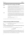
2 The Control Tree
The user wants to select the energy and polarity of the particles in his beam, to steer the particles into a selected part of the detector and to adjust the spot size (focussing). He needs to
choose the type of beam particles, control the beam intensity and eventually to stop the beam
and get access to his experimental zone. He will use the beam instrumentation to check certain
properties of the beam. Finally he needs to monitor that all the equipment in the beam is functioning correctly.
All these tasks can be performed from the beam terminal (an X-terminal), connected to a cluster
of HP UNIX computers running the NODAL system. From this terminal the user controls the
beam and related equipment through the so-called TREE program, invoked by the command
’RUN TREE’, or if necessary ’RUN <index> TREE’ , where the ’index’ is 217 for NA45 and 205 for
the ATLAS test zones. From then onward the user just follows the menus offered by the control
tree.
Note that the NODAL system traditionally only accepted upper case! In case you get lost or
stuck, you can leave the control tree by typing CTRL_C. You can then enter the tree again by
’RUN TREE’. In case of mis-typing, you should use ’backspace’. In emergency cases only, switch
terminal OFF/ON.
2
H8
SPS Beam Line
User Guide
23 May 2002
Additional windows can be obtained to work (or count) in parallel by selecting (in the dark area
of your screen) local X-terminal with the mouse. The window will open in unix mode with the
’prompt’ eanorth: - you have to type NODAL to continue.
3 Beam Files
Normally each user has a number of different beam energies and corresponding beam intensities at which he wants to run his experiment. These sets of conditions are described by Beam
Files. In each index (205 or 217) there are 10 read-only beam files, and up to 99 beam files, for
use by the experiments. The EA files are called H8.A to H8.J and the user files are numbered
H8.1 to H8.99. These files contain all magnet and collimator settings. A list of available files is
obtained by:
FILES / LIST
Usually beam files are prepared by or after discussion with the responsible EA liaison physicist,
although experienced users will sometimes change files themselves.
The actual conditions in use at any given time are described by another beam file, called "the
BIM.0 file".
The user can select new conditions by loading a file from the tree:
FILES / LOAD / H8.nn
and then answering the questions. In particular one has the option to change only magnets,
only collimators or both. Magnet current changes are fast, collimator changes may be much
slower. This command copies the values of file H8.nn into BIM.0 and sets the proper magnet
currents and/or collimator positions. NOTE that the target and absorber are NOT changed
when loading a file!
WARNING: Changing from a tertiary beam (typically with wide open collimator settings) to a
secondary beam, one should first load only the collimators, then the magnets. Otherwise, during some bursts very high intensities might be present in your beam-line.
It is wise to check that the equipment has responded correctly to the requested changes by typing
STATUS / CHECK or STATUS / MAGNETS and STATUS / COLL
thus verifying that the currents (positions) read correspond within tolerances to the currents
(positions) in BIM.0. Tolerable deviations are 0.2-0.3 Amps for BENDS and QUADS, 0.5 Amps
for TRIMS, 0.2 mm for collimators. In case of problems, try once more to load the file. If the
problem still persists, call the CRN operator (using the intercom - CRN - or phone 75566, NATEL 160137). The EA liaison physicist can do nothing for you in this case!
In case of doubts about your beam particles or to check other parts of your beam, please check
STATUS / GENERAL
which will give you a full account on your TARGET, ABSORBER, file loaded, collimator and
TRIG status etc. - this will allow you to judge whether you are in a "strange" mode or not. A
more complete picture can be obtained by using
STATUS / MODE
3
H8
SPS Beam Line
User Guide
23 May 2002
4 Fine Steering and Focussing of the Beam
BENDs
Steering of a beam is done by BENDing magnets (dipoles). Normally the currents
in the dipole magnets are defined correctly in the beam files and the user should
not modify them without discussing with the EA physicists.
QUADs
Quadrupoles are like lenses in conventional optics, they are used to (de-)focus the
beam and thus change the spot size of the beam. The spot size of the beam is controlled by the last QUADs in front of each experiment. Which quad controls what
projection depends on the beam file used. In the beam files these quads are usually
defined to minimise the spot size at the main experiment locations.
Note: different users may choose a different beam spot size - the quadrupole values
saved in the files are therefore not always the ones you like - in H8A/H8B, this
concerns mostly the values of Q17 and Q18 (cf. Appendix 3).
TRIMs
Trim magnet are correction dipoles, used for fine steering of the beam. Normally
the last TRIMs upstream of each experiment should only be used for steering. Typical values for TRIM10 (vertical) and TRIM9 (horizontal) steering to ATLAS
Tiles are 23 mm for a 100 A change at 100 GeV/c beam momentum (proportional
to p and inversely proportional to the distance from the TRIM). When starting a
run with a given beam file, a TRIM scan should be made to make sure you have the
correct steering.
The currents in these magnets can be set using e.g.
TUNE / SET/ TRIM / 8 / current
These changes are not saved in the files (except the BIM.0 file for the present status)!
5 Beam Intensity and Momentum Spread
The beam intensity for a secondary beam is normally controlled by three collimators, namely:
C3
Momentum defining collimator (vertical),
C5 and C6
X and Y acceptance collimators
The momentum defining collimator C3 defines the momentum of the particles transported to
your detector. The momentum byte ∆p/p is proportional to the opening of the collimator. A gap
of 3 mm gives a ∆p/p of approximately 0.1%.
More accurately, the general expression to calculate the full width momentum spread is
2
2
( C3 + C9 )
∆p
------- = ---------------------------------%
27
p
5-1
where C3 and C9 are the full width opening of these collimators in mm, 27 mm/% is the vertical momentum dispersion of the beam at C3 compared to C9. This expression holds for a tertiary beam in all cases, while for a secondary beam C9 is often more open than the beam image
and should be replaced by 2 mm (the T4 target thickness, i.e. the "source size" of a high energy
secondary beam), in which case C3 usually dominates the resulting ∆p/p.
4
H8
SPS Beam Line
User Guide
23 May 2002
Decreasing the opening of C5 and C6 results in a (non-linear) reduction of rate. It is not related
to the momentum band of the beam. The collimators are controlled by (e.g.)
TUNE / SET / COLL / 3 / JAWS/ -5 / 5
or
TUNE / SET / COLL / 5 / SLIT / 24
Note that depending on momentum byte requirements it may be more advantageous to close
C3 than C5,6, or conversely, to open C5,6 rather than C3.
Sometimes it turns out not to be possible to reduce the rate sufficiently by closing C5 and C6.
Other collimators have to be closed in those cases, material can be put in the beam, and if necessary the first 3 quadrupoles can be set to zero.
6 The type of particles in your beam
Overview of your present beam:
In order to get rapid information on the beam you are currently using, you may type:
STATUS / MODE
You will get the status of TARGET, ABSORBER, relevant collimators etc..
Several options exist for the type of particles in your beam (ions not treated here):
450 GeV protons
These are selected at 0 degrees from the production target and transported to a set
of micro-collimators (C12 and C13) between the two main vertical BENDs. At
these microcollimators, a new "source" of the beam is defined (intensity reduced
by orders of magnitude). Setting up and most of the operations of the micro-beam
are done by the SL-EA physicist - see the Appendix.
’Pure’ electrons
secondary beams: These are obtained by loading the appropriate file
and by assuring that the dangerous material (target,
absorber and TRIG counters, beam dump, etc.) are
removed from the beam. Separation of electrons from
hadrons is achieved by the synchrotron radiation
energy loss in the big BENDs followed by collimation
of the hadrons. The effect is very strongly energy
dependent. Example: separation of pions and electrons at 200 GeV is 16 mm at collimator C9 in H8.
Note: Limited purity of this beam has been observed,
in particular in positive polarity. The electrons are
however focussed in the centre of the beam, while
pions and muons occupy a larger phase space. It has
been found that the best purity in the experiment is
obtained if the secondary pion beam is used first for
steering onto the experimental counters, then copying
the TRIM values found for the electron case. An
increased purity is expected as of 2000 due to the
addition of C7, which precedes C9 and should always
the same jaw positions as it.
5
H8
SPS Beam Line
User Guide
23 May 2002
tertiary beams:
’Pure’ hadrons
Are obtained by loading the appropriate file and
choosing Pb as a TARGET (see below). Downstream
of this target, all other Pb sheets and TRIGs should be
out of the beam. Momentum selection of the tertiary
beam in second main BEND, separation from hadrons
due to production mechanism in the Pb foil TARGET
(degrading electrons, by bremsstrahlung, much more
the hadrons).
secondary beams: Choose the appropriate beam file and put in the Pb
TARGET to remove electrons. In addition, further
purification can be obtained by entering an
ABSORBER (4, 8 or 18 mm of Pb) into the beam.
tertiary beams:
Choose the appropriate file and use POLY or Cu as a
TARGET. Momentum selection as above, use the
ABSORBER to "kill" the electrons in the tertiary beam.
Note that the Cu target generally gives less intense
but more clean tertiary hadron beams.
Mixed beam
Do you really want it? You get it by not applying the prescriptions above, i.e.
choose a tertiary hadron beam and do not remove electrons by lead sheets.
Muons
Choose a secondary hadron beam file and close collimator C9 and C10 asymmetrically (i.e. setting the jaws to +45 and +46 mm respectively). The muon momentum is selected by BEND5 and BEND6. For higher muon fluxes, open all
collimators upstream of C9.
The TARGET can be changed by:
TUNE / SPECIAL / MODE / TARGET /
and the ABSORBER by:
TUNE / SPECIAL / MODE /ABSORBER /
and the situation of the TRIG counters and MWPCs can be observed or changed by:
TUNE / MEAS / TRIG /
TUNE / MEAS / MWPC / MOVE
Note however that in general a TRIG counter is always mounted on one support with a MWPC,
e.g. TRIG1 with MWPC1+2.
7 Access to your zone
Frequently you will need access to your zone in order to modify, adjust, move or repair your apparatus. This is done through the command:
ACCESS / DOOR / 138 / OPEN for the NA45 zone
ACCESS / DOOR / 158 / OPEN for the H8A test zone
ACCESS / DOOR / 168 / OPEN for the H8B test zone
6
H8
SPS Beam Line
User Guide
23 May 2002
Type in your name when the program asks for it. Wait until you get the message which confirms
that you have access, "ACCESS GRANTED"! Then go to the door (e.g. marked PPE158), make
sure the lights ’ACCESS WITH KEY’ are flashing, push the button with a key on it, take the key
for which the red diode lights up and use it to open the door and enter the zone (PRESS THE
DOOR HANDLE SLOWLY!!!). Every person entering the zone has to take a key and keep it
with him - your safety depends on this action!!! When you come out of the zone you should put
back the key and turn it into its normal position. When the last person has finished, check that
nobody is left in the zone, put back the last key, push the red button marked ’END OF ACCESS’
(do not forget - otherwise you will not get beam and have to walk back to the door later...!) and
go back to your barrack.
At your beam terminal, type e.g.:
ACCESS / DOOR / 158 / BEAM ON,
type in your name (you are responsible for persons left in the zone!) and wait till beam comes
back.
The SL Radiation Safety Officer M. Jonker has issued a memorandum describing the rules for
access. The main change is that:
1. when more than 8 persons need to enter the experimental area, the experimental team
should change the zone to FREE access mode
2. only the CRN operators can change from FREE to KEY access mode. Such a change can
only be made if the zone is being searched following a prescribed search procedure. The
search is made by the CRN operator or by an authorised person of the experiment (whose
name will be noted by the CRN operator).
3. Search authorisaton is granted by the RSO of SL and/or the RSO of PPE to a limited
number of persons from the experiment which are designated by their GLIMOS.
All experimental areas have been equipped with a timer. If a door on key access stays open for
longer than 1 minute, the zone is automatically set on FREE access. FREE access can also be requested from your beam terminal via:
ACCESS / DOOR / 158 / FREE
In both cases, a search of the area is needed to go from FREE access to access WITH KEY (see
above, “new in 1997”).
SEARCH done by 1 CRN operator + 1 Physicist of the experiment!
After an access, it is wise to check that all magnet currents are OK by typing
STATUS / MAGNETS
If the magnets do not switch on properly, then try "ACCESS / BEAM ON" again or try to set
them to their BIM.0 value by TUNE / SET. If the problem persists, call the CRN operators.
Important : In the door itself, next to the handle, there is a round 'pastille' with a dim red light in
it, which should be pushed in emergency cases only ! Whenever this button is pushed, it requires an operator to come over and reset the emergency stop manually. This may cause significant loss of beam time, in particular because the operators are often working on another
problem elsewhere!
7
H8
SPS Beam Line
User Guide
23 May 2002
7.1 SPECIAL features in zone 168
• The motorized beam dump separating 158 from 168 allows access to the 168 (H8B) area at
any time without stopping the beam in zone 158 (H8A). Exception: High Intensity running of H8 - the zone 168 will be fully interlocked and the beam stopped in the tunnel
when access is requested on 168.
• The garage of H8B, for the preparation/modification of the Lar endcap modules and cryostat, can be opened by opening door PPG168 using a normal key taken with the standard access procedure at door PPE168. However, opening this large door (which
potentially allows a lot of people to enter the area in a short time) will create a special
FREE condition in zone 168, requiring a search including a special search box located in
the far corner (Jura side) of the H8B zone.
• The timer of zone PPE168 has been set to 5 minutes to allow the search.
8 Using the detectors / beam-tuning
The H8 beam is equipped with various detectors:
CALO
For experts only - a lead-glass block with a PM can be moved into the beam
upstream of ATLAS/H8A. A pulse-height spectrum of this detector allows a rough
estimation of the beam composition (in particular electrons vs. hadrons) in one
burst.
CET
Two Threshold Cerenkov counters- see the description on the EA pages on http://
nicewww.cern.ch /sl/eagroup/eahome.html Control via branch:
DETECTORS / THRESH /...
XWCA (MWPC)
Wire chambers that allow to make beam profiles. They only perform reasonably for
beam rates above 1000 particles per burst. These profiles are obtained by typing:
TUNE / MEAS / MWPC / PROFILE / ...
Often, the first profiles look strange - repeat profiles, because HV adjustment in
the chambers is done automatically with every profile.
FISC
Scintillation counter filaments of 0.2 mm widths, moving through the beam at 1
step per burst, which provide horizontal and vertical profiles, in particular in secondary beams. To use a FISC, type:
TUNE / MEAS / FISC / PROFILE / fisc number / norm=2 /
start mm / end mm / stepsize mm/
FISCs 1+2 and 5 to 10 are FASTFiscs, i.e. the beam profile can be obtained in one
spill. In order to normalise the profile to the beam intensity during the spill, a socalled NORMFisc is automatically placed in the beam (in H8, this is FISC4). To
use a FISC in this mode, type:
TUNE / MEAS / FISC / PROFILE / fisc number / NEW / return /
/ start mm / end mm / stepsize mm /
Note: that the max. number of points in a spill is 80.
8
H8
SPS Beam Line
TRIG
User Guide
23 May 2002
Scintillation counters: Trig-1 counts the rate between the two mainBENDs. Trig-2 is located before the last horizontal
BENDs 5+6. Trig-3 and Trig-4 are used as trigger
counters for the XCET-1 threshold Cerenkov counter
(see below), Trig-5 and Trig-6 are used as trigger
counters for the XCET-2 threshold Cerenkov counter.
TRIG6 also counts the rate just upstream of the H8A
experiments and TRIG8 at the entrance to the H8B
zone. Their rates can be measured by:
TUNE/ MEAS/ TRIG/ 5/ USE/ Norm=2/nr of bursts
Note that the scintillator can be moved in to and out
of the beam with TUNE/ MEAS /.../ USE or TUNE /
MEAS /.../OUT .
EXPT
Experimental scalers do not count any of our detectors but rather yours. In your
barrack there is a panel with four plugs. In each of the four you can provide a
standard NIM-signal that is counted over each burst and read into the SPS computer system. These counts are displayed by:
TUNE/ MEAS/ EXPT/ scaler / norm=2 / nr bursts
where the scaler number depends on the barrack (ask your EA physicist).
The TRIG and EXPT counters are very useful in beam tuning. Steering can be somewhat helped
by the SCAN procedure - for example:
TUNE / SCAN / EXPT / 3 / norm=2 / TRIM / 8 / -50 / 50/ 20
varies the Trim-8 current from -50 to +50 Amps in steps of 20 Amps (one step per burst), measure the count in EXPT-3 (you know what that count means!), normalise it to NORM-2 and display the ratio of EXPT-3 and NORM-2 versus the TRIM-4 current at the end. This technique of
using a normalisation counter helps to be less sensitive to fluctuations in the SPS itself. The
SCAN procedure allows to choose the optimum current for e.g. TRIM-8. You can set this current
by:
TUNE / SET / TRIM / 8 / current
and eventually save it into the beam file by
FILES / WRITE / H8.nn / comment / TRIM / 8 / current
where the comment is a text of up to 30 characters (’return’ leaves the old comment). Alternatively the whole BIM.0 (present setting) can be saved with the
FILES / SAVE / H8.nn
command.
Explanation of NORM’s:
Two (or more) normalisation counters are available:
Norm-0 :
simply the time for normalisation.
Norm-1 :
Interaction rate in primary target T4,
Norm-2 :
Incident rate on primary target T4,
Usually, it is recommended to use Norm-2.
9
H8
SPS Beam Line
User Guide
23 May 2002
9 Further problems
1. The HELP command gives you a general list of questions and suggestions on what to do even though it might not be specific to your beamline only, it could still be of use... .
A general check of magnets and collimators is obtained by:
STATUS / CHECK
which indicates wrong values in these beamline elements.
Use also
STATUS / GENERAL
to make sure that you are in a correct beam mode (secondary, tertiary, muons, etc.).
2. Under INFO / LOGBOOK you find the last changes to magnet currents and collimator
settings and traces of other action related to your beam. You may find hints to what went
wrong.
3. Run the STATUS /CHECK and STATUS/MODE to assure that no magnet nor collimator
has failed and verify the precise status of the beam. In particular, this could help to see
why you don’t get electrons, etc... .
4. Note that there is a manual vacuum valve in the NA45 zone (door 138). If you are not
happy with the quality of your beam, in particular electrons, make sure that valve is
open! (Check in particular after MD’s or technical stops).
5. Call the CRN operators (Intercom, Tel. 75566 or NATEL 160137) if all this fails.
10 Special Beams
10.1 H8 operation as 450 GeV "microbeam"
The H8 beam can be operated with 450 GeV protons from T4, in the so-called "microbeam"
mode. Historically, the microbeam was developed by H. Atherton to satisfy a request for a very
small beam spot at the NA34 experiment - it was used in its original version with two sets of
vertical/horizontal micro-collimators (called C12/C13 and C14/C15).
In recent years, a simpler version of the microbeam was used: only the first set of micro-collimators (C12/C13) is operational, and the beam spots are larger - however, the users of the 450 GeV
beam (typically NA12, NA45 and RD21) seemed to be happy with it. For the bent crystal experiments, which are done at the place of the former second micro-collimator station (i.e. at a position 414 m from T4), the beam optics is modified such as to have a horizontally parallel/
vertically focussed beam at the crystal.
10.1.1 Interlock conditions
The different options of the H8 beam (normal secondary beam, microbeam, ion beam) have different interlock conditions, which can be found in Fig. 1 (obtained on DICO from the tree via
10
H8
SPS Beam Line
User Guide
23 May 2002
EA/BEAM/SETUP). It is important to note that for the microbeam mode of H8 only the condition TAX-6 RANGE = SMALL is an interlock condition: TAX6 = +20 mm (approx.) corresponds
to a 2 mm hole.
In addition to this TAX RANGE condition, the following conditions have to be fulfilled for microbeam operation:
collimator XCIO200 has to be IN This is a 3 mm collimator with fixed openings just upstream of the
microcollimator
microcollimator table has to beIN Tthis is a manual operation, needs vacuum intervention, and the
status is obtained from a switch
microcollimator openings have to be smaller than 1 mm
Under these conditions, the main bending magnets (R22D-14 andR22D-15) can be allowed to go
to maximum current ("unlimited") and H8 is considered to be in a "legal" status.
10.2 TAX5 - two options for the microbeam
There are in fact two options for TAX5:
TAX5 = +20 mm 12mm hole filled with a 80 cm long Be rod:
• medium intensity" microbeam (up to about 5*106 protons per burst)
TAX5 = - 140 mm 80 mm hole:
• "high intensity" microbeam (more than 107 protons per burst)
Note that TAX5 and TAX6 = +140 mm is the condition for access).
10.3 Tuning the microbeam
Intensity
Use the opening of the microcollimators C12/C13. WARNING: might cause
interlock problem because of:
• limit to 1 mm aperture - if so, close to 0.2 mm, wait for
• interlock conditions to be o.k., and start opening C12/C13 in small steps
Beam position at NA45: use TRIM5 (hor.) + TRIM6 (vert.)
Beam position at RD21: use TRIM9 (hor.) + TRIM8 (vert.)
Beam focussing at NA45 use Q14 and Q15
beam focussing at RD21 use Q17(=Q21) and Q18
Note that in order to transport the microbeam from a focus at NA45 to a focus at ATLAS, Q17
had to be strengthened: a third quadrupole was added, acting as a third Q17; this quad is called
Q21, and is used only in microbeam mode).
11
H8
SPS Beam Line
12
User Guide
23 May 2002
H8
SPS Beam Line
User Guide
23 May 2002
A Modification History
A.1 H8 Beam updates during 2000
1. A new collimator, C7V, has been installed to double-up C9V - this is used to separate
hadrons from electrons/positrons at high energies: closing C7 together with C9 should
e.g. reduce the hadron contamination in the +180 GeV positron beam as well as the -200
and -300 GeV electron beams.
2. A second Threshold Cerenkov counter (XCET) has been installed in zone 158, i.e. just upstream of ATLAS. This is a standard beam instrument (see DETECTOR / THRESHOLD)
and replaces the counter so far provided by ATLAS-Tiles. This counter is used with two
TRIG scintillation counters, TRIG5+TRIG6.
3. A new lead-glass calorimeter (XEMC), allowing to study the beam composition, is installed just after the second Cerenkov counter. This instrument is used by experts only,
e.g. by the CRN operators on request of the users. The XEMC is operated in coincidence
with a small TRIG counter (2x2 cm2, called TRIG7). Use the option TUNE / MEAS /
CALO to use the XEMC.
4. Following the installation of new material (see above), the TRIG counters had to be renumbered. On this occasion, also the TRIM magnets are being re-numbered. The list of
changes is given in Appendix-2, the new situation is shown in the layout /optics drawing
attached.
A.2 REVIEW of your past runs
In order to allow users to find their way back to what was done to their beamline in the past, the
LOG files are now available on the web: http://nicewww.cern.ch/sl/eagroup/eaframe.html
choose Logfiles and choose H8. For the information from previous years, go to the end of the
page ("Older Logfiles"), then make your choice.
A
Modification History
13
H8
SPS Beam Line
14
A
User Guide
23 May 2002
Modification History
H8
SPS Beam Line
User Guide
23 May 2002
B Experimental Scalers
Each experiment can provide feedback information into the NODAL system. Table_xxx shows
the present configuration.
Table 0-1 The configuration of the NODAL experimental scalers for the H8 beam line.
EXPT# Barrack
1
Experiment
HNA262 ATLAS H8A
Index Comment
1
2
2
3
3
4
4
5
HNA480 reserved
6
7
8
9
HNA468 ATLAS H8B
1
10
2
11
3
12
4
13
reserved
EA Crystal Experiment
14
15
16
17
HNA443 NA45
1
18
2
19
3
20
4
B
Experimental Scalers
15
H8
SPS Beam Line
16
B
User Guide
23 May 2002
Experimental Scalers
H8
SPS Beam Line
User Guide
23 May 2002
C Beam Elements
C.1 Trigger Counters
Table C-1
BEATCH name Old Name (<1999) Current Name Comment
XTRI042198
TRIG1
TRIG1
Before COLL5,6
XTRI042410
TRIG2
TRIG2
After COLL8,9
XTRI042463
TRIG3
TRIG3
XTRI042475
TRIG4
TRIG4
Pair of counters around XCET042474, upstream of
NA45
XTRI042532
XTRI042543
TRIG5
TRIG5
TRIG6
XTRI042544
XTRI042574
Pair of counters around XCET042539, in H8A
upstream of ATLAS test area
TRIG6
TRIG7
Small XTRI for use with XEMC
TRIG8
Behind the XTDV in H8B area
C.2 Steering Magnets
Table C-2
BEATCH name Old Name
Current Name H/V
MDXH042133
TRIM1
TRIM1
H
MDXV042134
TRIM2
TRIM2
V
MDXH042203
TRIM3
TRIM3
H
MDXH042318
TRIM7
TRIM5
H
MDXV042407
TRIM4
TRIM6
V
MDXH042462
TRIM5
TRIM7
H
MDXV042463
TRIM6
TRIM8
V
MDSV042529
TRIM8
TRIM10
V
MDSH04530
TRIM9
TRIM9
H
Comment
Steer onto COLL5,6 and to micro-collimator
Steer onto COLL8
Steer onto COLL9
Steer onto NA45
Steer onto ATLAS H8A
C
Beam Elements
17
H8
SPS Beam Line
18
C
User Guide
23 May 2002
Beam Elements
H8
SPS Beam Line
User Guide
23 May 2002
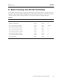
D Beam Focusing onto ATLAS Test Setups
In the "2000" filter mode optics of H8, the following current settings allow to change the focussing in the ATLAS region (H8A and H8B zones). The values given are for a +300 GeV/c beam scale the current values with momentum for any other momenta, including the sign.
Table D-1
Condition
Q16 (A)
Q17(A)
Q18(A)
Focus at MWPC5,6
265.2
-294.2
+265.2
Parallel in ATLAS tests
-263.6
-149.2
0
Focus 5.5m upstream of MSP
-236.0
-281.0
+263.0
Focus 5m downstream of MSP
-305.8
-218.0
0
Focus 10m downstram of MSP
-302.6
-207.0
0
Focus 20m downstream of MSP
-297.4
-198.2
0
Focus 30m dowstream of MSP
-293.6
-191.8
0
Focus 40m downstream of MSP
-290.4
-186.8
0
Focus at MNP17
288.4
-183.4
0
D
Beam Focusing onto ATLAS Test Setups
19
H8
SPS Beam Line
20
D
User Guide
23 May 2002
Beam Focusing onto ATLAS Test Setups
H8
SPS Beam Line
User Guide
23 May 2002
E Operation for “very low” Beam Energies
In order to allow the operation of the beam at energies lower than achieved before, the 6 main
vertical bending magnets (MBN’s) BEND1, 2, 3 and 4 have been recabled during the 1996/97
shutdown, in the following way (see also the figure attached):
Table E-1
previously
now (as of 1997)
B1
A
B1
A
B1
B
B2
A
B1
C
B2
B
B2
A
B1
B
B2
B
B1
C
B2
C
B2
C
B3
A
B3
A
B3
B
B4
A
B3
C
B4
B
B4
A
B3
B
B4
B
B3
C
B4
C
B4
C
This allows to run the beam with currents I(B1)=0, I(B3)=0 and I(B2)= 2I0, I(B4)=2I0 while previously all currents were set to I0.
As a result, the “point of deflection” is no longer in the centre of the 6 large bending magnets is
no longer in the middle of them but slightly offset. This has as a consequence that the beam is
vertically offset, e.g. by about + 30 mm in collimator C6 and is back on axis again only in collimator C9. The beamfiles for this very low energy running are specially marked in the comment
line and should not be changed without “additional thinking”.
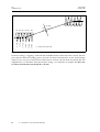
E.1 The “low energy wiggle”
The main vertical bending magnets in H8 are B1/B2 (+41 mr, 6 MBN magnets) near the end of
TCC2 (target area) and B3/B4 (-41 mr) at the top of TT82.
A general problem at low energy is the stability and precision of low currents in the recitifiers.
At high energy, two rectifiers are needed for B1/B2 as well as B3/B4. At low energy, higher stability and precision is obtained if one works only with one out of the two rectifiers, i.e. with
double the currents. In order to obtain a good beam transfer, the bending magnets have been recabled and the new layout is as follows.
E
Operation for “very low” Beam Energies
21
H8
SPS Beam Line
User Guide
23 May 2002
+ 30 mm
B3 B4 B4 B3 B3 B4
C6
29.45 m
23.79 m
18.13 m
11.32 m
5.66 m
0.0 m
B1 B2 B2 B1 B1 B2
<<-- distance from first B1
Figure E-1 The Low Energy Wiggle.
In the low energy “wiggling” mode, B1=B3=0 and B2, B4 are used at twice the current. This implies that the effective bending point is moved 0.75 meters downstream. As the total bending
angle is 41 mr, we get a vertical offset of the beam of -0.75*41=-30 mm at the level of B1/B2. The
magnification, i.e. the effect of the beam optics, being -1 at collimator C6 implies that the vertical offset of the beam at C6 should be + 30 mm.
22
E
Operation for “very low” Beam Energies
H8
SPS Beam Line
User Guide
23 May 2002
E
Operation for “very low” Beam Energies
23
H8
SPS Beam Line
User Guide
23 May 2002
This document has been prepared with Release 6.0 of the Adobe FrameMaker® Technical Publishing
System using the Technical Design Report template prepared by Mario Ruggier of the Information and
Programming Techniques Group, ECP Division, CERN, modified to suit the manual style by Ilias
Efthymiopoulos, SL/EA group.
To facilitate multiple author editing and electronic distribution of documents, only widely available
fonts have been used. The principal ones are:
Running text:
Chapter headings:
2nd, 3rd and 4th level headings:
Figure and table captions:
24
Palatino 10.5 point on 13 point line spacing
Helvetica Bold 18 point
Helvetica Bold 14, 12 and 10 point respectively
Helvetica 9 point