1
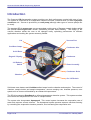
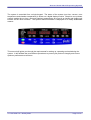
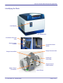
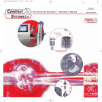
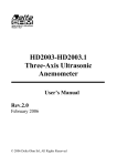
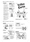
The Genevac DD- 4 & DD- 4X
Evaporation System
User Manual
Issue 3-1 – January 2009
Part Number 10-1471
Contents
Introduction...................................................2
Getting Started ........................................... 20
Safety .............................................................4
Switching on the Pump................................... 20
Switching on the Evaporator........................... 20
Lid Operation .................................................. 22
Safety Symbol ...................................................4
Genevac Evaporators and Combustible
Solvents .............................................................4
Electrical Safety.................................................4
Limitations of Use ..............................................4
Options ..........................................................5
Fixed Angle Rotors ............................................5
Dri-Pure™..........................................................5
AquaSpeed™ ....................................................5
Condenser Defrost ............................................5
Delivery and Installation ..............................6
Checking the Delivery........................................6
Arranging Commissioning .................................6
Training..............................................................6
Positioning the Evaporator ................................6
Pipe Connection Overview ................................6
Identifying the Parts...........................................7
Installing the Stystem ........................................8
Installation Variation ..........................................9
CVP Vacuum Pump...........................................9
Safe Loading of Rotor – General Document
......................................................................10
Nomenclature ..................................................10
Use of Correct Accessories .............................11
Adherence to Mass Limit .................................11
Safe Loading of Sample Holders into Swings .12
Balancing Sample Holders and Swings ..........13
Safe Loading for Fixed Angle Rotors ..............14
Safe Loading of Swing Rotor...........................15
Good Procedural Practice ...............................15
Rotors ..........................................................16
Fixed Angle rotors ...........................................16
Swing Rotor .....................................................17
Changing the Rotor .........................................18
To remove the rotor: ........................................18
To fit the rotor: .................................................18
Sample traceability ..........................................19
Evaporator Controls................................... 23
Using and setting the timer............................. 23
TIMED mode................................................... 23
NON-STOP mode........................................... 23
2 STAGE mode............................................... 24
VACUUM Display ........................................... 24
AquaSpeed ..................................................... 24
Rotor temperature control............................... 25
Chamber temperature control......................... 26
STATUS indicators ......................................... 27
Options ........................................................... 28
Dri-Pure .......................................................... 28
The Condenser ........................................... 29
Condenser Defrost.......................................... 29
Getting the Best from the System ............ 30
Routine Checks .............................................. 30
Tip for Improving System Performance .......... 30
Problem Prevention ................................... 31
Condensation.................................................. 31
TFA Creep ...................................................... 31
Bumping.......................................................... 31
Maintenance................................................ 32
Cleaning the Sample Holders and Swings ..... 32
Cleaning the Chamber, Rotor and Swings ..... 32
Scroll Pump .................................................... 32
Further Notes for CVP Pumps........................ 33
Planned Maintenance and Service................. 34
Moving the System ......................................... 34
Additional Equipment ................................ 35
Technical Data................................................ 36
EC Declaration of Conformity ......................... 37
Warranty Statement........................................ 37
Amendment Control Form .............................. 38
Useful Information...................................... 42
Genevac DD-4 & DD-4X Evaporating Systems
Introduction
The Genevac DD-4 evaporation system provides very high performance coupled with ease of use.
The system is comprised of an evaporation chamber and rotor, combined with a in-built cryopumpcondenser unit. Vacuum is provided by a scroll pump (although other types of vacuum pumps can
be used).
The standard DD-4 swung rotor can accommodate a wide range of Genevac sample holders whilst
the optional fixed angle rotor version (illustrated) provides extra flexibility. The design of the
vacuum chamber allows the rotor to be changed easily, optimising performance for different
applications and making the system extremely flexible.
Lid
Vacuum Port
CoolHeat Lamps
Condenser Inlet
Solid Rotor
Keypad / Display
Lid Release
Switch
Condenser
Rotor Assembly
Condenser Drain
Chamber
On / Off Switch
Solid-state case heaters and CoolHeat radiant lamps heat the chamber and samples. The control of
chamber, sample holder and sample temperature, vacuum ramping rate, chamber pressure, rotor
speed and run time are all handled by an onboard microprocessor.
The DD-4 incorporates RotoGuard, an infrared temperature detection system. This system monitors
and controls the temperature of the rotor or sample holders.
The system also incorporates Aquaspeed. This control system increases the evaporation rate of
water and aqueous solvent mixtures. The Aquaspeed system prevents aqueous solutions freezing
by controlling the evaporation chamber pressure, thus increasing the evaporation rate.
Page 2 of 42
10-1450 Issue 3-1 –January 2009
Genevac DD-4 & DD-4X Evaporating Systems
The system is controlled from a single keypad. The status of the system (run time, vacuum, rotor
temperature and chamber temperature) is shown on a digital display module. Simple to use up-down
controls enable the run time, rotor and chamber temperatures to be set in an instant and single push
buttons set the other functions. The system status information is displayed in an easily assimilated
manner.
This manual will guide you through the requirements for setting up, operating and maintaining the
system. It will facilitate the most efficient procedures to protect your product’s integrity and ensure
optimum performance at all times.
10-1450 Issue 3-2 – January 2009
Page 3 of 42
Genevac DD-4 & DD-4X Evaporating Systems
Safety
Safety Symbol
This safety symbol is used throughout this manual and is defined as follows:
Hazards that can be harmful to health, or lead to serious damage or injury.
Genevac Evaporators and Combustible Solvents
Please note it remains the responsibility of the user to consider safety when
evaporating any combustible solvents, and to place the system in a well-ventilated
environment. Genevac's position regarding evaporation of such solvents, particularly
with respect to the European ATEX directive, is available on our website or from your
local sales representative.
Electrical Safety
Important: the system must be earthed. This evaporation system is a safety class 1
product according to IEC classification. It must never be used with any interruption to
the safety earth conductor. It is an installation category II product and is intended to
operate from a normal, single-phase power supply.
This evaporator is designed for use in a degree 1 environment (no pollution, or only dry
non-conductive pollution).
Any maintenance or repair of this product must be carried out by Genevac personnel
(or approved representatives of Genevac) using only approved spare parts.
Limitations of Use
The Genevac DD-4 and DD-4X evaporation systems are unsuitable for use under the
following circumstances:
•
•
•
Page 4 of 42
With strong mineral acids such as HCl and HBr at all concentrations.
Evaporating diethyl ether and other similar low auto-ignition solvents.
For use as a pressure vessel.
10-1450 Issue 3-1 –January 2009
Genevac DD-4 & DD-4X Evaporating Systems
Options
Available options include the following
:
Fixed Angle Rotors
Easily interchangeable, high capacity, solid, fixed angle rotors optimise the system performance for
specific applications. This DD-4 option incorporates a software feature that compensates for the heat
flow characteristics of solid rotors, and provides ultimate flexibility by allowing the user to switch back
to conventional swung rotors.
Dri-Pure™
Avoid sample loss caused by cross contamination. The Genevac Dri-Pure system eliminates the
dangers associated with bumping, it reduces the vacuum chamber pressure over a predetermined
period of time and applies greater centrifugal acceleration to the samples.
AquaSpeed™
Significantly increase evaporation rates for water and aqueous solvent mixtures. The AquaSpeed
pressure control system holds the chamber pressure at 8mbar to prevent sample freezing.
Condenser Defrost
Optimise evaporation performance by rapidly defrosting high boiling point solvents in the condenser.
10-1450 Issue 3-2 – January 2009
Page 5 of 42
Genevac DD-4 & DD-4X Evaporating Systems
Delivery and Installation
Installation and commissioning by Genevac personnel is an option available with every new Genevac
DD-4 system. Installation instructions are provided should the commissioning option not be selected.
Checking the Delivery
Check the contents of the delivery, against the delivery note, as soon as possible. Notify Genevac
Ltd immediately if any parts are missing or damaged. (Refer to the back cover for contact details).
Arranging Commissioning
If your system is to be delivered separately, Genevac Ltd will contact you prior to delivery, to agree a
convenient date to commission your system.
Training
Commissioning normally includes training in the basic operation of the system.
The DD-4 evaporator must not be operated by personnel who lack the training or
experience to comprehend the hazards that can arise when using the system. Personnel
without such training require thorough instruction. These operating instructions should
form the basis of this instruction.
Positioning the Evaporator
The evaporator must be sited on a level and sturdy work-surface. Position the evaporator
at least 300mm away from the edge of a bench and the same distance clear of any
breakable objects or areas where entrapment could occur. If this positioning requirement
is impractical then the evaporator should be bolted to the bench or trolley, by its five
mounting feet, using M10 high tensile bolts. Consult Genevac for advice on any other
positioning requirements.
Pipe Connection Overview
Page 6 of 42
10-1450 Issue 3-1 –January 2009
Genevac DD-4 & DD-4X Evaporating Systems
Identifying the Parts
Lid Release
DD-4 Evaporator
Condenser Vacuum
Inlet
Control Cable
Socket
Condenser Drain
Outlet
Pump Vacuum Inlet
Pump Control Box
Catch-pot
Assembly
Pump Control
Cable Socket
Mains Power
Connector
10-1450 Issue 3-2 – January 2009
Scroll Pump
Page 7 of 42
Genevac DD-4 & DD-4X Evaporating Systems
Installing the Stystem
These instructions refer to the installation of a DD-4 or DD-4X evaporator with a scroll pump. Details
follow to show differences that may be encountered on different build variants.
Note: The power to the evaporator is delivered via the pump control cable.
Fit the pump control box to the scroll pump using the connectors, clamps and fasteners supplied.
Fit the pump exhaust outlet and catch-pot assembly to the pump.
Place the evaporator and scroll pump in their intended location. Ensure there is enough space above
the evaporator for the lid to open.
Connect the 16KF convoluted vacuum tube to the pump vacuum inlet via a 16KF to 25KF reducer,
appropriate clamps and centre rings. Connect the other end of the convoluted vacuum tube to the
condenser vacuum inlet on the back of the evaporator.
Connect a length of exhaust tube to the spigot on top of the pump catch-pot. Connect the other end
of the exhaust tube to a suitable laboratory fume extraction system.
Connect the pump control cable to the pump control cable socket. Connect the other end of the
control cable to the control cable socket on the back of the evaporator. Note: The pump control
cable has a male connector at one end, a female at the other end and only connects to the
corresponding sockets in the correct orientation. To connect the control cable, push the connector
into the socket and twist the knurled grip clockwise until it clicks into place.
Connect a drain pipe (not supplied) to the condenser drain outlet. Place the other end of the drain
pipe in a suitable waste solvent container (not supplied). Ensure the end of the drain pipe cannot be
submerged in the waste solvent.
Connect the mains power cable to the pump mains power connector. Connect the mains power
cable to a suitable mains power outlet.
The system is now ready to switch on. Carry out a safety inspection before operating the system.
Page 8 of 42
10-1450 Issue 3-1 –January 2009
Genevac DD-4 & DD-4X Evaporating Systems
Installation Variation
CVP Vacuum Pump
Connect the CVP pump in the same way as the scroll pump, the following additional instructions
apply.
Connect a short length of exhaust tubing to the pump exhaust outlet and seal with a pipe clamp.
Connect the other end of the short tube to a pump catch pot spigot and seal with a pipe clamp.
Oil Filler Access Cover
Pump vacuum inlet
Pump exhaust outlet
Power on / off Switch
Pump Ready Lamp
CVP Pump
Connect the other end of this exhaust tubing to the condenser exhaust inlet on the back of the
evaporator.
The pump must have an adequate supply of cooling air and a minimum 300mm of free
space adjacent to the heat exhaust. Do not place the pump in a space (such as a
cupboard) which has restricted airflow.
Fill the pump with the correct type of silicon oil before operating the system. Refer to the section
entitled: Further Notes for CVP Pumps for details.
Note: Early build versions of the CVP pump require a different pump control cable which connects to
the pump via a plastic connector.
Do not attempt to exchange a CVP pump for a scroll pump. This operation requires a set-up in the
system software that may only be carried out by Genevac Service personnel or a trained
representative of Genevac.
10-1450 Issue 3-2 – January 2009
Page 9 of 42
Genevac DD-4 & DD-4X Evaporating Systems
Safe Loading of Rotor – General Document
Genevac are obliged to include the following information in its entirety, irrespective of
the system type.
As with all centrifuges, Genevac centrifugal evaporators must be loaded correctly to remove the risk
of damage. Failure to correctly load a system can lead to unrecoverable loss of samples and
damage to the system. This guide is intended for new users and also as a reminder for more
experienced users. The principles outlined apply to all Genevac evaporators.
The following instructions deal with various aspects of loading:
•
•
•
•
•
Use of correct swings and sample holders
Observation of weight limits
Safe loading of sample holders into swings
Balancing of swings and sample holders
Good procedural practice
Nomenclature
Some Genevac systems feature fixed rotors which have angled holes for individual tubes or
holders. The following instructions are primarily concerned with the more common swung rotors.
The new range of Genevac sample holders (blue in colour) include integral swing holders such as the
example shown.
Integral Swing / Tube Holder
Tube Holder and Side-Bridge Swing
Sample holders requiring a separate swing (or bucket) may also be used.
Each of these swing types lifts straight out of the rotor. The ideal swing type depends on the sample
holder required. A large range of sample holders is available. Load the tubes, vials, beakers or
flasks into the sample holders, then place the sample holders in the swings.
Page 10 of 42
10-1450 Issue 3-1 –January 2009
Genevac DD-4 & DD-4X Evaporating Systems
Use of Correct Accessories
Genevac supply a wide range of sample holders to cover a variety of plate, tube, vial or flask formats.
Where no holder is available, custom units can be made. To ensure that bespoke holders are
suitable and approved for use, new sample holders may be designed in collaboration with the
Genevac R&D department.
Criteria for approval:•
•
•
•
•
Mass within prescribed maximum limit.
Matched sample holder mass within a set.
Correct centre of gravity.
Good thermal conductivity.
Correct hole, form and size, tolerance to reduce risk of tube or vial breakage under centrifugal
acceleration.
All Genevac holders are designed with these constraints in mind. 3rd party accessories may not be.
With the exception of microtitre plates, do not load any non-Genevac holders into a system without
gaining approval from Genevac. Failure to comply may result in unrecoverable loss of samples,
severe damage to equipment and invalidation of the warranty.
All swings and holders must be approved for the Genevac system in which they are used
(applicable particularly where Series I and Series II evaporators are used within the same
laboratory). For example, some sample holders designed for use in Series II systems,
might appear to fit in a Series I system, but would exceed the weight limitations. If in doubt always
consult Genevac before using such holders.
There are also instances where a sample holder intended for one tube or vial, becomes unsuitable if
used with something else, even though it might appear that the alternative tube fits. The Genevac
Accessories Brochure indicates the maximum tube length that each holder is designed to take.
Always adhere to these limits.
Similarly, sample holders intended for use in a Side-Bridge swing must not be used in an Open
swing, even though they might appear to fit. The Accessories Brochure has a note: For use in SideBridge Swing by these items, but if in doubt, ask Genevac.
Please note that some (not all) of the Bohdan Miniblock system sample holders significantly exceed
the mass limitations of a Genevac system. If you plan to use Bohdan Miniblocks in a Genevac
system, please contact Genevac for a list of the relevant weights.
Adherence to Mass Limit
The total mass that can be loaded onto each position of a Genevac swung rotor. This mass includes:
•
•
•
•
The swing
The sample holder
The tubes or vials
The sample solutions
Do not exceed mass limit under any circumstances. In most cases, with normal solvent volumes,
sample holders on sale from Genevac fall within the mass limit for a series II system. If in any doubt,
load up a full swing and weigh it.
10-1450 Issue 3-2 – January 2009
Page 11 of 42
Genevac DD-4 & DD-4X Evaporating Systems
Safe Loading of Sample Holders into Swings
This information is applicable where Series 1
and series II equipment is used in the same
laboratory.
Sample Holder rotated
There are two possible ways in which a sample holder may
be miss-loaded into an older type of swing. One is to
rotate the sample holder such that its corners rest on the
edges of the swing. The other is to place the sample
holder so that one side rests on the edge of the swing.
Both these modes of miss-loading are possible with a
Series 1 open or standard swing, but are virtually
impossible with a Series II swing. Care must still be taken
when loading the samples.
Sample Holder correctly
seated
The Series 1 design is easy to distinguish. The corners
are not welded.
Sample Holder on edge of
swing
The Series II swing has angled sides and rounded corners
that are welded.
Genevac offer an option to upgrade to the new range of
sample holders and swings. This upgrade permanently
avoids the possibility of mis-loading..
Sample Holder correctly
seated
Page 12 of 42
10-1450 Issue 3-1 –January 2009
Genevac DD-4 & DD-4X Evaporating Systems
Balancing Sample Holders and Swings
Opposite pairs of swings must be balanced within 10g and the swings must be of the same
type and version. Please note that there are several versions of Side Bridge Swings in
circulation with a static weight ranging from 375g to 445g. Place swings of the same static
weight, in diametric opposition on the rotor; ideally use the same version of swings in all
four positions of each rotor level.
Genevac systems have some inbuilt tolerance for imbalance, and a safety system which stops the
rotor if the out-of-balance is unacceptably high. However, to minimise noise nuisance and wear-andtear the balance limit should always be observed.
Real loads may be balanced using Dummy samples. They must be of a similar solvent composition.
For example, do not balance 200g of 50 / 50 - Water / Acetonitrile with 200g of water. Partway
through the run, the acetonitrile evaporates but the water remains, resulting in an imbalance of 100g.
Note that with a system such as the Fast-StackTM swing, balancing is slightly more complex.
Suppose a Fast-StackTM Deepwell swing is used with two 96 well microtitre plates, 2ml per well. In
one swing, the lower microtitre plate is empty, the upper microtitre plate is full, 1.8mls per well. On
the other swing, the reverse is true.
The two swings now weigh the same. However, if placed opposite each other in on a rotor, would be
imbalanced. This is because when the swings rotate to their operating attitude, the centre of mass of
one is at a different radius to that of the other.
Swings are the same weight but not balanced
It is also preferable to run the evaporator with all four swings fitted to each level of the rotor. If there
are only enough samples to fill two swings, it is better to distribute the samples into four holders (or,
at least, place two empty holders in the rotor). This reduces the mechanical stress on the rotor and
helps to distribute the heat flow evenly between the samples.
10-1450 Issue 3-2 – January 2009
Page 13 of 42
Genevac DD-4 & DD-4X Evaporating Systems
Safe Loading for Fixed Angle Rotors
Interchangeable fixed angle rotors are available for various tube diameters.
Select the FIXED ROTOR option on the control panel.
Check the rotor retaining nut (T-handle) is secure before loading samples.
Do not use tubes that exceed the maximum tube length specified on the label. The rotors
are configured with concentric rings of tube holders with the capacities specified on the
rotor label. Use only the tubes specified on the label; the tube should slide freely into the
rotor.
The system will operate with up to 85g of imbalance. Load the solid rotor in a systematic manner, to
avoid exceeding this level of imbalance. Balance each sample tube by loading a similar tube in the
diametrically opposite position.
Rotor imbalance is `affected by the size of tube and the volume and density of the solvent being
loaded. For instance, a 150 x 24 mm tube loaded with 30 ml of water, weighs approximately 72g. A
tube with the same volume of chloroform weighs 86g. This would be enough to imbalance the rotor if
loaded singly or in an unsymmetrical manner.
Load the rotor in a symmetrical and balanced manner
If a tube is loaded here,
then also load a similar tube here
Page 14 of 42
10-1450 Issue 3-1 –January 2009
Genevac DD-4 & DD-4X Evaporating Systems
Safe Loading of Swing Rotor
Deselect the FIXED ROTOR option (press the button on the control panel if the option is installed)
when using a swung rotor.
Samples in the chamber are subjected to accelerations of up to 500G with a maximum load capacity
of 1.5 kg per swing. The load capacity includes tubes, solvent, sample, sample holder and swing.
Always observe the following Precautions
• Check the rotor retaining nut (T handle) is secure before
loading samples.
• Never exceed the maximum load capacity of 1.5 kg per swing.
• Locate tubes correctly in tube holders.
• Locate sample blocks correctly in sample swings.
• Load two or four tube holders in opposite and balanced
configurations.
• Distribute tubes in sample holders symmetrically.
• Balance pairs of sample holders that are loaded opposite each
other to within 10g (approximately).
Rotate the rotor by hand and check that all tube holders and plates
are correctly located and swing freely. Use only the sample
holders supplied with the system, or that are specified for use with
the system. Never use non Genevac approved sample holders.
Genevac Ltd will accept no responsibility for any loss or damage
incurred by improperly or excessively loaded rotors.
Good Procedural Practice
Finally, there are a few general rules for safe operation of a system:
•
•
•
•
•
Only permit users, familiar with all the issues outlined in this document, to operate the equipment.
Only load swings and sample holders that are approved by Genevac.
The same user should be responsible for loading and starting the system.
Never leave the system unevenly loaded with the door closed. Someone may start it.
Never start, or restart a system without checking it is evenly loaded, all sample holders are
correctly seated and all holders swing freely.
Miss-loading may result in unrecoverable sample loss, damage to equipment, and could
void the warranty.
10-1450 Issue 3-2 – January 2009
Page 15 of 42
Genevac DD-4 & DD-4X Evaporating Systems
Rotors
Fixed Angle rotors
The fixed angle rotor is fabricated with individually angled holders to take test tubes and vials. The
swing rotor has pivoting buckets that take the sample holders.
Specification
Tube Diameter x Length (where specified) x Quantity
Part number
13 mm tube x 96 (100 – 150mm long)
70-0227
16 mm tube x 96 (100 – 150mm long)
70-0228
18 mm tube x 72 (100 – 150mm long)
70-0229
20 x 100mm tube x 72
70-0230
20 x 150 mm tube x 48
70-0340
24 to 25 mm tube x 48 * (100 – 150mm long)
70-0231
28.5 mm tube x 40 (100 – 150mm long)
70-0232
*
Compatible with Radleys Carousel Threaded Tubes
Page 16 of 42
10-1450 Issue 3-1 –January 2009
Genevac DD-4 & DD-4X Evaporating Systems
Swing Rotor
The buckets swing up through 90° as the rotor speed increases and return to the horizontal position
as the rotor speed decreases to stop.
Specification
Part number
Centre Line rotor plate for use with the Genevac range of swings and
holders.
70-0220
Supplied with 4 x standard buckets (70-0213) when purchased with
complete unit (Optional)
10-1450 Issue 3-2 – January 2009
Page 17 of 42
Genevac DD-4 & DD-4X Evaporating Systems
Changing the Rotor
To remove the rotor:
1.
Remove the samples and sample holders (if fitted).
2.
Undo the retaining nut by turning the T-handle counter-clockwise whilst holding the rotor
stationary.
3.
Lift the rotor using the T-handle.
To fit the rotor:
1.
Lower rotor carefully into the chamber using the T-handle
2.
Tighten the retaining nut by turning the T-handle clockwise.
Note: If retaining nut rotates freely, the rotor has not engaged correctly. Lift the rotor approximately
50mm (2”) using the T-handle. Turn the rotor slightly and repeat steps 1 and 2 above.
3.
Tighten the retaining nut securely.
4.
Manually rotate the rotor to ensure that it runs freely.
Page 18 of 42
10-1450 Issue 3-1 –January 2009
Genevac DD-4 & DD-4X Evaporating Systems
Sample traceability
Each fixed angle rotor has a label that indicates the tube number in each ring.
Whilst this aids loading, it is recommended to keep a separate log of sample positions when
dissimilar products are loaded. Alternatively, use a suitable label to identify the samples.
Note: Sample labels can affect the performance.
10-1450 Issue 3-2 – January 2009
Page 19 of 42
Genevac DD-4 & DD-4X Evaporating Systems
Getting Started
Switching on the Pump
Connect the pump to the mains and switch on the mains.
Switch on the pump power switch.
Note: The pump does not start until the evaporator is switched on.
Scroll pump power switch
CVP pump power switch
Switching on the Evaporator
Switch on the evaporator power switch.
There is a short delay while the microprocessor completes its boot
up sequence.
Evaporator power switch
Page 20 of 42
The system is now in stand-by mode.
10-1450 Issue 3-1 –January 2009
Genevac DD-4 & DD-4X Evaporating Systems
Press the START key to start the system:-
•
•
•
•
•
The pump starts.
All the display LEDs light momentarily to check operation, the display then shows the RUN
TIME, VACUUM, ROTOR TEMP and CHAMBER TEMP.
The ready light illuminates in red to show there is power to the system.
The condenser starts after a delay of approximately three minutes.
After a further delay, the ready light turns first to amber to indicate when the pump reaches
operating temperature (CVP pump only). The ready light then turns green to indicate when the
condenser reaches its operating temperature.
The evaporator is now ready for use.
The following notes provide basic instructions for starting up the evaporation system. Refer to the
relevant sections of this manual for detailed information on specific steps.
10-1450 Issue 3-2 – January 2009
Page 21 of 42
Genevac DD-4 & DD-4X Evaporating Systems
Lid Operation
An electromechanical lock secures the lid automatically. Press the button on the evaporator front
panel to release the lock.
Lift the lid manually. It stays in position when opened to more than 45°. The lid closes under its own
weight when lowered.
Note: The lid remains locked and cannot be opened whilst the rotor is spinning or the system is
under vacuum.
Page 22 of 42
10-1450 Issue 3-1 –January 2009
Genevac DD-4 & DD-4X Evaporating Systems
Evaporator Controls
The DD-4 keyboard controls and displays are designed for ease and simplicity in use.
Using and setting the timer
During a run the RUN TIME can display either the elapsed time, E or the remaining time, R. Press
the up and down keys simultaneously, to toggle between the elapsed and remaining times.
Up and down keys
MODE key
Press the MODE key to select one of three possible operational modes. The selected mode is
indicated by an illuminated LED.
TIMED mode
Use the TIMED mode when a pre-determined run duration is required with Coolheat.
duration prior to or during a run.
Set the
To set the run duration in TIMED mode use the up and down keys to input the desired run time.
Press down and hold either key for coarse setting. Press either key once for fine setting. A
maximum time of 99 hours 59 minutes and a minimum time of 1 minute can be set. Elapsed or
remaining time can be displayed in this mode.
NON-STOP mode
Select the NON-STOP mode to run the evaporator continually with the Coolheat facility enabled, the
evaporator runs until the STOP key is pressed. This mode is useful if the evaporation time for a
particular solvent or solvent mixture is unknown. Only the elapsed time is displayed when operating
in this mode.
10-1450 Issue 3-2 – January 2009
Page 23 of 42
Genevac DD-4 & DD-4X Evaporating Systems
2 STAGE mode
Select the 2 STAGE mode to run the evaporator for a predetermined period with the Coolheat facility
enabled. After this period, the Coolheat facility is disabled and the system continus to run at full
vacuum until the STOP key is pressed. Elapsed or remaining time can be displayed during the first
stage of this mode, but only elapsed time during the second stage.
This mode is particularly useful for lengthy evaporation times, when it may be necessary to run the
system overnight.
Since the Coolheat facility is disabled after the predetermined period, sample temperatures
may reach the temperature to which the chamber has been set.
VACUUM Display
The vacuum display indicates the absolute pressure within the evaporation chamber, in millibar
(mbar). As the vacuum pump evacuates the system, the value continually changes, until the full
vacuum capability of the system is reached.
The key below the vacuum display enables the AQUASPEED function.
AquaSpeed
The AQUASPEED system was developed to significantly improve the system performance when
evaporating water or water mixtures. It limits the pressure in the evaporation chamber to 8 mbar,
Press the AQUASPEED key to select this facility, a lamp illuminates to indicate when it is enabled.
The function can also be used simultaneously with the optional DRI-PURE facility.
Page 24 of 42
10-1450 Issue 3-1 –January 2009
Genevac DD-4 & DD-4X Evaporating Systems
Rotor temperature control
The maximum rotor temperature is monitored and controlled by the RotoGuard infrared temperature
detection system. The setting of this control determines the temperature at which the Coolheat
lamps are disabled. For instance, if the temperature is set at 30°C, the Coolheat lamps are turned off
when RotoGuard senses a temperature of 30°C.
Note: This control defaults to the previously entered settings from power up.
Press both keys simultaneously to change the setting, a SET prompt starts to flash. Use the up and
down keys to set the required rotor temperature.
Press and hold either key down for coarse setting or press once for fine setting. The value is
accepted and the display reverts to ACTUAL after a short period.
Press either key to display the set temperature at any time. The display automatically reverts to the
actual setting after a short period. Use the same procedure to reset the temperature setting during a
run.
10-1450 Issue 3-2 – January 2009
Page 25 of 42
Genevac DD-4 & DD-4X Evaporating Systems
Chamber temperature control
This control displays and controls the temperature of the chamber. If this is set above ambient, prior
to a run, the run will not start until the chamber temperature preheats to the set value.
A flashing point, between hours and minutes, on the RUN TIME display, indicated when preheat is
operating. Press both keys simultaneously to change the setting. The SET prompt starts flashing,
press the up and down keys to set the desired chamber temperature. Hold either key down for
coarse setting or press once for fine setting.
The value is accepted and the display reverts to ACTUAL after a short period. Press either key to
display the set temperature at any time. The temperature setting can be changed during a run using
the same procedure.
Page 26 of 42
10-1450 Issue 3-1 –January 2009
Genevac DD-4 & DD-4X Evaporating Systems
STATUS indicators
The system status is indicated by a row of lamps on the far left of the display. The SYSTEM READY
lamp illuminates in red when the system is first switched on. All other lamps are off.
Press the START key to start the system, the rest of the display illuminates and the SYSTEM
READY lamp remains red until the condenser (and, where relevant, the CVP pump) is ready.
Note: From cold, the system may take approximately 10 minutes to reach operating temperature.
The SYSTEM READY lamp turns green to indicate when the condenser (and pump) are at operating
temperature. The evaporator may be loaded, set, and started before the ready light turns green, in
which case the run commences (after preheat if required) when the ready lamp turns green.
The ROTOR SPINNING lamp turns green.
Note: It is not possible to open the lid once the rotor starts rotating.
If the system detects an excessive out of balance, the green IMBALANCE lamp illuminates and the
run terminates. In such cases, press the STOP button after the rotor stops (this shuts down the
evaporator) and correct the source of the imbalance.
The Coolheat indicator lamp illuminates when the lamps are on.
10-1450 Issue 3-2 – January 2009
Page 27 of 42
Genevac DD-4 & DD-4X Evaporating Systems
Options
A number of options are available with purchase of a new system. There are four additional buttons,
on the control panel, for those options.
These options are:
•
Condenser defrost
•
Dri-Pure
•
Fixed Rotor
Dri-Pure
DRI-PURE reduces the vacuum over a predetermined period, at the end of which the full vacuum
capability of the vacuum pump comes into effect. This feature is useful in preventing bumping (the
violent boiling of solvents) which can cause cross contamination be to solvents being expelled.
Bumping can also cause products to be deposited on the glass lenses of the Coolheat lamps, which
reduces system efficiency and may eventually lead to lamp glass breakage.
Press the DRI-PURE key to select this feature. A lamp will illuminate to indicate that the feature is
enabled.
Note: During the DRI-PURE cycle (approximately 40 minutes) the Coolheat function is disabled.
Page 28 of 42
10-1450 Issue 3-1 –January 2009
Genevac DD-4 & DD-4X Evaporating Systems
The Condenser
The condenser starts automatically a short time (approximately 3 minutes) after the evaporator is
switched on. There is a further short delay before the condenser reaches operating temperature.
Drain the condenser (defrost first if necessary) before each run and at the end of each day.
Condenser Defrost
The internal condenser requires minimal maintenance. For best evaporation performance the
condenser should be drained between each run. However, under certain circumstances it may be
more practical to do this every alternate run.
If high boiling point solvents are used (e.g. DMF or DMSO) it is necessary to defrost the condenser
prior to draining. Press the DEFROST key to initiate the defrost cycle. A lamp illuminates red. On
completion of defrost cycle the lamp turns green.
Note: Do not defrost the condenser if the solvent does not freeze.
If the Condenser Core Temperature option is fitted, the lamp turns green when the temperature in
the pot indicates that all solvents are liquid. The condenser remains at this temperature until
DEFROST is deselected.
If the Condenser Core Temperature option is not fitted, the lamp turns green to indicate that the 2
hours defrost duration is complete. This is the maximum time that the system requires to defrost if
the condenser is full and frozen. The defrost continues mode continues to heat the solvent, drain the
solvent at the first opportunity and open the drain valve to drain the condenser.
Drain valve plunger
Drain outlet
Take care when opening the evaporator lid. Solvent vapour may build up in the evaporation
chamber during the condenser defrost.
Ensure the chamber drain is connected to a suitable waste solvent container before
operating the drain valve plunger.
Open the lid and lift the drain valve plunger to open the drain valve.
Note: The condenser capacity is 2 litres.
10-1450 Issue 3-2 – January 2009
Page 29 of 42
Genevac DD-4 & DD-4X Evaporating Systems
Getting the Best from the System
Routine Checks
For high boiling point solvents such as DMSO, NMP, DMF and DMI the best evaporation rates are
achieved at pressures lower than 0.5 mbar. Carry out the following checks regularly to ensure
optimum vacuum performance.
•
•
•
•
Check security of all clamped joints.
Deftost (if necessary) and drain the condenser pot before every run.
Check the pump exhaust catch pot regularly and empty as necessary.
Keep a log of the time taken to reach full vacuum. Use this to indicate any deterioration of
performance due to seal ageing and wear.
Tip for Improving System Performance
Increase evaporation speed for high boiling point solvents by pre heating the aluminium sample
holders.
Page 30 of 42
10-1450 Issue 3-1 –January 2009
Genevac DD-4 & DD-4X Evaporating Systems
Problem Prevention
Condensation
Solvent condensation within the evaporator occurs when the chamber walls are cooler than the
solvent vapour. This is most likely to occur with high boiling point solvents such as NMP, DMI,
DMSO and possibly DMF.
Pre-heat the evaporator chamber to prevent this happening. To do this, enter the Run Data screen,
set the Minimum Chamber Temperature field to 40°C and start the run. The chamber takes
approximately 20 minutes to reach this temperature. Note the CoolHeat lamps do not operate during
this pre-heating cycle.
If condensation occurs unexpectedly, switch off the lamps by entering 0 into the Heat off Elapsed
Time field on the Run Data screen.
Do not pre-heat the chamber when evaporating volatile solvents such as TFA, acetonitrile or
methanol.
TFA Creep
TFA exhibits the property of creeping. This is the movement of the TFA in liquid phase up the inside
of the tubes, vials or microtitre plates. Problems can arise if solvent containing product is deposited,
in this way, on the top face of plates. Solvent and product may also be thrown onto the side of the
chamber and the Quartz glass lamp windows as the rotor spins.
Whilst the solvent evaporates, the product becomes carbonised by the heat from the lamps and
forms sites where crack propagation can occur. Inspect the lamp glass at regular intervals and clean
with a lint free cloth and acetone.
Contact Genevac Service if the contamination becomes excessive and carbonised as shown.
A range of specialised sample holders is available to protect the Quartz lenses. Contact Genevac
Sales for details.
Bumping
Bumping can also cause product to deposit on the glass lenses as previously described. It is
unpredictable and may occur with any solvent or mixture, it is also a potential source of cross
contamination between samples.
Avoid bumping by selecting the Dri-Pure option from the Pressure Control Regime drop down
menu on the Run Edit screen. This option sets a high rotor speed and avoids super-heating the
samples by reducing the pressure in the vacuum chamber by gradual increments. Evaporation
begins progressively and samples are contained due to the higher centrifugal acceleration.
10-1450 Issue 3-2 – January 2009
Page 31 of 42
Genevac DD-4 & DD-4X Evaporating Systems
Maintenance
Refer to the section entitled: Getting the Best from Your System for details of routine maintenance
checks. This section describes some further proactive maintenance procedures.
Excessive build up of debris on the pivoting faces of the sample swings and rotor can
cause the sample swings to stick in the out position when the rotor stops. This can cause
unrecoverable sample loss.
Cleaning the Sample Holders and Swings
Regular inspection and maintenance of swings and sample holders should be performed at least
monthly. The following inspection routine is mandatory following any tube breakage or solvent
spillage. Never use wet swings or holders in an evaporator.
Visually inspect the sample holders monthly. Clean off any debris, especially in the sample holder
wells as this may cause high points that lead to stress in the glassware, resulting in breakage. The
main cause of repeat glassware breakage is fragments from a previously broken tube. Solvent can
stick the glass fragments to the holder making it difficult to remove. Residual solvent or sample
material must be cleaned off.
Superficial surface damage (e.g. scratches) do not affect the performance of a holder or swing.
However, if there is any structural damage (if any part of the holder, swing or rotor is bent or
deformed) do not use it. Contact Genevac Service for evaluation.
Cleaning the Chamber, Rotor and Swings
TFA creep can cause debris deposits on the inside of the chamber and on the Quartz glass, see
Problem Prevention for details. Routinely inspect the inside of the chamber and quartz glass for
build up of debris and potential contaminants. Check the sample swings are able to move freely.
Clean the Quartz Glass using a suitable solvent (such as methanol or acetone) and a lint free cloth or
paper towel. Clean the swings and rotor in the same manner. Take care to avoid solvent contact
with the outside paintwork and accessories of the chamber.
Scroll Pump
Check the pump exhaust catch pot regularly and empty it as necessary.
maintenance is required.
Page 32 of 42
No further routine
10-1450 Issue 3-1 –January 2009
Genevac DD-4 & DD-4X Evaporating Systems
Further Notes for CVP Pumps
Check the pump oil level weekly. Ensure the oil level is within the notch on the dipstick. Top it up if
necessary using the correct grade of silicon oil.
Correct Oil level – centre of dipstick notch
Pump Type
CVP100/CP
CVP100/CPC
Correct oil
SCF025
Crylin 614
Part Number
AS1616 (1 litre)
AC2310 (1kg)
Do not apply vacuum to a recently defrosted condenser containing traces of liquid DMF, DMSO or
NMP. This is likely to cause pump oil contamination.
The pump must have an adequate supply of cooling air and a minimum 300mm of free space
adjacent to the heat exhaust. Do not place the pump in a space with restricted airflow, such as a
cupboard.
10-1450 Issue 3-2 – January 2009
Page 33 of 42
Genevac DD-4 & DD-4X Evaporating Systems
Planned Maintenance and Service
Whilst every effort is made to design and manufacture the DD-4 and DD-4X evaporation systems to
the highest build quality and to provide assured reliability, there will be some degree of wear and
ageing of the seals and bearings of the chamber, condenser and pump. The extent of wear and
ageing depends on the utilisation of the system, the severity of temperature cycling and the nature of
the solvents used.
Some solvents may eventually cause pin-hole corrosion in the connecting tubes, resulting in a
decline in performance. A gradual decline in system performance may not be noticed if it occurs over
a period of time. Monitor the system performance by keeping a weekly log of the time taken for the
system to reach full vacuum and the full vacuum achieved.
In order to maintain peak performance and avoid costly and unscheduled down time, Genevac
strongly recommend implementing a schedule of planned maintenance. Changing parts in the field is
complex and demands a high level of skill. To this end, Genevac offers a range of preventative
maintenance, service and breakdown contracts.
Moving the System
Refer to the section entitled: Positioning the Evaporator. Refer also to the following notes if it is
necessary to move a system to a new location. Address the following key points before moving a
DD-4 or DD-4X evaporation system.
•
Clear sufficient bench of fume cupboard space to accommodate the system at the new location.
•
Ensure there is access to a power supply (two separate mains sockets are required).
•
Ensure there is adequate ventilation.
•
Make provision for the drainage of waste solvents.
•
Make provision for the extraction of the pump exhaust.
•
Defrost and drain (and if possible, flush) the condenser pots.
•
Remove the sample swings from the rotor.
•
Remove and retain all the clamps, seals, tubes, cables and instructions.
Page 34 of 42
10-1450 Issue 3-1 –January 2009
Genevac DD-4 & DD-4X Evaporating Systems
Additional Equipment
Genevac supply a range of swings and sample holders which may be utilised to adapt existing
systems for new applications. All sample holders are of a solid aluminium construction and are
black anodised to improve heat absorption. Solid aluminium tube holders provide even heat
distribution for uneven drying loads. Maximum contact areas provide good physical support,
optimum heat transfer and even heat distribution
The following accessories are an example of the many ways in which Genevac can assist in
developing your system for the future.
For further information, or to discuss any requirements, please call Genevac Sales using the contact
details on the back cover of this User Manual.
Side Bridge
FastStack for deep well plates
One piece holder for 50mlTubes
10-1450 Issue 3-2 – January 2009
FastStack for shallow well plates
Flask holder
Sample Genie
Page 35 of 42
Genevac DD-4 & DD-4X Evaporating Systems
Technical Data
Mechanical data
Max rotor speed
Max force
Drive system
Operational imbalance
Max load
IR lamps number
Weight
Vacuum System
Pressure resolution
Vacuum control
Dri-Pure
Auto vacuum vent valve
Rapid defrost
Ultimate system vacuum
Vacuum pump - CVP
Weight
Maximum vacuum
Flow rate
1300 standard
1800 Dri-Pure
300-500G
Direct
85g
4x1.5kg @ 500G
2
109 kg (HT4 SII)
118 kg (HT4X SII)
1-1000 mbar
1-1000 mbar
Yes
Yes
Yes
0.4 mbar
52 kg
0.15 mbar
3.6 m3h-1
Electrical
Power Supply single phase 9A
Operating Environment
Ambient temperature
Relative humidity
Altitude
Page 36 of 42
Condenser
Temperature max low
Temperature max high
Vacuum pot capacity
Exhaust pot capacity
Condenser level detector
Condenser chamber
Condenser drain valve
Vacuum Pump - Scroll
Weight
Maximum vacuum
Flow rate
Dimensions
Evaporator (W xD x H)
-45°C ( HT4 SII)
-50°C (HT4X SII)
+60°C
1.5 litres (HT4 SII)
2.3 litres (HT4X SII)
0.4 litres
No
316 Stainless steel
Stainless steel / PTFE
28kg
0.15 mbar (50Hz)
0.12 mabr (60Hz)
3.6 m3h-1
Scroll pump
CVP pump
535 x 642 x 583mm (DD-4)
585 x 642 x 583mm (DD-4X)
530 x 305 x 398
540 x 290 x 405
Storage Environment
Ambient temperature
Relative humidity
Altitude
-10°C to 60°C
10 – 80 %
Sea level to 12,000m
230V, 50Hz
208V, 60Hz
15°C to 30 °C
10 – 60 %
Sea level to 12,000m
10-1450 Issue 3-1 –January 2009
Genevac DD-4 & DD-4X Evaporating Systems
EC Declaration of Conformity
We Genevac Limited, declare that these products: DD-4 & DD-4X evaporating systems, Comply
with the relevant Essential Health and Safety Requirements of the European Machinery Directive
(98/37/EEC), the EMC Directive 89/336/EEC, and the Low voltage Directive 73/23/EEC.
Conformity is demonstrated by compliance with the following specifications: EN 60204-1:2006
EN 249: 1992
EN 1088: 1995 + A1:2007
BS EN ISO 12100 pts 1 & 2:2003
BS EN 50082-1: 1998
BS EN 61010-1:2001
Safety of machinery– Electrical equipment of machines-Pt 1
General Requirements.
Safety of machinery– Safety distances to prevent danger zones
being reached by upper limbs.
Safety of machinery. Interlocking devices associated with
guards. Principles of design and selection.
Safety of Machinery - Basic concepts, general principles for
design.
Electromagnetic compatibility-Generic immunity standard.
Safety requirements for electrical equipment for measurement,
control and laboratory use, general requirements.
Warranty Statement
This product is guaranteed for period of 12 months from the date of delivery to site. In the unlikely
event of any defect arising due to faulty materials or construction resulting in system failure, the unit
will be repaired free of charge. This includes all labour and component costs incurred.
This warranty is subject to the following provisions:
1. System must be sited, installed and operated in accordance with operator instruction manual.
2. The system is only used for purpose it was sold, and in accordance with Genevac published
compatible solvent list.
3. The regular cleaning and preventative maintenance schedule must be adhered to as detailed in
operator’s manual.
4. The warranty does not cover accidental damage, misuse, modifications or inappropriate repair by
untrained personnel.
5. The warranty does not cover the following consumable items: Sample Guard thermocouple
probes, control fuses.
Failure to adhere to the above may result in the costs of repairs being charged.
10-1450 Issue 3-2 – January 2009
Page 37 of 42
Genevac DD-4 & DD-4X Evaporating Systems
Amendment Control Form
Issue
1
2
3
4
5
6
2-8
3-1
Reason for Change
Introduction of Amendment Control Form, Introduction of Genevac
ATEX statement – Page 22, Inclusion of DD-4X specifications.
Introduction of Genevac Combustible Solvents Statement - Page
22.
Changes to EC Declaration of Conformity, Introduction of Scroll
Pump.
Introduction of Warranty Statement
Change to EC Declaration of Conformaty.
Add Maintenance of Rotor swings and Sample Holders
Update U.S. address
Reformat layout. Update sample holder images.
Date Issued
01 October 2003
18 December 2003
01 March 2004
26 April 2004
21 September 2004
9 April 2008
24 October 2008
26 January 2009
These instructions are correct at time of going to press and may be subject to change without notice.
No part of these instructions may be reproduced in any form or be processed, duplicated or
distributed by electronic or optical means without the written permission of Genevac Limited.
All rights reserved. © Genevac Limited 2009
These operating instructions should be read before you use the Genevac DD-4 or DD-4X
evaporation system. Keep them near the system for easy reference.
Your attention is drawn in particular to the section entitled: Safety
The evaporator should not be discarded in your regular disposal
stream. Contact your Distributor or Genevac for proper disposal
instructions.
Within the EU, it is Genevac’s responsibility under the WEEE
directive to provide for the recycling of their products.
Page 38 of 42
10-1450 Issue 3-1 –January 2009
Notes
Genevac Limited
The Sovereign Centre
Farthing Road
Ipswich
IP1 5AP
United Kingdom
Sales and Service Hotlines
Service Hotline: +44 (0) 1473 243000
Sales Hotline: +44 (0) 1473 240000
Fax: +44 (0) 1473 461176
Email: mailto:[email protected]
Web site: http://www.genevac.com
Genevac Inc
SP Industries
815 State Route 208
Gardiner
NY 12525
United States of America
Sales and Service Hotline
(1) 845 267 2211
Fax (1) 845 267 2212
Email: [email protected]
Useful Information
If you need to contact Genevac for assistance,
use either the telephone or fax Hotlines shown.
It always helps Genevac Service if you have the
serial numbers at hand for the components of
your system
If you need to contact Genevac Sales for
information on Service Contracts or products,
use the telephone or fax Hotlines shown.
Alternatively, Email or visit our web site.
These instructions are subject to change
without notice.
No part of these instructions may be reproduced
in any form or be processed, duplicated or
distributed by electronic or optical means
without the written permission of Genevac
Limited.
All rights reserved. © Genevac Limited.
Read these operating instructions before using
the Genevac DD-4 or DD-4X evaporating
systems. Keep them near the system for easy
reference. Your attention is drawn in particular
to the section entitled: Safety.