1
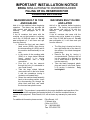
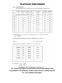
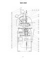
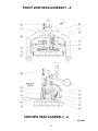
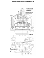
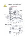
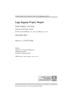
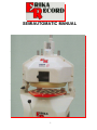
SEMIAUTOMATIC MANUAL
1
IMPORTANT INSTALLATION NOTICE
ERIKA SEMI-AUTIOMATIC DIVIDER/ROUNDER
FILLING OF OIL RESERVOIR FOR
ROUNDING MECANISIM
MACHINES BUILT IN 1999
AND EARLIER
MACHINES BUILT IN 2000
AND LATER
Add oil to the machine before beginning
operation. The factory has provided the
right amount and type of oil with the
machine.
(see paragraph #4 in the
manual).
If the oil container that came with the
machine can not be located or is missing;
use 2 Qts. Of SAE #40 motor oil. Do not
use multigrade oil, it will foam and spill
from the reservoir.
• Remove the front and rear plastic
head covers (S009), then remove
the disconnecting pin (S036) and tilt
the machine head assembly to one
side.
• In the center of the rounding table
(S042) is a large slotted flathead
screw, remove it by turning
counterclockwise with a large
screwdriver.
• Pour the oil into the reservoir
through the hole (it is advisable to
use a small funnel).
• Take the large slotted flathead
screw and insert in the hole, fasten
it with the screwdriver turning it
clockwise until seated firmly.
• Return the machine head assembly
back to the working position. Insert
the disconnecting pin through the
pillow block and arch; and install
the front and rear plastic covers.
Add oil to the machine before beginning
operation. The factory has provided the
right amount and type of oil with the
machine.
(see paragraph #4 in the
manual).
If the oil container that came with the
machine can not be located or is missing;
use 2 Qts. Of SAE #40 motor oil. Do not
use multigrade oil, it will foam and spill
from the reservoir.
•
•
•
The filler plug is located on the top
rear right hand side of the base of
the machine, it is a black hexagonal
plastic plug.
Remove the plug by turning it
counterclockwise. Then pour the oil
into the opening (it is advisable to
use a small funnel to pour the oil
into the reservoir).
Take the black hexagonal plastic
plug and insert it in the hole, fasten
it by turning it clockwise. Only
hand tighten.
DISCLAIMER: The purchaser is responsible for the proper installation and operation of the
machine. Should this equipment be operated without oil, it shall be considered abuse or
misuse of the equipment. Erika Record, LLC will not honor any warranty for parts and/or
labor.
For additional information please contact:
Erika Record, LLC
37 Atlantic Way
Clifton, NJ 07012
Tel: 1-800-682-8203
Fax: 973-664-1752
2
Technical Information
To ensure proper use and to avoid accidents it is
imperative to read the entire instruction manual prior
to use of this machine.
3
• Remove the base cover that has a
yellow label indicating the storage of
an oil container in the base.
• Remove the oil container.
• Remove the four nuts that hold the
machine to the wooden pallet.
• Now drive the bolts through the
wood with a hammer.
• Gently remove the strings and the
wood piece that holds the rounding
plates in place.
• Get a forklift truck, or 2 or 3
helpers, to remove the machine from
the pallet.
• NEVER attempt to remove the
machine from the pallet on your own.
• CAUTION: Remove the pressure
lever (S030), which is attached to the
rounding lever (S050).
• The machine has to be placed on a
floor that is level, with sufficient space
around, for a safe and efficient
operation.
• The machine has to be bolted to
the floor with appropriate anchors, and
the gap between the floor and the base
has to be sealed, to prevent water,
flour, etc. from entering the base. We
recommend the use of silicone
caulking. Unless the machine has been
fitted with a set of wheels provided by
the factory.
• NEVER install “off the shelf type”
casters under the machine.
• This is dangerous because the unit
is top heavy, and the operator could
easily topple the unit over while pulling
the handle.
1. CAUTION
Please read and familiarize
yourself with the safety instructions
contained in this manual, and the
labels attached to the machine. This
shall be done before you operate,
clean or service the machine.
It is the purchaser’s responsibility
to make sure, that the operators of this
machine are aware of the contents of
this manual.
It is also the responsibility of the
purchaser to translate this manual in
any other language, for non-English
speaking operators.
2. OWNER’S RESPONSIBILITIES
• The owner of this machine, and the
supervisory personnel shall read and
follow the instructions contained in this
manual.
• Make sure that this manual is
readily available for the operators of
this machine.
• All the operators shall be properly
trained and be aware of all the safety
features of the machine, and they shall
be properly supervised while operating
this machine.
• Make sure that the machine is
installed conforming to all applicable
codes and regulations (local, state
and federal) including OSHA
regulations and electrical codes.
• All the warning labels and decals
have to be visible at all times.
• The instruction manual for the
operation of this machine shall be kept
in a safe place next to the machine.
4. FILL OIL RESERVOIR - Please refer
3. INSTALLATION
• After removing the sides of the
wooden crate, the machine has to be
removed from the wooden pallet, to
which it is bolted with four bolts for safe
transportation.
• Cut open the plastic sleeve in
which the machine is packaged to
avoid moisture problems in transit.
to page 2 of this manual for detailed
instructions for first use.
• Add oil to the machine before
putting it in operation. The factory has
provided the right amount and type of
oil with the machine (see paragraph #
3).
• The filler plug is located at the rear
right hand side of the machine; it is a
black hexagonal plastic plug.
4
• Remove by turning
counterclockwise; it is advisable to use
a small funnel to pour the oil in the
reservoir.
• If the oil is missing, use 2 qts. of
SAE 40 weight motor oil.
• Once the oil has been poured in the
reservoir, the machine is lubricated for
life; there is no need to replace or
change the oil.
(S036) and tilt the machine head to
one side.
• Clean the grease from the machine
head and rounding table using paper
towels or a soft cloth.
• Bring the machine head back to its
original position, install the
disconnecting pin, dough ring and
plastic head covers.
• Even though you now have cleaned
the product zone, use the first two or
three batches of dough to do the final
cleaning (see paragraph # 9).
5. ELECTRICAL
Unless stated otherwise, the machine
has a 190/230 volt, 3 phase, 60 cycle
electric motor. Make sure the machine
is connected to the correct voltage.
This information is printed on the
machine identification label (located on
the base, next to the power cord
connector). Only a qualified electrician
is to connect the machine to the power
source.
8. CHOOSING THE SETTINGS
• The adjustment screw (S032) sets
the height of the rounding chamber of
each dough piece. If the adjustment
screw is in the “up” position (turn
counterclockwise), it will accommodate
a large piece of dough, whereas in its
“down” position (low numbers) it will
accommodate a small weight.
• For example: Setting #2 may
handle approximately 2 to 3 pounds of
dough, whereas setting #7 may handle
approximately 5 pounds of dough on a
model 9/20; 7.5 pounds on a model
10/25; and up to 9 pounds on a model
11/30. If the operator does not choose
the right setting, he will not get a wellrounded product.
• The dough pieces will be flat rather
than round indicating that there is too
much molding space and, therefore the
adjustment screw has to be turned
clockwise for the next batch.
6. INITIAL START UP
• The motor is protected by an
overload device, part of the manual
starter; when running the machine for
the first time, make sure the rounding
table (S042) rotates in the right
direction (check arrow on the front of
the unit), the rounding table has to turn
counterclockwise. If this is not the
case, the machine will not function
properly; have an electrician reverse
the rotation of the electric motor.
WARNING: The rounding table (S042)
is secured to the base of the machine
DO NOT TRY TO LIFT OR REMOVE
IT. Serious damage to the rounding
mechanism will result. Only qualified
service people are to remove the
rounding table.
• On the other hand, if the rounded
pieces of dough show a nipple in the
top center, it would indicate that the
rounding chamber is too low and, the
adjustment screw has to be turned
counterclockwise to correct this
problem.
• It is best to retry after giving one or
two full turns to the adjustment screw.
Once the setting is correct, note it on a
piece of paper for future reference.
7. CLEANING – FIRST START-UP
• The machine is shipped with a light
protective grease in the head assembly
to avoid oxidation during transit.
• Remove the front and rear plastic
covers (S009) and the dough ring
(S007), (please read paragraph # 14)
then remove the disconnecting pin
5
• Now push the pressure lever
(S030) all the way to its end position,
to cut the dough into pieces.
• Still holding the pressure lever
(S030) down, move the rounding lever
(S050) progressively to the left, this
will start the rounding process.
• Keep the rounding lever engaged
from three to five seconds, depending
of the type of dough.
• Release the rounding lever to
its
position, raise the pressure arm to the
top “up” position, remove the plastic
rounding plate from the machine.
• Check the quality of the finished
pieces; and if necessary, make
adjustments as indicated in paragraph
# 9.
• Please also remember that
settings will differ from one type of
dough to another.
9. OPERATION OF THE MACHINE
• The first batch of dough is to be
used to do the final cleaning of the
machine. Keep using the same dough
several times, before going to the next
piece. Continue this operation until you
no longer see any discoloration of the
dough, and the product zone in the
machine is completely clean.
• A piece of the dough first has to be
weighed within the total weight
parameters of the machine. See page
3 of this manual for the weight ranges.
(They are approximate since they
depend on the dough type and
handling).
• Place the scaled piece of dough
onto the red plastic rounding plate
(S066), with the moist side pressing
against the plate.
• Spread the dough evenly to the
outmost circle of rings, so that it covers
approximately the inner half of the
outer circles.
• Only apply some dusting flour on
top of the dough.
• Never use dusting flour between
the dough and the rounding plate.
• Insert the plate with the dough in
the machine, and make sure that the
plate is properly seated on its locating
peg.
• Make sure that there are no scraps
on the bottom of the plastic plate or on
top of the rounding table, since this will
damage the knives or the red plastic
rounding plate.
• Once the red rounding plate has
been properly placed, pull down the
pressure lever (S030) and compress
the dough evenly by pushing down on
the lever as much as you can.
• (It is easier to push down in short
strokes several times).
• Release the pressure lever
somewhat and press the cutting lever
(S010) to the right.
10. DIVIDING ONLY
• Insert one red rounding plate
(S066) face down as a base on the
rounding table (S042).
• Prepare dough on another plate as
described in paragraph # 9 (remembermoist side down).
• Dust with flour only the top side of
the dough.
• Place the plate with the dough, on
top of the rounding plate inserted face
down in the machine.
• Without running the motor, press
and divide the dough as indicated in
paragraph # 9.
11. MAINTENANCE AND REPAIRS
• The machine has to be inspected
on a regular basis, and maintenance
performed as needed.
• Any repairs are to be done by
authorized service personnel only,
and only original spare parts should
be used.
• The use of non-approved spare
parts may void the manufacturers
warranty.
6
• The adjusting screw (S037)
determines how far the knives will
travel.
• This is accomplished by limiting
the travel of the pressure lever (S030).
• The clearance between the knives
in their “down” position and the plastic
rounding plate should be the thickness
of a sheet of paper.
• If the knives touch the rounding
plate, first make sure that no dirt or old
dough sits between the plastic plate
and the metal rounding “table”.
• If it is clean, remove the dough
entrapment ring (see paragraph # 15).
• Place a sheet of paper on top of the
plate (parchment paper or newspaper).
• (a)Bring down the head of the
machine, and release the knives.
• (b)Pull gently on the paper, you
should be able to pull it out without
tearing.
• (c)If you tear the paper, or are
unable to pull it out, you have to raise
the blades, to do this:
• (d)Release the locknut on the
adjustment screw (S037), that stops
the handle on the way down.
• Turn the screw counterclockwise
one full turn, then repeat steps (a-b-cd) until the paper slides out.
• Fasten the locknut on the
adjustment screw (S037) clockwise.
• Install dough entrapment ring.
12. ADJUSTMENT OF THE V BELTS
• In time, the V belts located in the
base of the machine will wear and
stretch.
• To adjust them, loosen the motor
bolts, move the motor on its railing until
the belts are tight, (see paragraph #
13) tighten the bolts again.
13. REPLACEMENT OF THE V BELTS.
• Disconnect electrical power from
the machine.
Remove the left side cover from the
machine base.
• Release spring (S054) completely,
and disconnect from the frame.
• Tap out beveled pin (S061) from
the bottom up, and remove.
• Pull and turn lever (S050), until
assembly S050/58 is free.
• Loosen the 4 bolts that hold the
motor (S071) to the motor mounts
(S092), and slide the motor until the 3
V belts (S070) are loose.
• Remove the old V belts one at a
time, and replace with new ones.
• Slide the motor until the 3 new V
belts are tight; when pushing against
the new belts with your finger you
should get a ¼” deflection, if you get
less, damage to the motor bearings will
be the result, if you have too much
play, the belts will slip.
• Re-tighten the 4 bolts that hold the
motor to the machine frame.
• Push and turn lever S050 and
insert assembly S058/50.
• Insert beveled pin S061 from the
top into the assembly S058/50, and
tap gently until fully seated, do not
force pin or rivet it, just tap gently.
• Insert spring S054 and tighten until
the lever S050 moves freely to it’s
resting position.
• Install the left side cover on the
base of the machine.
• Re-connect the electrical power.
•
12.
15. REMOVING THE DOUGH
ENTRAPMENT RING (S007)
• Pull down the pressing lever
(S030), keep it down by holding it
under your armpit, and now grab the
dough entrapment ring with hands, one
in the front and one in the back.
• Turn the ring clockwise until the
slots on the top of the ring line up with
the holding brackets (S081); now
release the pressing lever to the “up”
position.
• The ring can now be removed from
the machine.
ADJUSTMENT OF THE KNIVES
7
• Important: The dough entrapment
ring must be cleaned daily after use.
Apply margarine or butter as a sanitary
lubricant.
• Place the clean ring back on the
rounding plate with the slots on the top
of the ring lining up with the holding
brackets.
• Slowly pull down the pressing lever
until the holding brackets drop through
the slots in the ring.
• Turn the ring counterclockwise,
until the end stop seats against the
holding bracket on the right side of the
machine.
• Caution: NEVER use metal
scrappers or sharp objects to clean the
ring. If the ring is Teflon coated, it
should only be cleaned with a cloth or
paper towels.
dough should be softened with any
household window cleaner (plastic
spray bottle), and wiped clean with a
dry cloth or paper towels.
• Never spray water on the machine
with a hose or pressure washer,
because the frame and the various
moving parts are made of cast iron;
also water will accumulate in the inside
of the machine, since it is not sealed.
• Important: The knives should be
cleaned daily, (see paragraph # 7).
• Dough accumulation, and/or
insufficient cleaning will result in
broken springs due to excessive
friction between parts.
17. PROCEDURE TO DETERMINE
MODEL OF THE DIVIDER / ROUNDER.
• Measure the distance (A) center to
center of the disconnecting pins (S036)
as indicated in drawing # 1.
• If A = 19 ½” the machine is a
model 2/36.
• If A = 21 ½” the machine is a
model 5/18 or larger.
• Measure the inside diameter of the
dough entrapment ring (B), as
indicated in drawing # 2.
• If B = 14 3/8” the machine is a
model E2/36 or 9.
• If B = 14 15/16” The machine is a
model 10.
• If B = 15 15/16” The machine is a
model 11 or larger.
• Finally count the number of
divisions as in drawing # 3.
16. CLEANING OF THE MACHINE
• The rounding table (S042) is made
of steel, and should be cleaned with a
dry cloth only. Do not use water.
• The rounding plates (S066), which
are made out of plastic, should be
cleaned with a soft nylon brush and
warm water only!
• Never try to clean them in a pan
washer, or dry them in an oven, this
will cause the plates to warp, and
later damage the knives in the
rounding head.
• The cutting knives, installed in the
piston/knife assembly (S025), should
be cleaned daily with a soft dry cloth or
soft plastic brush. To do this, first
remove the dough entrapment ring
(see paragraph # 15).
• The entire head assembly is
Anodized, never use metal scrappers,
steel wool or sharp objects of any kind,
to clean or remove dough or flour that
may accumulate. The use of
compressed air is acceptable.
• The base of the machine, and the
plastic covers (S009) of the
piston/knife assembly, should be
cleaned daily with a dry cloth or a soft
plastic brush; heavy stains or caked on
8
DRAWING # 3
DRAWING # 1
18. ORDERING REPLACEMENT
PARTS.
• Have the serial number and
machine model available when
ordering parts. Compare the damaged
part with the diagram and parts list
supplied in this manual to determine
the item number. This will expedite the
processing of the order and avoid the
shipping of wrong parts.
• Call your local service agent/dealer,
or ERIKA RECORD LLC at 1-800-6828203 (outside the USA 1-973-6148500) Fax 1-973-614-8503.
DRAWING # 2
•
You may also contact us by E-mail:
[email protected]
[email protected]
9
Removable Head – Semiautomatic “RH”
Divider/Rounder Machines
REMOVAL OF THE PISTON/KNIFE HEAD ASSEMBLY.
1. Remove front and back covers (S009).
2. Remove dough entrapment ring (S007).
3. Insert 2 rounding plates (S066) on top of the pressure plate (S042).
4. Lower the pressure handle (S030) all the way.
5. Loosen the 2 hexagonal bolts (S023) completely – use a 22-mm.
wrench.
6. Insert an Allen wrench (6mm.) along the groove on top of the head
(picture #1); lock the wrench in the screw head (NOT VISIBLE see
picture #2 A and picture #2 B), turn counterclockwise 3 or 4 turns.
7. Raise the pressure handle S030) all the way to the top position.
8. Remove the piston/knife assembly (S025) from the machine.
9. Wash and clean the piston/knife assembly thoroughly in a pan
washer or sink.
INSTALLATION OF THE PISTON/KNIFE ASSEMBLY.
1. Insert 1 rounding plate (S066) and the white installation plate, which
is marked with a single circle and numbered marks, on top of the
pressure plate (S042). (The white installation plate has to be on top).
2. Place the clean piston/knife assembly on top of the rounding plates.
3. The markings on the piston/knife head assembly must line up with
the corresponding number on the white plate : 0=0; 1=1; 2=2; 3=3.
4. Carefully lower the pressure handle (S030) all the way; making sure
all the marks on the parts line-up correctly. Hold the pressure arm
under your armpit.
5. Tighten the 2 hexagonal bolts (S023) firmly – use a 22 mm. Wrench.
6. Press down firmly on the pressure handle (S030) so as to seat the
knives cross-piece (S082) in the gear bar (S029).
7. Insert the Allen wrench (6mm.) along the groove on the top of the
piston/knife assembly (picture #3). Lock in the screw head; turn
clockwise until it is tight (picture #4).
8. Raise the handle (S030) all the way to the top; now lower and raise
the head assembly 2 or 3 times, releasing the knives each time by
pressing the lever (S010) when in the low position. (Check Allen
screw (Step #6); make sure it is tight.
9. CARE MUST BE TAKEN THAT THE GEAR BAR (S029) IS FULLY
SEATED ON THE CROSS-PIECE (S082), OTHERWISE
SCRATCHES OR CUTS WILL BE MADE ON THE SURFACE OF
THE ROUNDING PLATES.
10. Remove the 2 plates inserted in step # 1.
11. Install the dough entrapment ring (S007) on the piston/knife head
assembly.
12. Install the front and back safety covers (S009).
10
Insert SH Page
11
Spare Part List
S – 001
Stop
S – 002
Latch
S – 003
Latch Pivot
S – 004
Fork Casting w/ Curve
S – 005
Ring Guide
S – 006
Pull Spring
S – 007
Dough Ring
S – 008
Arch for S – 004
S – 009
Cover Front/Rear
S – 010
Cutting Arm
S – 011
Bearing Cover
S – 012
Pin
S – 013
Counter Weight
S – 014
Latch Bow
S – 015
Straight Pin
S – 016
Adjusting Screw
S – 017
Pin
S – 018
Pin
S – 019
Connection Bar
S – 020
Pin
S – 021
Snap Ring
S – 022
Pin
S – 024
Flange
S – 025 / 074 / 082
Piston w/ knife-head ass.
S – 026
Screw
S – 027
Arch
S – 028
Gear Segment
S – 029
Gear Bar
S – 030
Pressure Arm
S – 031
Segment Bolt
S – 032
Adjusting Screw
S – 033
Pull Spring
S – 034
Screw
S – 035
Pillow Block
S – 036
Disconnecting Pin
S – 037
Adjusting Screw
S – 038
Roller Bearing
S – 039
Angle Lift
S – 040
Bushing
S – 040A Drive Assy.
S – 041
Bearing Housing
S – 042
Pressure Plate
S – 043
Ball Bearing
S – 045
V-Belt Pulley
S – 046
V-Belt Pulley Motor
S – 047
Collar
S – 048
Slide Bar
S – 049
Bushing
S – 050
Molding Lever Assy.
S – 051
Flange Bearing
S – 052
Knob
S – 054
Pull Spring
S – 055
Self Aligning Bearing
12
S – 056
S – 057
S – 059
S – 060
S – 062
S – 063
S – 066
S – 067
S – 068
S – 069
S – 070
S – 071
S – 073
S – 075
S – 076
S – 077
S – 078
S – 079
S – 080
S – 081
S – 082
S – 083
S – 084
S – 086
S – 087
S – 088
S – 089
S – 090
S – 091
S – 092
S – 096
S – 099
S – 101
S – 102
S – 104
S – 105
Bearing Housing
connecting Arm
Pin
Connecting Rod
Oil Drain Plug
Oil Filler Cap
Moulding Plate
Pin
Pin
Knob
V-Belt
Motor
Sleeve
Spring Guide
End Stop
Shoulder Bolt
Pull Spring
Spring Stud
Guide
Hook-Screw
Cross-Piece
Guide Pin
Vertical Guide Casting
Housing
Spring Bolt
Lock Nut
Spring Support
Retaining Ring
Stop Pin
Motor Bracket
Pin Pivot Arm
Arrowhead Pin
Circuit Breaker
Box F. Circuit Breaker
Pilot Light
Wheel Assy.
Q99-113
Q0030Q1
Q0015Q1
Q0010Q1
Q0030Q2
Q0015Q2
Q0010Q2
Q0036Q3
Q0018Q3
Q0012Q3
Q0009Q3
Q0006Q3
Q0003Q3
Roller (transport)
Knife 30 pcs. f. Q1
Knife 15 pcs. f. Q1
Knife 10 pcs. f. Q1
Knife 30 pcs. f. Q2
Knife 15 pcs. f. Q2
Knife 10 pcs. f. Q2
Knife 36 pcs. f. Q3
Knife 18 pcs. f Q3
Knife 12 pcs. f. Q3
Knife 9 pcs. f. Q3
Knife 6 pcs. f. Q3
Knife 3 pcs. f. Q3
Specifications for different types of Semiautomatic machines
S – 005A
S – 005B
S – 007A
S – 007B
S – 007C
S – 007D
S – 009A
S – 009B
S – 009C
S – 009D
S – 009E
S – 009F
S – 016A
S – 016B
S – 024A
S – 024B
S – 025A
S – 025B
S – 025C
S – 025D
S – 025E
S – 025F
S – 025G
S – 025I
S – 027A
S – 027B
S – 027C
S – 027D
S – 027E
S – 029A
S – 029B
S – 029C
S – 032A
S – 032B
S – 035A
S – 042A
S – 066/1
S – 066/2
S – 066/3
S – 066/4
S – 066/5
S – 066/6
S – 066/7
S – 066/8
S – 066/9
S – 066/10
S – 066/11
S – 071A
S – 081A
S – 081B
S – 082A
S – 082B
S – 082C
Ring Guide Type 10/25 + 11/30
Ring Guide Type 2/36 + 9/20
Dough Ring Type 11/30
Dough Ring Type 5/18
Dough Ring Type 2/36 + 9/20
Dough Ring Type 10/25
Cover Front, round Type 9/20 + 10/25 + 11/30
Cover Front, Square Type 9/20 + 10/25 + 11/30
Cover Front, Type 2/36
Cover Rear, Round Type 9/20 +10/25 + 11/30
Cover Rear, Type 2/36
Cover Rear, Square Type 9/20 + 10/25 + 11/30
Adjusting Screw, Type 9/20 + 2/36
Adjusting Screw, Type 10/25 + 11/30
Flange Type, 10/25 + 11/30
Flange Type, 2/36 + 9/20
Piston w/ Knifehead Assy., Type 11/30
Piston w/ Knifehead Assy., Type 10/25
Piston w/ Knifehead Assy., Type 9/20 + 2/36
Piston w/ Knifehead Assy., Type 7/70
Piston w/ Knifehead Assy., Type 6/150
Piston w/ Knifehead Assy, Type 5/18
Piston w/ Knifehead Assy, Type 4/40
Piston w/ Knifehead Assy, Type 11/30
Arch Round, Type 10/25 + 11/30
Arch Round, Type 9/20
Arch, Type 2/36
Arch, Type 10/25 + 11/30
Arch, Type 9/20
Gear Bar, Type 4/40 + 6/150
Gear Bar, Type 10/25 + 11/30
Gear Bar, Type 2/36 + 9/20
Adjusting Screw, Type 10/25 + 11/30
Adjusting Screw, Type 2/36 + 9/20
Pillow Block, Type 9/20 + 10/25 + 11/30 + 2/36
Pressure Plate, Type 9/20 + 10/25 + 11/30 + 2/36
Moulding Plate, Type 10/25 – 36 Parts #336
Moulding Plate, Type 11/30 – 36 Parts #46
Moulding Plate, Type 2/36 – 36 Parts #26
Moulding Plate, Type 4/40 – 30 Parts #45
Moulding Plate, Type 5/18 – 50 Parts #50
Moulding Plate, Type 6/150 – 15 Parts #415
Moulding Plate, Type 7/70 – 20 Parts #420
Moulding Plate, Type 9/20 – 36 Parts #326
Moulding Plate, Type 3/30 – 30 Parts #35
Moulding Plate, Type 2/25 – 30 Parts #25
Moulding Plare, Type 8/250 – 7 Parts #47
Single Phase Motor 0,55 kw
Hook-Screw, Type 11/30
Hook-Screw, Type 9/20 + 10/25 + 2/36
Cross-Piece, Type 11/30
Cross-Piece, Type 10/25
Cross-Piece, Type 9/20+ 2/36
Please look at your Machine Type Label before ordering!
13
FRONT VIEW
14
SIDE VIEW
15
FRONT VIEW HEAD ASSEMBLY - A
SIDEVIEW HEAD ASSEMBLY - A
Front View
16
FRONT VIEW HEAD ASSEMBLY - B
Top View
Top View
17
SQUARE HEAD DRAWING
TOP VIEW HEAD ASSEMBLY
Top View
18
FRONT VIEW HEAD ASSEMBLY - A
19
Trouble Shooting
ERIKA Semiautomatic Bun Divider Rounders
1. Dough Pieces Do Not Round
• Rounding chamber is too big
(Adjust screw #32 clockwise)
• Knives do not cut through dough
(Adjust screw #35 clockwise)
• Wrong rounding plate
(Check the number on your rounding plate
to make sure it is the right one for the machine)
2. Rounded Dough Pieces Have Nipples
• Rounding chamber is too small
(Adjust screw #32 counterclockwise)
(Check spring #33 to make sure that it
pulls back the dividing head to molding
space stop at bottom of part #32)
3. Machine Does Not Run
• Check electrical power supply
• Reset motor starter by pressing “stop and start” button
• Check V-belt
For any additional information, please contact the closest service agency
or call 1-800-682-8203
20