1
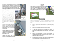
HT-Salad Harvester User Manual REID LINE EAST, RD 5 FEILDING 4775, New Zealand Phone (06)323 2509 Fax (06)323 2709 Email [email protected] 02/09 © Harvester Concepts Ltd 2005 16 Conditions of Sale and Guarantee Your HARVESTER CONCEPTS LTD product is guaranteed to be free from defects in materials and/or workmanship under normal use and service for a period of 6 months from date of initial purchase. HARVESTER CONCEPTS LTD’S liability and obligation is limited to problems which HARVESTER CONCEPTS LTD acknowledges to be defective under the guarantee conditions either to - the free replacement or repair (where practicable) at the HARVESTER CONCEPTS LTD premises of any parts returned within the guarantee period - or shipment of replacement parts to the customer, as mutually agreed to. Supply of non standard parts or services from other than HARVESTER CONCEPTS LTD are not covered under the guarantee conditions unless prearranged, in writing, with HARVESTER CONCEPTS LTD Shipment of product to HARVESTER CONCEPTS LTD is the consumers responsibility and cost Guarantee conditions are void for any of the following reasons:Abnormal use of the product Accident damage or vandalism Modifications or unauthorised repairs to the product or its components Where component "seconds" have been supplied Normal wear and tear HARVESTER CONCEPTS LTD cannot be held liable for any damage caused to people or other property during use of the product or as a result of any defect or malfunction of product or components supplied by HARVESTER CONCEPTS LTD. Use of the product is solely the users responsibility. Other losses such as delays in work, incorrect or misleading information, omissions and errors, HARVESTER CONCEPTS LTD is not liable for. This guarantee is expressed in lieu of all other guarantees expressed or implied and all other obligations and liabilities on HARVESTER CONCEPTS LTD's part and specifically excluding consequential damage. HARVESTER CONCEPTS 2 15 LTD makes no guarantee of merchantability or fitness for purpose and is not responsible to any purchaser of its products for any undertaking, representation or guarantee, except those stated in these terms, made by any person, dealer or body corporate selling or dealing with its products in any manner whatsoever. Index Page 2 3 4 5 6 9 10 12 13 14 Conditions of sale and Guarantee Specifications Introduction / safety notes Your HT-Salad consists of Options / Assembly Travel / Dismantling Start Up Fault Finding / Maintenance Freighting / Notes Spare Parts List Specifications Cutting Height - with roller - Ground level up to 125mm in 9 steps - with optional 200 dia wheels 115 to 175mm in 5 steps Cutting Width - 1200mm Dimensions: Ready to use - approx 1500 wide / 2180 long / 800 high Weight, dry - 49 Kg For Freighting Purposes - On pallet Approx Weight - 71 Kg Dimensions - 1660 x 1440 x 660 high 14 3 ted. HT-Salad Harvester Introduction Congratulations on the purchase of your Harvester Concepts Ltd HT— Salad Harvester. This machine is of high quality and will reward you with reduced effort and greater efficiency in your harvesting. With the travel wheels fitted, the harvester can be tilted forward until the cutter bar is adjacent to the ground. This gives good access for washing down, draining off excess water afterwards, also gives access to the roller for cleaning The cutter bar should be lubricated with either the Ochiai grease supplied or a food compatible lubricant / rust inhibitor before storing and at regular operating intervals (every time the engine is refuelled). Lubricate the power head in accordance with the manufacturers recommendations (every 20 hours). There is a grease nipple on the gearbox. The wheels and handle bars can be removed for storage or freighting. The HT-Salad harvester can be used for harvesting a big range of crops from either flat or raised beds Learning to operate your HT—Salad won't take long. You will soon find it to be an invaluable tool. Important Safety Note Freighting Read and understand all the instructions before using the HT-Salad. The HT–Salad should only be used for the purposes for which it was designed. Use it for no other purpose (e.g. it is not a grader blade or battering ram!). We have manufactured the HT-Salad using quality materials and manufacturing techniques however if faults do occur please have them corrected before you use it. Please read the Power Head instruction book before use. Pay particular attention to running in and safety notes. Please read this instruction book before use and retain it for future reference. It requires only one person to operate the HT-Salad - keep all others away! Immediately after turning the power head off, fit the cutter bar cover. It should be removed last, before restarting the power head. 4 Freighting on the back of a utility vehicle is preferred. The HT-Cress is very light and if transporting on a trailer it is not heavy enough by itself to make the trailer springs work i.e. it will get badly shaken about. On rough road / tracks this could cause structural damage. One solution is to put a extra weight on the trailer as well as the harvester so the springs actually work! Notes 13 Your HT-Salad Consists of: Fault Finding Engine will not start - Ensure stop switch on power head is turned on. - Refer to manufacturers handbook 1. 2. 3. 4. 5. 6. Power Head - Ochiai V8 new Z1210 (S/N Power Head instruction book and spanners Handle Bar Frame, large and small, c/w lynch pins 2 Large travel wheels and small rear wheel Mainframe complete with chute, cover and deflector Manual operating handle bars Rear Mounted handle bar frame Other power head problems - Refer to manufacturers handbook Chute clogs - Engine not operating fast enough—rev up. ) Raise/ lower lever Travel Wheel (Stowed) Deflector Cover - Crop too long. Cut in 2 stages - crop wet / too heavy. If possible let dry out. Harvest at a slower walking speed. If you require further assistance or spare parts, please call Harvester Concepts Ltd. Spare bin Frame Maintenance Wash down the HT-Salad harvester after use. Only wash enough to remove dirt. Over washing could induce corrosion. Sealed bearings are utilised but water under pressure could penetrate them. The cover can be removed by unlatching the two rubber retainers. Inside the cover and chute should be washed clean, dried and refit- 12 Power Head Fingers 5 in accordance with the manufacturers handbook. Note: Especially during running in , vary the throttle setting - don’t rev continuously. Options Wheels, cutter height adjust. 200mm dia. Crop lifting fingers 6. Let the engine warm up for a minute. Use the throttle control (lower lever) to rev the engine up. The cutter bar is engaged using the upper lever. Especially in heavy, wet crops full throttle should be used to blow the cuttings into the collection bins. It is a good idea to stop the cutting blades and throttle the engine back when not harvesting or changing the collection bins. 7. The engine must be stopped and the cutter bar cover fitted before any adjustments are done. CAUTION: Do not approach the front of the machine with the engine running. Always switch it off and fit the cutter bar cover. There is a red stop button on top of the engine also an ignition switch nearer the Left on the power head frame. Assembly Unpack the harvester ensuring you receive all the parts and that they have not been damaged in transit. Layout the components on the ground in their rough position Fit the small rear wheel into its holder until nib spring latches in retaining hole. The HT-Salad can be either pushed or pulled (best in rough ground or if you need to monitor the crop being cut). The large or small handlebars can be used. If you wish to walk in the wheel track while harvesting, the small handle bars should be used, mounted facing outwards. Fit the handle bars accordingly and secure with the Lynch pins. . Fitting rear handlebars Note The HT-Salad should be used in such a way as cuttings do not gather around the fan casing or it’s plastic mesh. Failure to do this could result in ingestion of cuttings, clogging of the cooling flow to the engine and engine seizure! If cuttings gather at the plastic mesh, stop the power head and clear the cuttings away immediately! If the handlebars have been fitted in front of the machine, the engine controls at the cable ends, can be mounted on the small tube protruding from the handle bars. If rear mounted handlebars only are used, the engine controls can be mounted on the raise / lower lever. 6 11 Start Up 1. Fit collection bins and spares if required. Two collection bins can be fitted to the machine. Tilt the deflector forward and lower the bins onto the holding rails. Tilt the deflector rearwards. Spare bins sit on the chute cover between the cross members 2. Remove travel wheels and fit in stowed position 3. If the plant rows are around 1200mm wide it may be necessary to fit the crop lifters (fingers). Rotate the deflector forward. This allows access for fitting the vege bins. Two large bins should be fitted. Rotate the deflector rearwards covering the bins. More empty bins can be stored on top of the chute cover, between the retainers. If you are at the harvesting site the travel wheels can be stowed in their brackets as shown Crop Lifters: Engine controls Cut height adjustment The crop lifters are particularly effective for gathering in the crop where it extends past the width of the harvester. These are easily fitted using the lynch pins supplied. Note that there is a left hand and right hand finger RH Cover latch 4. 5. Latch bolt Roller Adjust the cutting height. Take the machine weight on the adjusting lever and pull the latch bolt outwards (twisting it 90º will lock it out), move the lever to give the desired cutting height at the blade. Relatch the lock bolt in the closest hole. Remove the cutter bar cover. It may be stored over the chute cover cross member. The power head should be refuelled and started 10 LH Lynch Pin Crop Lifter Roller / wheels: The HT-salad is standard with the roller fitted. However for certain crops or higher cutting the wheel option has the advantage of not flatten7 RH Travel ing down the remaining plant. To gain access for changing between the roller and wheels, it is perhaps easiest to stand the machine on end, as shown, and lean it against a wall or similar. Note: Take care not to damage the front of the power head. If possible place a mat under it and always ensure the cutter blade cover is fitted. If the roller is fitted, remove the wiper bar first, then unscrew the grub screw in each end of roller mount as shown, using a 3mm allen key. Screw in the M6 extraction tool (supplied) and pull the pin out to almost disengage the roller. Do the same at the other end of roller until the roller can be removed. The pins and grub screws can either be totally removed or refitted so they don’t get lost. There is a flat on each pin; ensure it lines up with the grub screw. To fit the wheel assembly; Ensure the scrappers on the wheels are at the rear (top) side and offer the wheel frame up to the mounting frame. Secure with the 2 through bolts. Note that with the wheels fitted the HT -Salad has a different height cutting range and all the height adjusting holes cannot be used. When you need to travel between harvesting sites fit the travel wheels. With one hand lift the main frame forward of the mounting point. With the other hand position the boss on the wheel axle into the slotted hole and lower harvester so wheel takes it’s weight. Repeat for other side. Pin extraction tool Dismantling Grub Screw This is in reverse of assembly. The Power head should only be removed if it is to be used manually, without the harvester frame. Remove as follows: Remove engine controls from handle bars by unscrewing wing screw. Remove 2 vertical bolts at left hand power head mount. At right hand mount, There are 2 horizontal bolts holding the Power head mounting frame to the main frame - remove these bolts Remove power head, loosen 2 cam lock sleeves and pull the mounting frame out of the cam locks. Fit engine controls to left hand forward tube on power head. Fit manual handles. Cam lock fittings may need rotating. Release lever at forward end, reposition fittings and relock lever. Changing from wheels back to the roller is a reverse of the above procedure 8 9