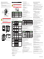
1
Operation
Guide
UP55A
Program Controller
Operation Guide for Single-loop Control
IM 05P02C41-11EN
Installation and Wiring
2nd Edition : Jan. 2011
This operation guide describes installation, wiring, and other tasks required to make the
controller ready for operation.
Contents
1.
2.
3.
4.
5.
6.
Safety Precautions
Model and Suffix Codes
How to Install
Hardware Specifications
How to Connect Wires
Terminal Wiring Diagrams
Introduction
Thank you for purchasing the UP55A Program Controller.
This operation guide describes the basic operations related to the single-loop control
function of the UP55A. The guide should be provided to the end user of this product.
Be sure to read this operation guide before using the product in order to ensure
correct operation.
For details of each function, refer to the electronic manual contained in the provided
CD-ROM. Before using the product, refer to the table of Model and Suffix Codes to
make sure that the delivered product is consistent with the model and suffix codes
you ordered. Also make sure that the following items are included in the package.
• Program Controller (the model you ordered)...........................................x1
• Set of Brackets.........................................................................................x1
• Unit Label (L4502VZ)...............................................................................x1
• Tag Label (L4502VE)...............................................................................x1
(Only when ordered.)
• Terminal Cover (L4502XP)......................................................................x1
• Operation Guide for Single-loop Control (this document)........................x7 (A3 size)
(Installation and Wiring, Initial Settings, Programming, Operations, and Parameters)
• User’s Manual (CD-ROM)........................................................................x1
Target Readers
l
This guide is intended for the following personnel;
• Engineers responsible for installation, wiring, and maintenance of the equipment.
• Personnel responsible for normal daily operation of the equipment.
1. Safety Precautions
The following symbol is used on the instrument. It indicates the possibility of injury
to the user or damage to the instrument, and signifies that the user must refer to
the user’s manual for special instructions. The same symbol is used in the user’s
manual on pages that the user needs to refer to, together with the term “WARNING”
or “CAUTION.”
WARNING
CAUTION
2. Model and Suffix Codes
n Safety, Protection, and Modification of the Product
(1) In order to protect the system controlled by this product and the product itself,
and to ensure safe operation, observe the safety precautions described in the
user’s manual. Use of the instrument in a manner not prescribed herein may
compromise the product's functions and the protection features inherent in the
device. We assume no liability for safety, or responsibility for the product's quality,
performance or functionality should users fail to observe these instructions when
operating the product.
(2) Installation of protection and/or safety circuits with respect to a lightning
protector; protective equipment for the system controlled by the product and the
product itself; foolproof or failsafe design of a process or line using the system
controlled by the product or the product itself; and/or the design and installation
of other protective and safety circuits are to be appropriately implemented as the
customer deems necessary.
(3) Be sure to use the spare parts approved by YOKOGAWA when replacing parts
or consumables.
(4) This product is not designed or manufactured to be used in critical applications
that directly affect or threaten human lives. Such applications include nuclear
power equipment, devices using radioactivity, railway facilities, aviation
equipment, air navigation facilities, aviation facilities, and medical equipment.
If so used, it is the user’s responsibility to include in the system additional
equipment and devices that ensure personnel safety.
(5) Modification of the product is strictly prohibited.
(6) This product is intended to be handled by skilled/trained personnel for electric
devices.
(7) This product is UL Recognized Component. In order to comply with UL
standards, end-products are necessary to be designed by those who have
knowledge of the requirements.
lPower Supply
Ensure that the instrument’s supply voltage matches the voltage
of the power supply before turning ON the power.
WARNING
l Do Not Use in an Explosive Atmosphere
Do not operate the instrument in locations with combustible
or explosive gases or steam. Operation in such environments
constitutes an extreme safety hazard. Use of the instrument in
environments with high concentrations of corrosive gas (H2S,
SOX, etc.) for extended periods of time may cause a failure.
l Do Not Remove Internal Unit
The internal unit should not be removed by anyone other than
YOKOGAWA's service personnel. There are dangerous high
voltage parts inside. Additionally, do not replace the fuse by
yourself.
l Damage to the Protective Construction
Operation of the instrument in a manner not specified in the
user’s manual may damage its protective construction.
3. How to Install
n Installation Location
n UP55A
[Style:S2]
Model
Optional
suffix
code
Suffix code
Program Controller (provided with retransmission
output or 15 V DC loop power supply, 8 DIs, and 8
DOs) (Power supply: 100-240 V AC)
30 program patterns / 300 program segments (Max.
99 segments per pattern)
UP55A
Type 1:
Basic
control
-0
Standard type
-1
Position proportional type
-2
Type 2:
Functions
(*1)
Heating/cooling type
0
None
1
Remote (1 additional aux. analog) input, 1 additional
DI
2
RS-485 communication (Max.19.2 kpbs, 2-wire/4wire)
3
10 additional DOs
4
3 additional aux. analog inputs, 2 DIs and 5 DOs to
be deleted
Type 3: Open
networks
0
None
1
RS-485 communication (Max.38.4 kbps, 2-wire/4-wire)
2
Ethernet communication (with serial gateway function)
3
CC-Link communication (with Modbus master function)
4
PROFIBUS-DP communication (with Modbus master function)
Display language (*2)
-1
English
-2
German
-3
French
-4
Case color
Black (Light charcoal gray)
-00
Optional suffix codes
Always "-00"
/DR
Additional direct input (TC, 3-wire/4-wire RTD) and current
input to Remote (1 additional aux. analog) input, 1 DI to be deleted (*3)
/HA
Heater break alarm (*4)
/DC
Power supply 24 V AC/DC
/CT
Coating (*5)
When “3” is specified for the Type 2 code, only “0” can be specified for the Type 3 code.
English, German, French, and Spanish can be displayed as the guide display.
When any of “1” or “4” is specified for the Type 2 code, the /DR option can be specified.
When “-0” is specified for the Type 1 code, the /HA option can be specified.
When the /CT option is specified, the UP55A does not conform to the safety standards (UL
and CSA) and CE marking.
n Accessories (sold separately)
Model
CAUTION
LL50A
Suffix code
-00
Description
Parameter Setting Software
• Brackets
Part number: L4502TP (2 pcs for upper and lower sides)
Calls attention to actions or conditions that could cause serious
or fatal injury to the user, and indicates precautions that should be
taken to prevent such occurrences.
Calls attention to actions or conditions that could cause injury to
the user or damage to the instrument or property and indicates precautions that should be taken to prevent such occurrences.
AC
AC/DC
The equipment wholly protected by double insulation or reinforced insulation.
Functional grounding terminals
(Do not use this terminal as a protective grounding terminal).
Note
n Waste Electrical and Electronic Equipment (WEEE),
Directive 2002/96/EC
If the instrument is moved from a location with low temperature and low humidity
to a place with high temperature and high humidity, or if the temperature changes
rapidly, condensation will result. Moreover, in the case of thermocouple inputs,
measurement errors will result. To avoid such a situation, leave the instrument in the
new environment under ambient conditions for more than 1 hour prior to using it.
Do not mount the instrument in the following locations:
• Outdoors
• Locations subject to direct sunlight or close to a heater
Install the instrument in a location with stable temperatures that remain close to an
average temperature of 23°C. Do not mount it in locations subject to direct sunlight
or close to a heater. Doing so adversely affects the instrument.
• Locations with substantial amounts of oily fumes, steam, moisture, dust, or
corrosive gases
The presence of oily fumes, steam, moisture, dust, or corrosive gases adversely
affects the instrument. Do not mount the instrument in locations subject to any of
these substances.
• Areas near electromagnetic field generating sources
Do not place magnets or tools that generate magnetism near the instrument. If the
instrument is used in locations close to a strong electromagnetic field generating
source, the magnetic field may cause measurement errors.
• Locations where the display is difficult to see
The instrument uses an LCD for the display unit, and this can be difficult to see
from extremely oblique angles. Mount the instrument in a location where it can be
seen as much as possible from the front.
• Areas close to flammable articles
Absolutely do not place the instrument directly on flammable surfaces. If such a circumstance is unavoidable
150 mm
and the instrument must be placed close to a flammable
item, provide a shield for it made of 1.43 mm thick plated
150 mm
150 mm
steel or 1.6 mm thick unplated steel with a space of at
150 mm
least 150 mm between it and the instrument on the top,
bottom, and sides.
• Areas subject to being splashed with water
Be sure to turn OFF the power supply to the controller before installing it on the panel to avoid an electric shock.
WARNING
This is an explanation of how to dispose of this product based on Waste Electrical
and Electronic Equipment (WEEE), Directive 2002/96/EC. This directive is only valid
in the EU.
Marking
n Warning and Disclaimer
This product complies with the WEEE Directive (2002/96/EC)
marking requirement.
This marking indicates that you must not discard this electrical/
electronic product in domestic household waste.
(1) YOKOGAWA makes no warranties regarding the product except those stated in
the WARRANTY that is provided separately.
(2) The product is provided on an "as is" basis. YOKOGAWA assumes no liability to
any person or entity for any loss or damage, direct or indirect, arising from the
use of the product or from any unpredictable defect of the product.
With reference to the equipment types in the WEEE directive Annex 1, this
product is classified as a “Monitoring and Control instrumentation” product.
Do not dispose in domestic household waste. When disposing products in the EU,
contact your local Yokogawa Europe B.V. office.
Identifies important information required to operate the instrument.
Rear of
controller
Note
White (Light gray)
1
Fixed code
Keep this angle
within 30°
30°
Spanish
0
The following is an accessory sold separately.
• LL50A Parameter Setting Software
This instrument is an EMC class A product. In a domestic environment this product may cause radio interference in which case the
user needs to take adequate measures.
Front panel
of controller
DeviceNet communication (with Modbus master function)
5
*1:
*2:
*3:
*4:
*5:
Description
The instrument should be installed in indoor locations meeting the following
conditions:
• Instrumented panel
This instrument is designed to be mounted in an instrumented panel. Mount the
instrument in a location where its terminals will not inadvertently be touched.
• Well ventilated locations
Mount the instrument in well ventilated locations to prevent the instrument’s internal temperature from rising.
However, make sure that the terminal portions are not exposed to wind. Exposure
to wind may cause the temperature sensor accuracy to deteriorate. To mount multiple indicating controllers, see the external dimensions/panel cutout dimensions
which follow. If mounting other instruments adjacent to the instrument, comply with
these panel cutout dimensions to provide sufficient clearance between the instruments.
• Locations with little mechanical vibration
Install the instrument in a location subject to little mechanical vibration.
• Horizontal location
Mount the instrument horizontally and ensure that it is level, with no inclination to
the right or left.
Product Category
YOKOGAWA ELECTRIC CORPORATION
Network Solutions Business Division
2-9-32, Naka-cho Musashino-shi, Tokyo 180-8750 JAPAN
YOKOGAWA CORPORATION OF AMERICA
Head office and for product sales
2 Dart Road, Newnan, Georgia 30265, USA
YOKOGAWA EUROPE B.V.
Headquarters
Euroweg 2, 3825 HD Amersfoort, THE NETHERLANDS
www.yokogawa.com/ns
All Rights Reserved, Copyright © 2010 Yokogawa Electric Corporation
IM 05P02C41-11EN page /14
4. Hardware Specifications
n Mounting the Instrument Main Unit
Provide an instrumented panel steel sheet of 1 to 10 mm thickness.
After opening the mounting hole on the panel, follow the procedures below to install
the controller:
1) Insert the controller into the opening from the front of the panel so that the
terminal board on the rear is at the far side.
2) Set the brackets in place on the top and bottom of the controller as shown in the
figure below, then tighten the screws of the brackets. Take care not to overtighten
them.
WARNING
This instrument is for Measurement Category I (CAT.I). Do not use it
for measurements in locations falling under Measurement Categories II, III, and IV.
Bracket
(top mounting hardware)
Panel
Direction to insert the
controller
Insert the controller
into the opening at
the front of the panel.
Terminal board
Entrance IV
Cable
Category
Appropriate
tightening torque:
0.25 N•m
Bracket
(bottom mounting hardware)
Outlet
Description
Remarks
CAT.I
For measurements performed on circuits not
directly connected to MAINS.
II
CAT.II
For measurements performed on circuits diAppliances, portable equiprectly connected to the low-voltage installation. ment, etc.
III
CAT.III
For measurements performed in the building
installation.
Distribution board, circuit
breaker, etc.
IV
CAT.IV
For measurements performed at the source of
the low-voltage installation.
Overhead wire, cable
systems, etc.
I
Insert a screwdriver into the
brackets to tighten the screws.
Measurement
category
Internal Wiring
II
III
T
I
-
n Input Specifications
• Tighten the screws with appropriate tightening torque within 0.25
N•m. Otherwise it may cause the case deformation or the bracket
damage.
CAUTION • Make sure that foreign materials do not enter the inside of the
instrument through the case’s slit holes.
●Universal Input (Equipped as standard)
• Number of inputs: 1
• Input type, instrument range, and measurement accuracy: See the table below.
Instrument Range
Input Type
ºC
ºF
-270.0 to 1370.0ºC
K
n External Dimensions and Panel Cutout Dimensions
J
Unit: mm (approx. inch)
65 (2.56)
Bracket
96 (3.78)
91.6 (3.61)
20 (0.79)
T
Terminal cover
94.6 (3.72)
11
(0.43)
96 (3.78)
-200.0 to 500.0ºC
105.2 (4.14)
UP55A
Thermocouple
Bracket
1 to 10 mm (0.04 to 0.39 inch) (panel thickness)
• General mounting
-200.0 to 1200.0ºC
-270.0 to 400.0ºC
0.0 to 400.0ºC
0.0 to 1800.0ºC
32 to 3300ºF
S
0.0 to 1700.0ºC
32 to 3100ºF
R
0.0 to 1700.0ºC
32 to 3100ºF
N
-200.0 to 1300.0ºC
E
-270.0 to 1000.0ºC
L
-200.0 to 900.0ºC
U
+0.8
[(N-1)×96+92] 0
([(N-1)×3.78+3.62] +0.03 )
0
-450.0 to 2500.0ºF ±0.1% of instrument range ±1 digit for
-450.0 to 2300.0ºF 0°C or more
±0.2% of instrument range ±1 digit for
-200.0 to 1000.0ºF
less than 0°C -300.0 to 2300.0ºF ±2% of instrument range ±1 digit for
-450.0 to 750.0ºF less than -200.0°C of thermocouple K
±1% of instrument range ±1 digit for
-200.0 to 750.0ºF less than -200.0°C of thermocouple T
B
-200.0 to 400.0ºC
• Side-by-side close mounting
117 (4.61) min.
-270.0 to 1000.0ºC
0.0 to 400.0ºC
+0.03
145 (5.71)
min.
(53) (2.09)
+0.8
92 0
+0.03
(3.62 0 )
+0.8
92 0
+0.03
(3.62 0 )
(25)
(0.98)
)
-450.0 to 1800.0ºF ±0.1% of instrument range ±1 digit for
-300.0 to 1600.0ºF 0°C or more
±0.2% of instrument range ±1 digit for
-300.0 to 750.0ºF
less than 0°C
±1.5% of instrument range ±1 digit for
-200.0 to 1000.0ºF
less than -200.0°C of thermocouple E.
±0.2% of instrument range ±1 digit
(Note 2) Platinel 2
0.0 to 1390.0ºC
32.0 to 2500.0ºF
±0.1% of instrument range ±1 digit PR20-40
0.0 to 1900.0ºC
32 to 3400ºF
Normal tolerance:
±(value of JIS B 0401-1998 tolerance class IT18)/2
-200.0 to 500.0ºC
-150.00 to 150.00ºC
RTD
-200.0 to 850.0ºC
Pt100
-200.0 to 500.0ºC
-150.00 to 150.00ºC
DC voltage
DC voltage
for high-input
impedance
Instrument Range
Accuracy
0.400 to 2.000 V
±0.2% of instrument range ±1 digit
1.000 to 5.000 V
±0.1% of instrument range ±1 digit
0.000 to 2.000 V
±0.2% of instrument range ±1 digit
0.00 to 10.00 V
±0.1% of instrument range ±1 digit
0.000 to 1.250 V
±0.1% of instrument range ±1 digit
Instrument Range
°C
-200.0 to 500.0°C
JPt100
4-wire RTD
Pt100
°F
Note: This cannot be used for a small load of 10 mA or less.
nPosition Proportional Output Specifications
• Position signal input:
Slide resistance: 100 Ω to 2.5 kΩ of total resistance
100% side and slide line: with disconnection detection
0% side: without disconnection detection
Current input: 4 to 20 mA (with disconnection detection)
• Sampling period: 50 ms
• Measurement resolution: 0.1% of input span
• Position proportional relay output:
Contact point 1a; 2 points, 250 V AC, 3 A or 30 V DC, 3 A (resistance load)
nRetransmission Output Specifications
• Number of outputs: Retransmission output; 1, shared with 15 V DC loop power
supply
• Current output: 4 to 20 mA DC or 0 to 20 mA DC/ load resistance of 600 Ω or less
• Current output accuracy: ±0.1% of span (±5% of span for 1 mA or less)
The accuracy is that in the standard operating conditions: 23±2°C, 55±10%RH,
and power frequency at 50/60 Hz.
n15 V DC Loop Power Supply Specifications
• Number of inputs: See the table of Model and Suffix Codes.
• Input type, instrument range, and measurement accuracy: Same as universal input except the table below.
Input Type
• Contact type and number of outputs:
Control output: contact point 1c; 1 point
Cooling-side control output of Heating/cooling type: contact point 1c; 1 point
Event output: contact point 1a; 3 points (common is independent)
• Contact rating:
Contact point 1c (control output): 250 V AC, 3 A or 30 V DC, 3A (resistance load)
Contact point 1a (event output): 240 V AC, 1A or 30 V DC, 1 A (resistance load)
• Use: Time proportional output, event output, alarm output, FAIL output, etc.
• Time resolution of control output: 10 ms or 0.1% of output, whichever is larger
Accuracy
±0.5°C of instrument range ±1
-300.0 to 1000.0°F
digit
-150.00 to 150.00°C
-200.0 to 300.0°F
±0.2°C of instrument range±1
digit
-200.0 to 850.0°C
-300.0 to 1560.0°F
±0.1% of instrument range ±1
digit (Note 1)
-200.0 to 500.0°C
-300.0 to 1000.0°F
±0.5°C of instrument range ±1
digit
-150.00 to 150.00°C
-200.0 to 300.0°F
±0.2°C of instrument range ±1
digit
(Shared with retransmission output)
• Power supply: 14.5 to 18.0 V DC
• Maximum supply current: About 21 mA (with short-circuit current limiting circuit)
nContact Input Specifications
• Number of inputs: See the table of Model and Suffix Codes.
• Input type: No-voltage contact input or transistor contact input
• Input contact rating: 12 V DC, 10 mA or more
Use a contact with a minimum on-current of 1 mA or more.
• ON/OFF detection:
No-voltage contact input:
Contact resistance of 1 kΩ or less is determined as “ON” and contact
resistance of 50 kΩ or more as “OFF.”
Transistor contact input:
Input voltage of 2 V or less is determined as “ON” and leakage current must
not exceed 100 µA when “OFF.”
• Minimum status detection hold time: Control period +50 ms
• Use: PTNO. switch, operation mode switch, and event input
nTransistor Contact Output Specifications
• Input sampling (control) period: Same as universal input
• Burnout detection: Same as universal input
• Number of outputs: See the table of Model and Suffix Codes.
• Output type: Open collector (SINK current)
• Output contact rating: Max. 24 V DC, 50 mA
• Output time resolution: Min. 100 ms
-300.0 to 1560.0ºF ±0.1% of instrument range ±1 digit
-300.0 to 1000.0ºF (Note 1)
n Analog Output Specifications
-200.0 to 300.0ºF
nHeater Break Alarm Specifications
• Number of outputs:
Control output: 1
Cooling-side control output of Heating/cooling type: 1
• Output type: Current output or voltage pulse output
• Current output: 4 to 20 mA DC or 0 to 20 mA DC/load resistance of 600 Ω or less
• Current output accuracy: ±0.1% of span (±5% of span for 1 mA or less)
The accuracy is that in the standard operating conditions: 23±2°C, 55±10%RH,
and power frequency at 50/60 Hz.
• Voltage pulse output:
Use: Time proportional output
On-voltage: 12 V or more/load resistance of 600 Ω or more
Off-voltage: 0.1 V DC or less
Time resolution: 10 ms or 0.1% of output, whichever is larger
• Number of inputs: 2
• Number of outputs: 2 (transistor contact output)
• Use: Measures the heater current using an external current transformer (CT) and
generates a heater break alarm when the measured value is less than the break
detection value.
• Current transformer input resistance: About 9.4 Ω
• Current transformer input range: 0.0 to 0.1 Arms (0.12 Arms or more cannot be applied.)
• Heater current setting range: OFF, 0.1 to 300.0 Arms
Heater current measured value display range: 0.0 to 360.0 Arms
32 to 3600ºF
±0.2% of instrument range ±1 digit ±0.1% of instrument range ±1 digit
-300.0 to 1000.0ºF
(Note 1)
-200.0 to 300.0ºF
±0.1% of instrument range ±1 digit
±0.1% of instrument range ±1 digit
1.000 to 5.000 V
4.00 to 20.00 mA
0.000 to 2.000 V
0.00 to 10.00 V
DC voltage/current
Input Type
Standard signal
±0.5% of instrument range ±1 digit for
800°C or more Accuracy is not guaranteed for less
than 800°C. 0.400 to 2.000 V
Standard signal
• Use: Remote setpoint setting, external compensating input, auxiliary input for computation, etc.
• Number of inputs: See the table of Model and Suffix Codes.
• Input type, instrument range, and measurement accuracy: See the table below.
●Remote Input with Direct Input
32 to 4200ºF
JPt100
Note: This cannot be used for a small load of 10 mA or less.
±0.15% of instrument range ±1 digit
0.0 to 2300.0ºC
0.0 to 2000.0ºC
●Auxiliary Analog Input
±0.15% of instrument range ±1 digit
for 400°C or more
±5% of instrument range ±1 digit for
less than 400°C
W
W97Re3W75Re25
“N” stands for the number of controllers to be
installed.
However, the measured value applies if N≥5.
nRelay Contact Output Specifications
• Input sampling (control) period: Same as universal input
• Input resistance: About 1 MΩ
However, 10 MΩ or more for DC voltage for high-input impedance range
• Burnout detection: Functions at standard signal
Burnout is determined to have occurred if it is 0.1 V or less.
±0.1% of instrument range ±1 digit
-300.0 to 2400.0ºF ±0.25% of instrument range ±1 digit
for less than 0°C
+0.8
92 0
(3.62 0
Accuracy
• Allowable signal source resistance:
TC or mV input: 250 Ω or less
Effects of signal source resistance: 0.1 µV/Ω or less
DC voltage input: 2 kΩ or less
Effects of signal source resistance: About 0.01%/100 Ω
• Allowable wiring resistance:
RTD input: Max. 150 Ω/wire (The conductor resistance between the three wires
shall be equal.)
Wiring resistance effect: ±0.1ºC/10 Ω
• Allowable input voltage/current:
TC, mV, mA and RTD input: ±10 V DC
V input: ±20 V DC
mA input: ±40 mA
• Noise rejection ratio:
Normal mode: 40 dB or more (at 50/60 Hz)
Common mode: 120 dB or more (at 50/60 Hz)
For 100-240 V AC, the power frequency can be set manually.
Automatic detection is also available.
For 24 V AC/DC, the power frequency can be set manually.
• Reference junction compensation error:
±1.0ºC (15 to 35ºC)
±1.5ºC (-10 to 15ºC and 35 to 50ºC)
• Applicable standards: JIS/IEC/DIN (ITS-90) for TC and RTD
±0.1% of instrument range ±1 digit
0.00 to 20.00 mA
-10.00 to 20.00 mV
0.0 to 100.0 mV
The accuracy is that in the standard operating conditions: 23±2°C, 55±10%RH, and power
frequency at 50/60 Hz.
Note 1: ±0.3°C ±1 digit in the range between 0 and 100°C, ±0.5°C ±1 digit in the range between -100 and 200°C.
Note 2: W: W-5% Re/W-26% Re(Hoskins Mfg.Co.). ASTM E988
• Input sampling (control) period: Select from 100 and 200 ms
• Burnout detection:
Functions at TC, RTD, and standard signal.
Upscale, downscale, and off can be specified.
For standard signal, burnout is determined to have occurred if it is 0.1 V or 0.4
mA or less.
• Input bias current: 0.05 µA (for TC or RTD)
• Measured current (RTD): About 0.16 mA
• Input resistance:
TC or mV input: 1 MΩ or more
V input: About 1 MΩ
mA input: About 250 Ω
Note 1:
±0.5°C ±1 digit in the range between -200.0 and 500.0°C/-300.0 and 1000.0°F.
n Step Response Time Specifications
Within 500 ms (when the control period is 100 ms)
Within 1 s (when the control period is 200 ms)
(63% of analog output response time when a step change of 10 to 90% of input span
is applied)
Note: The CT ratio can be set. CT ratio setting range: 1 to 3300
• Recommended CT: CT from U.R.D., Ltd.
CTL-6-S-H: CT ratio 800, measurable current range: 0.1 to 80.0 Arms
CTL-12L-30: CT ratio 3000, measurable current range: 0.1 to 180.0 Arms
• Heater current measurement period: 200 ms
• Heater current measurement accuracy: ±5% of current transformer input range
span ± 1 digit (CT error is not included.)
• Heater current detection resolution: Within 1/250 of current transformer input range
span
• Break detection On-time: Min. 0.2 second (for time proportional output)
IM 05P02C41-11EN page /14
■ Safety and EMC Standards
■ Environmental Conditions
• Safety: Compliant with IEC/EN61010-1 (CE), approved by CAN/CSA C22.2
No.61010-1 (CSA), approved by UL61010-1.
Installation category: CAT. II Pollution degree: 2
Measurement category: I (CAT. I)
Rated measurement input voltage: Max. 10 V DC
Rated transient overvoltage: 1500 V (Note)
Note: This is a reference safety standard value for Measurement Category I of IEC/EN/CSA/
UL61010-1. This value is not necessarily a guarantee of instrument performance.
• EMC Conformity standards:
CE marking
EN61326-1 Class A, Table 2 (For use in industrial locations)
EN61326-2-3
EN 55011 Class A, Group1
EN 61000-3-2 Class A
EN 61000-3-3
C-tick mark
EN 55011 Class A, Group1
The instrument continues to operate at a measurement accuracy of within ±20% of
the range during testing.
■ Construction, Installation, and Wiring
• Dust-proof and drip-proof: IP56 (for front panel) (Not available for side-by-side
close mounting.)
• Material: Polycarbonate (Flame retardancy: UL94V-0)
• Case color: White (Light gray) or Black (Charcoal gray light)
• Weight: 0.5 kg or less
• External dimensions (mm): 96 (W) × 96 (H) × 65 (depth from the panel face)
(Depth except the projection on the rear panel)
• Installation: Direct panel mounting; mounting bracket, one each for upper and
lower mounting
• Panel cutout dimensions (mm): 92+0.8/0 (W) × 92+0.8/0 (H)
• Mounting attitude: Up to 30 degrees above the horizontal. No downward titling allowed.
• Wiring: M3 screw terminal with square washer (for signal wiring and power wiring)
■ Power Supply Specifications and Isolation
• Power supply:
Rated voltage: 100-240 V AC (+10%/-15%), 50/60 Hz
24 V AC/DC (+10%/-15%) (for /DC option)
• Power consumption: 18 VA (DC:9 VA, AC: 14 VA if /DC option is specified)
• Data backup: Nonvolatile memory
• Power holdup time: 20 ms (for 100 V AC drive)
• Withstanding voltage
Between primary terminals and secondary terminals: 2300 V AC for 1 minute
Between primary terminals: 1500 V AC for 1 minute
Between secondary terminals: 500 V AC for 1 minute
(Primary terminals: Power* and relay output terminals; Secondary terminals:
Analog I/O signal terminals, contact input terminals, communication terminals
and functional grounding terminals.)
*: Power terminals for 24V AC/DC models are the secondary terminals.
• Insulation resistance: Between power supply terminals and a grounding terminal
20 MΩ or more at 500 V DC
• Isolation specifications
PV (universal ) input terminals
Remote (universal) input terminals with direct input / Remote input terminals
Aux. analog (AIN2) input terminals
Aux. analog (AIN4) input terminals
PV event-2 relay (contact point a) output terminals
PV event-3 relay (contact point a) output terminals
Position proportional relay output terminals
Contact input terminals (all)
RS-485 communication terminals (2 ports)
Contact output (transistor) terminals
Ethernet communication terminal
PROFIBUS-DP/DeviceNet/CC-Link communication terminals
• Ambient temperature: -10 to 50ºC (-10 to 40ºC for side-by-side close mounting)
For the CC-Link option, 0 to 50 ºC (0 to 40 ºC for side-by-side close mounting)
• Ambient humidity: 20 to 90% RH (no condensation allowed)
• Magnetic field: 400 A/m or less
• Continuous vibration at 5 to 9 Hz: Half amplitude of 1.5 mm or less, 1oct/min for 90
minutes each in the three axis directions
Continuous vibration at 9 to 150 Hz: 4.9 m/s2 or less, 1oct/min for 90 minutes each
in the three axis directions
• Short-period vibration: 14.7 m/s2, 15 seconds or less
• Shock: 98 m/s2 or less, 11 ms
• Altitude: 2000 m or less above sea level
• Warm-up time: 30 minutes or more after the power is turned on
• Startup time: Within 10 seconds
*: The LCD (a liquid crystal display) is used for a display portion of this product. The LCD has
a characteristic that the display action becomes late at the low temperature. However, the
control function is not affected.
Transportation and Storage Conditions:
• Temperature: -25 to 70ºC
• Temperature change rate: 20ºC/h or less
• Humidity: 5 to 95% RH (no condensation allowed)
Internal
circuits
Power
supply
• Wiring work must be carried out by a person with basic electrical
knowledge and practical experience.
WARNING • Be sure to turn OFF the power supply to the controller before wiring
to avoid an electric shock. Use a tester or similar device to ensure
that no power is being supplied to a cable to be connected.
• As a safety measure, always install a circuit breaker (an IEC
60947-compatible product, 5 A, 100 V or 220 V AC) in an easily
accessible location near the instrument. Moreover, provide indication
that the switch is a device for turning off the power to the instrument.
• Install the power cable keeping a distance of more than 1 cm
from other signal wires.
• The power cable is required to meet the IEC standards concerned or the
requirements of the area in which the instrument is being installed.
• Wiring should be installed to conform to NEC (National Electrical
Code: ANSI/NFPA-70) or the wiring construction standards in
countries or regions where wiring will be installed.
• For control relay output, alarm relay output, and power terminal
connections, use heat-resistant cables.
• Since the insulation provided to each relay output terminal
is Functional insulation, provide Reinforced insulation to the
external of the device as necessary. (Refer to the drawing below.)
Reinforced insulation
A hazardous
voltage circuit
A safety
voltage circuit
A safety
voltage circuit
A hazardous
voltage circuit
CAUTION
Functional
insulation
Thermocouple
Shielded compensating lead wires, JIS C 1610
RTD
Shielded wires (three/four conductors), UL2482 (Hitachi Cable)
Other signals (contact input/output)
Unshielded wires
RS-485 communication
Shielded wires
Ethernet communication
100 BASE-TX (CAT-5)/10 BASE-T
PROFIBUS-DP communication
Dedicated cable for PROFIBUS-DP (Shielded two-wires)
DeviceNet communication
Dedicated cable for DeviceNet (Shielded five-wires)
CC-Link communication
Dedicated cable for CC-Link (Shielded three-wires)
PROFIBUS-DP/CC-Link Connector (wiring side) (Part number: A1987JT)
DeviceNet Connector (wiring side) (Part number: L4502BW)
Recommended tightening torque: 0.5 to 0.6 N·m
DC Relay Wiring
UP55A
A hazardous
voltage circuit
Reinforced insulation
A hazardous
voltage circuit
A hazardous
voltage circuit
Reinforced insulation
• When connecting two or more crimp-on terminal lugs to the
single terminal block, bend the crimp-on terminal lugs before
tightening the screw.
CAUTION • Note that the wiring of two or more crimp-on terminal lugs to the
single high-voltage terminal of the power supply and relay, etc.
does not comply with the safety standard.
AC Relay Wiring
External AC power supply
UP55A
External DC power supply
R
R
5.5 3.3
UP’s contact
Relay
(Use one with a relay coil rating
less than the UP’s contact rating.)
Diode
(Mount it directly UP’s contact
Relay
to the relay coil
(Use one with a relay coil
terminal (socket).)
rating less than the UP’s
contact rating.)
CR filter
(Mount it directly
to the relay coil
terminal (socket).)
• Do not use an unassigned terminal as the relay terminal.
• Do not use a 100-240 V AC power supply for the 24 V AC/DC
model; otherwise, the instrument will malfunction.
code:
Control output OUT (Suffix
Type1=-0 or -2)
Relay contact output
NC
101
NO
102
COM
103
In Heating/cooling control,
relay contact output is
heating-side output.
Factory default: Control
output is relay.
Factory default: PV input
type is undefined.
PV as standard)
TC input
RTD input
External contact output (relay)
105
PV event-2 output
106
Common
PV event-1 output
AL2
101
-112
108
109
Wiring direction
Relay contact rating: 240 V AC, 1 A
30 V DC, 1 A (resistance load)
Power supply
100-240 V AC power supply
N
L
24 V AC/DC power supply
N
110
L
111
Allowable range:
100-240 V AC (±10%)
(free voltage)
50/60 Hz shared
- 203
+ 202
+ 204
- 203
- 110
501
-512
401
-412
101
501
401
102
502
+ 207
E1-terminal area
301
-312
201
-212
301
201
302
202
0-20 mA DC,
4-20 mA DC,
Voltage pulse (12 V)
303
203
504
304
204
105
505
305
205
106
506
306
206
107
507
407
307
207
108
508
408
308
208
109
509
409
309
209
Start of local-mode operation when
DI3 switches from OFF to ON.
110
510
410
310
210
511
411
311
211
112
112
512
412
312
212
Contact input
Relay contact output
Feedback input
507
LOW
(reverse)
508
511
COM
509
512
510
Contact rating: 250 V AC, 3A Resistance: 100 Ω to 2.5 kΩ
30 V DC, 3 A
(resistance load)
Feedback input
+ 510
511
- 512
When feedback input is current
NC
507
NO
508
COM
509
E2-terminal area
Transistor contact
209
Stop of program operation when
DI2 switches from OFF to ON.
210 DI2
210
Start of program operation when
DI1 switches from OFF to ON.
211 DI1
211
Common
212 COM
212
UP +5V
DI3
DI2
DI1
+5V
+5V
COM
Contact rating: 12 V DC, 10 mA or more
Functions can be changed.
Heater break alarm-1
output
HAL1 507
Heater break alarm-2
output
HAL2 508
Common
COM 509
UP
Transistor contact rating: 24 V DC, 50 mA
Default: Undefined
0-20 mA DC,
4-20 mA DC
UP
External contact output (transistor)
Current/voltage pulse output Retransmission output 15 V DC loop power supply
- 512
No-voltage
contact
Heater break alarm HBA
OUT2
+ 511
DI (Equipped as standard)
209 DI3
Factory default: Cooling-side control output is
relay.
Can be used for retransmission output or 15 V
DC loop power supply when current/voltage
pulse output is not used for control output.
Current output range can be changed.
0-20 mA DC,
4-20 mA DC,
Voltage pulse (12V)
- 208
(Optional suffix code /HA)
Contact rating: 250 V AC, 3 A
30 V DC, 3 A (resistance load)
OUT2
+ 207
External contact input
Cooling-side control output
Position proportional control output VALV
14.5-18.0 V DC
(Max. 21 mA DC)
- 208
Can be used for retransmission output or 15 V DC loop power supply when
current/voltage pulse output is not used for control output.
Current output range can be changed.
In Position proportional type, can be used for retransmission output or 15 V
DC loop power supply.
503
111
+ 207
Default: 4-20 mA DC
103
+ 111
HIGH
(direct)
0-20 mA DC,
4-20 mA DC
- 208
(Suffix code: Type 1=-2)
Current (mA)
input
- 206
Control output OUT (Suffix code: Type1=-0, -1 or -2)
E3-terminal area
0%
14.5-18.0 V DC
(Max. 21 mA DC)
Current/voltage pulse output Retransmission output 15 V DC loop power supply
(24 V AC/DC power supply: Optional suffix code /DC)
100%
- 206
Load resistance 600 Ω or less
Default: 4-20 mA DC
104
(Suffix code: Type1=-1)
Relay contact output
B 203
E4-terminal area
107
AL1
4-20 mA DC or
0-20 mA DC
b 202
Default: Undefined
UP
104
Common
RET (Equipped as standard)
Current (mA) input Voltage (mV, V) input
(Equipped
AL3
Retransmission output
Retransmission output 15 V DC loop power supply Can be used for 15 V DC loop
power supply when not used for
Default: PV
retransmission output.
retransmission
+ 205
+ 205
A 201
- 203
Contact output ALM as standard)
PV event-3 output
(Equipped
PV input
+ 202
Contact rating: 250 V AC, 3 A
30 V DC, 3 A (resistance load)
112
A hazardous
voltage circuit
Name and Manufacturer
600 V Grade heat-resistant PVC insulated wires, JIS C
3317(HIV), 0.9 to 2.0 mm2
■ UP55A
Reinforced insulation
This product
(F)
4.2
6. Terminal Wiring Diagrams
Common
A safety
voltage circuit
(A)
5.5
Other signals (other than contact input/output) Shielded wires
Recommended tightening torque: 0.6 N·m
Applicable wire size: Power supply wiring 1.25 mm2 or more
This product
Functional
insulation
Purpose
Relay
3.3
Power supply, relay contact outputs
(F)
5. How to Connect Wires
Current transformer input terminals
The circuits divided by lines are insulated mutually.
(A)
(φ d)
0.25 to 1.65 (22 to 16)
● Cable Specifications and Recommended Cables
(ød )
• Effect of ambient temperature:
Voltage or TC input: ±1 µV/ºC or ±0.01% of F.S./ºC, whichever is larger
Current input: ±0.01% of F.S./ºC
RTD input: ±0.05ºC/ºC (ambient temperature) or less
Analog output: ±0.02% of F.S./ºC or less
• Effect of power supply voltage fluctuation
Analog input: ±0.05% of F.S. or less
Analog output: ±0.05% of F.S. or less
(Each within rated voltage range)
Functional
insulation
M3
● Recommended Crimp-on Terminal Lugs
Effects of Operating Conditions
A safety
voltage circuit
Control relay (contact point c) output terminals
PV event-1 relay (contact point a) output terminals
Normal Operating Conditions:
This product
Control, retransmission (analog) output terminals
(not isolated between the analog output terminals)
Valve position (feedback) input terminals
Applicable terminal lug Applicable wire size mm2 (AWG#)
• Provide electricity from a single-phase power supply. If the
power is noisy, install an isolation transformer on the primary
side, and use a line filter on the secondary side. When measures
CAUTION
against noise are taken, do not install the primary and secondary
power cables close to each other.
• If there is a risk of external lightning surges, use a lightning arrester etc.
• For TC input, use shielded compensating lead wires for wiring.
For RTD input, use shielded wires that have low conductor
resistance and cause no significant differences in resistance
between the three wires.
• Since the control output relay has a life span (resistance load of
100,000 times), use the auxiliary relay to perform ON/OFF control.
• The use of inductance (L) loads such as auxiliary relays, motors
and solenoid valves causes malfunction or relay failure; always
insert a CR filter for use with alternating current or a diode for
use with direct current, as a spark-removal surge suppression
circuit, into the line in parallel with the load.
• After completing the wiring, the terminal cover is recommended
to use for the instrument.
+ 511
- 512
Default: 4-20 mA DC
14.5-18.0 V DC
(Max. 21 mA DC)
+ 511
- 512
Heater current detection input
510
CT1
CT2
COM
511
512
IM 05P02C41-11EN page /14
■ UP55A (Continued from page 3)
[ Operations
501
-512
401
-412
301
-312
201
-212
101
501
401
301
201
102
502
302
202
103
503
303
203
104
504
304
204
105
505
305
205
106
506
306
206
(Suffix code: Type 2=1 or 4
and without optional suffix code /DR)
Start of remote-mode
operation when DI16
switches from OFF to ON.
407
307
207
408
308
208
109
509
409
309
209
Specify within a
range of 1-5 V DC,
0-2 V DC,0-10 V DC
110
510
410
310
210
Default: 1-5 V DC
411
311
211
412
312
212
303
304 DI16
304
DI16
+5V
+ 302
(Equipped as standard, however suffix code: Type 2= except 4)
Time event-5 output
b 302
Time event-4 output
4-wire
- 306
- 303
+ 302
+ 304
- 303
DO24 308
(for setup parameter error only)
DO23 309
DO22 310
Time event-1 output
DO21 311
Common
COM 312
Current (mA) input Voltage (mV, V) input
+ 305
(for user default value error only)
Time event-2 output
Transistor contact rating: 24 V DC, 50 mA
Contact input
E3-terminal area
ERR
E2-terminal area
Transistor contact
Common
301 COM
301
Factory default: No function
302 DI11
302
Factory default: No function
303 DI12
303
Factory default: No function
304 DI13
304
Factory default: No function
305 DI14
305
Factory default: No function
306 DI15
306
Contact rating: 12 V DC, 10 mA or more
COM
DI11
DI12
DI13
DI14
DI15
+5V
+5V
+5V
+5V
+5V
Function can be assigned to the
terminals with no function.
PV event-8 output
DO15 301
PV event-7 output
DO14 302
PV event-6 output
DO13 303
PV event-5 output
DO12 304
PV event-4 output
DO11 305
Common
COM 306
Transistor contact
309
310
310 DI26
Factory default: No function
Contact rating: 12 V DC, 10 mA or more
Aux. analog input
Specify within a
range of 1-5 V DC,
0-2 V DC,0-10 V DC
UP
COM
DI26
+5V
Function can be assigned
to the terminals with no
function.
+ 311
RS-485
UP
Time event-10 output
DO35 407
Time event-9 output
DO34 408
Time event-8 output
DO33 409
Time event-7 output
DO32 410
SDB(+) 407
(Equipped as standard, however suffix code: Type 2= except 2 and 4)
Contact input
(Suffix code: Type 3=1,
except Type 2=3)
No-voltage contact UP
RDB(+) 410
411
Transistor contact rating: 24 V DC, 50 mA
Transistor contact
501 COM
501
Bit-0 of
program pattern number
502 DI41
502
Bit-1 of
program pattern number
503 DI42
503
Bit-2 of
program pattern number
504 DI43
504
505 DI44
505
Bit-3 of
program pattern number
Bit-4 of
program pattern number
506
506 DI45
PROF
VP
390Ω
Data
1
CHK line
RDY
2
RxD/TxD-P
220Ω
Data
ERR line
3
4
RxD/TxD-N
390Ω
5
DGND
Pin Signal name
1
Description
VP
+5V bus power
2
RxD/TxD-P
Data signal
(positive data receive/transmit)
3
RxD/TxD-N
Data signal
(negative data recive/transmit)
4
DGND
5
SHIELD
LED
Not connected, or
communication
failure (flashing)
Normal
No electricity, or
Communication
failure
Normal
3
4
CAN_L
MNS
5
Pin Signal name
1
V+
Description
DeviceNet power supply 24V
2
CAN_H
RX/TX + signal
3
DRAIN
Shield/Drain wire
RX/TX - signal
V-
10M bps
1
Lower side LED (link activity)
Color
Green
Lit
Linked
Blink
Active
Unlit
Link failure
Normal indication
Normal
indication
Normal indication
Normal
indication
If the UP is located at the
end of a segment for the
DeviceNet
communication wiring,
terminating resistors are
separately needed.
These are to be
prepared by users. (121
Ω: 1 pc.)
DeviceNet power supply common
Lit/flashing
User profile error
Normal. Communicating
successfully (green, lit).
Not connected (green, flashing).
MNS Critical link failure (red, lit).
(green/ Communication timeout (red,
red) flashing)
At power-on/Communication
faulted (green/red, flashing)
Unlit
Normal
No electricity
CC-L
(Suffix code: Type 3=3,
except Type 2=3)
110Ω
DB
3
L ERR
4
If the UP is located at
the end of a segment
for the CC-Link
communication wiring,
terminating resistors
are separately needed.
These are to be
prepared by users.
(110 Ω: 1 pc.)
L RUN
5
Pin Signal name
Description
1
FG
Frame ground
2
SLD
Shield
3
DG
RX/TX signal ground
4
DB
RX/TX - signal
5
DA
RX/TX + signal
LED
Lit
CHK
(red)
Unlit
User profile error / Address
error
Normal
RSB(+) 407
L ERR Communication failure (CRC
(red) error)
Normal
RSA(-) 408
No carrier
L RUN Normal
detected /
(green) Communicating successfully Connection
timeout
RS-485
SG
409
Rightmost decimal point
on PV display blinks.
Rightmost decimal point
on Symbol display blinks.
LADDER lamp blinks
—
2
3
4
5
Program pattern error
Program pattern data is corrupted.
All program patterns are deleted.
Nonresponding hardware of
extended function (E1 to E4terminal areas)
Inconsistence of system data and
hardware of extended function.
Nonresponding communication between
hardware of extended function (E1 to E4terminal areas).
Calibration value error
Setup parameter (PA.ER)
Faulty FRAM
502
SG
503
DI44
DI45
+5V
+5V
6
7
8
9
10
11
Setup parameter (OP.ER)
User profile error
User profile is corrupted.
Download the user profile again.
13. Troubleshooting ] n Errors during Operation
Setpoint display
(Operation Display)
Status indicator
(Operation Display)
Parameter that displays
error details
Error description
External contact input
No-voltage contact UP
RSB(+) 407
503 COM
504 DI46
Contact rating: 12 V DC, 10 mA or more
Specify within a
range of 1-5 V DC,
0-2 V DC,0-10 V DC
RS-485
Transistor contact
Default: 1-5 V DC
+ 505
- 506
503
504
COM
DI46
UP
Remedy
Setup parameter (AD1.E)
Analog input terminal ADC error
•PV input
•RSP input (E1-terminal area)
•AIN2 input (E2-terminal area)
•AIN4 input (E4-terminal area)
(Displays RJC. Normal indication (Note)
E and PV
alternately.)
—
Setup parameter (AD1.E)
Universal input terminal RJC error
•PV input
Universal input terminal RJC error
•RSP input (E1-terminal area)
Faulty.
Contact us for repair.
Set the parameter RJC to OFF to erase
error indication.
Setup parameter (AD1.E)
Analog input terminal burnout error
•PV input
•RSP input (E1-terminal area)
Analog input terminal sensor burnout
•AIN2 input (E2-terminal area)
•AIN4 input (E4-terminal area)
Check wiring and sensor.
Error indication is erased in normal
operation.
Setup parameter (PV1.E / PV2.E)
PV input burnout error (Loop 1,
Loop 2)
Check wiring and sensor of connected
analog input terminals.
Error indication is erased in normal
operation.
B.OUT
Normal indication (Note)
—
Faulty.
Contact us for repair.
Analog input terminal AD value error
Burnout of analog input connected to PV
OVER
-OVER
Normal indication
—
Setup parameter (PV1.E / PV2.E)
PV input over-scale
PV input is out of -5 to 105%. Also occurs
PV input under-scale
when the data out of range which is the
(PV values out of -5 to 105%) (Loop
ladder calculation result is input.
1, Loop 2)
Check analog input value or ladder
program.
Normal
indication
Normal indication
—
Setup parameter (PV1.E)
RSP input burnout error (Loop 1)
Burnout of analog input connected to RSP
Check wiring and sensor. Error
indication is erased in normal operation.
Normal
indication
RSP B.OUT
—
Setup parameter (PV1.E)
Burnout error when RSP input is
used for control (Loop 1)
Burnout of analog input connected to RSP
when RSP is used for control computation
Check wiring and sensor. Error
indication is erased in normal operation.
Feedback input resistor/current
burnout
Feedback input burnout
Check wiring of feedback input resistor/
current. Error indication is erased in
normal operation.
Ladder calculation overflow
Floating point computation for ladder
calculation is infinite.
Check the ladder program.
Load factor over 100%
Computation does not end within the
control period. (When the load factor is
100% or more, and the computation does
not end within the control period.)
Change the control period or reduce
the number of steps for the ladder
program.
Load factor over 200%
(Forced end)
Computation does not end within the control
period (load factor is 200% or more).
Change the control period or reduce the
number of steps for the ladder program.
Ladder program error
Ladder program is corrupted.
Download the ladder program again. If
the error indication is still not erased,
there is a fault. Contact us for repair.
Normal
indication
OUT - - - - -
—
Setup parameter (AD2.E)
Normal indication
LADDER lamp blinks
Setup parameter (LA.ER)
Normal
indication
Check that the target devices are
connected correctly.
Recovery at normal receipt.
(Decimal point on the left of
the Symbol display blinks)
—
Setup parameter (OP.ER)
Peer-to-peer communication error Peer-to-peer communication error
AT.E
Normal indication
—
Setup parameter (PV1.E/PV2.E)
Auto-tuning time-out
(Loop 1, Loop 2)
Auto-tuning does not end even when 24
Check the process. Hold down any key to
hours have elapsed after the start of tuning. erase the error indication
VAT.E
Normal indication
—
Setup parameter (AD2.E)
Valve position automatic
adjustment error
Fully-closed valve position is equal to or larger
Check wiring and valve. Hold down any
than the fully-open valve position after automatic
key to erase the error indication.
valve position adjustment is performed.
Check the communication parameters.
Recovery at normal receipt.
Hold down any key to stop blinking.
Download the user profile again.
Normal
indication
0.000 00000
—
Setup parameter (OP.ER)
Communication error
(RS-485 communication)
Framing parity error
Buffer overflow
Inter-character time-out
Checksum error (PC link communication with
checksum)
CRC check error (Modbus/RTU)
LRC check error (Modbus/ASCII)
(Decimal point on the left of
the Symbol display blinks)
—
Setup parameter (OP.ER)
User profile error
User profile is corrupted.
Faulty FRAM
Writing (storing) data to FRAM is impossible. Faulty. Contact us for repair.
Faulty MCU / DCU
(ROM / RAM error, corrupted)
MCU / DCU is corrupted.
+5V
Function can be assigned to the
terminals with no function.
Cause and diagnosis
—
0.000 00000
Aux. analog input/Contact input AIN4
Aux. analog input
Initialized to calibrated default value because
of corrupted factory default value.
Faulty.
Contact us for repair.
Data writing (storing) to FRAM is impossible.
Download the ladder program again.
(Suffix code: Type 2=4)
Factory default: No function
Faulty.
Contact us for repair.
Ladder program is corrupted.
Operates without ladder program.
12
RDA(-) 505
Common
Check and reconfigure the initialized
setting parameters. Error indication is
erased when the power is turned on
again.
Corrupted ladder program
(Suffix code: Type 2=2)
SDA(-)
Remedy
Setup parameter (LA.ER)
+5V
409
CC-Link communication (with Modbus master)
DA
(Decimal point on the left of
the Symbol display blinks)
Setup parameter (OP.ER)
+5V
DI45 OFF OFF OFF OFF OFF OFF OFF OFF OFF OFF OFF OFF
RSA(-) 408
CHK
Operation parameter data is corrupted.
Initialized to user default value.
Cause and diagnosis
Normal indication (Note)
DI44 OFF OFF OFF OFF OFF OFF OFF ON ON ON ON ON
409
2
0.000 00000
[ Operations
SDB(+) 501
1
Operation parameter error
—
DI43 OFF OFF OFF ON ON ON ON OFF OFF OFF OFF ON
RSA(-) 408
DNET
Setup parameter data is corrupted.
Initialized to user default value.
ON OFF ON OFF ON OFF ON OFF ON OFF ON OFF
RS-485
(Suffix code: Type 3=5,
except Type 2=3)
Setup parameter error
Setup parameter (PA.ER)
DI42 OFF ON ON OFF OFF ON ON OFF OFF ON ON OFF
RSB(+) 407
SG
DI43
RDB(+) 504
121Ω
CHK
LED
Unlit
DI42
Program pattern number
DI41
RS-485
RSB(+) 407
SG
CAN_H
2
5
100M bps
DI41
RS-485 communication RS485
1
CHK
(red)
Amber
Lit
RS-485
DeviceNet communication (with Modbus master)
CAN_L
Color
User parameter is corrupted.
Initialized to factory default value.
+5V
A program pattern is selected with the combination of ON and OFF of a contact input.
In the case of a pattern 5, ON (1) of "DI45 to DI41" and OFF (0) is represented as a
binary number "00101": it is "5" decimally.
The pattern 13 or later can be selected similarly.
Upper side LED (baud rate)
If the UP is located at the end
of a segment for the
PROFIBUS
communication wiring,
terminating resistors are
separately needed.
These are to be prepared by
users. (390 Ω: 2 pcs. 220 Ω: 1
pc., or an active
terminator.)
Unlit
User profile error
4
(Suffix code: Type 3=2,
except Type 2=3)
Shield ground
RDY Normal
Communicating
(green) successfully
ERR
(red)
ETHR
10BASE-T/100BASE-TX
RJ45 connector
Signal ground
Lit
CHK
(red)
(Suffix code: Type 3=4,
except Type 2=3)
Ethernet communication (with gateway function)
UP
COM
Function can be changed.
Contact rating: 12 V DC, 10 mA or more
PROFIBUS-DP communication (with Modbus master)
User (parameter) default value
error
DI
Common
COM 412
Common
Faulty.
Contact us for repair.
External contact input
DO31 411
Time event-6 output
System data is corrupted.
RJC.E
E4-Terminal Area
501-506
409
RDA(-)
(for operation parameter error only)
Normal
indication
PV display
(Operation
Display)
Default: 1-5 V DC
SDA(-) 408
SG
System data error
Function can be changed.
RS-485 communication RS485
Function can be changed.
External contact output
—
Error description
The errors shown below may occur during operation. (For input/output action when each error occurs, see User’s Manual (CD-ROM.)
- 312
Transistor contact rating: 24 V DC, 50 mA
E3-Terminal Area
Contact output DO (Suffix code: Type 2=3)
Faulty.
Contact us for repair.
(0017: Error occurs to all
hardware of E1 to E4-terminal
areas.)
Function can be changed.
309 COM
Common
MCU RAM / MCU ROM are failed.
SLOT 0017
AD.ERR
401-412
PAR 0020
External contact input
UP
UP
Faulty MCU RAM / MCU ROM
(for program pattern error only)
No-voltage contact UP
External contact output (transistor)
External contact input
No-voltage contact UP
—
PAR 0040
Aux. analog input / Contact input AIN2
Contact output DO
DI
—
PAR 0010
(Suffix code: Type 2=4)
(Suffix code: Type 2=3)
(Suffix code: Type 2=2)
Parameter that displays error
details
PAR 0004
UP
DO25 307
Time event-3 output
a 305
Status indicator
(Operation Display)
SYS - - - - -
External contact output
A 301
Setpoint display
(Operation Display)
Indication off Indication off
Contact output DO
RSP
B 303
- 303
PV display
(Operation
Display)
E2-Terminal Area
RTD input
UP
COM
Contact rating: 12 V DC, 10 mA or more
508
511
303 COM
Remote input
507
512
TC input
Transistor contact
No-voltage contact UP
107
111
Universal input
External contact input
Common
307-312
(Suffix code: Type 2=1 or 4
and with optional suffix code /DR)
Remote input / Contact input RSP
108
112
E1-Terminal Area
301-306
E4-terminal area E1-terminal area
101
-112
13. Troubleshooting ] n Errors at Power On
The errors shown below may occur in the fault diagnosis when the power is turned on. (For details of Setpoint display and input/output action when each error occurs, see User’s Manual (CD-ROM.)
Normal
indication
Normal
indication
Undefined
0.000 00000
(Decimal point on the left of
the Symbol display blinks)
Normal indication
Undefined
Rightmost decimal point on
Setup parameter (PA.ER)
Symbol display blinks.
—
—
Faulty. Contact us for repair.
Note: When an error occurs in input shown in Analog input display (Operation display), Setpoint display shows the same symbol as the PV display.
RSA(-) 408
SG
409
IM 05P02C41-11EN page /14
3.
Operation
Guide
3. Quick Setting Function (Setting of Input and Output)
UP55A
Program Controller
Operation Guide for Single-loop Control
Initial Settings
(1)
(2)
(4)
This operation guide describes basic settings and operations of the UP55A.
For details of each function, see the electronic manual contained in the provided
CD-ROM.
The scrolling guide is displayed on PV display in the Parameter Setting Display.
This guide can be turned on/off with the MODE key.
(5)
(3)
No. in figure
Contents
(1)
1. Names and Functions of Display Parts
2. Setup Procedure
3. Quick Setting Function (Setting of Input and Output)
4. Adjusting Valve Position Automatically (for a Position Proportional Type Controller Only)
5. Setting Alarm Type
6. Setting Alarm Setpoint
(2)
Name
Description
DISPLAY key
Used to switch the Operation Displays.
Press the key in the Operation Display to switch the provided
Operation Displays.
Press the key in the Menu Display or Parameter Setting Display
to return to the Operation Display.
PARAMETER key
Hold down the key for 3 seconds to move to the Operation
Parameter Setting Display.
Hold down the key and the Left arrow key simultaneously for 3
seconds to move to the Setup Parameter Setting Display.
Press the key in the Parameter Setting Display to return to the
Menu Display. Press the key once to cancel the parameter setting (setpoint is blinking).
SET/ENTER key
Up/Down/Left/Right
arrow keys
SET/ENTER key
Press the key in the Menu Display to move to the Parameter
Setting Display of the Menu. Press the key in the Parameter
Setting Display to transfer to the parameter setting mode
(setpoint is blinking), and the parameter can be changed.
Press the key during parameter setting mode to register the
setpoint.
Up/Down/Left/Right arrow keys
Press the Left/Right arrow keys in the Menu Display to switch
the Displays.
Press the Up/Down/Left/Right arrow keys in the Parameter
Setting Display to switch the Displays.
Press the Up/Down arrow keys during parameter setting mode
(setpoint is blinking) to change a setpoint.
Press the Left/Right arrow keys during parameter setting mode
(setpoint is blinking) to move between digits according to the parameter.
1. Names and Functions of Display Parts
(1)
(9)
(3)
(2)
(4)
(3)
(10)
(5)
(11)
(6)
(12)
(7)
(13)
(8)
(4)
Light-loader interface
It is the communication interface for the adapter cable used when
setting and storing parameters from a PC. The LL50A Parameter
Setting Software (sold separately) is required.
RUN key
RST key
MODE key
PTN key
RUN key: Press the RUN key for 1 second while an operation
display is shown starts the program pattern operation.
RST key: Press the RST key for 1 second while an operation
display is shown stops the program pattern operation.
MODE key: Presents a display for switching between the HOLD,
ADVANCE, PROG, RESET, LOCAL, REMOTE and
AUTO/MAN. In order to change the operation mode,
press the SET/ENTER key while the setpoint is blinking.
PTN key: A program pattern number can be selected during the
operation except the program pattern operation. (The
program pattern number displayed on the Group display
blinks.) When the PTN key is pressed while the program
pattern number is blinking, the blinking stops.
Users can assign functions to the key using parameters.
(2) + (3) + (4) : Setpoint display
No. in figure
Name
Description
Displays PV.
Displays an error code if an error occurs.
Displays the scrolling guide in the Menu Display and Parameter
Setting Display when the guide display ON/OFF is set to ON.
(1)
PV display (white or red)
(2)
Group display (pattern 1 to 30 represent pattern numbers in the Operation Display.
number)
Displays a group number (1 to 8 or R) and terminal area (E1 to E4)
(green)
in the Parameter Setting Display.
(3)
Symbol display (orange) Displays a parameter symbol.
(4)
Data display (orange)
Displays a parameter setpoint and menu symbol.
(5)
Bar-graph display
(event, alarm)
(orange)
Displays the event status and the segment position in the Operation
Display. (Default values: Time event status, Alarm status)
Displays control output value (OUT) and measured input value (PV).
The data to be displayed can be set by the parameter.
(6)
Event indicator (orange)
Lit when the PV events occur.
Event displays can be set by the parameter.
(7)
Key navigation indicator (green)
Lit or blinks when the Up/Down or Left/Right arrow key operation
is possible.
Displays the setting conditions of the parameter display level function.
(8)
Parameter display level
Parameter display level
Easy setting mode
indicator (green)
EASY
PRO
Lit
Unlit
Standard setting mode
Unlit
Unlit
Professional setting mode
Unlit
Lit
Displays the status of increment, constancy, and decrement of the
program setpoint.
(9)
Program monitor
(green)
: Lit when a program setpoint is increasing.
Displays the operating conditions and control status.
Indicator
(10)
(5)
Note: The communication connector (maintenance port) for LL50A Parameter Setting Software is
on the top of the unit.
After turning on the controller, first decide whether or not to use the Quick setting function.
The Quick setting function can be used only when the control mode is Single-loop
control. For other control modes, set the functions without using the Quick setting
function.
Operation in Initial Display
· Press the SET/ENTER key while YES is displayed to start the Quick setting function.
· If you change YES to NO and press the SET/ENTER key, Operation Display will
appear without starting the Quick setting function.
HLD
Lit when in hold mode (HLD).
Lit when in cascade mode (CAS).
PRG
Lit when in program operation mode (PRG).
Lit while the Starting time of program operation
(S.TM) is available.
RST
Lit when in reset mode (RST).
MAN
Lit when in manual mode (MAN).
Blinks during auto-tuning.
(11)
Security indicator (red) Lit if a password is set. The setup parameter settings are locked.
(12)
Ladder operation
indicator (green)
(13)
Loop 2 indicator (LP2 lamp)
(green)
Lit while the ladder program operation is executed.
Lit when the control mode is Cascade control.
In the Operation Display, the LP2 lamp is lit while the Loop-2 data
is displayed on Setpoint display.
In the Parameter Setting Display, the LP2 lamp indicates the
loop of displayed menu symbol or parameter symbol. The LP2
lamp is lit while the Loop-2 menu symbol or parameter symbol is
displayed.
Press the SET/ENTER key.
(1)Press the SET/ENTER key while YES for QSM (Quick setting mode) is displayed.
6.(2)Set the control type parameter (CNT) to PID (PID control).
(3)Set the PV input type parameter (IN) to K1 (-270.0 to 1370.0 0C).
(4)Set the PV input unit parameter
(UNIT)
to C (Degree Celsius).
K1 has been
registered.
(5)Set the maximum value of PV input range parameter (RH) to 500.0.
(6)Set the minimum value of PV input range parameter (RL) to 0.0.
(7)Set the output type selection parameter (OT) to OUT terminals (current).
(8)Finally, EXIT is displayed. Change NO to YES and press the SET/ENTER key to
PressOperation
the Down arrow
key.appears.
complete the setup.
Display
Press the Down arrow key.
The last digit of the upper limit value blinks.
[YES]
Press the SET/ENTER key
while YES is displayed to start
the Quick setting.
First, the control type parameter
(CNT) is displayed.
Initial value: PID (PID control)
H/C (Heating/cooling control) for
Heating/cooling type unit.
Select NO with the Down
arrow key and press the
SET/ENTER key.
Press the Down arrow key.
3.
The upper limit value of the
setting range is displayed for the
parameter RH (maximum value
of PV input range).
9.
[NO]
2.
The PV input unit parameter
(UNIT) is displayed.
Initial value: C (Degree
Celsius)
10.
Change the setpoint using the Up/Down
arrow keys to increase and decrease the
value and the Left/Right arrow keys to
move between digits.
The parameter RH (maximum
value of PV input range) has been
changed to 500.0.
Press the SET/ENTER key.
11.
The PV input type
parameter (IN) is
displayed.
Initial value: OFF
The setpoint for the parameter
RH has been registered.
Press the SET/ENTER key.
4.
Press the Down arrow key.
OFF blinks.
Blinking allows you to
change the setting.
Follow the same procedure to set RL to 0.0 and
OT to 00.02.
Set other parameters as needed.
Press the Up arrow key.
Control mode setup
YES
Control mode: Single-loop control only
5.
K1 is displayed.
Control type setup
Control type setup
Input/output setup
YES
NO
For Position proportional type
Valve position
adjustment
YES
Position
proportional
type?
Select NO to return to
the Operation Display.
Press the SET/ENTER key.
Input setup
Position
proportional
type?
Programming
Select NO
to return
to
Example: Setting to PID control, thermocouple
type
K (range
of 0.0 to
the Operation Display.
control
output
500.00C), and currentK1
is displayed.
For the detailed procedure and switching of displays, see "Flow of Quick Setting
Function" below. For the parameters to set, see the next page.
Press the SET/ENTER key.
1.
NO
Description
CAS
5.
Quick setting starts
Power ON
Use
Quick setting
function?
Press the Up arrow key.
■ Making Settings Using Quick Setting Function
8.
Power-on
The following flowchart shows the setup procedure for UP55A.
Install and wire a controller.
Press the SET/ENTER key.
· To select the parameter setting displayed as the initial value, press the Down arrow
to move to the next parameter.
4.· key
OFF blinks.
To change and set the parameter setting, press the SET/ENTER key to start the
Blinking allows you to
setpoint blinking. The blinking
state
allows you to make changes (setting mode).
change the
setting.
Use the Up/Down/Left/Right arrow keys to change the setpoint. Press the SET/ENTER key to register the setting.
In Quick setting mode, the parameter guide appears on PV display.
This guide can be turned on/off with the MODE key.
2. Setup Procedure
Installation
and wiring
Operation for Setting
7.
■ Flow of Quick Setting Function
: Lit when a program setpoint is constant.
: Lit when a program setpoint is decreasing.
Status indicator
(green and red)
The Quick setting function is a function to easily set the basic function of the controller.
Turn on the controller to start the Quick setting function.
This function allows you to easily set the control type, input, and output, and quickly
start the control action.
The items (parameters) to be set by Quick setting function are as follows.
(1)Control type (PID control, Heating/cooling control, etc.)
(2)Input function (PV input type, range, scale (at voltage input), etc.)
(3)Output function (control output type and cycle time)
The PV input type
parameter (IN) is
displayed.
Initial value: OFF
6.
Output setup
Operation Display
Press the Down arrow key.
Set the program pattern.
Set the other parameters as needed.
PID tuning
Adjust PID using auto-tuning or manually for PID control.
Operation
Monitoring and control of regular operations
Finally, EXIT is displayed.
Press the SET/ENTER key to swtich to the setting mode.
Change NO to YES and press the SET/ENTER key to
complete the setup of the basic function.
Operation Display appears.
The Quick setting function continues in the NO state.
K1 has been registered.
NO
Other setup
12.
7.
The PV input unit parameter
(UNIT) is displayed.
Initial value: C (Degree
Celsius)
Displays the measured
input value (PV).
Displays the starting
target setpoint (SSP).
Press the Down arrow key.
8.
The upper limit value of the
setting range is displayed for the
parameter RH (maximum value
of PV input range).
IM 05P02C41-11EN page /14
Note 1: “Open/closed” shows status of relay contact, and “lit/unlit” shows status of EV (event) lamp.
Press the SET/ENTER key.
■ Parameters to be set
1.
Parameter Symbol
Name of Parameter
CNT
Control type
Setting Range
PID: PID control
ONOF: ON/OFF control (1 point of hysteresis)
ONOF2: ON/OFF control (2 points of hysteresis)
H/C: Heating/cooling control
MAN
is lit
+
Note: Some setpoints may not be displayed depending on the model and suffix codes.
2.
Input Function
IN
Name of Parameter
PV input type
UNIT
PV input unit
RH
Maximum value of
PV input range
RL
Minimum value of
PV input range
SDP
PV input scale
decimal point
position
SH
Maximum value of
PV input scale
SL
Minimum value of
PV input scale
Setting Range
OFF: Disable
K1: -270.0 to 1370.0 0C / -450.0 to 2500.0 0F
K2: -270.0 to 1000.0 0C / -450.0 to 2300.0 0F
K3: -200.0 to 500.0 0C / -200.0 to 1000.0 0F
J: -200.0 to 1200.0 0C / -300.0 to 2300.0 0F
T1: -270.0 to 400.0 0C / -450.0 to 750.0 0F
T2: 0.0 to 400.0 0C / -200.0 to 750.0 0F
B: 0.0 to 1800.0 0C / 32 to 3300 0F
S: 0.0 to 1700.0 0C / 32 to 3100 0F
R: 0.0 to 1700.0 0C / 32 to 3100 0F
N: -200.0 to 1300.0 0C / -300.0 to 2400.0 0F
E: -270.0 to 1000.0 0C / -450.0 to 1800.0 0F
L: -200.0 to 900.0 0C / -300.0 to 1600.0 0F
U1: -200.0 to 400.0 0C / -300.0 to 750.0 0F
U2: 0.0 to 400.0 0C / -200.0 to 1000.0 0F
W: 0.0 to 2300.0 0C / 32 to 4200 0F
PL2: 0.0 to 1390.0 0C / 32.0 to 2500.0 0F
P2040: 0.0 to 1900.0 0C / 32 to 3400 0F
WRE: 0.0 to 2000.0 0C / 32 to 3600 0F
JPT1: -200.0 to 500.0 0C / -300.0 to 1000.0 0F
JPT2: -150.00 to 150.00 0C / -200.0 to 300.0 0F
PT1: -200.0 to 850.0 0C / -300.0 to 1560.0 0F
PT2: -200.0 to 500.0 0C / -300.0 to 1000.0 0F
PT3: -150.00 to 150.00 0C / -200.0 to 300.0 0F
0.4-2V: 0.400 to 2.000 V
1-5V: 1.000 to 5.000 V
4-20: 4.00 to 20.00 mA
0-2V: 0.000 to 2.000 V
0-10V: 0.00 to 10.00 V
0-20: 0.00 to 20.00 mA
-1020: -10.00 to 20.00 mV
0-100: 0.0 to 100.0 mV
0: No decimal place
1: One decimal place
2: Two decimal places
3.
4.
Press the SET/ENTER key.
5.
OT
Upper two digits
Lower two digits
CT
CTc
Control output cycle
time
Heating-side control
output cycle time
(in Heating/cooling
control)
ON is displayed.
Blinks during the change.
Press the SET/ENTER key.
7.
3: Three decimal places
4: Four decimal places
ON has been registered and the automatic
adjustment of the valve position starts.
V.AT blinks during the automatic
adjustment.
After the adjustment is completed, press
the DISPLAY key or DISP key once to
return to the Operation Display.
● When the adjustment is completed normally, the indication
automatically returns to OFF.
● When VAT.E appears on PV display, it indicates an error.
Check the wiring for feedback input and perform the automatic
adjustment again. To perform a valve adjustment manually, see
User’s Manual.
Output Function
Output type selection
OFF blinks.
Setting Range
Control output or Heatingside control output (Lower
two digits)
00: OFF
01: OUT terminals (voltage
pulse)
02: OUT terminals (current)
03: OUT terminals (relay)
04: OUT2 terminals (voltage
pulse)
05: OUT2 terminals (current)
06: OUT2 terminals (relay)
Cooling-side control output
(Upper two digits)
00: OFF
01: OUT terminals (voltage
pulse)
02: OUT terminals (current)
03: OUT terminals (relay)
04: OUT2 terminals (voltage
pulse)
05: OUT2 terminals (current)
06: OUT2 terminals (relay)
5. Setting Alarm Type
The following operating procedure shows an example of changing the alarm-1 type
(factory default: PV high limit alarm) to PV low limit alarm (setpoint: 02). (These
alarms work irrespective of the operation mode.)
1.
Show the Operation Display.
Open
(unlit)
Closed
(unlit)
Closed
(lit)
Alarm setpoint
PV, RSP, AIN2
or AIN4
Alarm setpoint
PV, RSP, AIN2
or AIN4
Open
(unlit)
Closed
(lit)
Open
(lit)
Deviation setpoint
PV
Deviation setpoint
2.
Open
(unlit)
Hysteresis Hysteresis
Closed
(lit)
PV
SP or Target SP
Press the Right arrow key until ALRM menu appears.
3.
ALRM menu is displayed.
Press the SET/ENTER key.
Press the Up/Down arrow keys to display the
parameter needs to be changed.
The parameter AL1 (alarm-1 type) is
displayed.
Press the SET/ENTER key.
5.
Closed
(lit)
PV
SP or Target SP
Open
(lit)
Press the SET/ENTER key.
Closed
(unlit)
Hysteresis
Open
(lit)
Closed
(unlit)
6.
The setpoint has been registered.
After the setup is completed, press
the DISPLAY key once to return to
the Operation Display.
Alarm setpoint
Output
Hysteresis
Control output low limit (16)
Cooling-side control output
low limit (18)
Deviation
setpoint
PV
Deviation
setpoint
SP or Target SP
Alarm setpoint
Output
Blinks during the change.
Change the setpoint using the Up/Down
arrow keys to increase and decrease the
value and the Left/Right arrow keys to
move between digits.
Open
(lit)
Closed
(unlit)
Closed
(unlit)
Closed
(lit)
Open
(unlit)
Open
(lit)
Hysteresis Hysteresis
Open
(unlit)
Hysteresis
MODE menu is displayed.
4.
Closed
(lit)
5.
PV
SP or Target SP
PV
Deviation
setpoint
SP or Target SP
Control output high limit (15)
Cooling-side control output
high limit (17)
Display the parameter that need to
be changed.
Press the SET/ENTER key.
Closed
(unlit)
Deviation setpoint
PV
Hysteresis Hysteresis
Hold down the key for 3 seconds.
Each parameter can be changed in the
Parameter Setting Displays of alarms using
arrow keys.
Up/Down arrow keys: changing parameters
Hysteresis
Open
(lit)
Open
(unlit)
SP or Target SP
Open
(unlit)
The parameter A1 is displayed.
A1 to A8 represent the alarm-1 to -8
setpoints.
SP or Target SP
Deviation setpoint
Deviation
setpoint
4.
Hysteresis
Closed
(unlit)
Closed
(lit)
Closed
(lit)
Press the SET/ENTER key.
SP or
Target SP
Closed
(lit)
Hysteresis
Deviation high and low
limits (07)
Target SP deviation high and
low limits (13)
AL menu is displayed.
Closed
(unlit)
Alarm setpoint
SP or Target SP
Deviation low limit (06)
Target SP deviation low limit (12)
Press the Right arrow key.
Hysteresis
Hysteresis
PV
Display MODE menu with the same procedure as described in
Setting Alarm Type.
Alarm setpoint
Open
(lit)
SP or
Target SP
Open
(unlit)
2.
Open
(lit)
SP or
Target SP
Open
(unlit)
Alarm setpoint
Deviation high limit (05)
Target SP deviation high
limit (11)
PV, RSP, AIN2
or AIN4
Closed
(unlit)
Alarm setpoint
Hysteresis
SP low limit (04)
Target SP low limit (10)
Show the Operation Display.
Open
(lit)
Hysteresis
Closed
(lit)
SP or
Target SP
1.
Closed
(unlit)
Hysteresis
SP high limit (03)
Target SP high limit (09)
The following operating procedure shows an example of setting the alarm-1 setpoint
to 180.0. (These alarms work irrespective of the operation mode.)
Before setting the alarm setpoint, check the alarm type.
To change the alarm type, see “5. Setting Alarm Type.”
Hysteresis
Open
(lit)
Open
(unlit)
Alarm setpoint
6. Setting Alarm Setpoint
Alarm setpoint
PV, RSP, AIN2
or AIN4
Hysteresis
Closed
(lit)
Note that the SP in reset-mode is SSP (Starting target setpoint).
3.
Hysteresis
Hysteresis
Hysteresis Hysteresis
4. Adjusting Valve Position Automatically
(for a Position Proportional Type Controller Only)
The following operating procedure describes how to input feedback signals from the
control valve and adjust the fully-open and fully-closed positions of the control valve
automatically. The fully-open and fully-closed positions of the valve can be adjusted
automatically by inputting feedback signals from the valve. To adjust the valve position, you need to carry out the connection and bring the controller into manual mode.
For the connection, see “6. Terminal Wiring Diagrams” in "Installation and Wiring",
and for the manual mode, see “5. Switching between AUTO and MAN” in "Operations." The automatic adjustment can be done in program pattern operation, local
operation, and remote operation.
PV low limit (02)
Analog input PV low limit (20)
Analog input RSP low limit (22)
Analog input AIN2 low limit (24)
Analog input AIN4 low limit (26)
-
Time
Power-on
Alarm Action (De-energized)
-
Deviation within high and low
limits (08)
Target SP deviation within high
and low limits (14)
0.5 to 1000.0 s
Cooling-side control
output cycle time
PV high limit (01)
Analog input PV high limit (19)
Analog input RSP high limit (21)
Analog input AIN2 high limit (23)
Analog input AIN4 high limit (25)
The alarm output does not turn on
in this region even if the PV valule
is below PV low limit alarm setpoint.
Latch action (0/1/2/3/4)
See User’s Manual (CD-ROM).
Alarm Action (Energized)
No alarm (00)
Press the Up arrow key.
6.
Alarm Type (Alarm Setpoint)
Abnormal
The alarm output
turns on.
PV low limit
alarm setpoint
Without (0) or With (1)
Stand-by action
● To change the alarm type, change the last 2 digits of the
5-digit value.
● Stand-by action and excitation are turned on or off by
selecting 1 or 0. (See “Setting Display of Alarm Type.”)
● For the latch action, see User ’s Manual (CD-ROM).
The parameter V.AT (automatic valve
position adjustment) is displayed.
Normal
Treated
as normal
Energized (0) / De-energized (1)
The alarm-1 type setpoint 02 (PV low limit) is
registered.
After the setup is completed, press the DISPLAY
key once to return to the Operation Display.
Stand-by action
Energized/De-energized
Latch action
Symbol
Press the SET/ENTER key.
-19999 to 30000, (SL<SH), | SH - SL | ≤ 30000
Name of Parameter
Press the Right arrow key until OUT menu
appears.
OUT menu is displayed.
Note 1: SDP, SH, and SL are displayed only for voltage/current input.
Note 2: W: W-5%Re/W-26%Re (Hoskins Mfg.Co.), ASTM E988
Parameter Symbol
6.
Stand-by Action
Alarm type
Press the SET/ENTER key.
CTL menu is displayed.
-: No unit, C: Degree Celsius
-: No unit, - -: No unit, - - -: No unit, F: Degree Fahrenheit
Depends on the input type.
- For temperature input Set the temperature range that is actually controlled.
(RL<RH)
- For voltage / current input Set the range of a voltage / current signal that is applied.
The scale across which the voltage / current signal is
actually controlled should be set using the maximum value
of input scale (SH) and minimum value of input scale (SL).
(Input is always 0% when RL = RH.)
Hold down the keys for 3 seconds.
Negative setpoint
ºC
Change the setpoint using the Up/Down arrow keys
to increase and decrease the value and the
Left/Right arrow keys to move between digits.
* When a password is set, PASS is displayed.
If the correct password is not entered, setup
parameters cannot be changed.
Positive setpoint,
Setting Display of Alarm Type
The last digit of the setpoint blinks.
Show the Operation Display.
Control Type
Parameter Symbol
5.
Note 2:
Hysteresis
Open
(unlit)
Open
(lit)
Alarm setpoint Output
Alarm setpoint
Closed
(unlit)
Output
Fault diagnosis alarm (30)
Burnout of PV input, RSP remote input, or AIN2/AIN4 auxiliary
analog input. ADC failure, RJC error.
Feedback input high limit (27)
Feedback input low limit (28)
FAIL (31)
For the factory default, the contact output is turned ON in normal operation,
OFF at the time of FAIL. Control output: OFF or 0%, Alarm output: OFF
PV velocity (29)
Note 1: “Open/closed” shows status of relay contact, and “lit/unlit” shows status of EV (event) lamp.
Note 2:
Positive setpoint,
Negative setpoint
Setting Display of Alarm Type
IM 05P02C41-11EN page /14
Stand-by Action
ºC
Normal
Abnormal
Change the setpoint using the Up/Down arrow
keys to increase and decrease the value and the
Left/Right arrow keys to move between digits.
Operation
Guide
2. Creating Program Patterns
UP55A
Program Controller
Operation Guide for Single-loop Control
The following operating procedure describes an example of creating the program
discussed in “1. Overview of Program Patterns.”
12.
This operation guide describes basic program settings of the UP55A.
For details of each function, see the electronic manual contained in the provided CD-ROM.
The scrolling guide is displayed on PV display in the Parameter Setting Display.
This guide can be turned on/off with the MODE key. (The scrolling guide is OFF when
displaying the Program parameter setting display first.)
Note that the program patterns are all deleted if the settings change
after creating program patterns.
Be sure to check the PV input range, Program time unit (TMU), and
CAUTION Segment setting method (SEG.T) before creating.
1.
1. Overview of Program Patterns
2. Creating Program Patterns
3. Program Pattern Setup Charts
MODE menu is displayed.
Set the PV event-1 type.
16.
Press the SET/ENTER key.
17.
Set the PV event-1 setpoint.
Press the SET/ENTER key.
4.
Change the setpoint using the Up/Down arrow
keys to increase and decrease the value and the
Left/Right arrow keys to move between digits.
5.
When SEGNO.=0, set the common parameter for
the pattern specified.
When SEGNO.=1 to 99, set the parameter for the
segment specified.
18.
Press the SET/ENTER key.
6.
Seg.6
TSP
TSP
200.0ºC
7.
100.0ºC
8.
TSP
20.
Press the SET/ENTER key.
21.
50 min.
30 min.
60 min.
30 min.
50 min.
30 min.
1
2
3
4
5
6
Time
PV event 1 Dev. high (5ºC) PV high (110ºC) Dev. high (5ºC) PV high (210ºC) Dev. low (5ºC) PV low (10ºC)
Off
On
Off
Off
On
On
Off
Off
Off
On
On
Off
Off
9.
On
See User's Manual for the Wait and Repeat actions, Zone PID, Start of program
operation (Start code), Changing operation mode at segment switching (Junction
code), Local mode, and Remote mode.
10.
Set the final target setpoint.
Press the SET/ENTER key. (Blinks during the change.)
Change the setpoint using the Up/Down arrow
keys to increase and decrease the value and the
Left/Right arrow keys to move between digits.
Segment 1
Press the SET/ENTER key.
Set the On time.
Press the SET/ENTER key. (Blinks during the change.)
Change the setpoint using the Up/Down arrow
keys to increase and decrease the value and the
Left/Right arrow keys to move between digits.
Press the SET/ENTER key.
22.
12.
Set the segment time.
Press the SET/ENTER key.
34.
35.
36.
Set the final target setpoint.
Continues the TSP of segment 1.
Press the Down arrow key.
Press the SET/ENTER key.
Start condition of time event 2=ON start
● Settings for the segment 3 to 6 can be done similarly.
● For programming and the settings for Wait and Repeat actions,
see User's Manual.
Change the Up/Down arrow keys to move the
parameters for segment-1 and the Left/Right
arrow keys to move between each segmets.
Segment 2
26.
Set the time event 2.
Press the SET/ENTER key. (Blinks during the change.)
Change the setpoint using the Up/Down arrow
keys to increase and decrease the value.
Change the Up/Down arrow keys to move the
parameters for segment-1 and the Left/Right
arrow keys to move between each segmets.
Time event-2 starts from the Off state.
24.
25.
Time event-1 starts from the Off state.
Press the Down arrow key. (until TIM2 appears.)
Press the Down arrow key (until TSP appears.)
37.
Press the DISPLAY key once to return to the
Operation Display.
Set the segment time.
Press the SET/ENTER key. (Blinks during the change.)
Change the setpoint using the Up/Down arrow
keys to increase and decrease the value and the
Left/Right arrow keys to move between digits.
Press the SET/ENTER key.
Segment time=30 minutes
Press the Down arrow key.
Press the Down arrow key.
Set the segment PID number.
Press the SET/ENTER key.
There is no the Off time.
23.
Segment time=50 minutes
13.
Set the PV event-1 setpoint.
Press the SET/ENTER key. (Blinks during the change.)
Change the setpoint using the Up/Down arrow
keys to increase and decrease the value and the
Left/Right arrow keys to move between digits.
Press the Down arrow key (until TIM1 appears.)
Press the Down arrow key.
Press the Down arrow key.
Press the SET/ENTER key. (Blinks during the change.)
Change the setpoint using the Up/Down arrow
keys to increase and decrease the value and the
Left/Right arrow keys to move between digits.
32.
On time=25 minutes
Final target setpoint=100.0°C
11.
PV event-1 type=PV high limit
Press the Down arrow key.
Press the Down arrow key.
Off
The display symbols of the parameters, TSP (Final target setpoint), TIME (Segment
time setting), and S.PID (Segmet PID number selection) are the same in each
segment. However, the segment can be recognized by the number displayed on the
Symbol display.
STC=SSP (Starting target setpoint)
Keep the initial value.
Press the SET/ENTER key.
PV event-1 setpoint=110.0°C
Press the Down arrow key (until TSP appears.)
50.0ºC
Set the PV event-1 type.
Press the SET/ENTER key. (Blinks during the change.)
Change the setpoint using the Up/Down arrow
keys to increase and decrease the value and the
Left/Right arrow keys to move between digits.
Press the Down arrow key.
Press the Down arrow key.
33.
Starting target setpoint=50.0°C
TSP
31.
Time event-1 starts from the Off state.
Press the Down arrow key.
Set the common parameter of the specified pattern.
Press the SET/ENTER key. (Blinks during the change.)
Change the setpoint using the Up/Down arrow
keys to increase and decrease the value and the
Left/Right arrow keys to move between digits.
TSP
SSP
30.
PV event-1 setpoint=5.0°C
19.
Set the junction code.
In this case, the former segment is left unchanged.
Press the Down arrow key.
Press the Down arrow key (until TIM1 appears.)
SEGNO.=0
Press the SET/ENTER key.
Seg.5
29.
Press the SET/ENTER key. (Blinks during the change.)
Change the setpoint using the Up/Down arrow
keys to increase and decrease the value and the
Left/Right arrow keys to move between digits.
Pattern number
Seg.4
Segment PID number=2
Press the Down arrow key.
PROG menu is displayed.
Press the SET/ENTER key.
Press the Down arrow key.
PV event-1 type=Deviation high limit
3.
Setpoint
Seg.3
28.
Press the Right arrow key.
PTNO.=1
Press the SET/ENTER key.
Zone PID selection (ZON): Segment PID selection (0)
Segment setting method (SEG.T): Segment time setting (TIME)
Program time unit (TMU): hour.minute (HH.MM)
Set the segment PID number.
Press the SET/ENTER key. (Blinks during the change.)
Change the setpoint using the Up/Down arrow
keys to increase and decrease the value.
Press the SET/ENTER key. (Blinks during the change.)
Change the setpoint using the Up/Down arrow
keys to increase and decrease the value and the
Left/Right arrow keys to move between digits.
2.
PV input ranges are following:
Maximum value of PV input range: 250.0°C
Minimum value of PV input range: 0.0°C
PV input unit: C
27.
Press the Down arrow key.
Hold down the keys for 3 seconds.
The programming example given here demonstrates how to do the tasks outlined
below.
1) Program the controller to start program operation at 50.0°C and raise the
temperature up to 100.0°C in 50 minutes.
2) When the temperature reaches 100.0°C, keep it at this level for 30 minutes.
3) Raise the temperature up to 200.0°C in 60 minutes.
4) When the temperature reaches 200.0°C, keep it at this level for 30 minutes.
5) Lower the temperature to 50.0°C in 50 minutes.
6) When the temperature reaches 50.0°C, keep it at this level for 30 minutes.
Time event 2
Set the junction code.
Keep the initial value.
15.
1. Overview of Program Patterns
Time event 1
Set the segment PID number.
Keep the initial value.
14.
RST lamp is lit.
Seg.2
Segment time=30 minutes
Press the Down arrow key.
Press the Down arrow key.
13.
Press the SET/ENTER key.
Press the Down arrow key.
Show the Operation Display.
Contents
Seg.1
26.
Segment time=50 minutes
Programming
Segment time
TIME
Segment PID number
S.PIDN
Press the SET/ENTER key.
Change the setpoint using the Up/Down arrow
keys to increase and decrease the value and the
Left/Right arrow keys to move between digits.
27.
Set the segment PID number.
Press the SET/ENTER key. (Blinks during the change.)
IM 05P02C41-11EN page /14
3. Program Pattern Setup Charts
< Program Pattern Data (parameters for segments) >
You can register max. 99 program segments with the UP55A controller. Create as
many copies of the chart as necessary.
System name
Maximum value of PV input range / Maximum value of PV input scale
( )
Unit ( )
A program pattern can be drawn in the right table.
Program No.
Program name
Model
Minimum value of PV input range / Minimum value of PV input scale
Serial No.
Parameter
symbol
Parameter name
TSP
Final target setpoint
TSP
Final target setpoint for Program pattern-2 retransmission
TIME
Segment time setting
The following parameters are necessary to be set before programming.
Note that the program is deleted if TMU or SEG.T is changed after creating programs.
For the setting range, see "Parameters."
TM.RT
Segment ramp-rate setting
< Setup Parameters >
S.PID
Segment PID number selection
JC
Junction code
PV.TY1
PV event-1 type
PV.EV1
PV event-1 setpoint
PV.TY2
PV event-2 type
PV.EV2
PV event-2 setpoint
PV.TY3
PV event-3 type
PV.EV3
PV event-3 setpoint
PV.TY4
PV event-4 type
PV.EV4
PV event-4 setpoint
PV.TY5
PV event-5 type
PV.EV5
PV event-5 setpoint
PV.TY6
PV event-6 type
PV.EV6
PV event-6 setpoint
Parameter symbol
Parameter name
TMU
Program time unit
SEG.T
Segment setting method
ZON
Zone PID selection
PT2.G
Program pattern-2 retransmission
User settings
The following parameters are common parameters for the program pattern specified.
For the setting range, see "Parameters."
< Program Pattern Data (common parameter) >
Parameter symbol
Parameter name
User settings
SSP
Starting target setpoint
PV.TY7
PV event-7 type
SSP
Starting target setpoint (for program pattern-2 retransmission)
PV.EV7
PV event-7 setpoint
STC
Start code
PV.TY8
PV event-8 type
WT.SW1
Wait function ON/OFF 1
PV.EV8
PV event-8 setpoint
WZ.UP1
Upper-side wait zone 1
TME1
Start condition of time event 1
T.ON1
On time of time event 1
WZ.LO1
Lower-side wait zone 1
T.OF1
Off time of time event 1
WT.TM1
Wait time 1
TME2
Start condition of time event 2
WT.SW2
Wait function ON/OFF 2
T.ON2
On time of time event 2
WZ.UP2
Upper-side wait zone 2
T.OF2
Off time of time event 2
WZ.LO2
Lower-side wait zone 2
TME3
Start condition of time event 3
WT.TM2
Wait time 2
T.ON3
On time of time event 3
WT.SW3
Off time of time event 3
Wait function ON/OFF 3
T.OF3
WZ.UP3
TME4
Start condition of time event 4
Upper-side wait zone 3
T.ON4
On time of time event 4
WZ.LO3
Lower-side wait zone 3
T.OF4
Off time of time event 4
WT.TM3
Wait time 3
TME5
Start condition of time event 5
WT.SW4
Wait function ON/OFF 4
T.ON5
On time of time event 5
WZ.UP4
Upper-side wait zone 4
T.OF5
Off time of time event 5
WZ.LO4
Lower-side wait zone 4
TME6
Start condition of time event 6
T.ON6
On time of time event 6
WT.TM4
Wait time 4
T.OF6
Off time of time event 6
WT.SW5
Wait function ON/OFF 5
TME7
Start condition of time event 7
WZ.UP5
Upper-side wait zone 5
T.ON7
On time of time event 7
WZ.LO5
Lower-side wait zone 5
T.OF7
Off time of time event 7
WT.TM5
Wait time 5
TME8
Start condition of time event 8
R.CYCL
Number of repeat cycles
T.ON8
On time of time event 8
R.STRT
Repeat cycle start segment number
T.OF8
Off time of time event 8
TME9
Start condition of time event 9
R.END
Repeat cycle end segment number
T.ON9
On time of time event 9
T.OF9
Off time of time event 9
TME10
Start condition of time event 10
Error Indication at Program Pattern Creation and Editing
Error code
Error information
Cause of error
ERR01
Pattern creation or editing
is disable during program
operation.
Deleting or copying of the program pattern, or inserting
or deleting of the segment was executed during program
operation.
ERR22
Segment write error
The total number of segments exceeded 300.
ERR23
Segment insert error
New segment cannot be inserted because the number of
segments in a pattern exceeded 99.
ERR32
Pattern source
specification error
No pattern exists in the source.
ERR33
Pattern destination
specification error
Patterns already exist in the destination.
ERR41
Pattern delete error
The pattern to be deleted does not exist.
Except the above errors, there are some error codes in communication. For details,
see User's Manual.
( )
T.ON10
On time of time event 10
T.OF10
Off time of time event 10
TME11
Start condition of time event 11
T.ON11
On time of time event 11
T.OF11
Off time of time event 11
TME12
Start condition of time event 12
T.ON12
On time of time event 12
T.OF12
Off time of time event 12
TME13
Start condition of time event 13
T.ON13
On time of time event 13
T.OF13
Off time of time event 13
TME14
Start condition of time event 14
T.ON14
On time of time event 14
T.OF14
Off time of time event 14
TME15
Start condition of time event 15
T.ON15
On time of time event 15
T.OF15
Off time of time event 15
TME16
Start condition of time event 16
T.ON16
On time of time event 16
T.OF16
Off time of time event 16
Segments
1
2
3
4
5
6
7
8
9
10
11
12
13
14
15
16
17
18
19
20
IM 05P02C41-11EN page /14
of program operation) is displayed (during
program operation.)
Press the Down arrow key until the parameter AT appears.
Operation
Guide
UP55A
Program Controller
Operation Guide for Single-loop Control
Operations
This operation guide describes key entries for operating the UP55A.
For operations using external contact inputs, see “DI” of “6. Terminal Wiring Diagrams”
in “Installation and Wiring.”
If you cannot remember how to carry out an operation during setting, press the
DISPLAY key once. This brings you to the display (Operation Display) that appears at
power-on.
The scrolling guide is displayed on PV display in the Parameter Setting Display.
This guide can be turned on/off with the MODE key.
Standard, Position Proportional, and Heating/Cooling Types
• SELECT Displays 1 to 5 (which appear when registered)
• Analog Input Display (display only) (factory default: non-display)
• Position Proportional Computation Output Display (display only) (factory default:
non-display)
• PID Number Display (display only) (factory default: non-display)
• Alarm-5 to -8 Status Display (which appear when registered)
• Heater Break Alarm-1 Current Display (display only) (for heater break alarm option only)
• Heater Break Alarm-2 Current Display (display only) (for heater break alarm option only)
1.
The parameter AT (auto-tuning switch) is displayed.
Press the SET/ENTER key.
5.
OFF blinks.
■ Event Display
Time event (TME), PV event (PVE) and alarm (AL) are displayed on the Bar-graph
display and the Event Indicator. (factory default setting)
Alarm 1 to 4
Press the Up/Down arrow keys to display the required setpoint.
6.
Program setpoint
Time event 1 to 16
■ Operation Display Switching Diagram
Program
operation
The setpoint has been registered.
This starts auto-tuning.
The limiter can be set to the output during
auto-tuning.
For details, see User’s Manual (CD-ROM).
7.
(3)
(1) (4)
(*1)
(1)
Reset
(2)
(5)
(5)
(1)
Hold-mode
operation
Local-mode
operation
(5)
(6)
(6)
■ Operation Display Switching Diagram
(2)
(5)
8.
Remote-mode
operation
The MAN lamp goes off, which means that
the auto-tuning completed normally.
(6)
Displays the measured input value on PV display.
TSP Display
Displays the final target setpoint (TSP) on Setpoint display
only during program operation.
Remaining Segment-time Display
Displays the remaining segment time (R.TIM) on Setpoint
display during program operation.
OUT Display / Heating/cooling OUT Display
Displays the control output value (OUT) on Setpoint display.
Displays the control output values (C.H.) of heating and
cooling sides on Setpoint display (C.H. can be changed in
manual mode).
Segment Number Display
Displays the segment number (SEG.N) for which operation is
in progress, the number of segments included in the selected
program pattern.
Remaining Repetition Display
Displays the number of remaining repetitions (R.CYC) on
Setpoint display. This display is displayed only when the
repeat function is set and the operation mode is PROG.
(1) Press RUN key for 1 s.
(2) Press RST key for 1 s.
(3) Press MODE key, select HOLD=ON and press SET/ENT key.
(4) Press MODE key, select HOLD=OFF and SET/ENT key.
(5) Press MODE key, select LOC=ON and press SET/ENT key.
(6) Press MODE key, select REM=ON and press SET/ENT key.
2. Performing/Canceling Auto-tuning
Auto-tuning should be performed after setting a program pattern.
Make sure that the controller is in automatic mode (AUTO) and in run mode (RUN)
before auto-tuning. For setting to AUTO, see “5. Switching between AUTO and
MAN,” and for setting to RUN, see “4. Switching between RUN and RESET.”
If the setpoint is known in advance or auto-tuning does not find any appropriate PID
constants, set the PID manually. For setting the PID manually, see User’s Manual
(CD-ROM).
Do not perform auto-tuning for the following processes.
Tune PID manually.
• Processes with fast response such as flow rate control and presCAUTION
sure control.
• Processes which do not allow the output to be turned on and off
even temporarily.
• Processes which prohibit severe output changes at control
valves (or other actuators).
• Processes in which product quality can be adversely affected if
PV values fluctuate beyond their allowable ranges.
Display in RESET mode
3. Selecting Program Pattern Number (PT.No)
Program pattern number selection can be performed using any of the following: (1)
key, (2) Parameter, (3) Contact input, and (4) Communication.
The following shows an example of changing the program pattern number (PTNO.)
to 1 using the key.
Program pattern number can be selected when the controller is in a RESET mode.
1. Show the Operation Display.
2.
RST lamp
is lit.
Press the PTN key.
Starting target setpoint
Symbol SSP
RST lamp is lit.
1.
2.
Show the Operation Display.
Hold down the PARAMETER key for 3 seconds
to display MODE menu.
Displays the program pattern (overview) on Setpoint display.
Program pattern display can be scrolled using
Up/Down/Left/Right arrow keys.
Soak and ramp can be displayed.
Press the SET/ENTER key.
3.
The parameter HOLD (Pause/cancel release
of program operation) is displayed (during
program operation.)
Press the Down arrow key until the parameter AT appears.
Press RST key for 1 s.
When the controller is stopped, input and outputs are as follows:
PV input
Displays the PV value.
Control output
When the zone PID selection parameter (ZON) is set to segment
PID selection, the preset output value for the PID group number 1
is output. When the zone PID selection parameter (ZON) is set to
other than segment PID selection, the preset output value for the
PID group number for which zone control is performed is output.
Event output
Turns the output off in case of an event.
Alarm output
Turns the output on in case of an alarm.
5. Switching between AUTO and MAN
AUTO and MAN switching can be performed using any of the following: (1) MODE
key, (2) Contact input, (3) Contact input, and (4) Communication.
The following shows an example of switching using the MODE key.
When AUTO and MAN switching function is assigned to the contact input, and the
contact input is ON, the switching by key operation cannot be performed.
For details, see User’s Manual (CD-ROM).
1. Show the Operation Display.
2.
3.
Press MODE key several times.
Press the Up/Down arrow keys
to display the required setpoint.
Blinks during the change.
Press the SET/ENTER key.
3.
4.
Program Pattern Display
After showing the Program Pattern Display, press the DISPLAY key to show the following displays conditionally.
For details, see User’s Manual (CD-ROM).
*1: For another operation, when select
ADV=ON and starts program
operation. In this case, the segment
is advanced.
The number of segments included in the selected
program pattern.
The segment number for which operation is in progress.
During auto-tuning,
• The MAN lamp blinks.
• The OUT symbol appears.
• The output values at 100.0% and 0%
appear alternately.
(2)
(6)
PRG lamp is lit.
The figure below is displayed while the right arrow key is held down.
Press the SET/ENTER key.
(1) (2)
Monitoring-purpose Operation Displays Available during Operation
Displays the target setpoint (SP) on Setpoint display.
Displays "SSP" during reset-mode.
Displays "L.SP" during local-mode operation.
Displays "R.SP" during remote-mode operation.
Current segment number and symbol (SP)
Blinks during the change.
The setting range is 1 to 8 (represent group numbers) or R.
To perform auto-tuning for the PID of group 1, set the parameter AT to 1.
To quit the auto-tuning, set the parameter to OFF.
PV event 1 to 8
SP Display
RUN and RESET switching can be performed using any of the following: (1) key, (2)
Contact input, (3) Parameter, and (4) Communication.
The following shows an example of switching using the key.
For details of other switching methods and the display appearing when the operation
is started, see User’s Manual (CD-ROM).
Display in RUN mode
Press RUN key for 1 s.
Contents
1. Monitoring-purpose Operation Displays Available during Operation
2. Performing/Canceling Auto-tuning
3. Selecting Program Pattern Number (PT.No)
4. Switching between RUN and RESET
5. Switching between AUTO and MAN
6. Manipulating Control Output in Manual Mode
7. Enabling/Disabling Hold-mode (HOLD) of Program Operation
8. Changing Program Setpoints when in Hold-mode (HOLD)
9. Executing “Advance” (ADV) Function
10.Switching to Local-mode (LOCAL) Operation
11.Changing Setpoints during Local-mode (LOCAL) Operation
12.Switching to Remote-mode (REMOTE) Operation
13.Troubleshooting
4. Switching between RUN and RESET
4.
PTNO. has been changed to 1.
Displays ”MODE MAN” in AUTO mode.
Displays ”MODE AUTO” in MAN mode.
Press the SET/ENTER key.
4.
MAN lamp is lit in MAN mode.
When AUTO is switched into MAN, the control output value in AUTO mode is held.
The controller can be operated manually from the hold value.
If the manual preset output is set (MPON parameter ≠ OFF), the controller can be
operated manually from the arbitrary output value (MPO1 to MPO5 parameters).
4.
The parameter AT (auto-tuning switch) is displayed.
Press the SET/ENTER key.
IM 05P02C41-11EN page /14
Displays ”HOLD OFF” in HOLD mode.
Press the SET/ENTER key.
6. Manipulating Control Output in Manual Mode
10. Switching to Local-mode (LOCAL) Operation
4.
HLD lamp is lit in HOLD mode.
NOTE
The figure below is displayed while the right
arrow key hold down.
In manual mode, control output is manipulated by operating the keys (the value is
changed using the Up/Down arrow keys, then outputted as it is).
Even if the SET/ENTER key is not pressed, the control output value changes according to the displayed value.
In stop mode (when the RST lamp is lit), control output cannot be manipulated.
Up arrow key: increases control output.
Down arrow key: decreases control output.
The number of segments included
in the selected program pattern.
The segment number for which
operation is in progress.
Other operating procedures for disabling the hold mode:
(1) Press the RUN key for 1 second during hold-mode operation. In this case, the
controller resumes program operation.
(2) Excute the “Advance“ function during hold-mode operation. In this case, the segment is advanced.
12. Switching to Remote-mode (REM) Operation
Switching to loca-mode can be performed using any of the following:
(1) MODE key (user function key), (2) Parameter, (3) Contact input, and (4) Communication.
The following shows an example of switching using the MODE key.
1. Show the Operation Display.
Switching to remote-mode can be performed using any of the following:
(1) MODE key (user function key), (2) Parameter, (3) Contact input, and (4) Communication.
The following shows an example of switching using the MODE key.
1.
2.
2.
Press the MODE key several times.
3.
Press the MODE key several times.
The LOC (local operation) is displayed.
3.
8. Changing Program Setpoints when in Hold Mode
MAN lamp is lit.
In Position proportional control:
Up arrow key; opens the valve.
Down arrow key; closes the valve.
Output; only while pressing a key.
OUT; valve opening (0-100%)
The following operating procedures changes a program setpoint of soak segment
during Hold-mode operation.
The program operation is started when releasing the Hold after changing the program setpoint.
Press the SET/ENTER key.
4.
“LSP” is displayed when in
local-mode operation.
Set program operation in hold mode.
“R.SP” is displayed when in
remote-mode operation.
Press the SET/ENTER key.
2.
Manual operation in Heating/cooling control
The REM (remote operation) is displayed.
Press the SET/ENTER key.
4.
1.
Output manipulation in Position proportional control
is not restricted from output limiters (OH, OL).
Show the Operation Display.
Blinks during the change.
11. Changing Setpoints during Local-mode Operation
The following operating procedures changes setpoints during local-mode operation.
Heating-side control output
3.
Cooling-side control output
Up arrow key: concurrently decreases cooling-side control output and increases
heating-side control output.
Down arrow key: concurrently increases cooling-side control output and decreases
heating-side control output.
(Either none of the heating-side and cooling-side outputs are presented, or both of
them are presented according to the dead band setting.)
-12.4
Actual output (%)
100
Heating-side
manipulated output
0
-12.4
Control computation output
DB=24.8
0
12.4
Blinks during the change.
“Advance” can be performed during program operation using any of the following: (1)
MODE key, (2) Parameter, (3) Contact input, and (4) Communication.
The following shows an example of switching using the MODE key.
When executing the “Advance” function during hold-mode operation, the hold mode
is disabled.
1. Show the Operation Display.
2.
Show the Operation Display.
Blinks during the change.
Press the SET/ENTER key.
4.
13. Troubleshooting
■ Troubleshooting Flow
Press the MODE key.
Manipulated output change
when a dead band is negative (-)
Enabling/Disabling Hold Mode of Program Operation
Press the Up/Down arrow keys to display the required setpoint.
9. Executing “Advance” Function
DB= -24.8
Enabling/disabling hold mode of program operation can be performed during program operation using any of the following: (1) MODE key, (2) Parameter, (3) Contact
input, and (4) Communication.
The following shows an example of switching using the MODE key.
1.
2.
2.
3.
Control computation output
Dead band: Operation parameter DB
Manipulated output change
when a dead band is positive (+)
7.
Heating-side
manipulated output
Cooling-side
manipulated output
12.4
Press the SET/ENTER key.
4.
Program pattern (PTNO.) number
Cooling-side
manipulated output
“LSP” is displayed when in local-mode operation.
Press the SET/ENTER key.
Symbol of cooling side
1.
Blinks during the change.
Symbol of heating side
Actual output (%)
100
Press the Up/Down arrow keys to display the required setpoint.
3.
The ADV (Advance of segment) is displayed (during
program operation.)
If the Operation Display does not appear after turning on the controller’s power, check the procedures in the following flowchart.
If a problem appears to be complicated, contact our sales representatives.
Is the controller
defective?
Yes
Key
operation
failure?
No
Completely
inactive?
Yes
4.
Press the SET/ENTER key.
The segment is advanced.
Yes
Check wiring of the
power terminals.
Check the key lock
setting.
No
Display
failure?
*
Yes
Turn off power, and
then turn it on again.
No
No
I/O signal
failure?
Yes
Yes
Check the I/O specifications
of the controller.
Check the
specifications and polarity
of connected devices .
Check the
supply voltage.
Press the MODE key.
3.
The parameter HOLD (Pause/cancel release
of program operation) is displayed (during
program operation.)
Displays ”HOLD ON” in PROG mode.
Displays ”HOLD OFF” in HOLD mode.
Normal?
No
No
Yes
Correct the error(s).
No
Press the SET/ENTER key.
4.
Contact us for repair.
HLD lamp is lit in HOLD mode.
Is the
key locked?
Yes
* The LCD (a liquid crystal display) is used for
a display portion of this product.
The LCD has a characteristic that the display action
Yes
Cancel the setting. becomes late at the low temperature.
Additionally, the luminance and contrast degradation
are caused due to aged deterioration.
However, the control function is not affected.
Problem solved.
Correct?
Communication
failure?
No communication
capability
Check the specifications
of the controller.
No
With
communication?
Yes
Check the communicationrelated parameters.
Check the
communication wiring.
■ Remedies if Power Failure Occurs
during Operations
• Instantaneous power failure within 20 ms.
A power failure is not detected. Normal
operation continues.
• Power failure for less than about 5 seconds,
or for about 5 seconds or more.
Affects the "settings" and "operation status."
For details, see User's Manual (CD-ROM).
NOTE
Write down the settings of parameters for a
repair request.
■ For the Errors at Power On
and the Errors during Operation, see “Installation”
in this manual.
Check the specifications
of communication
devices.
IM 05P02C41-11EN page 10/14
Operation
Guide
UP55A
Program Controller
Operation Guide for Single-loop Control
n SELECT Parameter
n Program Setting Parameter
Menu symbol:
Menu symbol: (
Parameter
symbol
Parameters
Operation Parameters / Program Parameters
Hold down the PARAMETER key for 3 seconds to move from the Operation Display to
the Operation Parameter Setting Display. Press the DISPLAY key once to return to the
Operation Display.
Operation Dsipaly
PROG
key
SET/ENTER key
1 to 30
SET/ENTER key
0, 1 to 99
PTNO.
PARAMETER
key
SEGNO.
(ADV)
(MODE)
(A.M)
(PTNO.)
(SST)
(P.FWD)
(AT)
Parameter
key
Parameter
Parameter
ENDEND
Parameter
END
(WZ.LO1 to WZ.LO5)
Menu Display
and Parameter
Setting Display
are changed in a
circular pattern.
(PID)
to
n=14
n=15
n=16
n=17
EASY
n=18
n=19
Initial
value
Display during program operation.
ON: Pause
OFF: Cancel release (Program operation restart)
OFF
Display during program operation.
Set as “ADV = ON” to advance from
the current segment to the next segment.
OFF
User Display
setting level
AUTO: Automatic mode
MAN: Manual mode
Program pattern number 0: Not select program pattern
1 to 30
selection
Start-of-program segment number
1 to 99
The setting value returns to “1” when
the program operation (PROG)
changes into RESET, LOCAL, or
REM.
Fast-forwarding of
program operation
1: Normal, 2: Twice, 5: Five times, 10: Ten times
* Use this function when checking
the program pattern setting. Only
Segment time and Time event can
be faster.
* The operation returns to the normal
speed after fast-forwarding.
OFF: Disable
1 to 8: Perform auto-tuning. Tuning
result is stored in the specified
numbered PID.
R: Tuning result is stored in the PID
for reference deviation.
The PID group number being selected
is displayed.
1 to 8, R: PID group for reference
deviation
OFF: Disable
ON: Enable
OFF
Wait function
ON/OFF 1 to 5
Upper-side wait
zone 1 to 5
0.0 to 10.0% of PV input range (EU)
Lower-side wait
zone 1 to 5
Wait time 1 to 5
(R.END)
Repeat cycle
end segment
number
OFF: No function
0.00 to 999.59 (“hour.minute” or “minute.second”)
* Available only for the wait time at the segment
switching.
* Use the parameter TMU to set the time unit.
(Common in the instrument.)
0 to 999, CONT (limitless number of
times)
User Display
setting level
(PV.TY1 to
PV.TY8)
EASY
to
(PV.EV1 to
PV.EV8)
to
(TME1 to
TME16)
0.5%
of PV
input
range
to
0.5%
of PV
input
range
(T.ON1 to
T.ON16)
to
STD
OFF
(T.OF1 to
T.OF16)
(TSP)
(TM.RT)
EASY
1
(JC)
PROG >
Name of
Parameter
0
Parameter
symbol
1
Final target
setpoint
(L.PID)
SEGNO. (=01 to 99))
0.0 to 100.0% of PV input range (EU) (Setting
range: P.RL to P.RH)
-: Unregistered
0.00 to 999.59 (“hour.minute” or “minute.second”)
* Setting available for the parameter SEG.T=TIME.
Segment time
* Use the parameter TMU to set the time unit.
setting
(Common in the instrument.)
* If the setting is 0.00, TSP changes in stepwise
after one control period.
to
(L.TY1 to
L.TY8)
-
Segment PID
1 to 8
number selection * PID number can be set when the parameter “ZON = 0.”
1
Segment
ramp-rate
setting
CONT: Switching for continuation
HOLD: Hold-on switching (the controller holds the end-ofsegment setpoint when the segment is completed, to
perform control).
LOCAL: Local-mode switching (the controller switches to a
local setpoint when the segment is completed).
REM: Remote-mode switching (the controller switches to a
remote setpoint when the segment is completed).
W.SW1 to W.SW5: Wait during switching between segments.
W.IV1 to W.IV5: Wait within a segment interval.
Junction code
W.SL1 to W.SL5: Segment switching (the controller switches
to a local setpoint when the segment is completed after
release.) (5 groups)
W.SR1 to W.SR5: Segment switching (the controller switches
to a remote setpoint when the segment is completed
after release.) (5 groups)
PLK.1 to PLK.30: Linked to patterns 1 to 30.
INS.: Allows a segment to be added to the end of a specified
segment.
DEL.: Allows a specified segment to be deleted.
User Display
setting level
P.RL
-: Unregistered
Ramp: 0.0 to 100.0% of PV input range span
(EUS) / 1 hour or 1 minute
Soak: 0.00 to 999.59 (“hour.minute” or “minute.second”)
* Setting available for the parameter SEG.T=TM.RT
* Use the parameter TMU to set the time unit.
(Common in the instrument.)
Per 1 hour: TMU=HH.MM, Per 1 minute: TMU=MM.SS
* If it is set to 0.0% of the input range span, or
the segment time 0.00, the program moves to
the next segment after one control period.
On time of time
event 1 to 16
Off time of time
event 1 to 16
OFF: Disable
(Energized)
1: PV high limit, 2: PV low limit,
3: SP high limit, 4: SP low limit,
5: Deviation high limit,
6: Deviation low limit,
7: Deviation high and low limits,
8: Deviation within high and low limits,
9: Target SP high limit,
10: Target SP low limit,
11: Target SP deviation high limit,
12: Target SP deviation low limit,
13: Target SP deviation high and low limits,
14: Target SP deviation within high and low limits,
15: OUT high limit, 16: OUT low limit,
17: Cooling-side OUT high limit,
18: Cooling-side OUT low limit
* Add 100 for "de-energized". For example,
when the PV high limit is de-energized, the
setting is 101.
Set a display value of setpoint of PV alarm, SP
alarm, deviation alarm, or output alarm.
-19999 to 30000 (Set a value within the input
range.)
Decimal point position depends on the input
type.
Menu symbol:
User Display
setting level
See
"Programming"
in this
manual.
EASY
to
(L.EV1 to
L.EV8)
(RFL)
(RT)
(RBS)
(SPT)
0
See
"Programming"
in this
manual.
STD
(S.TM)
(PNC)
Menu symbol:
Parameter
symbol
See
"Programming"
in this
manual.
Parameter
symbol
Setting Range
Initial
value
0.0 to 100.0% of PV input range (EU) (Setting
range: P.RL to P.RH)
P.RL
(EHY1 to
EHY8)
User Display
setting level
EASY
1
OFF: Disable
(Energized)
1: PV high limit, 2: PV low limit,
3: SP high limit, 4: SP low limit,
5: Deviation high limit,
6: Deviation low limit,
7: Deviation high and low limits,
8: Deviation within high and low limits,
9: Target SP high limit,
Local event-1 to 10: Target SP low limit,
-8 type
11: Target SP deviation high limit,
12: Target SP deviation low limit,
13: Target SP deviation high and low limits,
14: Target SP deviation within high and low limits,
15: OUT high limit, 16: OUT low limit,
17: Cooling-side OUT high limit,
18: Cooling-side OUT low limit
* Add 100 for "de-energized". For example,
when the PV high limit is de-energized, the
setting is 101.
OFF
Set a display value of setpoint of PV alarm, SP
alarm, deviation alarm, or output alarm.
Local event-1 to
-19999 to 30000 (Set a value within the input
-8 setpoint
range.)
Decimal point position depends on the input type
0
to
(AL1 to AL8)
STD
STD
When the program pattern-2 retransmission is selected (PT2.G=ON), the second loop is also displayed for the
parameter SSP. (LP2 lamp is lit.)
to
(A1 to A8)
to
(VT1 to VT8)
to
(AL)
Name of
Parameter
Initial
value
Setting Range
These alarms work irrespective of the operation
mode.
Alarm-1 to -8 Set a display value of setpoint of PV alarm, SP alarm,
setpoint
deviation alarm, output alarm, or velocity alarm.
-19999 to 30000 (Set a value within the input range.)
Decimal point position depends on the input type
Setting Range
Initial value
Remote input method
RSP: Via remote (auxiliary analog) input
COM: Via communication
RSP
Remote input filter
OFF, 1 to 120 s
OFF
Remote input ratio
SP = Remote input x RT + Remote input bias
0.001 to 9.999
1.000
Remote input bias
-100.0 to 100.0% of PV input
range span (EUS)
SP tracking selection
Tracking is performed when the
mode changes from Program or
Remote to Local. (The local setpoint keeps track of the program
or remote setpoint.) OFF, ON
OFF
Starting time of program
operation
0.00 to 999.59 (“hour.minute” or
“minute.second” (common use of
instrument)
* Use the parameter TMU to set
the time unit.
0.00
OFF: Not cleared.
ON: Cleared.
(Set the program No. before
Program pattern number restart program operation)
clearance
* The controller resets (clears)
the program pattern number on
the operating display to “0” at the
end of program operation.
OFF
0
Name of Parameter
User Display
setting level
Table
below
EASY
Event-1 to -8 hysteresis
An
n=1
n=2
n=3
n=4
n=5
n=6
to
n=8
(AMD)
Setting Range
Initial
value
The hysteresis setpoint of PV event or
Local event is set to the parcentage of 0.0
to 100.0%.
The setting value (%) is for the PV input
range span or output span.
0.5
PV velocity alarm time
setpoint 1 to 8
0.01 to 99.59 (minute.second)
Alarm-1 to -8 hysteresis
Set a display value of setpoint of
hysteresis.
-19999 to 30000 (Set a value within
the input range.)
Decimal point position depends on the
input type. When the decimal point position for the input type is set to "1", the
initial value of the hysteresis is "1.0".
10
Alarm-1 to -8 On-delay
timer
An alarm output is ON when the delay
timer expires after the alarm setpoint
is reached.
0.00 to 99.59 (minute.second)
0.00
Alarm mode
0: Always active
1: Not active in RESET mode
2: Not active in RESET or MAN mode
0
(HY1 to HY8)
(DYN1 to DYN8)
n=7
0.0 % of PV
input range
span
These alarms work irrespective of the
operation mode.
Set a 5-digit value in the following
AL1,
order.
AL3:
[Alarm type: 2 digits (see below)] +
PV high
[Without (0) or With (1) Stand-by ac- limit (01)
tion] + [Energized (0) or De-energized Without
(1)] + [Latch action (0/1/2/3/4)]
StandFor latch action, see User's Manual
by
(CD-ROM).
action
(0) Alarm type: 2 digits
Ener00: Disable
gized (0)
01: PV high limit
Latch
02: PV low limit
action
03: SP high limit
(0)
04: SP low limit
05: Deviation high limit
Alarm-1 to -8 type
06: Deviation low limit
Example: Alarm-1
AL2,
07: Deviation high and low limits
AL4:
08: Deviation within high and low limits
PV low
09: Target SP high limit
Alarm
limit (02)
10: Target SP low limit
Latch action
type
Without
11: Target SP deviation high limit
Energized/
Stand12: Target SP deviation low limit
De-energize
by
13: Target SP deviation high and low limits
action
Stand-by
14: Target SP deviation within high
action
(0)
and low limits
Ener15: OUT high limit
gized
16: OUT low limit
(0)
17: Cooling-side OUT high limit
Latch
18: Cooling-side OUT low limit
action
19: Analog input PV high limit
(0)
20: Analog input PV low limit
21: Analog input RSP high limit
22: Analog input RSP low limit
AL5 to
23: Analog input AIN2 high limit
AL8: 24: Analog input AIN2 low limit
not
25: Analog input AIN4 high limit
displayed
26: Analog input AIN4 low limit
for
27: Feedback input high limit
factory
28: Feedback input low limit
default
29: PV velocity
30: Fault diagnosis
31: FAIL
Use the following table to record SP and alarm setpoints.
Parameter
User Display
setting level
STD
(ALRM)
to
-
When the program pattern-2 retransmission is selected (PT2.G=ON), the second loop is also displayed for the
parameter LSP. (LP2 lamp is lit.)
Local event parameters are displayed in order of Local event 1 (L.TY1, L.EV1), Local event 2, Local event 3,
and so on. The parameters for professional setting mode (LEVL: PRO) is not described in this manual. See
User’s Manual.
Menu symbol:
Name of Parameter
n Alarm Function Setting Parameter
-
(LOC)
Set a PID group number to use.
PID number se- 1 to 8
lection for local- * Available only for the L.PID when ZON = 0 or 5.
mode operation * If set to “Local PID selection,” local PID is selected irrespective of the operation modes.
(SPS)
OFF
n Alarm Setpoint Setting Parameter
CONT
Parameter
symbol
(RMS)
OFF
-: Unregistered
0.01 to 999.59 (“hour.minute” or “minute.
second”)
* Available only within the segment time.
* OFF when the operation mode is changed
to the mode except the program operation.
* Use the parameter TMU to set the time unit.
(Common in the instrument.)
Name of
Parameter
Local target
setpoint
(LSP)
Initial
value
Setting Range
Start condition of ON: Start ON state
time event 1 to 16 OFF: Start OFF state
Menu symbol:
1 to 99
1 ≤ R.STRT ≤ R.END ≤ 99
Setting Range
Initial
value
n Local Setting Parameter
1
PTNO. (=01 to 30) >
PV event-1 to -8
setpoint
SEGNO. (=1 to 99))
PV event and Time event are available only during the program operation.
PV event parameters are displayed in order of PV event 1 (PV.TY1, PV.EV1), PV event 2, PV event 3, and so on.
Time event parameters are displayed in order of Time event 1 (TME1, T.ON1, T.OF1), Time event 2, Time event 3,
and so on.
n Program Setting Parameter
Menu symbol: (
PV event-1 to -8
type
n SP-related Setting Parameter
PTNO. (=1 to 30) >
Name of
Parameter
P.RL
When the program pattern-2 retransmission is selected (PT2.G=ON), the second loop is also displayed for the parameter SSP. (LP2 lamp is lit.)
Wait-function-related parameters are displayed in order of the 1st group (WT.SW1, WT.TM1, WZ.UP1, Z.LO1), the 2nd group, the 3rd group, and so on.
(S.PID)
1
Initial
value
Setting Range
SSP
(R.STRT)
0
OFF
SEGNO. (=00))
Start code
Repeat cycle
start segment
number
MAN
1
PTNO. (=01 to 30) >
SSP: Program operation begins with
the starting target setpoint.
RAMP: Ramp-prioritized PV start
TIME: Time-prioritized PV start
LSP: Local-mode start
RSP: Remote-mode start
* STC=TIME cannot be selected when
the parameter SEG.T is TM.RT.
(R.CYCL)
(TIME)
RESET: Stop of program operation
PROG: Start of program operation
RESET
LOCAL: Start of local-mode operation
REM: Start of remote-mode operation
to
0.0 to 100.0% of PV input range (EU)
(Setting range: P.RL to P.RH)
Number of
repeat cycles
Parameter
symbol
Pause/cancel release of
program operation
PID number
n=13
Starting target
setpoint
(WT.TM1 to WT.TM5)
Setting Range
AUTO-tuning switch
(STC)
to
Name of Parameter
AUTO/MAN switch
(SSP)
PARAMETER
key
(MODE)
Operation mode
Name of
Parameter
Parameter symbol
(WZ.UP1 to WZ.UP5)
n Operation Mode
Advance of segment
n=12
PROG >
to
· To select the parameter setting displayed as the initial value, press the Down arrow
key to move to the next parameter.
· To change and set the parameter setting, press the SET/ENTER key to start the setpoint blinking. The blinking state allows you to make changes (setting mode). Use the
Up/Down/Left/Right arrow keys to change the setpoint. Press the SET/ENTER key to
register the setting.
Note that there are some parameters which are not displayed depending on the Model
and Suffix codes, control mode (CTLM), control type (CNT), etc. The parameters for professional setting mode (LEVL: PRO) are not described in this manual. See User’s Manual.
(HOLD)
Menu symbol: (
END
Operation for Setting
Parameter
symbol
n=11
Table
below
Parameter
symbol
n Program Setting Parameter
to
The parameter groups can be switched using ,
keys.
Move to the Setup Parameter Setting Display:
Hold down the PARAMETER key and the Left arrow key simultaneously for 3 sec.
Menu symbol:
n=10
(WT.SW1 to WT.SW5)
Parameter
Parameter
Parameter
END
Menu
key
key
key
—
DISPLAY
Hold down PARAMETER key for 3 sec.
Parameter
Setting range of a registered parameter.
For details, see User's Manual (CD-ROM).
User Display
setting level
For the registration of SELECT parameters, see User's Manual (CD-ROM).
This operation guide describes the functions of parameters briefly. The parameter
symbols listed are in the order shown on the display in each group of menu symbols.
In addition, each parameter table has a “User Setting” column, where you can record
your setpoints when setting them in the controller. The scrolling guide is displayed on
PV display in the Parameter Setting Display. This guide can be turned on/off with
the MODE key.
PARAMETER
key
Initial
value
PROG >
CSn
Yokogawa Electric Corporation
SET/ENTER
key
Setting Range
Name of Parameter
Registered pa- SELECT parameter
rameter symbol 10 to 19
Parameter
Menu
(CS)
User Display
setting level
STD
EASY
Table
below
1.00
STD
IM 05P02C41-11EN page 11/14
For the alarm function setting parameter, 4 alarms are displayed for the factory default.
The number of alarms can be changed by the setup parameter ALNO. (number of
alarms). To change the number of alarms, see User's Manual (CD-ROM).
Parameter
n=1
n=2
n=3
n=4
n=5
n=6
n=7
VTn
Parameter
(PVS)
Name of Parameter
PV input bias
PV input filter
Setting Range
-100.0 to 100.0% of PV input range
span (EUS)
OFF, 1 to 120 s
Initial
value
0.0 % of
PV input
range
span
User Display
setting level
EASY
Name of Parameter
Setting Range
Initial
value
Proportional band
Heating-side proportional band (in Heating/cooling control)
0.0 to 999.9%
When 0.0% is set, it operates as
0.1%.
Heating-side ON/OFF control applies
when 0.0% in Heating/cooling control
5.0%
(D)
Control output high limit
Heating-side control
output high limit (in
Heating/cooling control)
-4.9 to 105.0%, (OL<OH)
In Heating/cooling control: 0.1 to
105.0% (OL<OH)
Control output low limit
Heating-side control
output low limit (in Heating/cooling control)
-5.0 to 104.9%, (OL<OH), SD: Tight
shut
In Heating/cooling control: 0.0 to
104.9% (OL<OH)
0.0%
Manual reset
Enabled when integral time is OFF.
The manual reset value equals the
output value when PV = SP.
-5.0 to 105.0%
50.0%
Hysteresis (in ON/OFF
control or Position
proportional control)
Heating-side ON/OFF
control hysteresis (in
Heating/cooling control)
In ON/OFF control: 0.0 to 100.0% of
PV input range span (EUS)
In Heating/cooling control or Position
proportional control: 0.0 to 100.0%
Upper-side hysteresis
(in ON/OFF control)
0.0 to 100.0% of PV input range
span (EUS)
Lower-side hysteresis
(in ON/OFF control)
Parameter
n=1
n=2
n=3
In
ON/OFF
control:
0.5 % of
PV input
range
span
n P Parameter (for Ladder Program)
Menu symbol:
MR
to
HY.UP
DR
Pc
Direct/reverse action
switch
RVS: Reverse action
DIR: Direct action
RVS
(Pc)
Cooling-side proportional band
0.0 to 999.9%
(Cooling-side ON/OFF control applies when 0.0% in Heating/cooling
control)
5.0%
(Ic)
Cooling-side integral
time
OFF: Disable
1 to 6000 s
240 s
(Dc)
Cooling-side derivative
time
OFF: Disable
1 to 6000 s
60 s
(OHc)
Cooling-side control
output high limit
0.1 to 105.0%, (OLc<OHc)
100.0%
Parameter
(OLc)
Cooling-side control
output low limit
0.0 to 104.9%, (OLc<OHc)
0.0%
P01 to P10 parameter
n=01
n=02
Menu symbol:
DB
0.5%
Output dead band (in
Heating/cooling control
or Position proportional
control)
In Heating/cooling control: -100.0 to
50.0%
In Position proportional control: 1.0
to 10.0%
3.0%
Initial
value
-19999 to 30000 (Set a decimal point
position using LL50A Parameter Setting Software.)
0
n=03
(PYS1)
Parameter
symbol
PO
n=04
(CTL)
Name of Parameter
n=7
(CTLM)
Control mode
n=05
n=06
n=07
User Display
level
setting
n=08
Table
below
STD
n=09
n=10
(CNT)
Control type
Name of Parameter
Name of Parameter
EASY
(AT.TY)
(AR)
(OPR)
(MPON)
to
STD
Initial
value
Setting Range
OFF: Disable
1: Overshoot suppressing function
(normal mode)
2: Hunting suppressing function
(stable mode)
Enables to answer the wider
characteristic changes compared
with response mode.
3: Hunting suppressing function
(response mode)
Enables quick follow-up and short
converging time of PV for the
changed SP.
4: Overshoot suppressing function
(strong suppressing mode)
Note: Setpoints 2 and 3 must be
used in PID control or PI control.
Disabled in the following controls:
1) ON/OFF control, 2) PD control,
3) P control, 4) Heating/cooling
control.
Do not use the function for the
control processes with response
such as flow or pressure control.
Auto-tuning type
0: Normal
1: Stability
Anti-reset windup
(excess integration
prevention)
AUTO, 50.0 to 200.0%
Output velocity limiter
OFF: Disable
0.1 to 100.0%/s
Manual preset output
number selection
Select the output used in MAN mode
when switched from AUTO to MAN
mode.
OFF: Hold the control output in AUTO
mode (bumpless)
1: Use manual preset output 1 (output bump)
2: Use manual preset output 2 (output bump)
3: Use manual preset output 3 (output bump)
4: Use manual preset output 4 (output bump)
5: Use manual preset output 5 (output bump)
Manual preset output 1
to 5
User Display
setting level
(A1)
(B1)
to
to
OFF
EASY
n=1
Parameter
STD
to
(RHY)
(TMU)
10-segment linearizer
input 1
-66.7 to 105.0% of input range (EU)
Output linearizer: -5.0 to 105.0%
0.0%
10-segment linearizer
output 1
10-segment linearizer bias: -66.7 to
105.0% of input range span (EUS)
10-segment linearizer approximation:
-66.7 to 105.0% of input range (EU)
Output linearizer: -5.0 to 105.0%
0.0%
10-segment linearizer
input 2 to 11
10-segment linearizer
output 2 to 11
Same as A1 and B1
Same
as A1
and
B1
10-segment linearizer
mode
0: 10-segment linearizer bias
1: 10-segment linearizer approximation
n=2
n=3
n=4
n=5
n=6
n=7
n=8
STD
(PT2.G)
(SMP)
n=9
Menu
SET/ENTER key
key
Table
below
key
Parameter
Parameter
key
Parameter
END
Parameter
END
Menu symbol:
Parameter
symbol
n=10
(IN)
OFF
Input sampling period
(control period)
100: 100 ms, 200: 200 ms
200
Initial
value
Reference point 1 to 7
Set reference points at which switching is carried out between groups of
100.0%
PID constants according to the given
of PV
temperature zone.
input
0.0 to 100.0% of PV input range (EU)
range
(RP1 ≤ RP2 ≤ RP3 ≤ RP4 ≤ RP5 ≤
RP6 ≤ RP7)
Zone PID switching
hysteresis
Hysteresis can be set for switching at
a reference point.
0.0 to 10.0% of PV input range span
(EUS)
0.5 %
of PV
input
range
span
User Display
level
setting
Table
below
STD
STD
TIME
EASY
HH.MM
STD
(PV)
Name of Parameter
PV input type
END
Menu Display and
Parameter
Setting Display
are changed in a
circular pattern.
Operation for Setting
Setting Range
STD
Program pattern-2
retransmission
n=11
Move to the Operation Parameter Setting Display: Hold down the PARAMETER key for 3 sec.
n=5
1
OFF: Not used.
ON: used.
* The controller can serve as a program
pattern generator.
* Retransmission output types (RTS,
O1RS, or O2RS) need to be set to
SP2.
key
key
Parameter
END
n=4
Menu
EASY
Program time unit
PARAMETER key
Parameter
0.0%
Menu
PID
or
H/C
(for
Heating/
Cooling
type)
HH.MM: hour.minute
MM.SS: minute.second
STD
OFF
PID: PID control
ONOF: ON/OFF control (1 point of
hysteresis)
ONOF2: ON/OFF control (2 points of
hysteresis)
H/C: Heating/cooling control
STD
n PV Input Setting Parameter
0
DISPLAY key
Hold down PARAMETER key and
Left arrow key simultaneously for 3 sec.
User Display
setting
level
SGL
TIME: Segment time setting
TM.RT: Segment ramp-rate setting
* Note: A change of setting deletes a
program pattern.
Setup Parameters
Operation Dsipaly
(ZONE)
(RP1 to RP7)
(SEG.T)
Hold down the PARAMETER key and Left arrow key simultaneously for 3 seconds to
move from the Operation Display or Operation Parameter Setting Display to the Setup
Parameter Setting Display.
Press the DISPLAY key once to return to the Operation Display.
AUTO
n Zone Control Parameter
Name of Parameter
PV
(CTLM:
SGL)
SGL: Single-loop control
CAS1: Cascade primary-loop control
CAS: Cascade control
PVSW: Loop control with PV switching
PVSEL: Loop control with PV autoselector
Segment setting method
User Display
setting level
Bn
MPOn
Parameter
symbol
OFF: Disable
PV: PV analog input
RSP: RSP analog input
AIN2: AIN2 analog input
AIN4: AIN4 analog input
PVIN: PV input
OUT: OUT analog output
OUT2: OUT2 analog output
RET: RET analog output
Initial
value
Zone PID selection
An
OFF
n=3
(A2 to A11, B2 to
B11)
(ZON)
Use the following table to record the 10-segment linearizer input and output setting values.
0
-5.0 to 105.0%
However, output is limited to the
output high limit and low limit.
n=2
,
(PMD)
Use the following table to record the manual preset output setting value.
Menu symbol:
10-segment linearizer
selection
(PYS)
Initial
value
Setting Range
Setting Range
0: Segment PID selection
1: Zone PID selection (selection by PV)
2: Zone PID selection (selection by
target SP)
4: Zone PID selection (selection by SP)
5: Local PID selection
* If set to “Segment PID selection,”
allows PID constants to be selected
for each segments.
* If set to “Zone PID selection,”
automatically selects PID constants
according to the range set in the
Reference point.
* If set to “Local PID selection,” local
PID is selected irrespective of the
operation modes.
(PYS2)
(TUNE)
Super function
Parameter
0.0 to 100.0%
n=6
n 10-segment Linearizer-1, -2 Setting Parameter
(MPO1 to MPO5)
Cooling-side ON/OFF
control hysteresis
Parameter
symbol
Pn
(SC)
EASY
Menu symbol:
When using the controls other than
Single-loop control, see User's
Manual (CD-ROM).
Setting Range
Name of Parameter
(P01 to P10)
Parameter
symbol
0.5 %
of PV
input
range
span
STD
(PPAR)
Parameter
symbol
HYS
Menu symbol:
0.5 %
of PV
input
range
span
n=5
OL
n: group number
In
Heating/
cooling
control or
Position
proportional
control:
0.5 %
n=4
OH
100.0%
(DR)
(DB)
User Display
setting level
OFF
RPn
n Tuning Parameter
60 s
(HYSc)
R
POc
OFF: Disable
1 to 6000 s
(HY.LO)
n=8
OLc
Derivative time
Heating-side derivative time
(in Heating/cooling control)
(HY.UP)
n=7
HYSc
(PID)
240 s
(HYS)
n=6
Dc
(I)
(MR)
n=5
OHc
OFF: Disable
1 to 6000 s
(OL)
n=4
Ic
OFF
Integral time
Heating-side integral time
(in Heating/cooling control)
(OH)
n=3
Reference deviation
n Control Function Setting Parameter
For Zone control, set the setup parameter ZON (zone PID selection) to Zone PID selection.
Use the following table to record the reference point setting value.
HY.LO
n PID Setting Parameter
(P)
n=2
(RDV)
0.0%
D
n PV-related Setting Parameter
Parameter
symbol
EASY
I
n: alarm number
Menu symbol:
In RESET mode, cooling-side fixed
control output can be generated.
-5.0 to 105.0%
Set a deviation from SP. The PID for
reference deviation is used if there
is a larger deviation than the preset
reference deviation.
OFF: Disable
0.0 + 1 digit to 100.0% of PV input
range span (EUS)
0.0%
P
DYNn
(FL)
In RESET mode, fixed control output
can be generated. In Position proportional control, Valve opening can be
set; -5.0 to 105.0%
If you are using two or more groups of PID parameters, use the following table to record their setting values.
HYn
(BS)
Cooling-side preset
output
(POc)
ALn
Parameter
symbol
(PO)
n=8
EHYn
Menu symbol:
Preset output
Heating-side preset
output (in Heating/cooling control)
· To select the parameter setting displayed as the initial value, press the Down arrow
key to move to the next parameter.
· To change and set the parameter setting, press the SET/ENTER key to start the setpoint blinking. The blinking state allows you to make changes (setting mode). Use the
Up/Down/Left/Right arrow keys to change the setpoint. Press the SET/ENTER key to
register the setting.
Note that there are some parameters which are not displayed depending on the Model
and Suffix codes, control mode (CTLM), control type (CNT), etc. The parameters for
professional setting mode (LEVL: PRO) are not described in this manual. See User’s
Manual.
(UNIT)
PV input unit
(RH)
Maximum value of PV
input range
(RL)
Minimum value of PV
input range
(SDP)
PV input scale decimal
point position
Setting Range
Initial
value
OFF: Disable
K1: -270.0 to 1370.0 0C / -450.0 to 2500.0 0F
K2: -270.0 to 1000.0 0C / -450.0 to 2300.0 0F
K3: -200.0 to 500.0 0C / -200.0 to 1000.0 0F
J: -200.0 to 1200.0 0C / -300.0 to 2300.0 0F
T1: -270.0 to 400.0 0C / -450.0 to 750.0 0F
T2: 0.0 to 400.0 0C / -200.0 to 750.0 0F
B: 0.0 to 1800.0 0C / 32 to 3300 0F
S: 0.0 to 1700.0 0C / 32 to 3100 0F
R: 0.0 to 1700.0 0C / 32 to 3100 0F
N: -200.0 to 1300.0 0C / -300.0 to 2400.0 0F
E: -270.0 to 1000.0 0C / -450.0 to 1800.0 0F
L: -200.0 to 900.0 0C / -300.0 to 1600.0 0F
U1: -200.0 to 400.0 0C / -300.0 to 750.0 0F
U2: 0.0 to 400.0 0C / -200.0 to 1000.0 0F
W: 0.0 to 2300.0 0C / 32 to 4200 0F
PL2: 0.0 to 1390.0 0C / 32.0 to 2500.0 0F
P2040: 0.0 to 1900.0 0C / 32 to 3400 0F
WRE: 0.0 to 2000.0 0C / 32 to 3600 0F
JPT1: -200.0 to 500.0 0C / -300.0 to 1000.0 0F
JPT2: -150.0 to 150.0 0C / -200.0 to 300.0 0F
PT1: -200.0 to 850.0 0C / -300.0 to 1560.0 0F
PT2: -200.0 to 500.0 0C / -300.0 to 1000.0 0F
PT3: -150.00 to 150.00 0C / -200.0 to 300.0 0F
0.4-2V: 0.400 to 2.000 V
1-5V: 1.000 to 5.000 V
4-20: 4.00 to 20.00 mA
0-2V: 0.000 to 2.000 V
0-10V: 0.00 to 10.00 V
0-20 : 0.00 to 20.00 mA
-1020: -10.00 to 20.00 mV
0-100: 0.0 to 100.0 mV
OFF
-: No unit, C: Degree Celsius, -: No unit, - -: No unit, - - -: No unit, F: Degree Fahrenheit
Depends on the input type.
- For temperature input Set the temperature range that is
actually controlled. (RL<RH)
- For voltage / current input Set the range of a voltage / current signal that is applied.
The scale across which the voltage
/ current signal is actually controlled
should be set using the maximum
value of input scale (SH) and minimum value of input scale (SL).
(Input is always 0% when RL = RH.)
0: No decimal place
1: One decimal place
2: Two decimal places
3: Three decimal places
4: Four decimal places
User Display
level
setting
EASY
C
Depends
on the
input type
Depends
on the
input type
Depends
on the
input type
IM 05P02C41-11EN page 12/14
Setup Parameters (Continued from page 12)
n Input Range, SP Limiter Setting Parameter
n PV Input Setting Parameter (Continued)
(SH)
(SL)
(BSL)
(A.BS)
(A.FL)
Maximum value of PV
input scale
-19999 to 30000, (SL<SH),
| SH - SL | ≤ 30000
Minimum value of PV
input scale
EASY
Depends
on the
input type
OFF: Disable
UP: Upscale
DOWN: Downscale
Depends
on the
input type
PV analog input bias
-100.0 to 100.0% of PV input range
span (EUS)
0.0 % of
PV input
range
span
PV analog input filter
OFF, 1 to 120 s
PV input burnout action
Menu symbol:
Depends
on the
input type
Parameter
symbol
(P.UNI)
STD
OFF
(P.DP)
Menu symbol:
Parameter
symbol
(IN)
(UNIT)
(RH)
(RL)
(RSP)
Name of Parameter
Setting Range
0.4-2V: 0.400 to 2.000 V
1-5V: 1.000 to 5.000 V
0-2V: 0.000 to 2.000 V
0-10V: 0.00 to 10.00 V
0-125: 0.000 to 1.250 V
For option /DR, RSP remote input
type is same as PV input type
RSP remote input type
-: No unit, C: Degree Celsius, -: No unit, - -: No unit, - - -: No unit, F: Degree Fahrenheit
RSP remote input unit
Maximum value of RSP
remote input range
Minimum value of RSP
remote input range
(SDP)
RSP remote input scale
decimal point position
(SH)
Maximum value of RSP
remote input scale
Depends on the input type.
- For temperature (/DR option) input Set the temperature range that is
actually controlled. (RL<RH)
- For voltage / current (/DR option) input Set the range of a voltage / current
signal that is applied.
The scale across which the voltage
/ current signal is actually controlled
should be set using the maximum
value of input scale (SH) and minimum value of input scale (SL).
(Input is always 0% when RL = RH.)
0: No decimal place
1: One decimal place
2: Two decimal places
3: Three decimal places
4: Four decimal places
-19999 to 30000, (SL<SH), | SH - SL | ≤ 30000
(SL)
Minimum value of RSP
remote input scale
(BSL)
RSP remote input bumout action
OFF: Disable
UP: Upscale
DOWN: Downscale
RTD wiring system
3-W: 3-wire system
4-W: 4-wire system
(The LL50A Parameter Setting Software is required to use RSP terminals
input as PV.)
(RTD.S)
Initial
value
User Display
level
setting
Parameter
symbol
(IN)
(UNIT)
(RH)
(RL)
(AIN2)
(P.RL)
Menu symbol:
Parameter
symbol
Depends
on the
input type
EASY
Depends
on the
input type
SP low limit
AIN2/AIN4 aux. analog
input type
AIN2/AIN4 aux. analog
input unit
Maximum value of AIN2/
AIN4 aux. analog input
range
Minimum value of AIN2/
AIN4 aux. analog input
range
Setting Range
(OT)
Depends
on the
input type
Depends
on the
input type
(CT)
Depends
on the
input type
(CTc)
STD
0.4-2 V: 0.400 to 2.000 V
1-5 V: 1.000 to 5.000 V
0-2 V: 0.000 to 2.000 V
0-10 V: 0.00 to 10.00 V
0-125: 0.000 to 1.250 V
-: No unit
C: Degree Celsius
-: No unit
- -: No unit
- - -: No unit
F: Degree Fahrenheit
Depends on the input type.
Set the range of a voltage signal that
is applied.
The scale across which the voltage
signal is actually controlled should be
set using the maximum value of input
scale (SH) and minimum value of
input scale (SL).
(Input is always 0% when RL = RH.)
Upper two
digits
Lower two
digits
(BSL)
AIN2/AIN4 aux. analog
input burnout action
OFF: Disable
UP: Upscale
DOWN: Downscale
Cooling-side control
output cycle time
Maximum value of
retransmission output
scale of OUT current
output
30.0 s
Valve position setting
reset
Setting V.RS to ON resets the valve
adjustment settings and causes the
indication “V.RS” to blink.
OFF
Fully-closed valve position setting
Pressing the SET/ENTER key with valve
position set to the fully-closed position
by Down arrow key causes the adjusted
value to be stored. When V.L adjustment
is completed, V.L stops blinking.
(V.H)
Fully-opened valve position setting
(RTS)
STD
User Display
level
setting
Pressing the SET/ENTER key with
valve position set to the fully-opened
position by Up arrow key causes the
adjusted value to be stored. When V.H
adjustment is completed, V.H stops
blinking
Valve traveling time
5 to 300 s
Valve adjusting mode
0: Valve position feedback type
1: Valve position feedback type (moves
to the estimating type if a feedback
input error or break occurs.)
2: Valve position estimating type
Retransmission output
type of RET
OFF: Disable
PV1: PV
SP1: SP
OUT1: OUT (Valve opening: 0 to 100 %
in Position proportional control)
LPS: 15 V DC loop power supply
PV2: Loop-2 PV
SP2: Loop-2 SP
OUT2: Loop-2 OUT
TSP1: Target SP
HOUT1: Heating-side OUT
COUT1: Cooling-side OUT
MV1: Position proportional output
(internal computed value)
TSP2: Loop-2 target SP
HOUT2: Loop-2 heating-side OUT
COUT2: Loop-2 cooling-side OUT
MV2: Loop-2 position proportional
output (internal computed value)
PV: PV terminals analog input
RSP: RSP terminals analog input
AIN2: AIN2 terminals analog input
AIN4: AIN4 terminals analog input
* Loop-2 setting values are unavailable
in Single-loop control.
(O1RL)
(O2RS)
(O2RH)
Minimum value of
retransmission output
scale of OUT current
output
Retransmission output
type of OUT2 current
output
Maximum value of
retransmission output
scale of OUT2 current
output
EASY
(V.RS)
(V.MOD)
Depends
on the
input type
Depends
on the
input type
(O1RS)
Retransmission output
type of OUT current
output
(O1RH)
Control output or Heating-side control
output (Lower two digits)
00: OFF
01: OUT terminals (voltage pulse)
02: OUT terminals (current)
Standard
03: OUT terminals (relay)
type:
04: OUT2 terminals (voltage pulse)
00.03
05: OUT2 terminals (current)
06: OUT2 terminals (relay)
Heating/
Cooling-side control output (Upper two digits)
cooling
00: OFF
type:
01: OUT terminals (voltage pulse)
06.03
02: OUT terminals (current)
03: OUT terminals (relay)
04: OUT2 terminals (voltage pulse)
05: OUT2 terminals (current)
06: OUT2 terminals (relay)
30.0 s
EASY
(SL)
-19999 to 30000, (SL<SH),
| SH - SL | ≤ 30000
User Display
level
setting
Setting Range
Initial
value
Control output cycle time
Heating-side control
output cycle time (in
Heating/cooling control) 0.5 to 1000.0 s
Depends
on the
input type
Minimum value of AIN2/
AIN4 aux. analog input
scale
(RTL)
Minimum value of
retransmission output
scale of RET
STD
0.0 to 100.0% of PV input range (EU), 100.0 %
(SPL<SPH)
of PV
Place limits on the program setpoints
input
or the local setpoints when the conrange
troller is in program operation.
* Places the limit on the program
0.0 %
setpoint, local setpoint, or remote
of PV
setpoint during program operation.
input
* When LP2 lamp is on, SPH and
range
SPL limit the program setpoint for
program pattern 2 retransmission.
Name of Parameter
Depends
on the
input type
(SH)
Depends
on the
input type
OFF
(V.L)
C
Depends
on the
input type
Depends
on the
input type
OFF: Stop automatic adjustment
ON: Start automatic adjustment
(TR.T)
Maximum value of AIN2/
AIN4 aux. analog input
scale
Maximum value of
retransmission output
scale of RET
1
Automatic valve position
adjustment
1-5 V
Depends
on the
input type
(RTH)
Same
as PV
input
unit
(V.AT)
3-W
Initial
value
-19999 to 30000, (P.RL<P.RH),
| P.RH - P.RL | ≤ 30000
User Display
level
setting
(OUT)
Output type selection
Depends
on the
input type
0: No decimal place
AIN2/AIN4 aux. analog
1: One decimal place
input scale decimal point 2: Two decimal places
position
3: Three decimal places
4: Four decimal places
(SDP)
SP high limit
(AIN4)
Name of Parameter
-: No unit
C: Degree Celsius
-: No unit, - -: No unit, - - -: No unit
F: Degree Fahrenheit
0: No decimal place
1: One decimal place
Control PV input decimal
2: Two decimal places
point position
3: Three decimal places
4: Four decimal places
Minimum value of control
PV input range
(SPH)
Setting Range
Initial
value
n Output Setting Parameter
C
n AIN2/AIN4 Aux. Analog Input Setting Parameter
(E2/E4-terminal Area)
Menu symbol:
Control PV input unit
Maximum value of
control PV input range
(SPL)
1-5V
Name of Parameter
(P.RH)
W: W-5% Re/W-26% Re(Hoskins Mfg.Co.). ASTM E988, WRE: W97Re3-W75Re25
n RSP Input Setting Parameter (E1-terminal Area)
(MPV)
(O2RL)
-
-
Minimum value of
retransmission output
scale of OUT2 current
output
(OU.A)
OUT current output
range
(OU2.A)
OUT2 current output
range
(RET.A)
RET current output
range
When RTS = PV1, SP1, PV2, SP2,
TSP1, TSP2, PV, RSP, AIN2, or
AIN4,
RTL + 1 digit to 30000
-19999 to RTH - 1 digit
Decimal point position:
When RTS=PV1, SP1, or TSP1,
decimal point position is same as
that of PV input.
When RTS=PV2, SP2, or TSP2,
decimal point position is same as
that of RSP input.
When RTS=PV, decimal point position
is same as that of PV input scale.
When RTS=RSP, decimal point position
is same as that of RSP input scale.
When RTS=AIN2, decimal point position is same as that of AIN2 scale.
When RTS=AIN4, decimal point position is same as that of AIN4 scale.
Same as RTS
When O1RS = PV1, SP1, PV2, SP2,
TSP1, TSP2, PV, RSP, AIN2, or AIN4, O1RL + 1 digit to 30000
-19999 to O1RH - 1 digit
Decimal point position:
When O1RS=PV1, SP1, or TSP1,
decimal point position is same as
that of PV input.
When O1RS =PV2, SP2, or TSP2,
decimal point position is same as
that of RSP input.
When O1RS =PV, decimal point position is same as that of PV input
scale.
When O1RS =RSP, decimal point
position is same as that of RSP
input scale.
When O1RS =AIN2, decimal point
position is same as that of AIN2
scale.
When O1RS =AIN4, decimal point
position is same as that of AIN4
scale
Same as RTS
When O2RS = PV1, SP1, PV2, SP2,
TSP1, TSP2, PV, RSP, AIN2, or AIN4,
O2RL + 1 digit to 30000
-19999 to O2RH - 1 digit
Decimal point position:
When O2RS=PV1, SP1, or TSP1,
decimal point position is same as
that of PV input.
When O2RS =PV2, SP2, or TSP2,
decimal point position is same as
that of RSP input.
When O2RS =PV, decimal point position is same as that of PV input
scale.
When O2RS =RSP, decimal point
position is same as that of RSP
input scale.
When O2RS =AIN2, decimal point
position is same as that of AIN2
scale.
When O2RS =AIN4, decimal point
position is same as that of AIN4
scale.
n RS-485 Communication Setting Parameter (E1/E3/E4-terminal Area)
Menu symbol:
(R485)
Parameter
symbol
100 %
of PV
input
range
Name of Parameter
Protocol selection
PCL: PC link communication
PCLSM: PC link communication (with
checksum)
LADR: Ladder communication
CO-M: Coordinated master station
MBRTU
MBASC: Modbus (ASCII)
MBRTU: Modbus (RTU)
CO-M2: Coordinated master station
(2-loop mode)
P-P: Peer-to-peer communication
Baud rate
600: 600 bps, 1200: 1200 bps, 2400: 2400 bps, 4800: 4800 bps, 9600: 9600 bps, 19200: 19.2k bps, 38400: 38.4k bps
* The baud rate for RS-485 is up to
19.2 k bps in E4-terminal area.
19200
Parity
NONE: None, EVEN: Even, ODD: Odd
EVEN
Stop bit
1: 1 bit, 2: 2 bits
1
Data length
7: 7 bits, 8: 8 bits
8
Address
1 to 99
1
STD
(PSL)
0%
of PV
input
range
(BPS)
OFF
(PRI)
(STP)
-
(DLN)
STD
(ADR)
User Display
level
setting
EASY
■ Ethernet Communication Setting Parameter (E3-terminal Area)
Menu symbol:
(ETHR)
Parameter
symbol
-
OFF
Name of Parameter
High-speed response
mode
OFF, 1 to 8
(BPS)
Baud rate
9600: 9600 bps, 19200: 19.2k bps, 38400: 38.4k bps
38400
(PRI)
Parity
NONE: None, EVEN: Even, ODD: Odd
EVEN
to
IP address 1 to 4
0 to 255
Initial value: (IP1).(IP2).(IP3).(IP4) = See left
(192).(168).(1).(1)
Table
below
to
Subnet mask 1 to 4
0 to 255
Initial value: (SM1).(SM2).(SM3).
See left
(SM4) = (255).(255).(255).(0)
Table
below
(SM1 to SM4)
to
(DG1 to DG4)
(PRT)
STD
(IPAR)
to
,
to
-
(1.IP1 to 1.IP4,
2.IP1 to 2.IP4)
(ESW)
4-20
Display
User
level
setting
(HSR)
(IP1 toIP4)
-
Initial
value
Setting Range
1
0 to 255
Default gateway 1 to 4 Initial value: (DG1).(DG2).(DG3).
(DG4) = (0).(0).(0).(0)
See left
Port number
502, 1024 to 65535
502
IP access restriction
OFF: Disable, ON: Enable
OFF
Permitted IP address
1-1 to 1-4
Permitted IP address
2-1 to 2-4
0 to 255
Initial value:
(1.IP1).(1.IP2).(1.IP3).(1.IP4) =
(255).(255).(255).(255)
(2.IP1).(2.IP2).(2.IP3).(2.IP4) =
(255).(255).(255).(255)
Ethernet setting switch
Setting this parameter to “ON” enables the Ethernet communication
parameter settings.
OFF, ON
4-20
4-20: 4 to 20 mA
0-20: 0 to 20 mA
20-4: 20 to 4 mA
20-0: 20 to 0 mA
Initial
value
Setting Range
See left
Table
below
EASY
Table
below
OFF
Use the following table to record Ethernet communication setting value.
4-20
Parameter
n=1
n=2
n=3
n=4
IPn
Menu symbol:
STD
0
PV1
SMn
n Heater Break Alarm Setting Parameter
60 s
EASY
Parameter
symbol
DGn
(HBA)
1.IPn
Name of Parameter
(HB1.S)
Heater break alarm-1
function selection
(HB2.S)
Heater break alarm-2
function selection
(HB1)
Heater break alarm-1
current setpoint
(HB2)
Heater break alarm-2
current setpoint
(CT1.T)
CT1
coil winding number ratio
(CT2.T)
CT2
coil winding number ratio
(HDN1)
Heater break alarm-1
On-delay timer
(HDN2)
Heater break alarm-2
On-delay timer
Setting Range
0: Heater current measurement
1: Heater break alarm
Initial
value
User Display
level
setting
1
2.IPn
n PROFIBUS-DP Communication Setting Parameter (E3-terminal Area)
Menu symbol:
1
Parameter
symbol
(PROF)
Name of Parameter
OFF
EASY
OFF, 0.1 to 300.0 Arms
OFF
(BR)
800
Baud rate
1 to 3300
800
0.00
0.00 to 99.59 (m.s)
STD
0.00
In cases where the current transformers manufactured by U.R.D. Co., Ltd are used, set the following value for
the coil winding number ratio.
CTL-6-S-H: 800, CTL-12L-30: 3000
(ADR)
(BPS)
(FILE)
Setting Range
9.6K: 9.6k bps
19.2K: 19.2k bps
93.75K: 93.75k bps
187.5K: 187.5k bps
0.5M: 0.5M bps
1.5M: 1.5M bps
3M: 3M bps
6M: 6M bps
12M: 12M bps
AUTO
45.45K: 45.45k bps
Address
0 to 125
Baud rate
9600: 9600 bps
19200: 19.2k bps
38400: 38.4k bps
Profile number
0, 11 to 15
Initial
value
User Display
level
setting
AUTO
EASY
3
38400
0
IM 05P02C41-11EN page 13/14
n DeviceNet Communication Setting Parameter (E3-terminal Area)
■ SELECT Display Setting Parameter
Menu symbol:
Menu symbol:
Parameter
symbol
(BR)
(ADR)
(BPS)
(FILE)
(DNET)
Name of Parameter
Baud rate
Address
Setting Range
125K: 125k bps
250K: 250k bps
500K: 500k bps
0 to 63
Initial
value
User Display
level
setting
125K
to
63
Baud rate
9600: 9600 bps
19200: 19.2k bps
38400: 38.4k bps
Profile number
0, 11 to 15
(CS1 to CS5)
Parameter
symbol
Parameter
(BR)
(ADR)
(BPS)
(FILE)
Baud rate
Address
Baud rate
Profile number
156K: 156k bps
625K: 625k bps
2.5K: 2.5k bps
5M: 5M bps
10M: 10M bps
1 to 64
Initial
value
0, 11 to 15
(0, 11: Ver.1.10) (12 to 15: Ver.2.00)
SELECT Display-1 to -5
registration
n=1
n=2
n=3
Menu symbol:
User Display
level
setting
Parameter
symbol
(DATA)
(RUN)
Front panel RUN key
lock
OFF
Front panel RST key lock OFF: Unlock, ON: Lock
OFF
Front panel PTN key lock
OFF
Front panel MODE key
lock
OFF
(RST)
(PTN)
Menu symbol:
(PCMD)
Active color PV display
switch
0: Fixed in white
1: Fixed in red
2: Link to alarm 1 (Alarm OFF: white,
Alarm ON: red)
3: Link to alarm 1 (Alarm OFF: red,
Alarm ON: white)
4: Link to alarm 1 or 2 (Alarm OFF:
white, Alarm ON: red)
5: Link to alarm 1 or 2 (Alarm OFF:
red, Alarm ON: white)
6: PV limit (Within range: white, Out
of range: red)
7: PV limit (Within range: red, Out of
range: white)
8: SP deviation (Within deviation:
white, Out of deviation: red)
9: SP deviation (Within deviation: red,
Out of deviation: white)
10: Link to DI (ON: red, OFF: white)
(PCL)
Set a display value when in PV limit
PV color change high
or SP deviation.
limit
-19999 to 30000 (Set a value within
the input range.)
PV color change low limit Decimal point position depends on
the input type.
(PTSL)
Program display pattern
selection
(PCH)
(BAR1)
(BAR2)
(BDV)
(GUID)
(ECO)
(BRI)
(MLSD)
Upper bar-graph display
registration
Lower bar-graph display
registration
Bar-graph deviation
display band
PTN: Pattern display
SK.RP: Ramp and soak display
0: Disable
1: OUT, Heating-side OUT, Internal value
in Position proportional control
2: Cooling-side OUT
3: PV
4: SP
5: Deviation
6: Loop-2 OUT, Loop-2 heating-side OUT
7: Loop-2 cooling-side OUT
8: Loop-2 PV
9: Loop-2 SP
10: Loop-2 deviation
11 to 16: Disable
17: Feedback input (valve opening)
18: PV terminals analog input
19: RSP terminals analog input
20: AIN2 terminals analog input
21: AIN4 terminals analog input
22: Segment progress
23: Time event and alarm status
0.0 to 100.0% of PV input range span
(EUS)
Guide display ON/OFF
OFF: Nondisplay, ON: Display
Economy mode
OFF: Disable
1: Economy mode ON (All indications
except PV display OFF)
2: Economy mode ON (All indications
OFF)
3: Brightness 10 % (whole indication)
Brightness
(Dark) 1 to 5 (Bright)
Least significant digital
mask of PV display
OFF: With least significant digit
ON: Without least significant digit
User Display
level
setting
0
EASY
Parameter
symbol
5026
(LOC)
Switch to LOCAL(LSP)
(Start of local-mode
operation)
5027
(HOLD)
(ADV)
(WAIT)
(A/M)
(AT)
STD
(LAT)
(LCD)
0
(PVRW)
Switch to REMOTE
PROG/RESET Switch
PROG/HOLD Switch
PROG/LOCAL(LSP)
Switch
Set an I relay number of contact
input.
Set “OFF” to disable the function.
Standard terminals
DI1: 5025, DI2: 5026, DI3: 5027
Menu symbol:
Parameter
symbol
STD
OFF
3
EASY
OFF
STD
OFF
E1-terminal area
DI11: 5041, DI12: 5042, DI13: 5043,
DI14: 5044, DI15: 5045, DI16: 5046
OFF
Bit-3 of PID number
(MP.B2)
Bit-2 of manual preset
output number
(AL1.S)
(OR.S)
(OR2.S)
Advance of segment
E2 -terminal area
DI26: 5062
OFF
E4-terminal area
DI41: 5089, DI42: 5090, DI43: 5091,
DI44: 5092, DI45: 5093, DI46: 5094
OFF
STD
STD
Menu symbol:
(LANG)
OFF
E4-terminal area
DI41: 5089, DI42: 5090, DI43: 5091,
DI44: 5092, DI45: 5093, DI46: 5094
(PASS)
OFF
AL1 function selection
AL2 function selection
AL3 function selection
OUT relay function
selection
OUT2 relay function
selection
Menu symbol:
Initial
value
Setting Range
Set an I relay number. For the items
other than below, see User's Manual
(CD-ROM).
Ex.) Set the number 4353 for AL1.S
to use the alarm 1.
Set “OFF” to disable the function.
Setting range: 4001 to 6304
No function: OFF, PV event 1: 4801, PV event 2: 4802, PV event 3: 4803, PV event 4: 4805, PV event 5: 4806, PV event 6: 4807, PV event 7: 4809, PV event 8: 4810, Time event 1: 4817, Time event 2: 4818, Time event 3: 4819, Time event 4: 4821, Time event 5: 4822, Time event 6: 4823, Time event 7: 4825, Time event 8: 4826, Time event 9: 4833, Time event 10: 4834, Time event 11: 4835, Time event 12: 4837, Time event 13: 4838, Time event 14: 4839,
Time event 15: 4841, Time event 16: 4842, Alarm 1: 4353, Alarm 2: 4354, Alarm 3: 4355, Alarm 4: 4357
Alarm 5: 4358, Alarm 6: 4359, Alarm 7: 4361, Alarm 8: 4362
AUTO (ON ) / MAN (OFF) status: 4177
Program RESET status: 4181
Program RUN status: 4182
Local operation status: 4183
Remote operation status: 4185
HOLD mode status: 4189
Program advance status: 4187
Pattern end signal (1 second): 4265
Pattern end signal (3 seconds): 4266
Pattern end signal (5 seconds): 4267
Wait end signal (1 second) : 4257
Wait end signal (3 seconds) : 4258
Wait end signal (5 seconds) : 4259
Output tracking (ON) switching signal: 4186
FAIL (Normally ON) output: 4256
User Display
setting
level
Name of Parameter
(DO2.S)
OFF
(DO3.S)
Latch release
OFF
(DO4.S)
LCD backlight ON/OFF
switch
OFF
(DO5.S)
(OP.ER)
4801
(AD1.E)
4802
(AD2.E)
(PV1.E)
4803
(PV2.E)
(LA.ER)
OFF
STD
OFF
Parameter
(ECU1)
(ECU2)
OFF
(ECU3)
(ECU4)
(PARA)
(H.VER)
Initial
value
Setting Range
User Display
setting
level
See left
Same as AL1.S
Set “OFF” to disable the function.
(MAC1)
Initial value: DO11=4805, DO12=4806
DO13=4807, DO14=4809,
DO13/DO23/DO33 funcDO15=4810, DO21=4817,
tion selection
DO22=4818, DO23=4819
DO24=4821, DO25=4822,
DO14/DO24/DO34 funcDO31=4823, DO32=4825,
tion selection
DO33=4826, DO34=4833,
DO35=4834
DO15/DO25/DO35 function selection
Setting Range
See left
(MAC2)
See left
Table
below
STD
(MAC3)
(PT.B0)
5089
(PT.B1)
Bit-1 of program pattern
number
5090
(PT.B2)
Bit-2 of program pattern
number
(PT.B3)
Bit-3 of program pattern
number
5092
(PT.B4)
Bit-4 of program pattern
number
5093
User Display
level
setting
ON
Guide display
language
ENG: English
FRA: French
GER: German
SPA: Spanish
Depends on
the model
and suffix
codes
Password setting
0 (No password) to 65535
E2-terminal Area
EASY
0
(VER)
Name of Parameter
Display
level
Status record
Parameter error status
Option error status
A/D converter error status 1
A/D converter error status 2
Loop-1 PV input error status
Loop-2 PV input error status
Ladder error status
MCU version
DCU version
ECU-1 version (E1-terminal area)
EASY
ECU-2 version (E2-terminal area)
ECU-3 version (E3-terminal area)
ECU-4 version (E4-terminal area)
Parameter version
Product version
Serial number 1
Serial number 2
MAC address 1 (E3-terminal area)
MAC address 2 (E3-terminal area)
MAC address 3 (E3-terminal area)
Menu symbol:
Parameter
symbol
E3-terminal Area
(LEVL)
(LVL)
Name of Parameter
Parameter display level
Setting Range
EASY: Easy setting mode
STD: Standard setting mode
PRO: Professional setting mode
Initial
value
STD
User
setting
Display
level
EASY
* For Professional setting mode, see User’s Manual (CD-ROM).
DO4.S
DO5.S
■ System Setting Parameter
Menu symbol:
5091
OFF: Disable
ON: Enable
AUTO
■ Parameter Display Level Parameter
See left
DO3.S
Initial
value
Quick setting mode
STD
* The parameters for Loop-2 are unavailable in Single-loop control.
See left
DO2.S
Bit-0 of program pattern
number
See next table.
E1-terminal Area
(SER2)
DO1.S
()
Name of Parameter
(MCU)
(DCU)
Use the following table to record DO setting value.
PV red/white switch
(PA.ER)
(SER1)
DO12/DO22/DO32 function selection
AUTO, 60: 60 Hz, 50: 50 Hz
Parameter
symbol
(DO)
(DO1.S)
Power frequency
0
■ Error and Version Confirmation Parameter (for display only)
OFF
(ALM)
DO11/DO21/DO31 function selection
Auto-tuning START/STOP
switch
(QSM)
OFF
■ DO Setting Parameter (E1/E2/E3-terminal Area)
Parameter
symbol
OFF
(FREQ)
E2 -terminal area
DI26: 5062
Name of Parameter
OFF
OFF
(EPO)
■ AL1-AL3 Function Registration Parameter
OFF
E1-terminal area
DI11: 5041, DI12: 5042, DI13: 5043,
DI14: 5044, DI15: 5045, DI16: 5046
AUTO/MAN switch
Standard terminals
DI1: 5025, DI2: 5026, DI3: 5027
OFF
Switch to HOLD (Start
of hold-mode operation)
Wait ON/OFF switch
Bit-1 of PID number
Bit-1 of manual preset
output number
(AL2.S)
5046
OFF
(MP.B1)
Parameter
symbol
User Display
level
setting
Set an I relay number of contact input.
Set “OFF” to disable the function.
Bit-2 of PID number
Input error preset
output
Set preset output value when the input burnout
or ADC error occurs. Manual output is prioritized when the input burnout occurs in MAN.
0: Preset output
1: 0% output
2: 100% output
OFF
Bit-0 of PID number
Bit-0 of manual preset
output number
Menu symbol:
■ DI Function Numbering Parameter
10.0 %
of PV
input
range
span
ON
Initial
value
Switch to RESET (Stop
of program operation)
(P/L)
23
Setting Range
(RST)
0
PTN
Name of Parameter
Bit-5 of program pattern
number
(MP.B0)
(DI.SL)
5025
(P/H)
(PN.B2)
(AL3.S)
Switch to PROG (Start
of program operation)
(P/R)
0
OFF
(PRG)
(REM)
User Display
level
setting
STD
■ DI Function Registration Parameter
(DISP)
Initial
value
OFF
0
Initial
value
n=5
Front panel parameter
data (▼,▲) key lock
OFF: Enable, ON: Disable
Menu symbol:
Setting Range
n=4
(COM.W)
(MODE)
Name of Parameter
STD
(PN.B3)
Communication write
enable/disable
EASY
38400
Setting Range
■ Display Function Setting Parameter
Parameter
symbol
OFF
(KLOC)
Name of Parameter
(PN.B0)
(PN.B1)
■ Key Lock Setting Parameter
10M
1
9600: 9600 bps
19200: 19.2k bps
38400: 38.4k bps
Setting Range
Register the operation parameter
(except the Operation Mode) that is
frequently modified to display it in the
Operation Display.
OFF, 2201 to 5000
For the setting range, see User's
Manual (CD-ROM).
User Display
level
setting
CSn
0
Setting Range
Name of Parameter
Initial
value
Use the following table to record SELECT Display setting value.
38400
(CC-L)
Name of Parameter
(CSEL)
EASY
n CC-Link Communication Setting Parameter (E3-terminal Area)
Menu symbol:
Parameter
symbol
(PT.B5)
Parameter
symbol
(SYS)
Name of Parameter
EASY
(R.MD)
(R.TM)
Restart mode
Restart timer
Setting Range
Initial value
Set how the controller should recover from
a power failure of 5 seconds or more.
CONT: Continue action set before
power failure.
MAN: Start from MAN.
RESET: Start from AUTO and RESET.
Outputs the preset output value.
CONT
Set time between power on and the
instant where controller starts computation. 0 to 10 s
0
User
Display
setting
level
STD
Trademarks
● Our product names or brand names mentioned in this manual are
the trademarks or registered trademarks of Yokogawa Electric Corporation.
● Adobe, Acrobat, and Postscript are either registered trademarks or trademarks
of Adobe Systems Incorporated.
● Ethernet is a registered trademark of XEROX Corporation in the United States.
● Modbus is a registered trademark of Schneider Electric.
● PROFIBUS-DP is a registered trademark of PROFIBUS User Organization.
● DeviceNet is a registered trademark of Open DeviceNet Vendor Association.
● CC-Link is a registered trademark of CC-Link Partner Association.
● We do not use the TM or ® mark to indicate these trademarks or
registered trademarks in this manual.
● All other product names mentioned in this manual are trademarks
or registered trademarks of their respective companies.
IM 05P02C41-11EN page 14/14