1
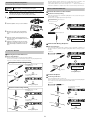
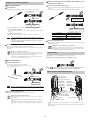
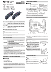
96M00603 FS-N10 Series Quick Start and Cabling Quick Start Digital Fiber Sensor Output switch Fine sensitivity adjustment FS-N10 Series Up Press the [MODE] button once, then use to select L-on or D-on Down Preset function Instruction Manual Configure easily with a single press when receiving light Setting value Light intensity Power select switch *1 Sensitivity setting Standard ⇔ MEGA (fixed) Press once each for workpiece/no workpiece *1 This is a channel switch on 2-output types. *2 Press and hold the [MODE] button to make advanced settings. Cabling Note See page 4 for information about connecting to external devices other than the FSN11N. Brown Danger Failure to follow these instructions may lead to death or serious injury. Warning Failure to follow these instructions may lead to injury. Caution Failure to follow these instructions may lead to product damage (product malfunction, etc.) Note Black Blue Load 0V Mounting Unit Mounting on a DIN Rail Provides additional information on proper operations that can be easily mistaken. 1 Note DC12-24V This provides tips about situations in which the feature being described is useful. Tip 2 See "FS-N10 Series User's Manual" for details on the features of the FS-N10 series and detailed instructions for configuration. 3 Align the claw at the bottom of the main body with the DIN rail, as shown in figure1. While pushing the main body in the direction of the arrow 1, slant it in the direction of the arrow 2. 2 1 figure1 To dismount the sensor, raise the main body in the direction of the arrow 3 while pushing the main body in the direction of the arrow 1. Installation on a Wall (Main Unit Only) Hints on Correct Use 1 • This product is used to detect targets. Do not apply the Attach the unit to the optional mounting bracket (OP73880), mount them together, and secure them with two M3 screws as shown in figure2. product to safety circuits for human protection. • This product is not of explosion-proof construction. Do not Warning use the products in places with flammable gas, liquid, or dust. • This product is a sensor of DC power supply type. Do not apply AC power. The product may explode or burn if an AC voltage is applied. OP-73880 figure2 Connecting Fiber Unit 1 • Do not wire the amplifier line along with power lines or high-tension lines, otherwise the sen• • • • sor may malfunction or receive damage due to noise. When using a commercially available switching regulator, ground the frame ground terminal and ground terminal. Do not use the FS series outdoors, or in a place where extraneous light can enter the lightreceiving surface directly. Due to the individual dispersion of characteristics and the difference in fiber unit model, the maximum sensing distance or displayed value of all the units are not the same. If the sensor is used in S-APC mode for a long time, the LED indicators will be imposed with a heavy load. In that case, the sensor will be automatically set to ACC mode where the current consumption of the sensor for light emission will be constant, and “END APC” will be displayed. The sensor can be continuously used in this case. Replace the sensor, however, if highly precise detection is required. 2 3 4 1 Move down the fiber lock lever in the direction shown by arrow 2. Insert a fiber unit into the fiber insertion holes to a length of the fiber insertion sign (i.e., approximately 14 mm). The FS-N series is UL and C-UL certified, and is compliant with the UL and CSA standards. • Applicable standards UL508 Industrial Control Equipment CAN/CSA C22.2 No.14-M05 Industrial Control Equipment • UL File No. E301717 • UL categories: NRKH, NRKH7 • Enclosure Type 1 (based on UL50 standard) Notes on UL Certification 4 2 3 Move down the fiber lock lever in the direction shown by arrow 4. Note About UL Certification Fiber insertion sign • If a thin fiber unit is used, an adapter provided with the thin fiber unit will be required. Unless the correct adapter is connected, the thin fiber unit will not detect targets correctly (the adapter is supplied with the fiber unit). Cable outer dia Adapter φ1.3 Adapter A (OP-26500) φ1.0 Adapter B (OP-26501) Appearance • To connect the coaxial reflective type fiber unit to the amplifier, connect the single-core fiber to the transmitter side, and connect the multiple-core fiber to the receiver side. • The power source used with the FS-N series must be UL Listing certified for Class 2 output • Open the dust cover in the direction shown by arrow 1. as stipulated by US National Electric Code (NEC) NFPA70. Connect the FS-N12 and N14 to the FS-N11 and N13 main units for use. Included accessories Single-core fiber • Instruction Manual 1pc. • Fiber cutter 1pc. Multi-core fiber 1 Transmitter Receiver Two-point calibration performs detection at a location where there is a workpiece, and another location where there is not, uses the intermediate value as the setting. If the sensitivity difference does not have enough room, "- - - -" flashes for about two seconds after the calibration is complete. The set value is stored in memory even in that case. Connecting Multiple Amplifiers Up to 16 sub units can be connected to one main unit. Warning Note 1 Mount on DIN rail and install on metal sheeting when connecting to multiple amplifiers or mounting main units together. Other Calibration Methods Increase Resistance to Dust and Dirt • Multiple connections cannot be made to equipment other than the FS-N10 series. • Turn the power off before connecting multiple sub units. • Do not touch the expansion connector with your bare hands. z Maximum Sensitivity Setting In the state shown below, press and hold the [SET] button for three seconds and stop pushing when "5'6" flashes. The sensitivity is set slightly higher than the light intensity. Remove the protection covers of the main unit and sub unit(s). Through-beam model : with workpiece set 2 Workpiece Install the amplifiers one by one on the DIN rail. Press and hold for 3 seconds or more 3 4 5 Engage the two claws of the sub unit with the recesses on the main unit side until you hear a click. Reflective model : without workpiece set Attach the end units (option: OP-26751) to the both ends of the connected amplifiers in the same way as in step (2). Press and hold for 3 seconds or more Sandwich the amplifiers between the end units. Tighten the screws at the top (two screws x two units) with a Phillips screwdriver to fix the end units. Calibrate with Moving Workpiece z OP-26751 (a set of two) Calibration Method Press and hold the [SET] button with no workpiece in place, while “5'6” is flashing, pass through a workpiece. (Continue pressing the [SET] button while the workpiece passes through.) Common to Through-beam and Reflective Models Detecting Even Small Differences z Full Auto Calibration Press and hold until "UGV" flashes Two-point Calibration Two-point calibration is the basic method for making calibration. You can set the sensitivity level automatically, simply by pressing the [SET] button twice. Just press once with the workpiece set up, and once without. Through-beam model setting method Press [SET] button once with no workpiece set While pressing the [SET] button pass through a workpiece Workpiece Settings complete Position Workpiece Press [SET] button once with workpiece set Workpiece z Positioning Calibration Press the [SET] button with no workpiece set. Place the workpiece in the location you wish to position it, and press and hold the [SET] button for at least 3 seconds. Release the button when "5'6" flashes. Common to Through-beam and Reflective Models Settings complete Press [SET] button once with no workpiece set Reflective model setting method Press [SET] button once with no workpiece set Press and hold [SET] button with workpiece set Press [SET] button once with workpiece set Workpiece Press and hold until "UGV" flashes Workpiece Settings complete Settings complete 2 Set the current value to an adequate value when it is too large (when saturated). Simple, User Friendly Functions Easily Set up Display z z Use the Saturation Recovery Function Press the [SET] button while pressing the [MODE] button to enable the saturation recovery function. The light transmission level and light intensity gain are calibrated automatically. Preset Function With light ON, press the [PRESET] button. The current value is set to "". Press [PRESET] button once with no workpiece set Press the [SET] button while pressing the [MODE] button. Green "PST" lights up Setting is "" Current value is "" Pressing the [PRESET] button changes the setting and current value as shown below. • Presetting with preset disabled: The setting is changed to "". The setting can be changed via the normal calibration method. • Presetting with preset enabled: Only the current value is changed to "", and the setting is not changed. Note z Set the light intensity to within the range in the table below. Power mode • The preset function cannot be used together with the zero shift function. To use the zero shift function, you must first disable the preset function. • This is not suited to transparent workpieces and other cases of detection with low light shielding. z Light intensity setting range HSP, FINE, TURBO 2047 r 350 SUPER 4095 r 500 ULTRA, MEGA 5000 r 600 Disable Saturation Recovery When the saturation recovery function is enabled, press the [SET] button while pressing the [MODE] button to cancel it. Disable the Preset Function Note Press and hold the [PRESET] button to disable the preset function. When the preset function is disabled, the ratio of the setting and current values is maintained as-is. Note Tip Tip Handy Uses for the Saturation Recovery Function This function is handy when the fiber unit becomes saturated after installation. This eliminates the saturation via a simple operation, by automatically calibrating the light transmission level and light intensity gain. Handy Uses for the Preset Function Output Switch This function is mainly useful when performing simple detection using a through-beam model fiber unit (e.g. complete dark detection, such as when all light axes of the fiber unit are shielded with opaque workpieces). Either light-ON (L-on) mode or dark-ON (D-on) mode can be selected. When you are using multiple FS-N10 series units simultaneously, this function is an easy way to make all the displays uniform. 1 While the current value is displayed, press the [MODE] button once. Set Current Value to "0" z The Zero Shift Function This function is mainly used with reflective models. Press the [PRESET] button and [ ] button at the same time. The current value is set to "0". 2 Use to switch the output (.QP/&QP), then press the [MODE] button again. The output switch completes, and the display returns to the current value. Names of Each Part of the Main Unit Fiber lock lever Green "PST" lights up SET button (SET) Operation status indicators PST indicator Setting value (Displayed in green) DTM indicator Current value is "" Digital monitor Note z Manual button ( ) The zero shift and preset function cannot be used together. To use the preset function, you must first disable the zero shift function. Current value (Displayed in red) Expansion protective cover Expansion connector Disable the Zero Shift Function Press and hold the [PRESET] button to disable the zero shift function. MODE button (MODE) Note Tip Handy Uses for the Zero Shift Function Preset button (PRESET) This function is mainly used to set the current value to "0" on a reflective model fiber unit. Cable*2 Power select switch*1 Dust cover When a reflective model is first installed, the light intensity is sometimes not set to "0". If this happens, using the zero shift function to set the value to "0" when there is no workpiece allows for easier understanding of the difference in light intensity. *1 Setting to "M" locks the power mode to MEGA mode. The two output type is a channel switch. *2 On the FS-N10Cx, this is an M8 connector rather than a cable. On the FS-N10Ex, this is an e-CON connector. 3 Connecting to External Devices Initializing the Settings FS-N11N/N12N/N11MN/N13N/N14N Initializing Method Input Circuit Diagram (FS-N13N/N14N only) Sensor main circuit Load DC5−30 V Black*3 (Control output) Press and hold the [SET] and [PRESET] buttons simultaneously for three seconds. Pink PLC, etc. (Short-circuit current 1 mA or less) Blue 0V 0V Blue*1 1 DC3.3 V DC12−24 V Brown*1 Monitor output(1−5V)*2 Device with input impedance Orange 10 Ω or more Protection circuit Sensor main circuit Overcurrent protection circuit Output Circuit Diagram *1 FS-N11N/N11MN/N13N only *2 FS-N11MN only *3 The FS-N13N/N14N has a white cable as separate output 2. Press and hold for 3 seconds or more 2 3 FS-N11P/N12P/N13P/N14P/N13CP/N14CP Output Circuit Diagram Input Circuit Diagram (FS-N13P/N14P only) Sensor main circuit Overcurrent protection circuit Sensor main circuit DC12−24 V z Brown DC12−24 V Brown 1*1 Black 4*2 Load (Control output) Blue 3*1 to select "456", then press the [MODE] button. Use the Use the to select "K0K6", then press the [MODE] button. After initialization is complete, the display returns to the current value. Initial Settings PLC, etc. Setting Initial Value Pink Power mode (Short-circuit current 2 mA or less) 0V FINE Detection mode 2 M8 connector Pin layout 1 4 3 *1 FS-N11P/N13P/N13CP only *2 The FS-N13P/N14P has a white cable as separate output 2. The FS-N13CP/N14CP has the pin2 as separate output2. Sensor main circuit Overcurrent protection circuit Sensor main circuit Load 1 2 DC3.3 V DC12−24 V 4 DC5−30 V 3* 1 2 (Short-circuit current 1 mA or less) 0V Fiber e-CON connector Pin layout 3 Fiber cutter (OP-87098) Always insert fiber from the end with writing Cautions for Using a Fiber Cutter FS-N11CP/N12CP Output Circuit Diagram Failure to heed the cautions below could reduce the detection range. Input Circuit Diagram DC12−24 V 1* • When cutting a fiber unit to be attached to the FS-N10 series, be sure to use a gray fiber cut- 1* Sensor main circuit DC12−24 V Overcurrent protection circuit 2 3* *FS-N11CN/N11EN only Sensor main circuit Bring down the blade in a single, swift motion to cut the fiber. 1 4 1 Inset the fiber into the cutter hole. PLC, etc. 0V M8 connector Pin layout L-on Using a Fiber Cutter Input Circuit Diagram 1* 50 Output switch Using a Fiber Cutter and Cautions for Use FS-N11CN/N12CN/N11EN/N12EN Output Circuit Diagram Normal Setting value 4 Load 0V ter (OP-87098) PLC, etc. • Stopping the blade midway could cause a bad cut plane, reducing the detection range. • Do not use the same hole twice. 2 (Short-circuit current 2 mA or less) 3* Function Configuration 2 M8 connector Pin layout 1 4 e-CON connector Pin layout 3 Basic Setting *FS-N11CP only MODE Press and hold Socket Cable (Sold Separately) for 3 seconds or more J52 (KPG 6WT$ 5W24 7.64 /')# For FS-N11CN/N11CP/N12CN/N12CP/N13CP/N14CP High Speed mode MODE OP-73864 (Cable length: 2 m) 4 3 OP-73865 (Cable length: 10 m) 2 1 Pin - Pin and wire color table Connected Core wire pin No. cover color 1 Brown 2 White 3 Blue 4 Black ErC Cause Overcurrent in the control output. End APC Super mode Ultra mode MEGA mode Normal sensitivity setting method MODE Solution Check the load and return the current within the rated value. MODE ErE Turbo mode 5'6 5VF 5'6 5'V2 5'6 15'V Error Displays and Corrective Actions Error display Fine mode Failed to write/load the internal data. Perform initialization (p.4). Large load on the light source. Replace the sensor if highly precise detection is required. '0& 5V) (W0E 5V) &K52 5V) 5;5 Percentage Calibration*1 Zero-shift calibration MODE Settings complete Go to detection setup mode Go to display setup mode Go to system setup mode Return to normal display *1 You can press the 4 MODE button to set between the range of 2 to 2. Detection Settings 5V) (W0E System Settings 5V) 5;5 MODE MODE 6Q(( Q((& Q0& 5JQ6 MODE 1 On-delay timer * MODE *7 MODE DATUM1 mode *2 MODE Area detection mode KPV( 56& KPV( &Q$. Rising Edge Detection Mode MODE Falling Edge Detection Mode Do not use external input .KP- Q(( .KP- *1 External calibration input Zero shift input MODE Reset input Transmission OFF input 3 Pause mode transition input * Sleep mode transition input MODE MODE MODE Return to original detection setup mode EJ #.TV 6Q(( Q((& Q0& 5JQ6 MODE *6 Only external input types (FS-N11CN/N11CP/N11EN/N12EN/N13N/N13P/N14N/N14P). *7 Only monitor output types (FS-N11MN). '0& Display Settings 5V) &K52 24* QP 24* Q(( MODE '0& 5V) 5;5 5V) (W0E 5V) &K52 *2 Press the MODE MODE Settings complete Go to detection setup mode Go to original display setup mode Return to system setup mode Light intensity detection mode Limit setting output mode User reset Auto reset Warning output mode Timer OFF Off-delay timer *1 On-delay timer *1 One-shot timer *1 Settings complete Return to normal display *1 Press the Normal display method MODE button to set between the range of and (ms). *2 Only 2 output types (FS-N13N/N13P/N14N/N14P/N13CP/N14CP). Reverse display Do not set up sub-display Extension display Bar display Excess gain display Light intensity hold display *1 Excess gain hold display *1 L-on / D-on display Enable the saturation of the Preset function *2 Disable the saturation of the Preset function Settings complete Go to system setup mode Go to detection setup mode Return to original display setup mode Return to normal display *1 Press the Enable common key operations MODE MODE MODE Twice number of interference-prevention units as 56& (response time 2 times slower) T5V 75'4 T5V #WVQ Go to system setup mode *5 Can be set between the range of and . 5W$ Q(( 5W$56&' 5W$ $#4 5W$ 2'4 5W$ *.& 5W$*.&2 5W$.FQP Normal operation MODE *4 Can be set between the range of and . MODE QP '0& 5V) (W0E 5V) &KU2 5V) 5;5 Go to display setup mode button to toggle between Q((/Q0/-''2. MODE Maximum current value display (4 times hysteresis) MODE Settings complete button to set between the range of and (ms). 4'W Q(( 4'W QP Standard current value display Two Output *2 EJ 5VF EJ .K/V Analog scaling *5 *2 Press the button to set the retouch sensitivity to a range of between .'W and .'W and set the warning output level to a range of between 12 and 2. *3 Press the Reduce power consumption (response time 4 times slower) *1 Main unit only. Light emission power selection * Return to normal display *1 Press the Enable eco feature Return to normal display 4 MODE Do not use eco feature Disable common key operations MODE Preset input #P.) '0& 5V) &K52 5V) 5;5 5V) (W0E )#KP 5VF )CKP (W.. DATUM2 mode *2 KP Q(( KP 5'V KP 245V KP 5J(V KP 45V KP .Q(( KP 2#75 KP 5.'2 Enable APC MODE Normal (light intensity) detection mode #66 MODE QP 'EQ Q(( 'EQ QP 'EQ (W.. One-shot timer *1 &'VE 5VF &'VE &V/ &'VE &V/ &'VE #4'# &'VE &'VE Disable APC MODE Off-delay timer *1 MODE *6 #2% Q(( #2% Timer OFF button to toggle between 5VF/2`2A/D`DA/2AD`/2`DA button to set between the range of 2 and 2. 5 Specifications Type Cable/M8 connector M8 connector*1 Cable Main unit/sub unit Model Monitor output Standard 1 output Sub unit e-CON connector*1 Sub unit High functionality 2 output Cable M8 connector*1 Cable Sub unit Sub unit Sub unit Main unit (with output cable) Main unit (with output cable) Main unit (with output cable) Main unit Main unit (with output cable) NPN FS-N11N FS-N12N FS-N11CN FS-N12CN FS-N11EN FS-N12EN FS-N11MN FS-N13N FS-N14N - - PNP FS-N11P FS-N12P FS-N11CP FS-N12CP - - - FS-N13P FS-N14P FS-N13CP FS-N14CP 2 output Control output Main unit (with output cable) 1 output 1 output 1 output 1 output 1 output 1 output 1 output 2 output 2 output 2 output Monitor output (1-5 V) - - - - - - 1 output - - - - External input - - 1 input 1 input 1 input 1 input - 1 input 1 input - - 50 Ǵs (HIGH SPEED)/250 Ǵs (FINE)/500 Ǵs (TURBO)/1 ms (SUPER)/4 ms (ULTRA)/16 ms (MEGA) Response time Control output NPN output NPN open collector 30 V; 1 output max: 100 mA or less; 2 output total: 100 mA or less (used stand-alone)/20 mA or less (multiple connections); residual voltage 1 V or less PNP output PNP open collector 30 V; 1 output max: 100 mA or less; 2 output total: 100 mA or less (used stand-alone)/20 mA or less (multiple connections); residual voltage 1 V or less Monitor output 1 to 5 V voltage output; load resistance 10 k: or more; repeat precision r 0.5% of F.S.; responsiveness 1 ms (FS-N11MN only) External input input time 2 ms (ON)/20 ms (OFF) or more Multiple connections to sub units Up to 16 units can be connected total, but two-output type is treated as two units Number of interference prevention units Rating 0 for HSP; 4 for FINE; 8 for TURBO/SUPER/ULTRA/MEGA (When set to double, the number of interference-prevention units will be doubled.) 12 - 24 V DC r 10% ripple (P-P) 10% or less Power voltage NPN Normal:900 mW or less (36 mA max. at 24 V, 48 mA max. at 12 V)*2 Eco on mode:800 mW or less (32 mA max. at 24 V, 39 mA max. at 12 V)*2 Eco Full mode:470 mW or less (19 mA max. at 24 V, 23 mA max. at 12 V) PNP Normal : 950 mW or less (39 mA max. at 24 V, 52 mA max. at 12 V)*2 Eco on mode : 850 mW or less (35 mA max. at 24 V, 44 mA max. at 12 V)*2 Eco Full mode : 520 mW or less (21 mA max. at 24 V, 26 mA max. at 12 V) Environme Operating ntal ambient resistance luminance : 1050 mW or less(42 mA max. at 24 V, 56 mA max. at 12 V)*2 Eco on mode : 950 mW or less(38 mA max. at 24 V, 47 mA max. at 12 V)*2 Eco Full mode : 600 mW or less(24 mA max. at 24 V, 29 mA max. at 12 V) Incandescent lamp: 20,000 lx or less; Sunlight: 30,000 lx or less Operating ambient temperature -10 to +55 q C (no freezing)*3 Operating ambient humidity 35 to 85% RH (no condensation) Vibration resistance 10 to 55 Hz Compound amplitude 1.5 mm, 2 hours for each of X,Y,Z axis Shock resistance 500 m/s2 3 times for each of X,Y,Z axis Case material Weight - Normal Both main unit and housing material: Polycarbonate Approx 75g Approx 45g Approx 22g Approx 22g Approx 22g Approx 22g Approx 75g Approx 80g Approx 70g Approx 22g Approx 22g *1 Use a cable length of 30m or less for M8 connector and e-CON connector types. *2 Increases 100 mW (4.0 mA) for High Speed mode *3 One or two more units connected: -10 to +55 q C; 3 to 10 more units connected: -10 to +50q C; 11 to 16 more units connected: -10 to +45q C. When using 2-outputs, one unit is counted as two units. All temperature regulations are for when the unit is mounted on a DIN rail and installed on metal sheeting. Warranties and Disclaimers KEYENCE CORPORATION 1-3-14, Higashi-Nakajima, Higashi-Yodogawa-ku, Osaka, 533-8555, Japan www.keyence.com PHONE: +81-6-6379-2211 KEYENCE, at its sole option, will refund, repair or replace at no charge any defective Products within 1 year from the date of shipment. Unless stated otherwise herein, the Products should not be used internally in humans, for human transportation, as safety devices or fail-safe systems. EXCEPT FOR THE FOREGOING, ALL EXPRESS, IMPLIED AND STATUTORY WARRANTIES, INCLUDING WARRANTIES OF MERCHANTABILITY, FITNESS FOR A PARTICULAR PURPOSE AND NONINFRINGEMENT OF PROPRIETARY RIGHTS, ARE EXPRESSLY DISCLAIMED. KEYENCE SHALL NOT BE LIABLE FOR ANY DIRECT, INDIRECT, INCIDENTAL, CONSEQUENTIAL OR OTHER DAMAGES, EVEN IF DAMAGES RESULT FROM THE USE OF THE PRODUCTS IN ACCORDANCE WITH ANY SUGGESTIONS OR INFORMATION PROVIDED BY KEYENCE. In some jurisdictions, some of the foregoing warranty disclaimers or damage limitations may not apply. AUSTRIA Phone: +43-2236-378266-0 BELGIUM Phone: +32 2 716 40 63 CANADA Phone: +1-905-696-9970 CHINA Phone: +86-21-68757500 CZECH REPUBLIC Phone: +420 222 191 483 FRANCE Phone: +33 1 56 37 78 00 GERMANY Phone: +49-6102-36 89-0 HONG KONG Phone: +852-3104-1010 HUNGARY Phone: +36 14 748 313 ITALY Phone: +39-2-6688220 JAPAN Phone: +81-6-6379-2211 KOREA Phone: +82-31-642-1270 MALAYSIA Phone: +60-3-2092-2211 MEXICO Phone: +52-81-8220-7900 NETHERLANDS Phone: +31 40 20 66 100 POLAND Phone: +48 71 36861 60 Specifications are subject to change without notice. Copyright (c) 2009 KEYENCE CORPORATION. All rights reserved. 00603E 0079-1 96M00603 Printed in Japan 6 SINGAPORE Phone: +65-6392-1011 SLOVAKIA Phone: +421 2 5939 6461 SWITZERLAND Phone: +41 43 455 77 30 TAIWAN Phone: +886-2-2718-8700 THAILAND Phone: +66-2-369-2777 UK & IRELAND Phone: +44-1908-696900 USA Phone: +1-201-930-0100 A6WW1-MAN-0059