1
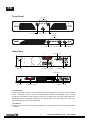
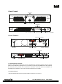
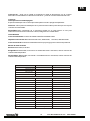
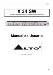
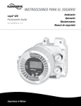
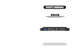
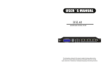
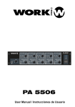
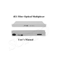
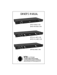
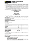
WCE 200
WCE 400
SIG
User Manual / Manual de Uso
Rev 1.0
EN
The information furnished in this manual does not include all of the details of design
and engineering of this particular product; not does it cover every possible application
or situation concerning its usage, which may occur during the installation, operation or
maintenance of said WORK product.
IMPORTANT
THE PRODUCT REQUIRES CLASS 2 OUTPUT WIRING.
CAUTION
TO PREVENT ELECTRIC SHOCK, DO
NOT REMOVE TOP OR BOTTOM
COVERS. NO USER SERVICEABLE
PARTS INSIDE. REFER SERVICING
TO QUALIFIED SERVICE
PERSONNEL. DISCONNECT
POWER CORD BEFORE REMOVING
REAR PANEL COVER TO ACCESS
GAIN SWITCH.
Shock Hazard - Do Not Enter
Choc Hasard - N*entrent
Schocke Hazard - Test Nicht
Betrete
Urto Hazard - Do Non Entrano
WARNING
TO REDUCE THE RISK OF ELECTRIC
SHOCK, DO NOT EXPOSE THIS
EQUIPMENT TO RAIN OR MOISTURE!
Magnetic Field
CAUTION: Do not locate sensitive high-gain equipment such as preamplifiers or
tape decks directly above or below this unit. Because this amplifier has a high
power density, it has a strong magnetic field which can induce hum into
unshielded devices that are located nearby. This field is strongest just above and
below the unit. If an equipment rack is used, we recommend locating the
amplifier(s) at the bottom of the rack and the preamplifier or other sensitive
equipment at the top.
The lightning bolt triangle is used alert the user to the risk of electric shock
The exclamation point triangle is used to alert the user to important operating
and/or maintenance instructions.
This symbol on the product or on its packaging indicates that this product
shall not be trated as household waste. Instead it shall be handed over to
the applicable collection point for the recycling of electrical an electronic
equipment. By ensuring this product is disposed of correctly, you will help
prevent potential negative consequences for the environment and human
health, which could otherwise be caused by inappropriate waste handling
of this product. The recycling of amterials will help to conserve natural
resources. For more detailed information sabout recycling of this product,
please contact your local city office, your household waste disposal service
or the shop where you purchased the product.
1
User Manual/Manual de Uso
WCE 200/400
EN
CONTENTS
1. Welcome
1.1 Unpacking
1.2 Features
3
3
2. Installation
2.1 Stereo
2.2 Mono
2.3 Required AC Mains
4
4
5
3. Operation
3.1 Precautions
3.2 Power Indicator
3.3 Protection Systems
3.3.1 Drive Protection
3.3.2 Signal Limiting Circuit
5
5
6
6
6
4. Specifications
6
2
User Manual/Manual de Uso
WCE 200/400
EN
Front Panel
Indicators
SIG
Ch.1 Level Control
Power Switdh
Ch.2 Level Control
Indicators
Ch.1 Level Control
Power Switdh
Ch.2 Level Control
Rear Panel
MODE SWITCH
FUSH
CHANNEL 1-2 (Outputs)
Power Input
FUSH
CHANNEL 1-2 (Inputs)
MODE SWITCH
FUSH
Power Input
FUSH
CHANNEL 1-2 (Inputs)
CHANNEL 1-2 (Outputs)
1.1 Unpacking
Please unpack and inspect your new amplifier for any damage that may have occurred during
transit. If damage is found, notify the Transportation Company immediately. Only you, the
consignee, may initiate a claim with the carrier for damage which occurred during shipment.
Remember to save all packing materials in the unlikely event your unit should ever need to be
returned to the factory for service of any kind.
1.2 Features
¡Rugged, road-worthy professional power amplifier. E.I.A. Standard 19" (48.3cm) rack-mountable
chassis.
3
User Manual/Manual de Uso
WCE 200/400
EN
¡ Front panel power switch with turn-on delay for loudspeaker protection.
¡ Patented Output Device Emulation Protection keeps the amplifier working under extreme
conditions.
¡Safe with any load. Bridge-Mono and Parallel-Mono modes offer optimal load-matching
performance.
¡Complete protection against shorted outputs, mismatched loads, overheating, DC input/output
and high frequency overload, full internal fault protection.
¡ Balanced XLR inputs with balanced direct XLR output. Optional barrier block input connectors
are available with the PM-BB accessories.
¡ One year "no-fault" full warranty and guaranteed specifications protect your investment.
2.1 Stereo
1. Turn down the level controls (fully counterclockwise) and turn off the amplifier.
2. Set the back panel Stereo/Mono switch to Stereo.
3. Connect the input and output cables .
4. Turn on the amplifier and adjust the level for each channel using the front panel level controls.
2.2 Mono
Your amplifier's Mono modes provide double the power of the Stereo mode in a single channel. In
Bridge-Mono mode, the outputs are wired for twice the output voltage. In Parallel-Mono mode, the
inputs are paralleled to link the two channels. Bridge-Mono mode is provided for loads with
impedance greater than 4 Ohms. Parallel-Mono mode should be used with loads of 4 Ohms .
Bridge-Mono
1. Turn down the level controls (fully counterclockwise) and turn off the amplifier.
2. Set the back panel Stereo/Mono switch to Bridge-Mono.
3. Connect the input and output cables. Only channel 1 input is used.
4. Make sure the load is balanced (neither side shorted to ground) and do not use the black (-)
binding posts.
5. Turn on the amplifier and adjust both level controls.
Parallel-Mono
1. Turn down the level controls (fully counterclockwise) and turn off the amplifier.
2. Set the back panel Stereo/Mono switch to Parallel-Mono.
3. Connect the input and output cables as shown in the Only channel input is used.
4. Turn on the amplifier and adjust both level controls.
CAUTION: Never strap the two red output terminals together (in parallel). Never connect
either red output terminal to chassis ground.
IMPORTANT: The channel 2 level control will remain illuminated when operating in
Parallel/Mono mode.
4
User Manual/Manual de Uso
WCE 200/400
EN
2.3 Required AC Mains
The WCE Series amplifiers are shipped with an appropriate line cord and plug. When possible,
use a power receptacle on a dedicated circuit; and always, make sure it will provide the correct
voltage and sufficient current. We do not recommend operating your amplifier with voltages
greater than 10% above or below the unit's rated voltage. For example, if your amplifier is rated for
220 VAC, the line voltage should not exceed 240 VAC.
CAUTION: Connect unit only to a proper supply. Use only three wire cord which is provided with
unit.
3 Operation
3.1 Precautions
Although your amplifier is protected from external faults, the following safety precautions are
recommended:
1. There are important differences among the Stereo, Bridge-Mono and Parallel-Mono operating
modes. Please refer to Section 2 for additional information.
2. WARNING: Do not change the position of the stereo/mono switch unless the amplifier is
first turned off .
CAUTION: Never strap the two red output terminals together (in parallel). Never connect
either red output terminal to chassis ground.
Also, make sure the Stereo/Mono switch is set to the proper position.
3. Use care when making connections, selecting signal sources and controlling the output level.
4. Do not short the ground lead of an output cable to the input signal ground. This will form a
ground loop and may cause oscillations.
5. Do not operate the amplifier from AC mains in excess of 10% variation above or below the
selected line voltage, and only at the specified line frequency.
6. Never connect the output to a power supply output, battery or power main. Such connections
may result in electrical shock.
7. Tampering with circuitry by unqualified personnel or making unauthorized circuit changes may
be hazardous and invalidates warranty.
3.2 Power Indicator
When illuminated, the green power indicator (the volume control) shows that the amplifier has
been turned on.
3.3 Protection
WCE Series amplifiers are protected against shorted circuits or mismatched loads, overloaded
power supplies, excessive temperature, chain destruction phenomena, input overload and
high frequency blowups. They also protect loudspeakers from input and output DC and
provide protection from turn-on/turn-off transients.
If operating conditions are unreasonable, the patented circuitry proportionally limits the drive
level to protect the output transistors, particularly in the case of elevated temperature. A
thermal switch imbedded on the heat-sink protects the output device from overload.
5
User Manual/Manual de Uso
WCE 200/400
EN
3.3.1 Drive Protection
The Drive Protection System temporarily removes output drive to protect the amplifier and its
loads. Drive Protection System can be activated in two situations. First, if dangerous subsonic
frequencies or direct current (DC) is detected in the amplifier's output, the unit will activate its
DC/low-frequency protection circuitry, which puts the amplifier in Drive Protection mode. This
mode protects the loads and prevents oscillations. The unit resumes normal operation as soon
as the amplifier no longer detects dangerous output. Although it is extremely unlikely that the
DC/low-frequency protection system will ever be activated, improper source materials like
subsonic square waves or input over-loads, that excessively clip the input signal, can activate
this system.
The amplifier's protection system will activate the amplifier's Drive Protection mode in rare
situations where heavy common-mode current is detected in the output. The unit should
never output heavy common-mode current unless its circuitry is damaged. Activating Drive
Protection mode helps prevent further damage.
3.3.2 Signal Limiting Circuit
This internal limiting circuit automatically reduce gain because of a significant deviation
between input and output signal flow, preventing occurrence of gross non-linearity conditions
inside the amplifier caused by overdrive, overload or defect, and keeps the signal shape
unaltered under any conditions. The circuit keep signal flow distortion under 0.5%, and thus
guarantees clean sound and effective speakerprotection.
4 Specifications
All amplifier specifications apply to the following settings: Stereo mode with 8-ohm loads and an
input sensitivity of 32dB, unless otherwise specified.
Power Specification
Output Power: The following specifications are guaranteed minimums for standard 1 kHz power.
For more information, see the closed table (maximum average power @ 0.1% THD +N).
Load Impedance: Safe with all types of loads. Rated at 4 to 8 ohms in Stereo, 4 to 8ohms in
Bridge-Mono and 4 to 8 ohms in Parallel-Mono mode.
Required AC Mains: Current, frequency and voltage requirements are provided on each unit's
back panel.
WCE 200: (220/50Hz)
8 A of current.
WCE 400: (220/50Hz)
10 A of current.
6
User Manual/Manual de Uso
WCE 200/400
EN
AC Connector: An appropriate AC line cord and plug are provided. 220 VAC, 50Hz/60Hz units
have a standard 3-wire, 15-amp grounded connector
Controls
Power: A front panel switch is used to turn the amplifier on and off.
Level: A front panel rotary potentiometer for each channel is used to control the output level.
Stereo/Mono:A three-position back panel switch is used to select Stereo, Bridge-Mono or
Parallel-Mono mode.
Input/Output Data
Input Connector: Balanced XLR connector and RCA unbalanced.
Input Impedance: Nominally 20k ohms, balanced; 10 k ohms, unbalanced.
Output Connector: Two sets of color-coded 5-way binding posts (for banana plugs, spade lugs or
bare wire) .
Output Signal Modes
Stereo: Balanced, two-channel.
Bridge-Mono: Balanced, single-channel. Channel 1 inputs are active; Both channel volume
controls are available.
Parallel-Mono: Balanced, single-channel. Channel 1 inputs are active; Both channel volume
controls are available.
WCE200
WCE400
0.05%
0.05%
8 ohm per Channel
150W
220W
4 ohm per Channel
220W
380W
8 ohm bridged
500W
800W
S/N Ratio
>65dB
>67dB
Slew rate
5V/us
5V/us
MODEL
THD
Power Handling
300
Damping factor
Mode switch
300
Stereo/Parallel/ Bridge
Stereo/Parallel/ Bridge
Crosstalk
>46dB
>46dB
Power ON delay
7 sec
7 sec
Input Sensitivity
0.7V
0.8V
< +/- 0.25dB
< +/- 0.25dB
Frequencie response 20-20KHz
Input connection
XLR
XLR
Link connection
RCA
RCA
Binding post
yes
Binding post
yes
Output connection
Soft start
Operating Voltage
Dimension/WxDxH/mm
Net weight
185-245V
185-245V
483x277x44
483x277x89
3.7kg
4.5kg
7
User Manual/Manual de Uso
WCE 200/400
ES
IMPORTANTE
ESTE PRODUCTO REQUIERE CABLEADO DE SALIDA CLASE 2
PRECAUCION
PARA PREVENIR
EL RIESGO DE
DESCARGA, NO RETIRE LAS TAPAS
SUPERIOR E INFERIOR, NO HAY PARTES
DE USO EN EL INTERIOR. DIRIJASE A UN
TECNICO ESPECIALIZADO. DESCONECTE
EL CABLE DE RED ANTES DE QUITAR LAS
TAPAS
Shock Hazard - Do Not Enter
Choc Hasard - N*entrent
Schocke Hazard - Test Nicht
Betrete
Urto Hazard - Do Non Entrano
ATENCION
PARA REDUCIR EL RIESGO DE
DESCARGA, NO EXPONGA LA
UNIDAD A LA LLUVIA O HUMEDAD
Campo Magnetico
PRECAUCION: No situe equipos de gran sensibilidad como previos o pletinas
directamente sobre esta unidad, debido al campo magnetico presente en estas
unidades, los cuales pueden inducir ruidos y zumbidos
El triangulo le alerta del riesgo de descargas
El punto de exclamación le alerta de una instrucción importante
Este símbolo en su equipo o embalaje, indica que el presente producto
no puede ser tratado como residuos domésticos normales, sino que deben
entregarse en el correspondiente punto de recogida de equipos electrónicos
y eléctricos. Asegurándose de que este producto es desechado
correctamente, Ud. está ayudando a prevenir las consecuencias negativas
para el medio ambiente y la salud humana que podrían derivarse de la
incorrecta manipulación de este producto. EL reciclaje de materiales
ayuda a conservar las reservas naturales. Para recibir más información,
sobre el reciclaje de este producto, contacte con su ayuntamiento, su
punto de recogida más cercano o el distribuidor donde adquirió el producto.
8
User Manual/Manual de Uso
WCE 200/400
ES
CONTENIDO
1. Bienvenida
1.1 Desembalando la unidad
1.2 Características
10
10
11
2. Instalación
2.1 Estéreo
2.2 Mono
2.3 Alimentación AC requerida
11
11
11
12
3. Funcionamiento
3.1 Precauciones
3.2 Indicador de potencia
3.3 Protecciones
3.3.1 Drive Protection
3.3.2 Limitador de señal
12
12
12
12
13
13
4. Especificaciones
13
9
User Manual/Manual de Uso
WCE 200/400
ES
Panel Frontal
Indicadores
SIG
Canal 1 (Control de nivel)
Canal 2 (Control de nivel)
Interruptor de encendido
Indicadores
Canal 1 (Control de nivel)
Canal 2 (Control de nivel)
Interruptor de encendido
Panel Trasero
CONMUTADOR DE MODO
FUSH
Alimentación
CANALES 1-2 (Salidas)
FUSH
CANALES 1-2 (Entradas)
MODE SWITCH
FUSH
Power Input
CANALES 1-2 (Salidas)
FUSH
CANALES 1-2 (Entradas)
1.1 Desembalando la unidad
Por favor, desembale e inspeccione su nuevo amplificador en busca de cualquier daño que pueda
haber ocurrido durante el transporte. Si lo encuentra, notifíquelo inmediatamente a la compañía
de transporte para proceder a la reclamación. Recuerde conservar todos los materiales de
embalaje para el hipotético caso en que sea necesario devolver la unidad.
1.2 Características
- Robusto amplificador de potencia profesional en formato de 1 HU rack 19".
10
User Manual/Manual de Uso
WCE 200/400
ES
-
Interruptor de encendido en el panel frontal con delay para la protección de los altavoces.
-
Dispositivo de salida patentado con emulación de protección de salida para proteger el
amplificador mientra trabaja bajo condiciones extremas.
-
Seguro con cualquier carga. Modos Bridge-mono y Parallel-mono ofrecen un óptimo rendimiento.
-
Completa protección ante cortocircuitos en la salida, desigualdades de la carga,
sobretemperatura, DC en entrada/salida y sobrecarga por alta frecuencia. Protección totalmente
interna.
-
Conectores de entrada XLR balanceados y RCA desbalanceados.
2.1 Estéreo
1. Gire los controles de ganancia al mínimo (totalmente en sentido antihorario) y apague el
amplificador.
2. Configure el conmutador Stereo/Bri/Par a la posición Stereo.
3. Conecte los cables de entrada y salida
4. Encienda el amplificador y configure la ganancia de cada canal usando los controles frontales.
2.2 Mono
Su amplificador dispone de modos Mono que permiten doblar la potencia del modo estéreo en un
sólo canal. En modo Bridge, la salida se obtiene doblando la tensión de salida. En modo Parallel,
las entradas se conectan en paralelo. El modo Bridge se utiliza para cargas superiores a los4
ohmios y el modo paralelo suele usarse con cargas de 4 ohms.
Bridge-mono
1. Gire los controles de ganancia al mínimo (totalmente en sentido antihorario) y apague el
amplificador.
2. Configure el conmutador Stereo/Bri/Par a la posición Bridge.
3. Conecte los cables de entrada y salida. Sólo se usa la entrada de canal 1
4. Asegúrese que la carga es correcta (no está derivada a masa) y no utilice los terminales (-) de
salida.
5. Encienda el amplificador y configure la ganancia de cada canal usando los controles frontales.
Parallel-mono
1. Gire los controles de ganancia al mínimo (totalmente en sentido antihorario) y apague el
amplificador.
2. Configure el conmutador Stereo/Bri/Par a la posición Parallel.
3. Conecte los cables de entrada y salida. Conecte señal de entrada sólo en un canal.
4. Encienda el amplificador y configure la ganancia de cada canal usando los controles frontales
PRECAUCION: Nunca puentee los 2 terminales rojos de salida. Nunca conecte el terminal
rojo a masa o chasis.
IMPORTANTE: El control de ganancia del canal 2 estará iluminado mientras la unidad
funcione en modo Parallel.
11
User Manual/Manual de Uso
WCE 200/400
ES
2.3 Alimentación AC requerida
La serie de amplificadores WCE viene equipada con el adecuado cable y conector para
alimentarla. A ser posible, utilice una toma propia y asegúrese siempre de que a la unidad se le
suministra el correcto voltaje y corriente. No es recomendable hacer funcionar la unidad con una
tensión de entrada de alrededor del 10% superior al valor marcado. Por ejemplo, si el amplificador
va a ser conectado a 220V, no deben superarse los 240V en la toma.
PRECAUCION: Conecte la unidad sólo a una toma adecuada. Utilice sólo el cable de 3
conductores suministrado junto con la unidad.
3 Funcionamiento
3.1 Precauciones
A pesar de que su amplificador está protegido de fallos externos, le recomendamos las siguientes
precauciones de seguridad:
1. Hay diferencias importantes en los modos de funcionamiento Stereo, Bridge y parallel. Diríjase
al apartado 2 para información adicional.
2. AVISO: No cambie la posición del switch de modo a menos que el amplificador esté
apagado.
PRECAUCION : Nunca puentee los 2 terminales rojos de salida. Nunca conecte el
terminal rojo a masa o chasis.
Asimismo, asegúrese que el conmutador Stereo(Mono está en la posoción adecuada.
3. Use las conexiones con cuidado, seleccionando fuentes de señal y controlando niveles de
salida.
4. No puentee un terminal de masa del cable de salida a un terminal de masa de la entrada. Creará
un bucle que podría causar oscilaciones.
5. No opera la unidad con un 10% de más en el voltaje de alimentación y sólo a la frecuencia de
línea especificada.
6. Nunca conecte la salid a una toma de alimentación o batería. estas conexiones podrían
provocar descargas eléctricas.
7. Forzar la circuitería por parte de personal no cualificado o hacerlo cambios internos no
autorizados puede ser peligroso e invalidad la garantía.
3.2 Indicador de potencia
Cuando se ilumina, el indicador verde muestra que el amplificadro está encendido.
3.3 Protecciones
Los amplificadores de la serie WCE están protegidos ante cortocircuitos o desajuste de la
carga, sobrecargas, temperatura elevada, sobrecarga de entrada y picos de alta frecuencia.
Además, protege a ,los altavoces conectados de voltajes DC en entradas/salidas y picos al
encender/apagar el amplificador.
Si las condiciones de funcionamiento no son óptimas, la circuitería interna limita el nivel para
proteger los transistores de salida, particularmente en caso de elevada temperatura. Un sensor
térmico colocado en el radiador protege al dispositivo de sobrecargas.
12
User Manual/Manual de Uso
WCE 200/400
ES
3.3.1 Drive Protection
El sistema de protección Drive protection desconectará temporalmente la salida para
proteger el amplificador y su carga. Este sistema puede activarse en dos situaciones.
Primera, si se detectan frecuencias subsónicas peligros o DC en la salida, la unidad
activará su circuitería de protección DC/baja frecuencia, la cual pondrá el amplificador en
modo protección. Este modo protege la carga y previene oscilaciones. La unidad recupera
el modo normal tan pronto como el amplificador deja de detectar estas anomalías. A pesar
que el sistema de protección DC/baja frecuencia se active, una fuente de señal
inadecuada, ondas cuadradas subsónicas o sobrecarga de entradas que clipean
excesivamente la señal de entrada, puede activar el sistema.
3.3.2 Limitador de Señal
Esta circuitería de limitación interna reduce automáticamente la ganancia si se produce una
desviación significativa entre el flujo de entradas y salida, previniendo condiciones de no
linealidad dentro del amplificador causadas por sobrecarga, o avería, y mantiene la integridad
de la señal inalterada bajo cualquier condición. El circuito mantiene el flujo de distorsión por
debajo del 0.5%, garantizando un sonido diáfano y una protección efectiva.
4 Especificaciones
Todas las especificaciones del amplificador aplican las siguientes configuraciones: Modo estéreo
con carga a 8 ohmios y una sensibilidad de entrada de 32 dB, a menos que se especifique lo
contrario.
Especificaciones de Potencia
Potencia de salida: Las siguientes especificaciones están realizadas con standard de 1 kHz.
Para más información, compruebe la tabla adjunta. (máxima potencia @ 0.1% THD +N).
Impedancia de carga: Segure con cualquier tipo de carga. Considerado a 4 y 8 ohms en Stereo, 4
y 8 ohms en Bridge-Mono and 4 y 8 ohms en Parallel-Mono.
Alimentación AC requerida: Los requerimientos de corriente, frecuencia y voltaje, son
marcados en el panel trasero de cada unidad.
WCE 200: (220/50Hz)
8 A de crriente
WCE 400: (220/50Hz)
10 A de corriente
13
User Manual/Manual de Uso
WCE 200/400
ES
Conector AC: Junto con la unidad se suministra un cable de alimentación con el conector
adecuado. Para Se trata de un cable de 3 conductores y conector con terminal de masa de 15A.
Controles
Interruptor de encendido/apagado:
El panel frontal dispone de un interruptor usado para encender o apagar el amplificador.
Ganancia: A En el panel frontal dispone de un potenciómetro rotativo para canal que se usa para
controlar el nivel de salida.
Stereo/Mono:AUn conmutador de 3 posiciones situado en el panel trasero se usa para
seleccionar el modo de funcionamiento: Stereo, Bridge-Mono o Parallel-Mono.
Entrada/Salida
Conector de Entrada: Conector XLR balanceado/RCA desbalanceado
Impedancia de entrada: Nominalmente 20k ohms, balanceado; 10 k ohms, desbalanceado.
Conector de salida: 2 sets de terminales Bindon Post (rojo/negro) para conectores tipo banana.
Modos de señal de salida
Estereo: Balanceada, 2 canales.
Bridge-Mono: Balanceada, monocanal. La entrada del canal 1 está activa, ambos controles de
volumen están disponibles.
Parallel-Mono: Balanceada, monocanal. La entrada del canal 1 está activa, ambos controles de
volumen están disponibles.
WCE200
WCE400
0.05%
0.05%
8 ohm por canal
150W
220W
4 ohm por canal
220W
380W
8 ohm modo bridge
500W
800W
Relación S/N
>65dB
>67dB
Slew rate
5V/us
5V/us
MODELO
THD
Potencia de manejo
Factor Damping
Modos de funcionamiento
300
300
Stereo/Parallel/ Bridge
Stereo/Parallel/ Bridge
Crosstalk
>46dB
>46dB
Retardo de encendido
7 sec
7 sec
Sensibilidad de entrada
0.7V
0.8V
< +/- 0.25dB
< +/- 0.25dB
Respuesta en frecuencia 20-20KHz
Conexionado de entrada
XLR
XLR
Conexionado Link
RCA
RCA
Binding post
Si
Binding post
Si
Conexionado de salida
Soft start
Alimentación
Dimensiones /AnxPrxAl/ mm
185-245V
185-245V
483x277x44
483x277x89
3.7kg
4.5kg
Peso
14
User Manual/Manual de Uso
WCE 200/400
EQUIPSON, S.A.
Avda. El Saler, 14 - Pol. Ind. L´Alteró
46460 - Silla (Valencia) Spain
Tel. +34 96 121 63 01 Fax + 34 96 120 02 42
www.equipson.es / [email protected]