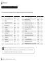
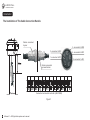
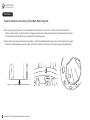
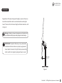
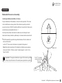
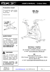
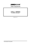
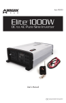
1
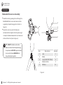
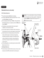
Airforce4.1
5KW grid-tied system
User’s manual
2011 Edition
HOPEFUL
WIND ENERGY TECHNOLOGY
Hopeful Wind Energy Technology Co., Ltd.
Congratulations on your purchase and welcome to our family!
Dear Airforce 4.1 Owner,
Thank you for your purchase of Airforce 4.1. You have just selected the most cost-effective, technologically advanced
renewable energy appliance available for a home or small business. We congratulate you on your choice and are confident you
will experience years of dependable service.
Before going any further, please complete and return the enclosed Warranty Registration Card, or register online via
www.hopefulenergy.com. The conditions of your warranty are dependent upon the proper installation of Airforce 4.1.
Furthermore, this will assure you of being kept up-to-date with the latest developments from Hopeful Wind Energy. These
include new options, performance tips, updated software to maximize output and user notices. It is important to know that we
do not sell or distribute your information to any third party. We understand your privacy is important. Please call during working
hours (Monday-Friday 8:30 am to 5:00 pm – Beijing time). Our phone number is +86 756-3819866 or 3819868, or you can
contact us by [email protected].
Again, welcome to our family and thank you for investing in the future of wind energy with Airforce 4.1.
Sincerely,
Hopeful Wind Energy Technology Co., Ltd.
HOPEFUL
WIND ENERGY TECHNOLOGY
Table of Contents
1 Basic Components
1
Installation
17
3
Electrical Connections To Airforce 4.1
17
Main Functions of The Controller
3
Wire Sizing
18
Electrical Circuit Chart of The Controller
3
Grounding
19
Technological Specifications of The Controller
4
Requirements of Installation—Controller for 5 kw
5
Grid-tied System
20
3 Curves of Performance
6
The Use of Cable Connection Handle
23
4 Important Safety Instructions
6
Installing Airforce 4.1 On A Tower
25
5 The Content of Your Airforce 4.1 Shipment
8
Bolting Airforce 4.1 To The Tower
30
6 Airforce 4.1 Limited 5-Year Warranty
9
Blades And Nosecone Assembly
31
Final Electrical Tests
34
8 Operation And Maintenance
35
Introduction of The Controller
2 Technical Specifications
WIND TURBINE WARRANTY AGREEMENT
7 Installation
9
12
12
Manual Operation of Airforce 4.1
35
Intended Use
12
Maintenance
35
Unintended Use
12
Service
36
Prior to Installation
Installation Personnel
13
Troubleshooting
36
Sequence of Installation
13
Emergency Shutdown
36
Typical Airforce 4.1 Installation
14
Key Operating Characteristics
37
Sitting—Finding the Best Location for Airforce 4.1
15
Disposal of Airforce 4.1
38
Local Requirement
15
Frequently Asked Questions
38
Choosing A Proper Site for Aiforce 4.1
16
Warranty Registration Card
Attachment
HOPEFUL
WIND ENERGY TECHNOLOGY
Basic Components
2
5
3
1
10
11
Descriptions
Item
4
3
9
8
6
7
Quantity
1
Hub
1
2
Blade
3
3
Long U bolt M10-105mm
6
4
Blade root shim
3
5
M10 Nut
24
6
Nosecone
1
7
Bolt M10-80mm
1
8
1
9
Nut M30 x 12
Spring washer Φ31mm
10
Woodruff key
1
11
Generator
1
12
Nylon sheath
1
1
12
Airforce4.1 — 5KW grid-tied system user’s manual
1
HOPEFUL
WIND ENERGY TECHNOLOGY
13
14
15
16
Quantity
17
20
13
Bolt M12 x 85mm
14
21
15
Washer 50-Φ12.5mm
Suspension rubber washer A
8
18
16
Suspension rubber washer B
8
17
Tower flange Φ240-Φ120 mm
1
18
Flat gasket 25-12.5mm
8
19
M12 Nut
8
20
Cover of vibration isolator
3
21
Socket head screw M6 x 8mm
6
22
M6 bolt
2
19
2
Descriptions
Item
Airforce4.1 — 5KW grid-tied system user’s manual
22
8
8
HOPEFUL
WIND ENERGY TECHNOLOGY
Introduction of The Controller
This manual is applicable for 5KW grid-tied wind power generator unit and its power generation system.
Main functions of the controller
● It adopts an embeded microprocessor as its core control unit with PWM function.
● It possesses a dual protection function—automatic braking of wind turbine over-loading(over-loading of voltage and current)
and emergency stop.
● Protection against over-charging of battery.
● Protection against reverse connection of battery.
● Protection against electrical shock and voltage surges.
Electrical circuit chart of the controller
Transformer
Rectifier
bridge
Charging
control
Electromagnetic Stable Power supply
braking control for braking system
Battery
AC
DC
+
Municipal grid input
-
AC
DC
Wind power
generator
circuit input
Switch of automatic Switch of manual
emergency brake
emergency brake
Voltage meter
Current meter
Airforce4.1 — 5KW grid-tied system user’s manual
3
HOPEFUL
WIND ENERGY TECHNOLOGY
Introduction of The Controller
Main technological specifications of the controller refer to table 1.
Table 1
Item
Max output alternating current voltage(V)
Max output current(A)
Max output power of the generator(KW)
The capacity of battery
The protection voltage of over-charging(V)
The recovery voltage of over-charging(V)
Time of automatic braking resuming
438
8
6
24V 100Ah
28.8
26
36 hours
Electrical source output of electromagnetic braking
150W/24V
Voltage of exterior working electrical source
220V/110V
The protection grade of controller's crust
Ip20
Applied temperature(℃)
0–45
Operating height above sea level(M)
≦1500
The external size of controller (MM)
370(W)x260(H)x184(D)
The total weight of controller(KG)
4
Spec.
Airforce4.1 — 5KW grid-tied system user’s manual
10.7
HE-W385B
Controller for 5 kw grid-tied system
HOPEFUL
WIND ENERGY TECHNOLOGY
Technical Specifications
Model
Airforce 4.1 – 5 KW grid-tied system
Max. output power
5 KW
Rated wind speed
12 M/S(27 MPH)
Max. wind speed
25 M/S(56 MPH)
Survival wind speed
60 M/S(134 MPH)
Start-up wind speed
1.8 M/S(4 MPH)
Cut-in wind speed
3 M/S(7 MPH)
Long U bolt M10-105mm
Rated rotational speed
500 RPM
Long U bolt M10-105mm
Max. rotational speed
550 RPM
No. of blades
3
Rotor diameter
4.1 M
Blade length
2.02 M
Blade material
FRP
Generator
3 Phases PM Generator
Braking system
Electromagnetic braking system control
Type
Downwind rotor
Yaw
passive
Total weight
Warranty
120 KG
5 years
Controller
Protection controller for generator
Grid-tided inverter
120/240Vac ,50/60Hz (optional)
Tower
12 M(optional)
Blade
Blade root shim
M10 Nut
Hub
Woodruff key
Spring washer
Generator
Φ31mm
Nut M30 x 12
Nosecone
Bolt M10-80mm
Nylon sheath
Airforce4.1 — 5KW grid-tied system user’s manual
5
HOPEFUL
WIND ENERGY TECHNOLOGY
Important Safety Instructions
Curves of Performance
Curves of Performance--5 kw grid-tied system.
Read these instructions in their entirety before installing or
operating.
6400
6000
Professional installation: Hopeful Wind Energy strongly
recommends Airforce 4.1 be installed by trained professionals.
5600
5200
1) SAVE THESE INSTRUCTIONS. This manual contains
important instructions for Airforce 4.1 that must be followed
during installation and maintenance.
4800
4400
2) Read, understand and respect all warnings.
4000
3) Do not install Airforce 4.1 around standing water.
Power(w)
3600
4) Do not install Airforce 4.1 on a windy day. The allowed wind
speed should be less than 2 m/s(4mph).
3200
5) Install Airforce 4.1 in accordance with local related electric
code and local building codes.
2800
2400
6) If required by local authorities, always obtain a building permit
before construction.
2000
1600
7) A minimum of 2 adults are required to safely lift or move
Airforce 4.1. Use proper equipment such as hydraulic hoists to
lift Airforce 4.1.
1200
800
8) Always wear appropriate protective personal equipment such
as closed toe work shoes, hard hat, work gloves, and safety
glasses when working on or installing Airforce 4.1.
400
m/s
mph
0
0
2
5
4
9
6
13
8
18
10
22
12
27
14
31
16
36
Wind Speed
6
Airforce4.1 — 5KW grid-tied system user’s manual
18
40
20
45
22
49
24
53
26
58
28
62
9) If unusual noise or abnormal operation is observed from
Airforce 4.1, turn off the machine and contact authorized
service personnel.
HOPEFUL
WIND ENERGY TECHNOLOGY
Important Safety Instructions
10) Shut Airforce 4.1 “OFF” if ice accumulates on blades to avoid
possible injury resulting from ice flying off blades.
11) This wind generator complies with international safety standards
and therefore the design or its installation must never be
compromised.
a. Do not open the nacelle cover , doing so without factory
14) Airforce 4.1 must be installed in accordance with this manual
and local and national building codes. Failure to comply with
the manual and local codes will affect and possibly void your
warranty.
15) Airforce 4.1 uses high voltage and is potentially dangerous.
Be sure to use all safety precautions at all times.
authorization will void the warranty.
b. Apply the proper torque to all fasteners.
c. Torque field wire connections to Airforce 4.1 to 2.3-2.5 N·m.
Refer to Electrical Connections section of this manual (electrical
In this manual
IMPORTANT: Please take note
connections to Airforce 4.1 on page 17).
d. Install only on a Professional Engineer (PE) certified tower.
TIP: Helpful information to ease the installation
e. Do not paint the blades.
Professional installation: highly recommended
12) Use only proper grounding techniques as established by local
related electric code.
Warning: Risk of injury or death - proceed with extreme
caution
13) Properly complete the warranty registration card (or you can log
on our website www.hopefulenergy.com to finish its electronic
format); failure to complete and return the card may affect your
warranty.
Airforce4.1 — 5KW grid-tied system user’s manual
7
HOPEFUL
WIND ENERGY TECHNOLOGY
The Content of Your Airforce 4.1 Shipment
When you've received the shipment of Airforce 4.1, please check all parts should be included as followed:
Descriptions
Item
Part No. Quantity
1
Hub
A05
1
2
Blade
A06
3
Long U bolt M10-105mm
A10
Descriptions
Item
Part No. Quantity
13
Bolt M12 x 85mm
B24
8
3
14
Washer 50-Φ12.5mm
B32
8
6
15
Suspension rubber washer A
B22
8
16
Suspension rubber washer B
B23
8
4
Blade root shim
A07
3
5
M10 Nut
A12
24
17
Tower flange Φ240-Φ120 mm
B21
1
6
Nosecone
A02
1
18
Flat gasket 25-12.5mm
B25
8
7
Bolt M10-80mm
A01
1
19
M12 Nut
B26
8
8
Nut M30 x 12
A03
1
20
Cover of vibration isolator
B29
3
9
Spring washer Φ31mm
A04
1
21
Socket head screw M6 x 8mm
B30
6
10
Woodruff key
A13
1
22
M6 bolt
B28
2
11
Generator
A33
1
23
Controller(HE-W385B)
B33
1
12
Nylon sheath
B15
1
24
Cable connection handle
B31
1
25
Earthing wire 10 AWG (6 mm )100mm
B27
1
2
TIP: Every part equipped to Airforce 4.1 has its own part number. If there is any fault found on these
parts during the installation or operation, you can contact Hopeful Energy or your local dealers by
tracking these part numbers for timely repair or replacement.
8
Airforce4.1 — 5KW grid-tied system user’s manual
HOPEFUL
WIND ENERGY TECHNOLOGY
Airforce 4.1 Limited 5 — Year Warranty
WIND TURBINE WARRANTY AGREEMENT
Hardware Warranty
Hopeful Wind Energy Technology Co., Ltd. (“Hopeful Energy”) will repair
or replace free of charge any part or parts of the Hopeful Energy Airforce 4.1
operated, repaired, or maintained in accordance with instructions
supplied by Hopeful Energy (iii), or (iv) has been exposed to
wind generator determined by Hopeful Energy to be defective in
winds exceeding 134 mph (60 m/s), or has been subjected to
materials and/or workmanship under normal authorized use consistent
abnormal physical, thermal or electrical stress, misuse,
with product instructions for a period of five years from the date the
negligence, or accident. If Hopeful Energy's repair facility
original purchaser (“Customer”) receives the wind generator (“Start
determines that the problem with the wind generator is not due to
Date”). This warranty extends only to the original purchaser. The
a defect in Hopeful Energy's workmanship or materials, then the
Customer's sole and exclusive remedy and the entire liability of Hopeful
party requesting warranty service will be responsible for the costs
Energy, its dealers and affiliates under the warranty is, at Hopeful
of all necessary repairs and expenses incurred by Hopeful
Energy's option, either (i) to replace the wind generator with new or
Energy.
reconditioned wind generator, (ii) to correct the reported problem, or (iii)
Warranty Claims & Return Procedures
to refund the purchase price of the wind generator. Repaired or replaced
In order to be eligible for service under this warranty the
products are warranted for the remainder of the original warranty period.
Customer MUST return the Warranty Registration Card or log
Restrictions
on www.hopefulenergy.com to complete the warranty
Problems with the wind generator products can be due to improper use,
registration within 30 days of purchasing the wind generator.
maintenance, non- Hopeful Energy additions or modifications or other
Additionally, the Customer must submit a service request for the
problems not due to defects in Hopeful Energy's workmanship or
wind generator covered by this warranty within the warranty
materials. No warranty will apply if the wind generator (i) has been
period by contacting Hopeful Energy in writing or via telephone
altered or modified except by Hopeful Energy, (ii) has not been installed,
and obtaining a Return Authorization ( “RA” ) number. This RA
must be obtained before returning any product under this warranty.
Airforce4.1 — 5KW grid-tied system user’s manual
9
HOPEFUL
WIND ENERGY TECHNOLOGY
Airforce 4.1 Limited 5 — Year Warranty
WIND TURBINE WARRANTY AGREEMENT
Notification must include a description of the alleged defect, the
manner in which the wind generator was used, the serial
If a warranty claim is invalid for any reason, the Customer will be
number, and the original purchase date in addition to the name,
charged at Hopeful Energy's current rates for services performed and
address, and telephone number of the party requesting warranty
will be charged for all necessary repairs and expenses incurred by
service. Within 3 business days of the date of notification,
Hopeful Energy.
Hopeful Energy will provide the Customer with a RA number and
Disclaimer
the location to which the Customer must return the defective
EXCEPT FOR THE EXPRESSED WARRANT SET FORTH ABOVE,
wind generator. Any wind generator requiring warranty repair
HOPEFUL ENERGY DISCLAIMS ALL OTHER EXPRESSED AND
shall be transported at the expense and risk of the party
IMPLIED WARRANTIES, INCLUDING THE IMPLIED WARRANTIES
requiring warranty service, including but not limited to proper
OF FITNESS FOR A PARTICULAR PURPOSE, MERCHANTABILITY
packaging of the product. The Customer must return the entire
AND NON-INFRINGEMENT. NO OTHER WARRANTY, EXPRESSED
wind generator kit within 30 days after issuance of the RA
OR IMPLIED, WETHER OR NOT SIMILAR IN NATURE TO ANY
number. Hopeful Energy will be under no obligation to accept
OTHER WARRANTY PROVIDED HEREIN, SHALL EXIST WITH
any returned wind generator that does not have a valid RA
RESPECT TO THE PRODUCT SOLD UNDER THE PROVISIONS OF
number. Customer's failure to return the wind generator within
THESE TERMS AND CONDITIONS. HOPEFUL ENERGY
30 days of its receipt of a RA number may result in cancellation
EXPRESSLY DISCLAIMS ALL LIABILITY FOR BODILY INJURIES OR
of the RA. All parts that Hopeful Energy replaces shall become
DEATH THAT MAY OCCUR. DIRECTLY OR INDIRECTLY, BY UES OF
Hopeful Energy's property on the date Hopeful Energy ships the
THE PRODUCT BY ANY PERSON. ALL OTHER WARRANTIES ARE
repaired wind generator or part back to the Customer. Hopeful
EXPRESSLY WAIVED BY THE CUSTOMER.
Energy will use all reasonable efforts within five days of receipt
10
of the defective wind generator to repair or replace such wind generator.
Airforce4.1 — 5KW grid-tied system user’s manual
HOPEFUL
WIND ENERGY TECHNOLOGY
Airforce 4.1 Limited 5 — Year Warranty
WIND TURBINE WARRANTY AGREEMENT
Limitation of Lliability
UNDER NO CIRCUMSTANCES WILL HOPEFUL ENERGY OR ITS AFFILIATES OR DEALERS BE LIABLE OR
RESPONSIBLE FOR ANY LOSS OF USE, INTERRUPTION OF ANY BUSINESS, LOST PROFITS, LOST DATA, OR
INDIRECT, SPECIAL, INCIDENTAL, OR CONSEQUENTIAL DAMAGES, OF ANY KIND REGARDLESS OF THE
FORM OF ACTION, WETHER IN CONTRACT, TORT(INCLUDING NEGLIGENCE), STRICT LIABILITY OR
OTHERWISE, RESULTING FROM THE DEFECT, REPAIR, REPLACEMENT, SHIPMENT OR OTHERWISE, EVEN
IF HOPEFUL ENERGY OR ITS AFFILIATES OR DEALERS HAS BEEN ADVISED OF THE POSSIBILITY OF SUCH
DAMAGE. Neither Hopeful Energy nor its affiliates or dealers will be held liable or responsible for any damage or
loss to any items or products connected to, powered by or otherwise attached to the Hardware. The total cumulative
liability to Customer, from all causes of action and all theories of liability, will be limited to and will not exceed the
purchase price of the product paid by Customer. This Warranty gives the Customer specific legal rights and the
Customer may also have other legal rights that vary from state to state or province to province.
Airforce4.1 — 5KW grid-tied system user’s manual
11
HOPEFUL
WIND ENERGY TECHNOLOGY
Installation
Prior to Installation
Intended Use
Airforce 4.1 is a wind powered electricity generator. It is designed to
●
tower grounding requirements, electrical disconnect
company in residential applications by connecting to the main AC utility
switches, wires size and type.
panel via a user equipped special AC inverter. Airforce 4.1 may also be
●
Do not use unauthorized fasteners. Use fasteners supplied
utilized to provide power with battery based residential electrical systems
with Airforce 4.1. Contact your dealer for authorized
or utility grid connected systems with battery backup. A typical Airforce 4.1
replacement fasteners.
installation is depicted in the figure on page 14 of this manual. Airforce 4.1
●
is designed to operate at sites with average wind speeds no less than 5
●
m/s(11mph). The installation of Airforce 4.1 at sites with higher average
wind speeds will accelerate component wear and require more frequent
Unintended Use
Observe fastener torque requirements.
Do not attempt to modify Airforce 4.1 in any fashion –
internally or externally.
●
inspections.
Do not install blades other than those supplied with Airforce 4.1.
Use only genuine replacement blades supplied by us.
●
Do not attempt to use a power source other than the wind to
Utilizing Airforce 4.1 for other than its intended purposes or with
power Airforce 4.1 – for example connecting pulleys or as
inappropriate equipment or modifying Airforce 4.1 is not authorized by us
water powered turbine.
and will void the warranty and may result in serious or even fatal injury.
Observe the following precautions.
IMPORTANT: Precautions listed here cannot address all the
possible misuses of Airforce 4.1 therefore contact us if there is any
doubt or question regarding the installation or use of Airforce 4.1.
12
Observe all related electrical code requirements including
supplement the electrical power provided by the local electrical utility
Airforce4.1 — 5KW grid-tied system user’s manual
HOPEFUL
WIND ENERGY TECHNOLOGY
Installation
Prior to Installation
Installation Personnel
Hopeful Wind Energy recommends professional installation of Airforce 4.1. While Airforce 4.1 is not difficult to install, and many
homeowners have successfully installed their own Airforce 4.1, knowledge of local zoning and building code requirements, construction
techniques, as well as residential electrical systems is required for a safe installation.
Sequence of Installation
Preparation of all
installation parts
Electrical
connections
to Airforce 4.1
Install Airforce 4.1
to the tower
Complete the
installation of hub,
blades and the
nosecone
Hoist Airforce 4.1
and the tower to a
proper height ,
mount the tower to
the ground
Airforce4.1 — 5KW grid-tied system user’s manual 13
HOPEFUL
WIND ENERGY TECHNOLOGY
Installation
Prior to Installation
Typical Airforce 4.1 Installation
Unloader Box
24V 100Ah Battery
5KW grid-tied Inverter
Grid
Protection Box
HOPEFUL
WIND ENERGY TECHNOLOGY
HOPEFUL
WIND ENERGY TECHNOLOGY
Controller
HE-W385B
Municipal Grid Input
110V/220V
14
Airforce4.1 — 5KW grid-tied system user’s manual
HOPEFUL
WIND ENERGY TECHNOLOGY
Installation
Prior to Installation
Sitting — Finding the Best Location for Airforce 4.1
Local Requirement
The best location to install a wind turbine is often a compromise.
Building codes and installation regulations may vary greatly
Local building restrictions, the height of surrounding structures, wire
depending upon country, state, city and local townships. Be sure
length, and available open space may require Airforce 4.1 be
to obtain all the required building permits BEFORE beginning
installed in a less than optimum location.
installation.
In general Airforce 4.1 will produce more power if installed on a
Additionally, be sure to contact the local electrical utility company.
taller tower. However, towers are expensive so it is important
Many utility companies will require an “Interconnection
to balance performance (tower height) to installed cost in order
Agreement” prior to installation. Some utilities may also require
to achieve the lowest cost of energy and the quickest payback.
installation of a separate power metre for Airforce 4.1.
Prevailing wind
6.5m
35m
Airforce4.1 — 5KW grid-tied system user’s manual 15
HOPEFUL
WIND ENERGY TECHNOLOGY
Installation
Prior to Installation
Choosing A Proper Site for Airforce 4.1
NO
YES
NO
YES
16
Airforce4.1 — 5KW grid-tied system user’s manual
HOPEFUL
WIND ENERGY TECHNOLOGY
Installation
Introduction
The following sections of this manual assume a tower and
foundation appropriate for use with a Airforce 4.1 are in place
and ready for Airforce 4.1 to be installed.
Electrical Connections To Airforce 4.1
Airforce 4.1 is designed for easy installation. Please complete
the electrical connections to Airforce 4.1according to the figure
depicted below.
Connection terminals of controller (HE-W385B)
Municipal Grid Input
110V/220V
On grid
devices
AC Output to the Grid
24V 100Ah Battery
Airforce4.1 — 5KW grid-tied system user’s manual 17
HOPEFUL
WIND ENERGY TECHNOLOGY
Installation
Wire Sizing(all electrical connections are completed with copper core cables/wires)
Measure the distance from the electrical utility panel and Airforce 4.1, include the tower height. Refer to the
table below and based on the measured distance and system voltage select the appropriate wire size.
Wire Size Table
Wire Size 4 AWG(25 mm 2) 6 AWG(16 mm 2) 8 AWG(10 mm 2) 10 AWG(6 mm 2) 12 AWG(4 mm 2) 14 AWG(2.5 mm 2)
Maximum
Distance
670m
450m
270m
165m
IMPORTANT: Size of cables connecting the automatic electromagnetic
braking system should be the same as of the three main cables from
the generator, so as to minimize the resistance in the circuit of brake
control.
18
Airforce4.1 — 5KW grid-tied system user’s manual
105m
65m
HOPEFUL
WIND ENERGY TECHNOLOGY
Installation
Grounding
All electrical systems must be grounded in accordance with
local and national standards. Grounding provides
protection from electrical shock, voltage surges and static
Grounding hole
charge build up.
Note: The instructions in this section are provided
M6 bolt
as reference, local electrical codes and standards
have precedence over these instructions.
Grounding hole
Earthing wire
Please complete the grounding following the requirements
depicted in the accompanying figure.
M6 bolt
Note: When processing the grounding, make sure
the grounding holes on the vibration isolator base
and tower flange are aligned properly, or the
grounding and the installation of suspension rubber
washers would be affected.
Airforce4.1 — 5KW grid-tied system user’s manual 19
HOPEFUL
WIND ENERGY TECHNOLOGY
Installation
Requirements of Installation — Controller for 5 kw Grid-tied System
Installation of components
●
According to its protection grade, the controller should be
Table 2 Section table of external connective cables
installed in an indoor environment with dryness and
ventilation and beside the controller, there should not be any
substance of flammability.
●
The controller should be installed vertically and hanged firmly.
●
Before the cable connection, push up the manual brake on
the controller’s side panel to
Model
Spec. of municipal
grid input
Spec. of battery
HE-W385B
14AWG
(2.5 mm 2 x3)
7AWG
(8 mm 2 x2)
in case electric
shock accidents will occur from the operation of wind
generator during the connection.
●
Follow the signs below the connection terminals, connect the
cables of related equipments properly. The section of cable
refers to table 2.
●
After the correct connection,pull down the manual brake to
, then the generator is under operation.
W1、W2、W3: Wind generator input(phase-sequence optional)
V1、 V2、V3: Wind generator output(phase-sequence optional)
B+: Positive pole of battery
B-: Negative pole of battery
Br1: Brake input terminal (polarity optional)
Br2: Brake input terminal (polarity optional)
L: Municipal grid input
N: Municipal grid input
20
Airforce4.1 — 5KW grid-tied system user’s manual
HOPEFUL
WIND ENERGY TECHNOLOGY
Installation
Requirements of Installation — Controller for 5 kw Grid-tied System
Inspection
The display screen of operation state and the operation indicator
Table 3 Table of operation indicator lights
lights
State of lights System operation condition
When the controller is working, the display screen and indicator
lights will show the operating conditions in different working status.
Details refer to the figure below and table 3.
PV 380V
PI 1.01A
BV 24.54V 1000W
Battery Charging Brake
capacity
Descriptions in the display screen.
Constantly on
Indicator light of
the capacity of
battery.(green)
Flashing
Off
Charging indicator
light.( green)
Indicator light of
automatic braking.
(orange)
Flashing
The battery is in full
capacity.
The battery is not in full
capacity.
The battery is under
over-discharging.
The wind generator is
charging the battery.
On
Automatic braking.
Off
There is an interval or
the automatic braking
is not started.
PV 380V: The line voltage from the wind generator is 380 V
PI 1.01A: The line current from the wind generator is 1.01 A
BV 24.54V: The voltage of battery is 24.54 V
1000W: The wind generator’s power output is 1000 W
Airforce4.1 — 5KW grid-tied system user’s manual 21
HOPEFUL
WIND ENERGY TECHNOLOGY
Installation
Requirements of Installation — Controller for 5 kw Grid-tied System
Matters needing attention during installation and operation
●
Before connecting the controller, make sure all the equipments such as the wind generator unit, the inverter,
battery unit, lightning protection device and cables are properly selected, configured and installed.
●
Check the grounding insulation resistance in all equipments, it should be in accordance to the technological
requirements of wind power generation system.
●
The controller is an electrical device with high voltages, unauthorized professionals are not allowed to open the
cover of the chassis in case that electrical shock and damages are caused. Furthermore, this device must be
appropriately grounded, with the grounding resistance not higher than 4Ω.
●
This device must be firmly placed on a position which is away from hand's reach and make sure that there is a
surrounding environment of ventilation and no substance of flammability.
●
When this device is under installation, disassembly or inspection, make sure to push up the manual brake on the
controller’s side panel to
22
.
Airforce4.1 — 5KW grid-tied system user’s manual
HOPEFUL
WIND ENERGY TECHNOLOGY
Installation
The Use of Cable Connection Handle
For the safety and convenience of cable connection, Airforce 4.1 is specially equipped with a safety cable
connection handle (refer to figure 1 on page 24). Connect cables long enough to Airforce 4.1, then finish the
connection between the cable connection handle and cables from Airforce 4.1, corresponding to the serial
numbers of connection terminals in the cable connection handle(refer to figure 1 on page 24). Position Airforce 4.1
to the top of the tower and bolt it to the tower.
While selecting proper wire sizes for cables that can be connected directly to Airforce 4.1,please refer to Wire
Sizing Section(on page 18) of this manual for instructions.
With controller connected to the circuit, process the basic test of braking by applying the manual brake on the
controller’s side panel:
●
Do not push up the manual brake on the controller’s side panel to
, wait approximately 5
minutes and attempt to rotate main blade shaft; blade should be noticeably easier to turn than with the
manual brake switched to
●
Push the manual brake to
.
and verify that Airforce 4.1 has returned to its “braked”
mode. If Airforce 4.1 fails this test check connections and repeat test – test MUST be passed before
proceeding.
Caution: Electrical Shock Hazard - use extreme care when making
electrical measurements on live electrical systems.
Airforce4.1 — 5KW grid-tied system user’s manual 23
HOPEFUL
WIND ENERGY TECHNOLOGY
Installation
The Installation of The Cable Connection Handle
Cables connected
by user
5- connected to BR2
3- connected to W3
1- connected to W1
Cables connected
by manufacturer
Connection terminals of controller (HE-W385B)
Figure 1
24
Airforce4.1 — 5KW grid-tied system user’s manual
4- connected to BR1
2- connected to W2
HOPEFUL
WIND ENERGY TECHNOLOGY
φ120mm,thickness10mm
seamless steel pipe
Installation
4.1m
Installing Airforce 4.1
On A Tower
φ540-φ450 mm
thickness 8mm steel rim
There are several types of
φ160mm
12 icosahedral
445mm
towers that can be used with
φ14mm
screw-threaded steel
3m
Airforce 4.1. It is essential that
Airforce 4.1 is installed on a
properly engineered tower. One
thickness 5mm
material: Q235
of the leading causes of wind
generator failure is use on a
2m
4.5m
2m
poorly designed tower.
(Construction of tower refer to
12m
1m
the figure beside)
φ28mm round steel
φ100mm steel pipe
(cables go through this pipe)
φ12mm
round steel
1.5m
2m
φ10mm copper wire
2m
4.5m
φ500mm
12 icosahedral
φ50mm copper tube
(for lightning protection)
Airforce4.1 — 5KW grid-tied system user’s manual 25
HOPEFUL
WIND ENERGY TECHNOLOGY
Installation
Tower Installation-Main Steps
Important: When bolting the tower to the ground, make sure that the
tower is secured uprightly, which is one of the crucial factors
affecting the performance of Airforce 4.1.The bolts are not only used
to secure the tower but also helpful for adjusting the tower's verticality.
90°
26
Airforce4.1 — 5KW grid-tied system user’s manual
1
2
3
4
HOPEFUL
WIND ENERGY TECHNOLOGY
Installation
Tower Installation-Main Steps
5
Wire
6
Wire
Winch
7
Winch chain
wire dragging angle
Hoisting piont
Flange base
8
Support
Earth cage
Airforce4.1 — 5KW grid-tied system user’s manual 27
HOPEFUL
WIND ENERGY TECHNOLOGY
Installation
Tower Installation-Connecting Three Main Parts Together
●
For the main part of the tower, it's composed with three tubes( 3m, 4.5m, 4.5m ), check the figure marked at the
bottom of each section, inside the tube; if the figures are the same in these three sections, that means they belong to
the same tower and should be connected together in the same tower;
●
When these three sections are lined up together, mind the Arrow Marks at the conjunction ends of each section; align
these two arrows between every two tubes, so that the verticality of the tower can be achieved (see figures below).
3
28
Airforce4.1 — 5KW grid-tied system user’s manual
HOPEFUL
WIND ENERGY TECHNOLOGY
Installation
Regardless of the tower design and height you select, there are
two critical areas that must be considered when selecting the
tower. These are the stub tower height and blade clearance, refer
to figure 2.
Warning: Working on towers is dangerous and should be left
to professionals with proper safety equipment and training.
IMPORTANT: Hopeful's Warranty is only extended to
installations that are made on a properly engineered
tower. Hopeful reserves the right to deny any warranty
claim in which an improperly designed tower is used.
44.5cm
Figure 2
Airforce4.1 — 5KW grid-tied system user’s manual 29
HOPEFUL
WIND ENERGY TECHNOLOGY
Installation
Bolting Airforce 4.1 To The Tower
The following section provides directions for bolting Airforce 4.1 to the
tower. Before Airforce 4.1 is bolted to the tower complete the electrical
connections as described in the “ELECTRICAL CONNECTIONS” section
Warning: Do not attempt to hoist a tower and Airforce 4.1 into
position using a sling attached to Airforce 4.1; Airforce 4.1
CANNOT support the hanging weight of a tower.
of this manual.
Bolting Airforce 4.1 to the tower is most easily accomplished at ground
level as in the case with a tilt-up tower. Alternately Airforce 4.1 may be
bolted to the tower on the ground, and the tower with Airforce 4.1 hoisted
Bolt
into position as an assembly; or Airforce 4.1 may be hoisted to an already
erected tower. These latter two options require specialized equipment and
training and should only be attempted by trained professionals.
●
Washer
Suspension
rubber washer A
As depicted in figure 3 , insert the suspension rubber washer B to the
vibration isolator base, tighten the suspension rubber washer B and A
Tower flange
Suspension rubber washer B
through the vibration isolator base.
●
Install the washer on the bolt, insert the bolt through the suspension
rubber washer B, suspension rubber washer A and the tower flange .
Flat gasket
(refer to figure 3)
●
Install nuts and flat gasket on bolts to secure Airforce 4.1 to the tower.
●
Torque the vibration isolator bolts to 5 N·m in two steps. First torque all
Earthing wire
Cover of vibration
isolator
Nut
bolts to 3 N·m, then tighten all bolts to 5 N·m .
●
Mount the covers of vibration isolator using six M6 socket head
screws.Refer to figure 3.
30
M6 bolt
Airforce4.1 — 5KW grid-tied system user’s manual
Figure 3
HOPEFUL
WIND ENERGY TECHNOLOGY
Installation
Blades And Nosecone Assembly
Installing the Blades (Hub Not on Turbine)
Proper installation of the blades is critical for safe operation. The blade
nuts and bolts are a unique grade of steel and are specially coated to
UP
prevent corrosion. DO NOT substitute different nuts and bolts. Spare nuts
and bolts are provided with Airforce 4.1.
Carefully follow these instructions to obtain secure bolted joints and
00
00
maximum corrosion protection, particularly in corrosive marine environments.
●
Start the assembly by positioning a blade between the hub, blade root
shim and the U bolt.
HOPEFUL
WIND ENERGY TECHNOLOGY
Let the "0°" tick mark on the blade root parallel to the plane A.
Note: During the adjustment of the blade’s installation angle, always
Blade root
make sure that the “UP arrow mark” oriented upward.(refer to the
figure beside)
Important: The applied installation angle of the blade may affect
directly the performance of the whole power generation system.
The "0°" tick mark
Plane A
Airforce4.1 — 5KW grid-tied system user’s manual 31
HOPEFUL
WIND ENERGY TECHNOLOGY
Installation
Blades And Nosecone Assembly
●
Install the bolts by passing the bolt through the
BLADE HUB. Note: must use blade root shim
2
supplied by Hopeful Energy(refer to Item 4 in
4
3
3
00
figure 4).
UP
●
Leave the nuts loose until all blades are
00
5
installed and then tighten the bolts just enough
to clamp the blades between the hub, blade root
1
shim and the U bolt.(refer to figure 4)
TIP: DO NOT substitute nuts, bolts or
blade root shims.Contact Hopeful Energy
for replacements.DO NOT apply lubricants
to nuts or bolt threads.RECHECK bolt
torque after tightening bolts.
Descriptions
Item
Hub
1
2
Blade
3
3
Long U bolt M10-105mm
6
4
5
Blade root shim
3
M10 Nut
12
Figure 4
32
Airforce4.1 — 5KW grid-tied system user’s manual
Quantity
1
HOPEFUL
WIND ENERGY TECHNOLOGY
Installation
Blades And Nosecone Assembly
Bolt Tightening Sequence
●
Torque the blade bolts to 85 N·m in three stages.
●
Following the Blade Bolt Tightening Sequence shown – torque
each bolt to 85 N·m in three stages.
●
After completing the first torque of 30 N·m, following the Blade
Bolt Tightening Sequence, and tighten each bolt to 55 N·m,then
finally to 85 N·m.
●
Important: To assure safe operation, all torques of the blade
bolts and the shaft nut are extremely important, their tightening
requirements MUST be followed strictly. Every piece of nut
MUST be fixed to every U bolt.
Woodruff key
Spring washer
The blades are now assembled to the hub and ready for
installation onto the turbine rotor shaft.
●
Coat the inside diameter of the blade hub with a multipurpose
lithium grease to prevent corrosion between the hub and shaft.
●
Position the entire hub / blade assembly onto the shaft and
make sure that the groove on the hub is corresponding
accurately to the groove on the shaft. Then with its circular
surface at the direction to the shaft, insert and tighten the
woodruff key to the groove between the hub and the shaft.
Nut
Nosecone
M10 Bolt
(refer to figure 5 )
●
Put the spring washer on the shaft, tighten the shaft nut to 150
N·m and secure the hub.
Installing the Nosecone
●
Nylon sheath
Position the Nylon sheath behind the nosecone ,then secure the
nosecone with one M10 socket head bolt. (refer to figure 5)
Figure 5
Airforce4.1 — 5KW grid-tied system user’s manual 33
HOPEFUL
WIND ENERGY TECHNOLOGY
Installation
Final Electrical Tests
At this point Airforce 4.1 should be bolted to the tower and all the ancillary equipment – blades,
nosecone,cover of vibration isolator,controller and a special A/C inverter equipped by user–
attached.
Prior to tilting the tower into position, the following final electrical tests should be performed:
●
Push up the manual brake on the controller’s side panel to
, attempt to rotate the
blades – there should be noticeable resistance although the leverage provided by the blade will
make it possible to rotate the blades.
●
Pull down the manual brake to
and attempt to rotate the blades after approximately
5 minutes. There should be noticeably less resistance required to rotate the blades.
●
With the manual brake switched to
, verify that Airforce 4.1 returns to a “braked”
condition.
Do not attempt to put Airforce 4.1 into service until these tests passed. If tests passed, tower may
be tilted into position and placed into service.
34
Airforce4.1 — 5KW grid-tied system user’s manual
HOPEFUL
WIND ENERGY TECHNOLOGY
Operation And Maintenance
Manual Operation of Airforce 4.1
When there is an abnormal over speed happens to Airforce 4.1
vibrations or erratic behavior. If unusual behavior is noticed, the best
under a strong wind but the discharging and braking system cannot
course of action is usually to shut down the turbine and contact the dealer
be started in time, press down the red button of emergency
or service center.
shutdown on the controller's main panel. After the wind speed has
One area of Airforce 4.1 that may experience damage is the blades, for
returned to normal, press down the red button and turn counter-
example, from flying debris during a high wind storm. For this reason
clockwise to its former position, then Airforce 4.1 will resume
Hopeful Wind Energy recommends Airforce 4.1 be shut down on an
normal operation. If there is still abnormality, call the professionals
annual basis and an inspection of the blades performed. The inspection
for an inspection.
may be accomplished using binoculars or by close visual inspection.
Maintenance
Inspect for cracks and chips particularly along the edges of the blades.
After 25 years of service the blades MUST be replaced – even if
Any damage is cause for replacing the blades. If in doubt, contact our
there is not apparent damage. The blades should be replaced as a
service center.
set. Do not attempt to replace individual blades. All blade mounting
In the event you must gain access to Airforce 4.1 use the opportunity to
hardware – bolts, blade root shims, nuts – should be replaced at
perform the following inspections:
the same time. Do NOT attempt to reuse the blade fasteners.
●
Check tightness of blade bolts with torque wrench. All blade bolts
should be torqued to 85 N·m.
●
Clean the rotor blades with a mild soap and water. Remove as much
of the dead bug matter as possible from the blades.
average wind speed of 5 m/s(11mph).
●
Although there are no routine service or maintenance requirements ,
Airforce 4.1 owners should be observant of any unusual sounds,
Look for any problems with the blades such as cracks, or damage to
the edges of the rotor blade.
●
Inspect the face, nacelle, and the rest of the Airforce 4.1 and note any
potential damage or problem.
There are no periodic service requirements other than replacing
the blades after 25 years. All bearings and rotating components
were designed for a 25-year life. This corresponds to a site with an
Airforce4.1 — 5KW grid-tied system user’s manual 35
HOPEFUL
WIND ENERGY TECHNOLOGY
Operation And Maintenance
Service
36
The internal components of Airforce 4.1 should only be serviced
Measure this voltage and additional troubleshooting information may
by qualified technicians specifically trained to perform the
be accessed without the need to remove the turbine. Contact your
service. Under no circumstances should untrained technicians
local dealer or Hopeful Service.
attempt to perform service or repairs unless under the direct
Meanwhile, check the operation condition of the controller and the
guidance of a trained technician.
information on the display screen. Process the troubleshooting
Service operations that were performed during the installation of
following the inspection requirements on page 21 in this manual.
Airforce 4.1, for example bolting on the blades or bolting Airforce 4.1
Emergency Shutdown
to the tower may be performed as necessary by the user /operator.
Manual emergency shutdown—When a serious fault occurred to
Troubleshooting
Airforce 4.1, press down the red button on the controller’s main panel
Check the connections as “ close ” to Airforce 4.1 as possible.
to shutdown Airforce 4.1 for necessary repair.
Depending on the installation this may be at the utility panel or at
Automatic emergency shutdown—If Airforce 4.1's internal
a disconnect switch. The connections may also be checked at
microprocessor determines a serious internal fault has occurred, it
terminals of the cable connection handle (see page 24 in this
will execute an Emergency Stop – an E-Stop. An E-Stop will only
manual), however, this will require removing Airforce 4.1 from the
take place if the fault is severe and requires servicing Airforce 4.1's
tower.
internal components . Refer to the Key Operating Characteristics
Airforce4.1 — 5KW grid-tied system user’s manual
HOPEFUL
WIND ENERGY TECHNOLOGY
Operation And Maintenance
section of this manual for a complete description of the Airforce 4.1's
120 rpm. As the wind speed increases, the blade speed will also
various “shut down” modes including Emergency Stops.
increase. If a condition occurs that causes the rotational speed
Resetting an Emergency Stop requires special equipment and can only
to exceed 550 rpm, Airforce 4.1 will shut down for
be accomplished by a trained technician. If you suspect your Airforce 4.1
approximately 36 hours after which it will resume normal
has executed an Emergency Stop, contact Airforce 4.1 Technical Support.
operation unless a fault is detected causing it to remain shut
down. It is important to set the elevation for the turbine to
Warning: There is risk of electric shock from both AC and DC
operate correctly. If it is not set, the turbine may experience
voltages within Airforce 4.1.Do not attempt to open the controller box
premature shut downs.
to access the internal components .AC source should always be
If a wind gust exceeds 25 m/s(56mph), then the Airforce 4.1
disconnected, the turbine restrained from yawing and blades secured
will shut down for 36 hours. However, in order to raise the
from rotating prior to servicing or serious or fatal injury may occur.
efficience of the whole generation system, when the wind
speed returns to normal, the user can restart Airforce 4.1 by
Key Operating Characteristics
processing a manual reset---firstly disconnect the electrical
The Airforce 4.1 operates by converting the kinetic energy of the wind
source and battery unit, then resume the connection to normal;
into rotational motion that turns an alternator and ultimately produces
Or press down the red button and turn counter-clockwise to
usable electric power. In actuality this is a great oversimplification of
release this automatic shut down.
Airforce 4.1's operation since it must very precisely match the frequency
and voltage of the special A/C inverter equipped by user in order to
Warning: Though the manual reset is easy to carry out,
power your home and its appliances.
the user should ask professionals to finish it in case there
Airforce 4.1 will begin producing power in a wind of approximately
are risks of electrical shock.
3 m/s(7mph).At that speed the blades will rotate at approximately
Airforce4.1 — 5KW grid-tied system user’s manual 37
HOPEFUL
WIND ENERGY TECHNOLOGY
Operation And Maintenance
Disposal of Airforce 4.1
This symbol shown on Airforce 4.1 or
its packaging indicates it may not be
treated as household waste. Dispose
of Airforce 4.1 properly by handing the
entire turbine assembly over to the
applicable collection point for
recycling of electrical equipment.
Warning: Power to Airforce 4.1 MUST BE TURNED OFF
prior to servicing.
Frequently Asked Questions
1) What happens if I lose power from my utility company?
If there is a power outage the Airforce 4.1 will shut down within
one second. It will resume normal operation when power is
restored. There are many safety requirements of a utility-tied
inverter. We strongly suggest our users apply an inverter in
By ensuring Airforce 4.1 is disposed of correctly, you will help
prevent harm to the environment, which may be caused by
inappropriate disposal of this product. The recycling of materials
Yes, the Airforce 4.1 has lightning protection. The Airforce 4.1
will help conserve natural resources. For more detailed
can handle 6000 Volts as required by related regulations and
information about recycling of Airforce 4.1, please contact your
standards. If you live in a lightning prone area Hopeful Wind
local waste disposal authorities, your household waste disposal
Energy recommends an additional lightning arrestor at the
service or the store where you purchased Airforce 4.1.
base of the tower.
Airforce 4.1 was manufactured in compliance with the Restriction
38
accordance with these requirements.
2) Does the Airforce 4.1 have lightning protection?
3) What should I do if I'm expecting a severe storm?
of Certain Hazardous Substances in Electrical and Electronic
The Airforce 4.1 is designed for very high winds, but it is always
Equipment 2002/95/EC (RoHS) and therefore does not contain
a good idea to shut Airforce 4.1 down if there is going to be a
any of the materials regulated by that standard.
severe storm to protect against any flying debris.
Airforce4.1 — 5KW grid-tied system user’s manual
HOPEFUL
WIND ENERGY TECHNOLOGY
Operation And Maintenance
Frequently Asked Questions
4) How do I shut down Airforce 4.1?
To turn off Airforce 4.1 all you need to do is to press down the
8) Can I mount Airforce 4.1 to my roof?
red button on the controller’s main panel. This will cause NO
Roof and building mount is not recommended. Because of the
damage to the unit.
size and weight of the wind generator, Airforce 4.1 needs to be
5) Can I leave Airforce 4.1 unattended?
Yes, the Airforce 4.1 is designed to operate without any user
input. If there is any fault it will shut down on its own.
6) What do I do if Airforce 4.1 is facing upwind even though
mounted on a PE certified tower to ensure the quietest and
safest system. Roof mounting will invalidate the warranty.
9) What should I do if ice forms on Airforce 4.1 blades?
To avoid the possibility of injury from ice breaking loose from
there is a strong wind?
the blades and injuring anyone, Airforce 4.1 should be turned
If the Airforce 4.1 is not tracking correctly, you should check to
OFF if ice accumulates on the blades.
see if the tower is level.
7) When should I contact an authorized service technician?
a. If there is any unusual vibration coming from Airforce 4.1.
b. If you hear any noise that sounds like mechanical interference.
TIP:Anything else you want to ask, please log on our
website www.hopefulenergy.com,we’ll answer your
questions within 3 business days.
c. If the Airforce 4.1 is connected to the utility power (i.e. all
breakers and disconnects are turned on), the wind is blowing,
but the Airforce 4.1 is not turning very fast.
Airforce4.1 — 5KW grid-tied system user’s manual 39
Inverter specification:
Battery Capacity:
within 30 days after you've purchased this instrument.
NOTICE: The Warranty will be treated as void if the product is NOT registered
30 days after you've purchased the product.
and its original should be sent back to Hopeful Energy or its local dealers within
Please complete this Warranty Registration Card in its integrity and accuracy
Purpose of use:
Tower Height:
Model:
About Your System
Dealer Phone:
Dealer City:
Dealer Address:
Dealer Name:
Dealer Country:
Date of completion:
Date of Purchase:
About Your Dealer
Phone:
State/Province:
Zip/Postal Code:
Country:
City:
Address:
First name:
Email:
Your Information
Last name:
Warranty Registration Card
Product serial number:
WIND ENERGY TECHNOLOGY
HOPEFUL
Cut along this line
HOPEFUL WIND ENERGY TECHNOLOGY CO., LTD
Address: Building C,No.18 7th Keji Road,National Hi-tech zone,
Jinding,Zhuhai,China 519085
Tel: +86-756-3819866/3819868
Fax: +86-756-3882362
E-mail: [email protected]
Website: www.hopefulenergy.com