1
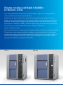
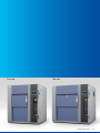
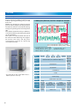
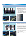
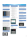
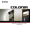
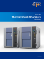
Air to Air
Thermal Shock Chambers
TSA Series
CAT.NO.E11138-Z1111
Energy savings and high reliability
in the new series
New series thermal shock chambers have been developed to improve our existing models, in
terms of reliability, but also in terms of efficiency.
Compared to the previous TSA series, the power consumption has been reduced of 35-50%.
Energy saving is achieved thanks to the Eco operation mode; the instrumentation automatically
adjusts pre-cooling and pre-heating periods and runs operations with just the necessary energy.
Improvements in chamber’s reliability. Particular emphasis was placed on removing unnecessary
loads and stresses from the refrigeration system, refrigerators themselves,
and the refrigeration circuit.
Various measures have been implemented to anticipate troubles and enhance chamber’s reliability.
Thermal stress on the specimen can differ according to its position; therefore we have further
minimized variations in the temperature attainment time that influences test results. Finally, we
are accurately responding to the needs of these days by adapting our safety designs to global
requirements, thanks to our experience of the market.
TSA–72
1
TSA–102
TSA–202
TSA–302
* Equipped with options.
2
Characteristics
Maximum 50% reduction in power consumption with Eco operation
mode and new refrigerator control system
● Power
consumption amount comparison example
(Power consumption amount per cycle by comparing ESPEC chambers)
–43%
TSA−72ES−A
The new series incorporates an algorithm
that calculates the minimum operation
time for pre-cooling and pre-heating by
constantly measuring the amount of heat
required for these processes in eco
operation mode. This feature can further
reduce power consumption and remove
the inaccuracies and hassles caused by
adjustments based on preliminar y
experiments. Tests operation achieves both
energy savings and reproducibility/
reliability.
Previous model
–40%
TSA−102ES−W
–35%
TSA−202ES−W
0
5.0
10.0
15.0
Power consumption
amount (kWh)
15.0
Power consumption
amount (kWh)
–50%
TSA−72EH−W
Previous model
0
5.0
10.0
Test conditions (Two-zone)
High-temp. exposure : +125°C
Low-temp. exposure : –40°C
Specimen: Plastic molded ICs: 5 kg (72, 102)
10 kg (202)
● Temperature
Parallel refrigerator control
system for energy-saving
control (Patent pending)
Exposure time :
30 min.
Temperature recovery time : Within 5 min.
changes under Eco operation (example)
Eco operation
Normal operation
Cold chamber
Hot chamber
Operation setup
Stop operation Pre-heating operation
High-temp.
exposure
Pre-heating
Stop operation operation
High-temp.
exposure
Test area
temperature
(option: power meter)
(compared to previous chamber)
180
Test area temperature
140
80
60
40
Power (kW)
3
emperature (°C)
120
100
To optimize further the power consumption,
the chamber features a parallel control
system that connects two small refrigerators
in parallel to the secondary side of the
refrigeration circuit. The chamber can
operate at the optimal refrigeration capacity
based on the controlled temperature, by
switching operation bet ween t wo
refrigerators simultaneously or a single
refrigerator. At stable low-temperature
exposures, power consumption is also
reduced by limiting refrigeration capacity
with an electronic expansion valve.
Measuring used power
Low-temp.
Low-temp.
exposure
exposure
Stop operation Pre-cooling operation
Stop operation Pre-cooling operation
● Parallel refrigerator control system power during Eco operation
160
Automatic setting of
pre-cooling and pre-heating
in energy saving, Eco
operation mode (Patent pending)
A wattmeter is provided as an option to
measure the power consumed. It is also
possible to halt a test by setting the stop
time. This function is useful for saving
energy.
Characteristics
Further reductions in power consumption with 500-hour continuous tests
1000 cycles continuous
operation
EH Type
Test start
1000 cycles
24h
24h
24h
Defrost 1h
24h
Test time
20-hour reduction
(Defrost 1 hour x 20 times)
Power
consumption amount
272 kWh reduction
1000 cycles
Consumed power amount to defrost once : 13.6 kWh
Consumed power amount to defrost (20 times) : 272 kWh
(option: defrost-free operation)
Defrost-free operation is provided as an
option so 500-hour continuous operation
can be performed without interruption (if
test conditions are set for 15-minute
exposure).
Defrost 1h
Defrost 1h
Defrost 20 times
Defrost 1h
Until now testing was interrupted for
defrosting when necessary, but ESPEC
has developed a unique structure that stops
frost formation under low temperatures
by preventing the penetration of outside
air (defrost-free operation [patent 3514735]).
Defrosting during cycle tests is then
unnecessary, thus reducing defrosting time
and the power consumed for this
operation.
cycles (500-hour) test time comparison example
Defrost operation
(option: defrost-free operation)
● 1000
Defrost-free operation
Minimizing defrosting burden
with defrost-free operation
Test conditions (Two-zone, No test halt)
High-temp. exposure : +150°C 15 min.
Low-temp. exposure : −65°C 15 min.
Outside conditions : +23°C/60% rh
Cooling water temp. : +25°C
Specimen : No specimen
Vertical sliding door
Combination with the
ESPEC’s evaluation system
The ESPEC’s Conductor Resistance
Evaluation System (sold separately) can
continuously measure the minute resistance
in solder joints and the conductive sections
of connectors in low temperature and high
temperature thermal cycle environments.
It can be used connected to the thermal
shock chamber.
EH Type
1000 cycles
Cable port ø50 mm
24h
24h
24h
Defrost 1h
Defrost 1h
Defrost 1h
Defrost 20 times
Defrost 1h
The chamber is equipped with a ø50 mm
cable port so cables with bulky terminal
connectors and plugs can be easily
connected. A flat cable port is also available
as an option.
cycles (500-hour) test time comparison example
Test start
Defrost operation
Equipped with a round cable port
● 1000
Vertically sliding door
24h
Test time
20-hour reduction
Defrost-free operation
Equipped with a vertical sliding structure,
the door does not disrupt when inserting
and removing specimens or when
connecting cables to a specimen. The door
has been lightened so that it can be easily
opened and closed.
(Defrost 1 hour x 20 times)
Power
consumption amount
272 kWh reduction
1000 cycles
Power consumed amount to defrost once : 13.6 kWh
Power consumed amount to defrost (20 times) : 272 kWh
Test conditions (Two-zone, No test halt)
High-temp. exposure : +150°C 15 min.
Low-temp. exposure : −65°C 15 min.
Outside conditions : +23°C/60% rh
Cooling water temp. : +25°C
Specimen : No specimen
Conductor Resistance Evaluation System connection (example)
4
Characteristics
The pursuit of high performance, high accuracy, and ease of use.
Highly accurate temperature
recovery
● Recovery rate & temperature uniformity
TSA−202ES−W measurement example
+123°C
±1.0°C
or lower
4.4 min.
–38°C
Test conditions
High-temp. exposure: +125°C, 30 min.
Pre-heating temperature: +145°C
Low-temp. exposure: –40°C, 30 min.
Pre-cooling temperature:– 55°C
7.3 min.
±1.5°C or lower
Dampers with integrated rectifying
function minimize variation in exposure
conditions due to specimen position within
the test area. This reduces the overall test
time and shortens temperature recovery
time, especially during low-temperature
exposure. The uniformity in test conditions
brought by this innovation also contributes
to improved test reproducibility and
reliability.
Even more reliable tests
(option: specimen temperature control*)
Specimen: Printed circuit boards 150 pcs.
Measuring points: 10
A single temperature sensor is attached
to the specimen in the test area and the
chamber is controlled by this temperature
measurement.
Even more accurate tests can be run by
controlling the chamber with the specimen
temperature because the air temperature
and the temperature inside the specimen
are different when attaining the temperature
setting. The chamber is controlled so that
the specimen temperature achieves the
temperature setting even quicker and more
accurately.
* Cannot be combined with Eco operation
mode.
Specimen temperature
monitoring
(option: specimen temperature monitor
with trigger function)
Test area
5
Two temperature sensors are attached to
the specimen in the test area to measure
the specimen's temperature.
This option features a trigger function that
switches to the exposure test after the two
temperatures reach the temperature setting,
so even more precise thermal tests can be
run.
* Cannot be combined with Eco operation
mode.
Characteristics
Improved reliability. Use our chambers safely and with peace of mind for
many years to come.
Global safety design
ELV
EV
Drainage
Evaporator
Cascade
condenser
Inter. INJ
To reduce thermal stress on the refrigerators
and prevent corrosion in the circuit, the
material and thickness of piping has been
changed and this prevents refrigerant leaks.
Th rough other cou ntless det ailed
improvements, the reliability of the
refrigeration circuit has been increased
and it can be used safely for many years
to come.
● Refrigeration circuit
(Parallel refrigeration system: patent pending)
Inter. INJ
The newly developed
refrigeration system improves
the refrigeration circuit reliability
Condenser
Water
Accumulator
Compressor
Accumulator
Compressor
Compressor
We deliver chambers that conform to
international safety standards.
Our chambers conform to ISO risk
assessment as well as global safety design
electrical safety standards such as CE
marking and EMC directive.
· ISO 12100: 2010
· ISO 60204-1
· IEC 610000-6
*EN standardization is standardized
by the European Union
6
Instrumentation
Color LCD interactive touch-screen system
Operation and settings simplified by the
use of a touch-screen LCD display
(instructions displayed on-screen). At-aglance confirmation of test patterns, test
area temperatures, temperature cycles,
upstream / downstream control, and trend
graphs display.
Enhanced test halt preset function
(Patent pending)
It is now possible to program tests to halt
after cycle or exposure completion. Six
cycle counters are also built-in to the
instrumentation so a test halt preset can
be programmed for each counter. The
function can be used to multiple ends such
as removing specimens to the chamber.
● Test
settings
● Test
detail monitor
Test continuity selection function
When the test is halted, select to resume
the test from the point where it was halted
or to start the test from the beginning.
● Halt
preset function
● Service
guide
Setting
Interactive key input by touch panel
Display
TFT Color LCD (10.4–inch)
Temperature
control
function
Setting
resolution
Temperature controls are PID control
Temperature: 1°C
Time: 1 min.
(Remaining time display is 1 sec.)
Input
Thermocouple type T (copper/copper-nickel)
Setting range
Time: 0 to 99 hours 59 minutes
Test cycle: 1 to 9999 cycles
Test patterns
RAM (freely register):40 patterns max.
(Registration possible)
ROM (built-in fixed): 20 standard test patterns
Registered
Auxiliary
functions
• Timer preset
• Test continuity selection
• Overheat/overcool
protection
• Up-stream/down-stream
sensor selection
• Stable time control
• Exposure time reduction
• Eco operation
• Power failure recovery
operation selection
• Automatic defrost
• Temperature recovery
time setting
• Pre-conditioning/
posttreatment
• Dry operation
● Alarm
7
Test area: exposure temp.
Hot chamber: pre-heating temp.
Cold chamber: pre-cooling/defrosting temp.
• Program memory
• Automatic power
shut-off
• Programmed time
display
• Cycle counter
• Test halt preset
• Completion mode
selection
• Trend graph
• Alarm history display
• Sensor calibration
• RS–485 communication
• Accumulated time
TEST STANDARD AND COMPATIBLE MODELS
Exposure temperature
Test standard
High temp.
Ambient
temp.
A +10
+85°C
0
+15
C +150°C
0
+15
D +200°C
0
Temperature
Ambient recovery time
Low temp. High/low temp.
temp.
Number of
test cycles
Model*1
Test starting
point
EL type ES type EH type
—
–
55°C 0
–10
B +15
+125°C
0
MIL–STD–883H
(Method No. 1010.8)
Exposure time
—
—
10 min. or longer
—
–
65°C 0
–10
E +15
+300°C
0
Worst case
specimen
Low temp.
Minimum
temp.
or
10
Within
High temp.
15 min.
F +15
+175°C
0
+3
A +85°C
0
MIL–STD–202G
(Method No. 107G)
0
–55°C
–3
—
—
—
—
—
—
—
—
—
—
*2
*3
*2
*2
+3
B +125°C
0
Differs according to
specimen weight
—
+5
C +200°C
0 +10
+25°C
+5 –5
D +350°C
0
28 g or lower,
5 cycles
Up–stream
15 min. or 30 min.
Max
25 cycles
Within
Low temp.
50 cycles
28 g to 136 g, 30 min. 5 min.
5 min.
100
cycles
136 g to 1.36 kg, 60 min.
1.36 to 13.6 kg, 120 min.
13.6 to 136 kg, 240 min.
—
—
—
—
—
—
—
—
0
–
65°C –5
+5
E +500°C
0
+3
F +150°C
0
—
+70°C ±2
+85°C ±2
+100°C ±2
IEC 60068–2–14
+125°C ±2
(JIS C 60068–2–14)
+155°C ±2
+175°C ±2
+200°C ±2
—
–5°C ±3
3 hrs.
–10°C ±3
2 hrs.
–25°C ±3
1 hrs.
–40°C ±3
If not specified:
–55°C ±3
3 hrs.
–65°C ±3
JASO D 014–4
+65°C ±2
+70°C ±2
+80°C ±2
+85°C ±2
+90°C ±2
+100°C ±2
+110°C ±2
+120°C ±2
+125°C ±2
+130°C ±2
+140°C ±2
+150°C ±2
+155°C ±2
+160°C ±2
—
–20°C ±3
–40°C ±3
EIAJ ED–2531A
+60°C ±2
+65°C ±2
+70°C ±2
+75°C ±2
+80°C ±2
+85°C ±2
+90°C ±2
+95°C ±2
+100°C ±2
Ambient
temp.
20 min.
40 min.
60 min.
90 min.
0°C ±3
–5°C ±3
–10°C ±3
–15°C ±3
3 hrs.
–20°C ±3
2 hrs.
–25°C ±3
1 hrs.
–30°C ±3 If not specified:
–35°C ±3 3 hrs.
–40°C ±3
–45°C ±3
–50°C ±3
*2
—
Exposure If not
time
specified
within 10% 5 cycles
Low temp.
*2
*2
—
Exposure If not
time
specified
within 10% 5 cycles
Low temp.
*2
*2
2 to
3 min.
Exposure
5 or
time
10 cycles
within 10%
Low temp.
*2
*3
*1 The test results may not meet specifications depending on the quantity of specimens or the setting method.
*2 Some models cannot be used depending on test conditions. For further information, please contact ESPEC.
*3 Applicable when equipped with the ambient-temperature exposure option.
8
CHAMBER AND UTILITY REQUIREMENTS
EL type
Power supply
Model
42EL−A
ES type
72EL−A
102EL−A 202EL−W 302EL−W 72ES−A
Air-cooled
Water-cooled
EH type
72ES−W 102ES−W 202ES−W 72EH−W
Air-cooled
Water-cooled
Water-cooled
200 VAC
49 A
70 A
70 A
110 A
120 A
78 A
120 A
112 A
220 VAC
47 A
70 A
70 A
110 A
120 A
75 A
120 A
108 A
380/400/415 VAC
27 A
45 A
45 A
65 A
70 A
50 A
70 A
60 A
0.4 to 0.7 MPa (4 to 7 kgf/cm2)
Air
50 Hz
—
95700
—
59700
95700
95700
60 Hz
—
96100
—
64800
104600
96100
Cooling water supply
rate (at reference
water temp.+32°C)*1*2
—
4.6 m3 /h
—
3.1 m3 /h
Water pressure
—
0.2 to 0.5 MPa
(2 to 5 kgf/cm2)
—
Condensation
load (KJ/h)*1
Piping connection size
Outside dimensions
mm (inch)
0.2 to 0.5 MPa
(2 to 5 kgf/cm2)
32 A
W 1140
H 1900
D 1270
W 1310
H 1900
D 1470
*1 Maximum possible value during temperature recovery.
*2 Rate depends on the cleanliness of the heat exchanger.
9
4.6 m3 /h
W 1550
H 1900
D 1470
W 1550
H 1900
D 1770
W 1870
H 1900
D 1770
W 1310
H 1900
D 1470
W 1550
H 1900
D 1470
W 1550
H 1900
D 1770
W 1310
H 1900
D 1770
EL Type
Model
TSA–42EL–A
TSA–72EL–A
Cold chamber Hot chamber Test area
Temp. recovery
Performance*1
System
High temp. exposure range*2
TSA–302EL–W
–65 to 0°C (–85 to +32°F)
Temp. fluctuation*3
±0.5°C (±0.9°F)
Pre-heat upper limit
+205°C (+401°F)
Temp. heat up time*4
Within 10 min.
Ambient temp. to +200°C (+392°F)
Within 15 min.
Within 70 min.
Ambient temp. to –70°C (–94°F)
Within 40 min.
Within 60 min.
Within 70 min.
Pre-cool lower limit
Temp. pull down time*4
–75°C (–103°F)
Within 40 min.
Two-zone: High temp. exposure: +125°C 30 min. Low temp. exposure: –40°C 30 min.
Power supply voltage: Rated voltage Sensor position: Upstream
Recovery conditions
Temp. recovery time*5
Specimen 3.5 kg
Specimen 6.5 kg
Specimen 7.5 kg
Specimen 16 kg
Specimen 17 kg
(Plastic molded ICs, 2.5 kg,
(Plastic molded ICs, 5 kg,
(Plastic molded ICs, 5 kg,
(Plastic molded ICs, 10 kg,
(Plastic molded ICs, 10 kg,
specimen basket/brackets 1 kg) specimen basket/brackets 1.5 kg) specimen basket/brackets 2.5 kg) specimen basket/brackets 6 kg) specimen basket/brackets 7 kg)
Within 15 min.
Within 5 min.
Within 10 min.
Cold-rolled rust proof treated steel plate (melamine resin coating)
Interior material
Stainless steel plate
Insulation
Glass wool, rigid polyurethane foam
Door
Manually operated sliding door with unlock button
Heater
Refrigeration unit
TSA–202EL–W
Ambient temp. +50 to +200°C (+122 to +392°F)
Low temp. exposure range
Exterior material
Construction
TSA–102EL–A
Two-zone test by means of damper switching
Stripped wire heater
Mechanical cascade refrigeration system
System
Air-cooled condenser
Hermetically sealed
rotary compressor
Compressor
Hermetically sealed scroll compressor
Expansion mechanism
Electronic expansion valve, other
High temp. side: R404A
Low temp. side: R508A
Refrigerant
Water-cooled condenser
High temp. side: R404A
Low temp. side: R23
Cooler
Plate fin cooler, cold accumulator
Air circulator
Sirocco fan
Damper driving unit
Air cylinder
Test area load resistance
30 kg (Equally distributed load)
50 kg (Equally distributed load)
240 x 460 x 370
410 x 460 x 370
650 x 460 x 370
650 x 460 x 670
970 x 460 x 670
Inside dimensions (W x H x D mm/in.)
(9.45 x 18.11 x 14.57) (16.14 x 18.11 x 14.57) (25.59 x 18.11 x 14.57) (25.59 x 18.11 x 26.38) (38.19 x 18.11 x 26.38)
1140 x 1900 x 1270
1310 x 1900 x 1470
1550 x 1900 x 1470
1550 x 1900 x 1770
1870 x 1900 x 1770
Outside dimensions (W x H x D mm/in.) *6
(44.88 x 74.80 x 50) (51.57 x 74.80 x 57.87) (61.02 x 74.80 x 57.87) (61.02 x 74.80 x 69.69) (73.62 x 74.80 x 69.69)
Weight
Approx. 730 kg
Approx. 900 kg
49 A
70 A
Allowable ambient conditions
Utility requirements
200 VAC 3ø 50/60 Hz
Power supply
Approx. 1050 kg
Approx. 1200 kg
Approx. 1420 kg
0 to 40°C (+32 to +104°F)
70 A
110 A
120 A
120 A
220 VAC 3ø 60 Hz
47 A
70 A
70 A
110 A
380/400/415 VAC 3ø 50 Hz
27 A
45 A
45 A
65 A
70 A
62 dB
65 dB
Noise level*7
65 dB
Air supply
0.4 to 0.7 MPa (4 to 7 kgf/cm2)
Cooling water supply pressure
Cooling water supply
rate*8
Operating cooling water temp. range
*1 Air-cooled: Ambient temperature of +23°C
Water-cooled: Ambient temperature of +10 to +30°C and a cooling water
temperature of +25°C
*2 If the high-temperature exposure range lower limit +60°C is required,
select the “ambient-temperature exposure” option
*3 Performance shown above conforms to IEC 60068-3-5: 2001
*4 Temperature heat-up/pull-down time are applicable only during independent
chamber operation
—
0.2 to 0.5 MPa (2 to 5 kgf/cm2)
—
4.6 m3 /h (ref. water temp.: +32°C)
—
+5 to +38°C (+41 to +100°F)
*5 Tolerance in temperature recovery time is based on IEC60068-2-1 and
IEC60068-2-2
*6 Excluding protrusions
*7 Noise level was measured in an anechoic room at a height of 1.2 m from the
floor and a distance of 1 m from the chamber front panel (ISO 1996-1:2003
A-weighted sound pressure level). Actual noise emissions may increase
because of surrounding reverberations in the place of installation, therefore use
caution in selecting a place of use.
*8 Rate depends on the cleanliness of the heat exchanger
10
ES Type
Model
TSA–72ES–A/W
Cold chamber Hot chamber Test area
Temp. recovery
Performance*1
System
TSA–102ES–W
High temp. exposure range
+60 to +200°C (+140 to +392°F)
Low temp. exposure range
–70 to 0°C (–94 to +32°F)
±0.5°C (±0.9°F)
Temp. fluctuation*2
Pre-heat upper limit
+205°C (+401°F)
Temp. heat up time*3
Ambient temp. to +200°C (+392°F) within 15 min.
Pre-cool lower limit
Temp. pull down time*3
Recovery conditions
–75°C (–103°F)
Ambient temp. to –75°C (–103°F)
Within 50 min.
Within 40 min.
Within 45 min.
· Three-zone
High-temp. exposure: · Three-zone
+150°C, 30 min.
High-temp. exposure: +150°C, 30 min.
Ambient-temperature exposure:
Ambient-temperature exposure: Ambient temperature, 5 min.
Ambient temperature, 10 min.
Low-temp. exposure: –65°C, 30 min.
Low-temp. exposure:
· Power supply voltage: Rated voltage
–65°C, 30 min.
· Sensor position: Upstream
· Power supply voltage: Rated voltage
· Sensor position: Upstream
· Specimen 6.5 kg
· Specimen 7.5 kg
· Specimen 26 kg
Plastic molded ICs: 5 kg
Plastic molded ICs: 5 kg
Plastic molded ICs: 20 kg
Specimen basket/brackets: 1.5 kg Specimen basket/brackets: 2.5 kg Specimen basket/brackets: 6 kg
Temp. recovery time*4
Within 5 min.
Exterior material
Stainless steel plate
Insulation
Glass wool/rigid polyurethane foam
Door
Manually operated sliding door with unlock button
Heater
Refrigeration unit
Within 10 min.
Cold rolled rust proof treated steel plate (melamine resin coating)
Interior material
Construction
TSA–202ES–W
Two-zone or three-zone test by means of damper switching
Stripped wire heater
Mechanical cascade refrigeration system
System
Air-cooled condenser or
water-cooled condenser
Compressor
Water-cooled condenser
Hermetically sealed scroll compressor
Expansion mechanism
Electronic expansion valve, other
Refrigerant
High temp. side: R404A Low temp. side: R23
Cooler
Plate fin cooler, cold accumulator
Air circulator
Sirocco fan
Damper driving unit
Air cylinder
Test area load resistance
Inside dimensions (W x H x D mm/in.)
30 kg (Equally distributed load)
410 x 460 x 370 (16.14 x 18.11 x 14.57)
50 kg (Equally distributed load)
650 x 460 x 370 (25.59 x 18.11 x 14.57)
650 x 460 x 670 (25.59 x 18.11 x 26.38)
Outside dimensions (W x H x D mm/in.) *5 1310 x 1900 x 1470 (51.57 x 74.80 x 57.87) 1550 x 1900 x 1470 (61.02 x 74.80 x 57.87) 1550 x 1900 x 1770 (61.02 x 74.80 x 69.69)
Weight
Approx. 1050 kg
Approx. 1150 kg
Utility requirements
Allowable ambient conditions
Power supply
200 VAC 3ø 50/60 Hz
78 A
120 A
220 VAC 3ø 60 Hz
75 A
120 A
380/400/415 VAC 3ø 50 Hz
50 A
70 A
65 dB or lower
Noise level*6
0.4 to 0.7 MPa (4 to 7 kgf/cm2)
Air supply
Cooling water supply pressure
Cooling water supply
rate*7
Operating cooling water temp. range
0.2 to 0.5 MPa (2 to 5 kgf/cm2) (water-cooled specification)
3.1
m3 /h
0.2 to 0.5 MPa (2 to 5 kgf/cm2)
(reference water temp: +32°C) (water-cooled specification) 4.6 m3 /h (reference water temp: +32°C)
+5 to +38°C (water-cooled specification)
*1 Ambient temperature of +23°C and a cooling water temperature of +25°C
*2 Performance shown above conforms to IEC 60068-3-5: 2001
*3 Temperature heat-up/pull-down time are applicable only during independent
chamber operation
*4 Tolerance in temperature recovery time based on IEC60068-2-1 and IEC60068-2-2
*5 Excluding protrusions
11
Approx. 1400 kg
0 to +40°C (+32 to +104°F)
*6 Noise level was measured in an anechoic room at a height of 1.2 m from the
floor and a distance of 1 m from the chamber front panel (ISO 1996-1:2003
A-weighted sound pressure level). Actual noise emissions may increase
because of surrounding reverberations in the place of installation, therefore
use caution in selecting a place of use.
*7 Rate depends on the cleanliness of the heat exchanger
EH Type
Two-zone or three-zone test by means of damper switching
Temp. recovery
Cold chamber Hot chamber Test area
TSA–72EH–W
System
Performance*1
Model
High temp. exposure range*2
+60 to +200°C (+140 to +392°F)
Low temp. exposure range
–70 to 0°C (–94 to +32°F)
±0.5°C (±0.9°F)
Temp. fluctuation*3
Pre-heat upper limit
+205°C (+401°F)
Temp. heat up time*4
Ambient temp. to +200°C (+392°F) within 15 min.
Pre-cool lower limit
Temp. pull down time*4
Recovery conditions
–77°C (–106.6°F)
Ambient temp. to –75°C (–103°F) within 50 min.
· Two-zone
High-temp. exposure: +150°C, 15 min.
Low-temp. exposure: –65°C, 15 min.
· Power supply voltage: Rated voltage
· Sensor position: Downstream
· Specimen 5 kg
Plastic molded ICs: 3.5 kg
Specimen basket/brackets: 1.5 kg
Temp. recovery time*5
Within 5 min.
Exterior material
Cold rolled rust proof treated steel plate (melamine resin coating)
Interior material
Stainless steel plate
Insulation
Glass wool/rigid polyurethane foam
Manually operated sliding door with unlock button
Heater
Refrigeration unit
Construction
Door
Stripped wire heater
Mechanical cascade refrigeration system
Water-cooled condenser
System
Compressor
Hermetically sealed scroll compressor
Expansion mechanism
Refrigerant
Electronic expansion valve, other
High temp. side: R404A Low temp. side: R23
Cooler
Plate fin cooler, cold accumulator
Air circulator
Sirocco fan
Damper driving unit
Air cylinder
Test area load resistance
30 kg (Equally distributed load)
Inside dimensions (W x H x D mm/in.)
410 x 460 x 370 (16.14 x 18.11 x 14.57)
Outside dimensions (W x H x D mm/in.) *6
1310 x 1900 x 1770 (51.57 x 74.80 x 69.68)
Weight
Approx. 1150 kg
Utility requirements
Allowable ambient conditions
Power supply
0 to +40°C (+32 to +104°F)
200 VAC 3ø 50/60 Hz
112 A
220 VAC 3ø 60 Hz
108 A
380/400/415 VAC 3ø 50 Hz
60 A
65 dB or lower
Noise level*7
0.4 to 0.7 MPa (4 to 7 kgf/cm2)
Air supply
0.2 to 0.5 MPa (2 to 5 kgf/cm2)
Cooling water supply pressure
Cooling water supply
rate*8
4.6 m3 /h (reference water temp: +32°C)
Operating cooling water temp. range
*1 Ambient temperature of +23°C and a cooling water temperature of +25°C
*2 During pre-heating, prevention operation for temperature heat-up may be worked.
*3 Performance shown above conforms to IEC 60068-3-5: 2001
*4 Temperature heat-up/pull-down time are applicable only during independent
chamber operation
*5 Tolerance in temperature recovery time based on IEC60068-2-1 and IEC60068-2-2
*6 Excluding protrusions
+5 to +38°C
*7 Noise level was measured in an anechoic room at a height of 1.2 m from the
floor and a distance of 1 m from the chamber front panel (ISO 1996-1:2003
A-weighted sound pressure level). Actual noise emissions may increase
because of surrounding reverberations in the place of installation, therefore
use caution in selecting a place of use.
*8 Rate depends on the cleanliness of the heat exchanger
12
SAFETY DEVICES
• Leakage breaker (200, 220V AC specifications)
MODEL
TSA –
• Circuit breaker (380, 400/415V AC CE specifications)
Condensation system
A : Air-cooled type
W : Water-cooled type
• Electrical compartment door switch
• Test area door switch
• Hot chamber overheat protection switch
Performance classification
EL
ES
EH
• Cold chamber overheat protection switch
• Hot chamber overheat protector (controller)
• Cold chamber overheat protector (controller)
Test area capacity
42 : 40L
72 : 70L
102 : 110L
202 : 200L
302 : 300L
• Air circulator overload relay
• Refrigerator high/low pressure switches
• Compressor built-in protector (except TSA–42EL)
• Compressor temperature switch
• Thermal relay for compressor (TSA–42EL only)
• Water suspension relay (water-cooled specification only)
• Air circulator thermal relay
ACCESSORIES
• Motor reverse prevention relay
• Specimen basket (18-8 Cr-Ni stainless steel/5 mesh metal basket)
• Air pressure switch
TSA–42
(W230 x H40 x D356 mm/load capacity 2.5 kg) ······················ 2
• Fuse
• Cooling tower interlock terminal (water-cooled specification only)
• Compressor circuit breaker
• Heater circuit breaker
• Test area overheat/overcool protector (controller)
• Test area overheat/overcool protector (option)
• Air purge valve
• Specimen power supply control terminal
TSA–72
(W400 x H40 x D356 mm/load capacity 5 kg) ························· 2
TSA–102
(W640 x H40 x D356 mm/load capacity 5 kg) ························· 2
TSA–202
(W640 x H40 x D656 mm/load capacity 17 kg) ······················· 2
TSA–302
(W960 x H40 x D656 mm/load capacity 17 kg) ······················· 2
FITTINGS
• Cable port ø50 mm (left side) ·················································· 1
• Specimen power supply control terminal ································ 1
• Time signals ············································································· 2
• Shelf brackets
(shelf attachment pitch 60 mm, adjustable in 7 levels) ···· 2 sets
• Cartridge fuse
DANGER
● Do not use explosive substances, flammable
substances, or substances that contain those
substances as a specimen under any circumstances.
Danger: Risk of explosion and fire.
● Do not put corrosive substances inside the test
area. If corrosive substances are generated from
the specimen, the life of the product's corrosion
resistance will decrease dramatically due, in
particular, to corrosion of stainless steel, resin,
and silicone.
● Do not use living organisms or items that exceed the
allowable heat load as a specimen.
CAUTION
13
Always read the user's manual before using the
product.
5A ···························································································· 2
10A (non-standard specification) · ·········································· 1
• Cable port rubber plug ····························································· 1
• Nipple (water-cooled specification only) ·································· 1
• Strainer (water-cooled specification only) ······························· 1
• Strainer element (water-cooled specification only) ················· 1
• User’s manual · ········································································· 1
DIMENSIONS
(Unit: mm)
TSA−72EL · 72ES
580
410
495
880
550
135
370
1900
460
1470
560
235
1310
TSA−202EL · 202ES
820
650
495
850
135
880
670
1900
460
1770
560
235
1550
14
1000 cycles
Consumed power amount to defrost once : 13.6 kWh
Consumed power amount to defrost (20 times) : 272 kWh
Test conditions (Two-zone, No test halt)
High-temp. exposure : +150°C 15 min.
Low-temp. exposure : −65°C 15 min.
Outside conditions : +23°C/60% rh
Cooling water temp. : +25°C
Specimen : No specimen
OPTIONS
Defrost-free operation
● 1000
cycles (500-hour) test time comparison example
EH Type
Test start
1000 cycles
24h
24h
24h
Defrost 1h
Defrost 1h
Defrost 1h
Defrost 1h
Defrost operation
Defrost 20 times
24h
Test time
20-hour reduction
Defrost-free operation
For two-zone tests, enables continuous tests
without requiring defrosting for up to 500
hours max.
ESPEC has developed a unique structure
(patent: 3514735) that prevents the penetration
of outside air and uses recirculated air during
testing to stop frosting on the low-temperature
side.
This enables continuous tests up to 500 hours,
so around 20 defrost cycles during this period
can be eliminated.
This option can reduce both the test time in
the amount of the defrosting time (approx.
60 minutes each time) and the power
consumption required for def rosting
(13.6 kWh each time).
(Defrost 1 hour x 20 times)
Power
consumption amount
272 kWh reduction
1000 cycles
Power consumed amount to defrost once : 13.6 kWh
Power consumed amount to defrost (20 times) : 272 kWh
Test conditions (Two-zone, No test halt)
High-temp. exposure : +150°C 15 min.
Low-temp. exposure : −65°C 15 min.
Outside conditions : +23°C/60% rh
Model
Number of
cycles
* The TSA−42EL−A, 72EL−A and 102EL−A have a
300-mm protrusion on the top.
Temp.
recovery
time
15
TSATSATSA-302EL TSA-72EH
102EL, ES 202EL, ES
Maximum
1000 cycles
Maximum 500 cycles (Maximum 500-hour)
(Maximum
500-hour)
TSA-42EL
TSA72EL, ES
High-temp.
exposure/
time
Low-temp.
exposure/
time
Outside
conditions
Cooling
water temp.
Power
supply
voltage
Sensor
position
Specimen
Cooling water temp. : +25°C
Specimen : No specimen
+125°C/30 min.
+150°C/
15 min.
−40°C/30 min.
−65°C/
15 min.
+23°C/60% rh
+25°C
Rated voltage
Downstream of specimen
1.5 kg
Plastic molded
ICs 1.0 kg
Specimen
basket/shelf
brackets 0.5 kg
( ) (
Within
15 min.
5.0 kg
Plastic molded ICs 3.5 kg
Specimen basket/
shelf brackets 1.5 kg
10.0 kg
Plastic molded ICs 7 kg
Specimen basket/
shelf brackets 3 kg
) (
Within 5 min.
Within
10 min.
)
5.0 kg
Plastic molded
ICs 3.5 kg
Specimen
basket/shelf
brackets 1.5 kg
( )
Within
5 min.
OPTIONS
Specimen temperature control
● Measurement
A sensor is attached to the specimen to control
the chamber based on the specimen temperature.
The specimen temperature reaches and maintains
the temperature setting as fast and accurately as
possible.
(Cannot be combined with Eco operation mode.)
example TSA-72ES-A
200
150
Temperature (℃)
100
Specimen temp.
50
0
Upstream
sensor temp.
−50
● −100
Measurement
example TSA-72ES-A
200180 190 200 210 220 230 240 250 260 270 280 290 300 310 320
Temperature (℃)
Test conditions
150
High
temp. exposure +150℃ 30 min.
Ambient temp. exposure
5 min.
Low
temp. exposure −65℃ 30 min.
100
· Number of measuring points: 1
· Location: Chamber front, left-side panel
· Accessory: Thermocouple type T (copper,
copper-nickel) x1*
* 2 when simultaneously equipped with a
recorder
Specimen
Plastic molded ICs (3.5 kg)
Specimen baskets 2nd and 6th level from top
Control points
28-pin QFP (quad flat package) with
sensor installed at center of 6th level
Specimen temp.
50
0
Upstream
sensor temp.
−50
● Measurement
example
−100
No. of specimen temperature input terminal: 2
180
200 190 200 210 220 230 240 250 260 270 280 290 300 310 320
Temperature (℃)
Test conditions
150
High temp. exposure
+150℃ 30 min.
Specimen
Plastic molded ICs (3.5 kg)
Specimen
Start
Ambient temp.temp.
exposure
5 min.of exposure
Specimen baskets 2nd and 6th level from top
(1)
100exposure −65℃ 30 min.
time count
Low temp.
Control points
28-pin QFP (quad flat package) with
sensor installed at center of 6th level
50
Specimen
temp.
(2)
Specimen temperature
monitoring
with trigger
function
Start of exposure
0
time count
−50
● Measurement
−100
240
200
Temperature (℃)
150
100
250
example
260
No.270
of specimen
temperature
input
terminal:
2
280
290
300
310
Time (min.)
Specimen
temp. (1)
50
Start of exposure
time count
Specimen
temp. (2)
0
Start of exposure
time count
−50
−100
240
250
260
270
280
Time (min.)
290
300
310
Two sensors are attached to the specimen and
the temperature of the specimen displayed
on the instrumentation is monitored. The
option has a trigger function that switches to
the exposure test after the specimen
temperatures reach the temperature setting,
so even more precise tests can be run. It can
also record the temperatures of the specimen
and the test area when connected to a
temperature recorder.
(Cannot be combined with Eco operation
mode.)
· Number of measuring points: 2
· Location: Chamber front, left-side panel
· A ccessor y: T her mocouple t y pe T
(copper, copper-nickel) x2*
* 4 when simultaneously equipped with a
recorder
16
OPTIONS
Dual communication logger
Connect to a company network and the chamber status
can be monitored on PCs and data can also be
managed.
Chamber failures information can be sent to PCs and
cellular telephones via emails.
RS-485
LAN
Dual
communication
logger
Number of connected units
• 1 unit
Temperature
(Thermo-couple)
Functions
• Monitoring function
• Data management function
• Communication function
Monitoring function
Model
Monitor details
Analog input
Monitor screen
Data management
functions
Save data
· Operation state
· Exposure state
· Running cycle
· Setting cycle
· Test area temperature (Hot chamber,
cold chamber, specimen temp.)
Pattern manager
· Test area display temperature
Administration PC
· Remaining step time
· Number of alarms
· Alarm number 1, 2
· Trend graph
USB
Thermocouple, measured temperature resistance, voltage, contact, other temperature/humidity input
Interface
converter
Monitoring one chamber on one browser screen
Save data as binary data on a CFRS-485
card in the chamber
RS-485
From 1 sec. (display update interval asnd auto save interval)
File creation
interval
· Auto save interval
· Memory time up (select from hour, day, week, month)
Display saved data
Error notification
PC
TMS
Save interval
Download data
17
Intranet (company LAN)
Mail server
16 max.
Trend display, digital display with dedicated software, convert to Excel data, etc.
Download saved data via the network
· Send by email
· Change the logger display color
OPTIONS
Ambient-temperature exposure (EL type only)
Paperless recorder
Recorder wiring
Enables th ree-zone tests by adding a
damper mechanism and an air circulator.
· High temp. exposure range: +60 to 200°C
Records the temperature of each section such as
the temperature inside the chamber.
PL1S: Number of inputs: 1 (5 OFF*)
Scan interval: 1 sec.
PL3S: Number of inputs: 3 (3 OFF*)
Scan interval: 1 sec.
PL3L: Number of inputs: 3 (3 OFF*)
Scan interval: 5 sec.
PL4S: Number of inputs: 4 (2 OFF*)
Scan interval: 1 sec.
PL4L: Number of inputs: 4 (2 OFF*)
Scan interval: 5 sec.
PL5S: Number of inputs: 5 (1 OFF*)
Scan interval: 1 sec.
PL5L: Number of inputs: 5 (1 OFF*)
Scan interval: 5 sec.
· Temperature range: –100 to +220°C
· External memory
CF memory card port
(Includes a 256 MB CF card)
USB memory port
· Languages: English/Japanese, can be changed
* Channels can be turned ON
Preparation of a power cable, temperature
sensor, and conductor grounding wire for
additional installation in the future.
Recorder terminal
Used to output the temperature within test
area, hot chamber, and cold chamber.
Thermocouple
At t ached to specimens to measu re
specimen temperature.
· 2, 4, 6m
·T
hermocouple type T (Copper, copper-nickel)
Additional preventive measures can be
taken for excessive temperature rise in the
cha mber, i n add it ion to t he st a nd a rd
equipped overheat protector.
External alarm terminal
If the safety device of the chamber is
activated, the external alarm terminal will
notify it to a remote point.
Emergency stop pushbutton
Stops the chamber immediately.
Status indicator light
To check the state of the chamber from
distant locations.
Total cycle counter
Exposure signal output
A signal is output via a contact switch when
test area temperature is within the userselected range. This signal can be used to
c o nt r ol p e r i p h e r a l i n s t r u m e nt s , l i ke
applying a voltage to specimens only during
high temperature exposure, or monitoring
test operation f rom a remote point.
Preparation of a power cable, temperature
sensor, and conductor grounding wire for
additional installation in the future.
Additional overheat protectors
Indicates cycle counts.
· With reset function
· Display range: 1 to 99999999
Temperature recorder (digital display)
RK–61 1 pen
RK–63 3 pens
RK–64 6 dots
· Temperature range: –100 to +220°C
· Effective recording chart width 100 mm
Built-in air compressor
Select when there is no air supply source.
Power meter
Accumulates the amount of power the chamber uses.
18
OPTIONS
Automatic door
Specimen basket/shelf brackets
Power cable
Automatic sliding door (vertical) operated
by single-touch button. Equipped with 2
safety mechanisms: a photoelectric sensor,
and a touch sensor. A door stop switch is
also set.
* I f you also need the emergency stop
switch, please contact us.
Equivalent to standard accessory.
· Material: stainless steel (5 mesh)
5 m, 10 m
* T he cha mber does not come w it h a
power cable.
Heavy-duty shelf
Use to hold heavy specimens exceeding
the load capacity of the standard specimen
basket.
· Load capacity: 30 kg
Chamber dew tray
Prevents water leaks from the chamber
onto the floor.
* T he use of casters is recommended to
facilitate operation.
Additional cable port
Provided in addition / replacement of the
standard cable port (left side)
· φ50 mm round
Anchoring fixtures
Used to bolt the chamber to the floor.
Interface
· Computer interface: GPIB
· Serial interface: RS–232C
* Select one, instead of standard RS–485
Flat cable port
Provided in addition / replacement of the
standard cable port (left side).
· 25 x 100 mm slot
Communication cable
· RS-485 cable: 5, 10 m
· GPIB: 2, 4 m
· RS-232C: 1.5, 3, 5 m
Cable port rubber plug
Plug socket
Prevents air leakage from the cable port.
· φ50 mm for round port
· For flat cables
To supply power to external equipment
· 2 plug sockets
· Rated capacity 100 VAC 3 A
(Total capacity)
Caster
Installed for mobility.
· 6 casters (4 for TSA–42EL)
· 4 levelling feet
19
Thermal Shock Chamber Series
Air to Air Thermal Shock Chamber TSE
A compact thermal shock chamber to handle thermal
shock testing on small and limited volume specimens. It
supports standardized testing with no auxiliary cooling
and a two-zone (+150°C and –65°C) upstream air
temperature recovery time within 5 minutes. The TSE
model provides the same performance as ESPEC’s large
thermal shock chambers in a compact design.
Model
TSE–11
Temp. range
High temp. side:
+60 to +200°C
Low temp. side:
–65 to 0°C
Inside dimensions (mm)
W320 x H148 x D230
Air to Air Thermal Shock Chamber TSD
A two-zone thermal shock chamber that complies with
Japanese and global test standards such as MIL-STD-883
and JIS C 0025.
The TSD model can perform accurate testing by monitoring
the specimen temperature and starting the exposure time
count once it has reached the preset temperature or it can
immediately proceed to the next step in the sequence. The
temperature recovery time between +150°C and –60°C
is just 15 minutes, which reduces the total test duration.
Model
TSD–100
Temp. range
Inside dimensions (mm)
High temp. side:
+60 to +200°C
Low temp. side:
–65 to 0°C
W710 x H345 x D410
Liquid to Liquid Thermal Shock Chamber TSB
The liquid to liquid thermal shock chamber is designed to
apply higher stress to specimens.
It has also greatly reduced required minimum installation
space. The highly airtight test areas and numerous new
mechanisms reduce brine consumption, thus greatly
reducing running costs.
It features easy operation thanks to the color LCD
interactive touch-screen system.
Model
TSB–21
TSB–51
Temp. range
High temp. chamber:
+70 to +200°C
Low temp. chamber:
–65 to 0°C
Specimen basket
dimensions (mm)
W120 x H150 x D120
W150 x H150 x D200
20
Custom-made Equipment
Thermal Shock Chamber 300°C specification
Chambers that achieve high-temperature exposure of 300°C in thermal shock testing to find heat resistance at high temperatures.
Temp. recovery performance Temp. range
Model
TSA–72ES (+300°C specification)
TSD-100 (+300°C specification)
High temp. side
Low temp. side
High-temp.
exposure/time
Ambient-temp.
exposure/time
Low-temp.
exposure/time
–70 to 0°C
–65 to 0°C
+300°C/30 min.
+270°C/40 min.
Temperature
recovery time
Test area
dimensions (mm)
+300°C/30 min.
-
Ambient temp./5 min.
–65°C/30 min.
–40°C/40 min.
Sensor position
Specimen
TSE-11 (+300°C specification)
+60 to +300°C
–45°C/30 min.
Upstream of specimen
Plastic molded ICs: 5 kg
Plastic molded ICs: 5 kg
Plastic molded ICs: 1 kg
Within 20 min.
Within 5 min.
Within 10 min.
W410 x H460 x D370
W710 x H345 x D410
W320 x H148 x D230
* Supported TSA series models: TSA-72ES, TSA-102ES, TSA-72EH
Large capacity Thermal Shock Chamber
TSA–1650H
TSA–2600H
These chambers can be used to test large products such
as large parts used in automobiles, large flat panel displays
that continue increasing in size, and solar cell modules.
These chambers can also test a large volume of specimens
at a single time in such fields as quality inspections in
manufacturing processes.
Model
TSA–1050H
TSA–1650H
Performance
Temp. recovery performance Test area
System
21
• Two types of air direction: vertical and horizontal
• Features Eco operation mode
TSA–2600H
TSA–3600H
Two- or three-zone by means of damper switching
High temp.
exposure
+60 to +180°C
Low temp. exposure
Recovery
conditions
–60 to –10°C
• Two-zone: High-temperature exposure: +150°C, 60 min.
Low-temperature exposure: –50°C, 60 min.
• Sensor position:Upstream of specimen
Temp. recovery
time
Within 10 min.
Test area dimensions (mm)
W1500 x H700 x D1000
W1500 x H1100 x D1000
W1200 x H1200 x D1800
External dimensions (mm)
W2620 x H1785 x D2862
W2620 x H2210 x D3184
W4370 x H2290 x D2500 W4370 x H2590 x D2700
W1200 x H1500 x D2000
http://www.espec.co.jp/english
Head Office
3-5-6, Tenjinbashi, Kita-ku, Osaka 530-8550, Japan
Tel : 81-6-6358-4741
Fax : 81-6-6358-5500
ESPEC NORTH AMERICA, INC.
Tel : 1-616-896-6100 Fax : 1-616-896-6150
ESPEC EUROPE GmbH
Tel : 49-89-1893-9630 Fax : 49-89-1893-96379
ESPEC (CHINA) LIMITED
Tel : 852-2620-0830
Fax : 852-2620-0788
ESPEC ENVIRONMENTAL EQUIPMENT (SHANGHAI) CO., LTD.
Head Office
Tel : 86-21-51036677 Fax : 86-21-63372237
BEIJING Branch
Tel : 86-10-64627025 Fax : 86-10-64627036
TIANJIN Branch
Tel : 86-22-26210366 Fax : 86-22-26282186
GUANGZHOU Branch
Tel : 86-20-83317826 Fax : 86-20-83317825
SHENZHEN Branch
Tel : 86-755-83674422 Fax : 86-755-83674228
SUZHOU Branch
Tel : 86-512-68028890 Fax : 86-512-68028860
ESPEC TEST TECHNOLOGY (SHANGHAI) CO., LTD.
Tel : 86-21-68798008 Fax : 86-21-68798088
ESPEC SOUTH EAST ASIA SDN.BHD.
Tel : 60-3-8945-1377 Fax : 60-3-8945-1287
Quality Management System Assessed
and Registered
ESPEC CORP. has been assessed by and
registered in the Quality Management System
based on the International Standard ISO
9001:2008 (JIS Q 9001:2008) through the
Japanese Standards Association (JSA).
*Registration : ESPEC CORP.
(Overseas subsidiaries not included)
●
IT11E23C02 (The contents of this catalog is as of November, 2011.)
●
Environmental Management System Assessed
and Registered
ESPEC CORP.
Specifications are subject to change without notice due to design improvements.
Corporate names and trade names mentioned in this catalog are trademarks or registered trademarks.