1
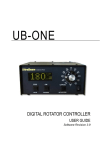
SOFTSTART USER'S MANUAL
ZJR1 SERIES
Foreword
Thank you for your purchase of ZJR1 series of motor soft starter produced by
Ziri Electrical Technology Co.,Ltd. (hereinafter referred to as ZIRI Company).
This manual introduces the installation, operation, function setting, trouble
shooting and etc. of ZJR1 motor soft starter.
Incorrect installation or use may result in damage or other accidents.
Do read all instructions in detail before installing, and follow this manual
strictly during installing, wiring and operating.
Please keep this manual handy for quick reference in the future.
If there are any doubts or questions, please contact the Technical Service
Center of ZIRI Company.
Table of Contents
Chapter 1 Introduction to the Product.............................................1
1.1 Safety Instructions....................................................1
1.2 Product Inspection upon Arrival..................................2
1.3 Demonstration of the Specifications Label and Model...2
1.4 Outline of the Product............................................... 3
1.5 Models and Specifications......................................... 4
1.6 Technical Indications.................................................5
Chapter 2 Installation and Wiring...................................................6
2.1 Operating Conditions............................................... .6
2.2 Installation............................................................... 6
2.3 Wiring................................................................. 7-12
2.4 Selection of Peripheral Appliances............................13
Chapter 3 Operation Panel and Display....................................... 14
3.1 Operation Panel Instructions.................................... 14
3.2 Panel Operation................................................. 14-15
3.3 Panel Display Instructions........................................16
Chapter 4 Operation...................................................................17
4.1 Inspection before Operation.....................................17
4.2 Operation...............................................................17
Chapter 5 Description of Function Parameters............................. 18
5.1 Schedule of Function Parameters.............................18
5.2 Detailed Description of Function Parameters.........19-26
Chapter 6 Trouble Protection & Treatment.................................... 27
6.1 Schedule of Protection Operating..............................27
6.2 Trouble Diagnosis and Troubleshooting.....................28
Chapter 7 Structure and Sizes................................................29-30
Chapter 8 Quality Warranty..........................................................31
Appendix....................................................................................32
Chapter 1 Introduction to Product
Chapter 1
Introduction to Product
The installation and wiring of motor soft starter should be
operated only by professional technicians who should read this
manual in detail before installing and wiring.
Do not perform wiring while the motor soft starter is POWER
ON. Be sure to perform this step only after the power is
disconnected. Otherwise, there is the danger of electric shock.
Be sure the motor chosen should be matched with the motor
soft starter. Do follow this manual while perform installing and
wiring.
While wiring, the three-phase input power supply should be
connected to the terminals R, S and T. The output wire of the motor
should be connected to the terminals U, V and W. Otherwise, it may
cause severe damage to the motor soft starter.
Do not install any capacitor between the output terminals U, V
and W and the motor. Otherwise, it may cause damage to the motor
soft starter.
The electronic elements inside the motor soft starter are very
sensitive to static. Do not touch the appliances on the circuit board
by hand before anti-static measures are taken.
The ground terminal ( G) should be properly, solidly and
separately grounded .
Once the motor soft starter is installed, please cover pigtails
in the input and output ports with insulated sheath or tape.
When the motor soft starter is under remote control, do lock
the keyboard control to avoid accidence due to error operation.
Do cut off the power supply when the motor starter is in
maintenance to guarantee safety.
1.2 Inspection upon Arrival
This product is guaranteed a high level of quality with strict outgoing
inspection, crushproof and shockproof packaging. But there is the
possibility of damage in transit by carelessness. So it is necessary to
unpack the package upon receipt of the product and perform the following
steps:
Check the motor soft starter whether there is any damage caused during
transit.
Check the specifications label of the motor soft starter and make sure it
matches the product part number you ve ordered.
Check whether the items in the package are in readiness or not, which
include 1 motor soft starter, 1 user manual and 1 conformity certificate.
In case there is any problem with the above-mentioned contents, damage or
deficiency, please contact your dealer or Ziri Company immediately.
1.3 Demonstration of the Specifications Label and Model
1.3.1 Demonstration of the Specifications Label
Name of Product
Model
Power
Input Power Supply
Rated Electric Current
Production Ordinal
1.3.2 Demonstration of the Model
Adaptive
Motor Power:
Indicated Voltage
Design Serial Number
Motor Soft Starter
Biz Code
Chapter 1 Introduction to Product
1.4 Outline of the Product
Connect to the bypass contactor
(L21, L22, L23)
1.5 Models and Specifications
Input Terminals of Power
Supply (R, S, T)
Nameplate
Operation Panel
Base
Circuit Board Cabinet
Control Terminal
Connect to the motor
(U, V, W)
Connect to the bypass contactor
(L21, L22, L23)
Circuit Board Cabinet
Base
Connect to the motor
(U, V, W)
Chapter 1 Introduction to Product
Input Terminals of Power
Supply (R, S, T)
Operation Panel
Control Terminal
Schedule of Models & Specifications
Product Model
Max Adaptive
Motor
Power(KW)
Input Voltage Rated Current Weight of
(V)
(A)
Type Z Kg
Chapter 1 Introduction to Product
1.6 Technical Indications
Item
Chapter 2
Item Description
Input
Input Voltage Three-phase 380V-15%
Power
50/60Hz
Supply Frequency
415+10%
Adaptive Motor
Squirrel-cage three-phase asynchronous motor
Starting Times
It is recommended not to exceed 20 times per hour
Control Modes
1) Operation panel control; 2) Operation panel + external
control; 3) External control; 4) External control + COM
control; 5) Operation panel + external + COM control; 6)
Operation panel + COM control; 7) COM control; 8) No start
or stop operation.
Start Modes
Stop Modes
Protective
Functions
Place to be
used
Ambient
Altitude
Installation and Wiring
1) Current-limiting start; 2) Voltage ramp start; 3) Kick
start + current-limiting start; 4) Kick start + voltage
ramp start; 5) Current ramp start; 6) Voltage currentlimiting double closed-loop start.
1) Soft stop; 2) Free stop.
1) Open loop protection for external instantaneous stop terminals; 2)
Over-heat protection for soft starter; 3) Protection for too long starting
time; 4) Input open phase protection; 5) Output open-phase protection;
6) Unbalanced three-phase protection; 7) starting overcurrent
protection; 8) Running overload protection; 9) Undervoltage protection
for power voltage; 10) Overvoltage protection for power voltage; 11)
Protection for fault parameter setting; 12) Load short circuit protection;
13) Auto restart or incorrect wiring protection; 14) Incorrect wiring
protection of external control stop terminals.
2.1 Operating Conditions
Use the motor soft starter in the following environmental conditions:
Altitude: Maximum 1000m above sea level. Derating should be performed
before use if the altitude is higher than 1,000M.
Ambient Temperature: -10~+40
Ambient Humidity: =90% RH (Non-condensing)
Place to be used: Indoor places free from direct exposure to sunlight, dust,
corrosive gas, flammable gas, oil mist, steam, drip and salt.
Vibration: < 0.5G
Starting Times: =20 times per hour.
2.2 Installation
The motor soft starter shall be installed vertically. DO NOT turn upside
down, lay diagonally or horizontally while installing. Be sure the base is
fixed solidly and evenly.
To get better cooling effect and for the convenience of maintenance,
the motor soft starter shall be installed with enough space left, refer to the
figure below.
Unit in the Figure: mm
Air Outlet
Indoor location with good ventilation free from corrosive gas
and conductive dust.
Below 1,000M. Derating should be performed before use
if the altitude is higher than 1,000M.
Ambient
Temperature -10 +40
Ambient
90%RH without dew condensation.
Humidity
Vibration
Protection
Class
Structure Cooling
Pattern
<0.5G
IP20
Natural wind cooling.
Air Inlet
Chapter 2 Installation and Wiring
Chapter 2 Installation and Wiring
2.3.2 Description of Main Circuit Terminals
2.3 Wiring
Terminal Mark
The wiring of motor soft starter should be operated only by professionals
experienced in high and low voltage electric circuit and should read this
manual in detail before wiring.
1
Instantaneous Stop
Full Voltage Output
Stop
Start
Delay Output
(Programmable)
Common Port
Failure Output
Analog Output
DC 0-20mA
Control Circuit
RS485 COM
Functional Description
to three-phase input power
Main Circuit Input Terminal Connect
supply.
Main Circuit Output Terminal Connect to three-phase electric motor.
2.3.1 Standard Wiring Diagram
Basic Wiring
Main Circuit
Diagram
Bypass Magnetic Contactor
Circuit Breaker
(MCCB) or Leakage
Circuit Breaker
ELCB
Terminal Name
Bypass Connection
Connect to bypass contactor
Ground Terminal
Soft starter cabinet ground terminal
Input Terminals (R, S, T)
Three-phase input power supply should be connected to the input terminals R, S
and T of the motor soft starter after it goes through the circuit breaker. Three-phase
power supply does not differ on phase sequence and can be arbitrarily connected.
While wiring, DO connect three-phase input power supply to the terminals R, S
and T. Otherwise, it may result in severe damage to the motor soft starter.
It is recommended not to shut down the machine by disconnecting the main circuit
power supply or install an electromagnetic contactor between the input terminals R,
S, T and the power supply to run or stop the motor soft starter. Do select RUN or
STOP keys on the operation panel or external control terminals to run or stop the
motor soft starter.
2 Output Terminals (U, V, W)
The output terminals U, V and W should be connected to the three-phase motor. If
the motor counter rotates (reverses), just change arbitrarily two phases of U, V and
W.
Do not install a capacitor or surge absorber between the output terminals U, V, W
and the three-phase motor. Otherwise, it may result in failure of the motor soft
starter or damage to the devices.
Too long connecting line between the motor and the motor soft starter may result
in overcurrent trip, increase of cutoff current, low accuracy of current display of the
motor soft starter. So, it is suggested to use a line not exceeding 50m.
3) Bypass Connection (L21, L22, L23)
The bypass connection terminals L21, L22 and L23 should be connected to the
electromagnetic contactor. No wrong connection or incorrect phase sequence!
When the starting of the soft starter is finished, the main loop power device (SCR)
will log out and the bypass electromagnetic contactor will run simultaneously. At this
time, the motor is brought into normal service.
4) Ground Terminal (
G)
The ground terminal of motor soft starter should be properly connected to the
ground to avoid electric shock or fire. The ground wire can not share a ground point
with any other strong current load. They must be connected respectively, and the
ground wire is the shorter the better
Chapter 2 Installation and Wiring
2.3.3 Main Circuit Connection Diagram
Power Supply
Circuit Breaker or Leakage Circuit
Breaker MCCB or ELCB
Chapter 2 Installation and Wiring
The length of the wire shall be as short as possible (not exceed 30m generally)
because the control circuit is easily influenced by external interference.
The recommended wire size of the control circuit connecting wire is 0.75mm 2.
When external terminals are selected to give control over start and stop
functions of the soft starter, please set the code P9 to External Control Enabled .
If there is a request for non-local control, the two-wire control mode is suggested.
2) Diagram of Control Terminals
Bypass
Output
Soft Starter
(ZJR1)
Terminal
Mark
Delayed
Output
Terminal
Name
AC Contactor
Failure
Output
Instantaneous Start
Stop
Analog Output
Common Port
Functional Description
Switch on 01 and 02 after soft starter is
completely started to control bypass contactor.
Bypass
Output
Three-phase Asynchronous Motor
Operation
Output
(Delayed)
03 and 04 indicate programmable relay output whose
functions are set by the code Pb. If they are set to be the
make contacts (normally open) and output voltage of
the soft starter is enabled to start the motor, then 03, 04
will be switched on. (Contact capacity: AC 250V/3A)
Failure
Output
05, 06 indicate programmable failure relay output which
will be closed (switched on) if there is fail ure of the softer
starter or power, and open (switched off) when energized.
If 07 is disconnected from10 or connected to the break
Instantaneous contact
(normally closed) of any other protectors, the motor
Stop Input
will stop immediately.
Soft Stop Input When 08 and 10 are switched off, the motor will perform
decelerated soft stop or free stop.
Start Input
Common Port
2.3.4 Description of Control Circuit Terminals
1) Cautions for Control Circuit Wiring:
The connecting wire of the control circuit shall be shielded wire or twisted
pair wire, which must be wired separately from the main circuit and the power
circuit. If the connecting wire of the control circuit must crosscut the main
circuit, they shall intersect at an angle of 90 .
Close 09 and 10, the motor begins starting and running.
10 indicates common terminal of the contact input signal.
11 and 12 indicate AC (0~20mA) analog output used to monitor
operating current of the motor. When the value is 20mA, which
means the output current is 4 times as nominal current capacity
Analog Output of the motor, an external DC ammeter (0~20mA) can be
connected,and the maximum value of output load resistance
will be 300 .
RS485 COM RS485 COM input/output terminal, used to connect multiple
soft starters.
Chapter 2 Installation and Wiring
2.3.5 External Control Wiring Modes
Thee-phase Control Mode
Instantaneous Stop
Chapter 2 Installation and Wiring
2.3.6 Relay & Non-local Control Wiring Diagram
Relay Control Mode
Instantaneous Stop
Stop
Stop
Start
Start
Common Port
Common Port
Control Terminal Lead
Relay Control Mode
Instantaneous Stop
Two-wire Control Mode
Instantaneous Stop
Stop
Stop
Start
Start
Common Port
Common Port
Switch K on, motor starts; switch K off, motor stops.
K is connected to the break contact (normally close) of a protector, i.e., a thermal protector.
The factory default setting of K is shorted.
Chapter 2 Installation and Wiring
2.4 Selection List of Peripheral Appliances
Option list of the motor soft starter peripheral breakers, electromagnetic
contactors and cables, shown as below:
Soft Starter Models
Motor
Power(KW)
Motor Rated
Current (A)
Electromagnetic
Breaker
Specifications contactor
Specifications (A)
(A)
Cable
Sizes
(mm 2 )
Chapter 3 Operation Panel
3.1 Description of Operation Panel
1) Outline Drawing of Operation Panel
Functional Code
Data Code
Ready
Run
Unit Indicator
Failure
Add/Substract
Key
Start Key
Stop Key
Programming Key
Confirm Key
Operation Panel Key Set Description
Symbols
Key Set Name
Functional Description
Run Key
When "REAdy" is displayed, press this key to begin starting the
machine, and the starting state " XXXX" will be displayed.
Stop Key
1) When the machine is in normal operation, press this key to stop and
"_XXXX" will be displayed once the machine stops completely.
2) This key also performs the function of failure state resetting.
When "REAdy" is displayed, press this key to set the manual. When
Programming
"P0030" is displayed, repress this key. When ":" flashes, press
Key
to modify parameters.
Confirm Key
1) After parameters are modified in programming, press this key to save. If
there is the indication of "good" with 2 sounds, this indicates the data has been
saved. Repress this key or press the stop key to exit.
2) Press this key when the machine is in operation, the voltage of input power
supply will be displayed.
3) When the power is on, press this key and the parameters you've set will be
restored to the factory default value
1) When entering into manual setting, press this key to modify parameters.
(When the colon does not flicker, this key is used to modify the functional code;
when the colon flickers, this key is used to modify the data value.)
Substract Key 2) When the machine is in operation, press this key to keep an eye on the
display of current (A), power (P) and overload heat balance (H).
Add Key
Options in the above table are for reference only.
When the last decimal behind the three-figure data > 999 is lightened, then "0"shall
be added behind the mantissa.
The tone beeps while pressing any of these keys. Otherwise, this action is invalid.
Chapter 3 Operation Panel
3.2 Panel Operation
3.3 Description of Panel Display
Parameter Modification Example
Eg. If the control mode is changed to external terminal control, just set
the code P9 to 02.
Ordinal No.
Action
Chapter 3 Operation Panel
Display
Description
Codes
Displayed
Description
This indicates the power is ON.
Power on.
Getting started.
Press
Enter into the state of programming.
Press
for 9 times.
Enter into functional selection mode of the code P9.
Press
The range of setting can be modified when colon
flashes.
Press
This indicates the motor soft starter is getting ready and the readiness
LED turns on.
This indicates the motor is in the state of getting started.
This indicates the motor is in the running state and the running indicator
turns on.
This indicates the motor is in the state of soft stop.
02 indicates external terminal control.
Twice.
This indicates a three-figure voltmeter used to detect the voltage of threephase AC power supply.
The data modified has been saved. The action is
escaped to the default state and "REAdy" is displayed.
Press
The specification of this soft starter is 22KW/380V.
Note: While pressing any of these keys, the beeper inside the soft starter will
give out a beep tone.
This indicates the last failure tip. F:04 indicates an input open phase occurs.
This indicates no failure.
Display
Display
Display
This presents the software version of the product is Ver3.0.
Display
This indicates total times of successful starting.
Power On
This indicates the duration of the last soft starting, regardless of success or
failure.
Note: H1~H9 refer to save 9 recently occurred failure tips in a recursive way.
If entering setting mode in none soft start/stop mode, you may get tips.
Display
Display
Press
, then press
to read tips.
Press Enter or Stop key in the state of help, you may exit the help mode.
Chapter 4 Operation
4.1 Check before operation.
The following steps should be inspected and confirmed before the soft starter is put
into operation:
Be sure that the application ambient and the input power supply complywith the
requirements in this manual.
Be sure that the main circuit is properly wired: The input power supply must be
connected to the terminals R, S and T; the output terminals U, V and W must be
connected to the motor; the bypass electromagnetic contactor is installed and properly
connected; the ground terminal is reliably and properly grounded.
Be sure there is no short cutting or short to ground of all terminals and electrified
parts. All terminals, connectors and screws are tightly fastened.
4.2 Operation
Now start a trial operation after all the inspection steps in 4.1 have been done. While in
trial operation, it is suggested that the motor has vacant load. If everything is OK, then
perform on-load running.
Be careful to select an optimum mode of operation in accordance with specific
operational requirements. See the detail below:
The factory default setting of the product operation mode is operation panel control.
The value of rated power current PC should be set to the same as the one on the
motor's specifications label.
Press
to start the motor and press
to end it.
Be sure the motor has a smooth running without whistler or vibration.
If the motor starting is not good enough, just change settings of the basic functions
of P1.
If the motor's starting torque is not powerful enough, just change the inception
voltage code P0 (indicating voltage mode enabled) or the current-limiting value code
P3 (indicating current mode enabled) to raise the torque.
Be sure the motor rotates in the correct direction.
Only after making sure there is no anomaly, can the motor be put into formal operation.
Notes:
1) If there is any anomaly of the soft starter or the motor, or there is a display of the
fault code F XX, just stop operation immediately and deal with it in accordance with
the protective requirements in Chapter 6.
2) If the on-spot ambient temperature is lower than -10 , please restart the machine
more than 30 minutes lather after it is energized and preheated.
Chapter 5 Description of Function Parameters
5.1 Schedule of Function Parameters
Function
Code
Default
Value
Setting Range
Function Name
MEMO
Inception Voltage
Period of Starting
Period of Soft Stop
Starting limitation Current
Max. Working Current
Undervoltage Protection
Overvoltage Protection
Starting Modes
00: current limiting; 01: voltage
ramp; 02: kick + current-limiting;
03: kick + voltage ramp; 04:
current ramp; 05: voltage and
current-limiting double closed loop
Protection Classes
00: primary; 01: light load; 02:
standard; 03: heavy load; 04:
advanced
Control Modes
00: operation panel control;
01: operation panel + external control;
02: external control;
03: external control + COM control;
04: operation panel + external + COM
control;
05: operation panel + COM control;
06: COM control;
07: start/stop disabled
00: parameter modification disabled;
Parameter Protection 01: parameter modification enabled
Programming Output 00~19 detailed in Page 24 Functional
Code Pb
Motor Rated Current
Set according to
specifications.
Motor Protection
Notes:
1) Idle keys for over 2 minutes, the machine will escape from the setting state
automatically.
2) Do not set parameters during soft start or soft stop. Set them in other states.
Chapter 5 Description of Function Parameters
Chapter 5 Description of Function Parameters
5.2 Detailed Description of Function Parameters
Functional Code P0 Inception Voltage Setting Range: 30~70% Factory Default Setting: 30%
Functional description: This function is used to set the voltage value of motor soft starter when
it is being started.
Note: Voltage ramp mode is enabled; Set the code P7 to "1", the value can be modified; Set P7 to
"0",. the inception voltage will be 40%.
Functional Code P1 Soft Starting Time Setting Range: 2~60S Factory Default Setting: 16S
Functional description: This function is used to set the time spent by the motor from inception
voltage to rated voltage.
Note: Voltage ramp mode is enabled; Set the code P7 to "1", the value can be modified.
Functional Code P2 Soft Stop Time Setting Range: 0~60S Factory Default Setting: 00
Functional description: This function is used to set the time spent by the motor from
being just stopped at rated speed to full stop. Set this value to "0", there is a free stop.
Note: There are two stop modes for motor soft starter: soft stop and free stop. If the
machine has an one-to-multi system, then set the value to "0".
1 Soft Stop
If the code P2 is not set to "0", then soft stop mode is selected. The figure below is the
output current waveform in the mode of soft stop. Under this condition, the motor is
powered by a thyristor shifted from a bypass contactor to a soft starter; the output
voltage of this soft starter gradually decreased from full voltage till it stops completely,
thus the motor decelerates smoothly and mechanical oscillation can be avoided. The
output cut-off voltage of soft stop is equal to the Inception Voltage.
In the mode of soft stop, surf of water pump loads can be reduced or even removed,
and large current impulse caused by soft stop can be reduced. The current limitation
value of soft stop is a percentage reckoned on the starting current-limiting value.
2
Free Stop
If the code P2 is set to "0", then free stop mode is selected.
In this stop mode, once stop command is received, the soft starter will disconnect the
bypass contactor and disable voltage output of the thyristor. Then the motor will
gradually shutdown due to load inertia. To avoid open phase error report, P2 should be
set to this mode if the soft starter adopts one-to-multi wiring method.
To extend the service life of soft starter, free stop mode is generally preferred if there
is no need to adopt soft stop mode. In free stop mode, instantaneous output is
completely disabled, thus instantaneous impulse of heavy current can be avoided. ZJR1
series of soft starters provide 6 working modes applicable to various kinds of motors
and loads. So users should choose a proper one according to different applications.
Functional Code P3 Starting Limitation Current Setting Range: 50~500% Default Setting: 400%
Functional description: This function is used to set the peak output current value of a
motor soft starter when it is starting. The formula is: set value motor rated current
(Function PC)= peak current (unit: A) that is limited by a motor softer starter to be output.
Note: Current limiting mode enabled; If the code P7 is set to "0", the modification will be
valid; If P7 is set to "1", the current limiting value will be 400%.
Functional Code P4 Max. Working Current Setting Range: 50~200% Default Setting: 100%
Functional description: Maximum working current refers to maximum current
performing sustainable operation whose value is reckoned on the basis of the set
value in the functional code PC. If the current exceeds the max value, there will be an
inverse-time thermal relief protection.
Note: Modification will be valid if the code P7 is set to "0".
Functional Code P5 Undervoltage Protection Setting Range: 60~90% Default Setting: 80%
Functional description: When the actual working voltage is lower than the set
value, then protection for motor soft starter is disabled and the LED display F09.
Functional Code P6 Overvoltage Protection Setting Range: 100~130% Default Setting: 120%
Functional description: When the actual working voltage is higher than the set
value, then protection for the motor soft starter is disabled and the LED display F10.
Functional Code P7 Starting Mode Setting Range: 00~05 Default Setting: 01
1) Current-limiting Start
If the code P7 is set to "0" (indicating current limiting), then current starting
mode is selected. The figure below is a current change waveform of a motor in the
mode of current-limiting start. "l1" in the figure refers to the set value of starting
current-limiting. When the motor starts, the output voltage will rise rapidly till the
motor current reaches the set current-limiting value "l1" and
Chapter 5 Description of Function Parameters
will not go up any more. Then, with gradual raise of output value, the motor will
accelerate gradually. When the motor speed reaches the rated speed of rotation, the
bypass contactor will attract (kick on) and the output current will go down rapidly to the
motor rated current "le" or below. Thus the starting process is finished.
Even if the motor has a light load or the set value of current-limiting is big, there is
still the possibility that the maximum current of the motor during start can not reach the
set value of current-limiting. Current-limiting start mode is usually applied on the
occasion where strict limitation of current is required.
2) Voltage Ramp Start
When the code P7 is set to "1" (voltage), then voltage start mode is selected. The figure
below is a waveform of output voltage during voltage limiting ramp start. U1 in the figure is
the starting inception voltage. When the motor is started and its current does not excess
400% of its rated value, the output voltage of soft starter will jump up to U1, then the output
voltage will rise gradually as the set starting parameter, and the motor will accelerate with
voltage rise. When the voltage reaches the rated voltage Ue, the motor will run at rated
rotation speed and the bypass contactor will pickup, thus the start-up procedure will be
completed.
Starting Time: T is the control parameter derived by standard load under standard
experimental conditions, based on which the soft starter is able to accelerate the motor
smoothly to complete starting process through the control over output voltage but not
through the mechanical control over time (t) regardless of whether the motor is accelerated
steadily. Therefore, if there is a light load, the starting time will tend to be less than the set
starting time. It is normal if the machine can be started smoothly. Generally speaking,
voltage ramp start mode is applicable to the occasion where there is no strict requirement on
starting current but a high requirement on the stability of starting.
Chapter 5 Description of Function Parameters
3) Kick Start
When the code P7 is set to "2" (kick + current-limiting) or "3" (kick + voltage), then
kick start mode is selected. The figure below is the change waveform of output in kick
start mode. This start mode can be selected in case there is a failure start of the motor
due to influence of the machine's static friction force on the occasion of heavy loads.
While the machine is just started, DO feed a fixed higher voltage to the motor and keep
it for a short period of time so as to smooth away static friction force of motor loads and
enable the motor rotate, and then select a start mode of current-limiting or voltage
ramp.
Before selecting this mode, it is strongly recommended to start the motor by nonkick starting. Then select this mode ONLY AFTER the motor failed to start. DO keep
clear of kick start as possible to reduce unnecessary impulse of strong current.
4) Current Ramp Start
When the code P7 is set to "4" (current ramp), then current ramp start mode is selected.
The figure below is a waveform of output current in the mode of current ramp start. "l1"
in this figure stands for current-limiting value set by the code P3, and T1 stands for time
set by the code P1.
Current ramp start mode is applicable to bipolar motor owing to its strong
accelerating capacity. This mode can also shorten the starting period of time within a
certain range.
Chapter 5 Description of Function Parameters
5) Voltage and Current-limiting Double-closed Loop Start
When the code P7 is set to "5" (double closed-loop), then this start mode is
selected. Voltage and current-limiting double-closed loop start mode, with
adoption of voltage ramp and current-limiting double-closed loop control, is a kind
of comprehensive start mode that both steady start and strict current-limiting are
required. It uses a pre-reckoning method for estimating the working state of the
motor.
The waveform of output voltage in this mode always fluctuates according to
different conditions of the motor and loads.
Functional Code P8 Protective Class
Setting Range: 00~04 Factory Default Setting: 04
To adapt to different applications, this motor soft starter provides 5 protection classes,
namely, 0: primary class; 1: light load; 2: standard, 3 heavy load; 4: advanced, which
are set by the code P8.
Primary protection, disabling the function of external instantaneous terminals and only
remaining overheat protection, shortcut protection and input open phase protection
while starting, is applied to some emergency occasions, i.e., fire pump etc..
Light load, standard and heavy load protection classes have full protection functions.
Their distinguish lies in different time curves of motor's overload heat protection.
Refer to the table below and the figure in page 26 to see time parameters for motor heat
protection.
The protection standard for advanced protection is even stricter. Functional parameters
for the rest protection classes are set the same as the standard protection. See the table
below for different protection classes and heat protection set by the code P8.
P8 Setting 0 (Primary
Class)
Overload
Running
Protection
Classes
Overcurrent
Starting
Protection
Time
Overload
Running
Trip Time
Lists
1 (Light
Load)
2
4
3 (Heavy
Description
(Advanced)
(Standard) Load)
Class 2
Class 10
3S
Current
Multiple
(l/le)
Trip Time (S)
Functional Code P9 Control Modes
15S
Class 20
Class 10
30 S
15S
In accordance
with
IEC60947-4-2
standard.
Based on that
the starting
current is more
than 5 times the
set value.
Chapter 5 Description of Function Parameters
Functional Code PA Parameter Protection Setting Range: 00~01 Factory Default Setting: 01
Functional Description: This function is used to set whether the internal parameters
of the motor soft starter are allowed to be modified.
00: Parameter modification disabled; 01: Parameter modification enabled.
Functional Code Pb Programmable Output Setting Range: 00~19 Factory Default Setting: 07
Code Pb is used to set the action time for operation output relay.
The output function of programmable relay provides 2 working modes:
programmable sequential output and programmable status output.
When Pb is set to 0~4 (10~14), programmable output works in the mode of time
output0. The set starting moment of this output is seen in the table below:
Values set by Pb
Moment of
Programmabl
Output
When ordering When being When bypass
the command started
runs
of start
When ordering
the command of
stop
When
shutdown is
completed
This working mode is used in an immediate state and the relay acts at the moment
when the state set by Pb just begins. The reset moment of this output will be completed 1
second s later after this state ends up. Eg.: The factory default setting value of Pb is 7,
which means the soft starter is in a hold mode when energized and the relay attracts
at the same time. If the soft starter receives start command at this moment, then the relay
will be disconnected.
Programmable sequential output mode takes the whole process of a start as its control
cycle. If the motor is restarted, the previous programming output will automatically be
interrupted and this procedure shall be preceded again.
If Pb is set to 5~9, the programmable output working and state output mode, and the
set working state output will be shown in the table below:
Values set by Pb
Numerical
values in
this table
are typical
ones.
Setting Range: 00~07 Factory Default Setting: 01
00: operation panel control;01: operation panel + external control;02: external
control;03: external control + COM control;04: operation panel + external + COM
control;05: operation panel + COM control;06: COM control;07: start/stop
disabled
Moment of
Programmabl
Output
Fault State
Operation
State
Hold State
Starting State
Bypass State
Programmable state output is used to indicate the working state of soft starter. The
factory default setting value of Pb is 7, which indicates hold mode of softer starter. In
this state, the motor can be started. When programmable output is in fault state, it
indicates motor failure (-F05, -F06, -F07, -F08, -F12), which is different from the
function of failure output terminals. Operation state refers to non-hold or non-fault
state, including such three procedures as start, bypass and soft stop.
If Pb>9, the reset state of programmable output (
external terminals) changes
from open to close, that is, reversed phase output. Flexible use of programmable relay
output functions can simplify external control logic circuit.
Chapter 5
Description of Function Parameters
Functional Code PC Motor Rated Current Setting Range: 11~1200
Factory Default Setting: Set according to the specifications
Function Description: This parameter should be set in conformity with rated current
value displayed on specifications label of the motor. Otherwise, it may cause big
deviation between starting current and protective current. The motor rated current
set by PC should not be 20% lower than the nominal current of soft starter. The
flexibility tolerance of protective trip action will increase if there is less motor rated
current set by PC.
Chapter 5
Description of Function Parameters
2) Protective Trip Curve
T(S)
Functional Code Pd Motor Protection Setting Range: 00~90 Factory Default Setting: 00
1) Descriptions of Protective Functions
This motor soft starter has perfect protective functions to guarantee safety while using
soft starter and motor. While in use, DO set proper protection classes and protection
parameters according to different circumstances.
Soft Starter Overheat Protection: Overheat protection enabled when temperature rises
to 90 5 and disabled when temperature falls to 60 (lowest).
Input open phase protection lag time: <3S
Output open phase protection lag time: <3S
Three-phase Unbalance Protection Time: <3S. Based on the rule that all phases of
current deviation is larger than 50 10%, when load current is 30% lower than the
nominal rated value of softer starter, the decision datum deviation will be enhanced.
Overcurrent Starting Protection Time: This refers to the protection time that is
successively 5 times longer than the maximum working current set by the code P4. See
protection Time Table in Page 23.
Overload Running Protection Time: This refers to the inverse time thermal relief
protection based on the maximum working current set by the code P4. See the curve of
trip protection time in the figure on page 26.
Power Supply Undervoltage Protection Lag Time: When power supply voltage is 40%
lower than limit value, the protection time will be less than 0.5 second; when the
power supply voltage is lower than the set value, the protection time will be less than 3
seconds.
Power Supply Overvoltage Protection Lag Time: When power supply voltage is 130%
higher than limit value, the protection time will be less than 0.5 second; when the
power supply voltage is higher than the set value, the protection time will be less than
3 seconds.
Load Shortcut Protection Retarding Time: <01 second. If the current is 10 times or
more as nominal rated current of the soft starter, than a fuse or shortcut device shall be
used.
The above time parameters are set for the period from valid signals are detected to trip
protection command is given. They are for reference only.
If protective functions of this soft starter do not comply with users needs, then
special protective devices shall be used to insure safety.
Level 20
Level 10
Level 2
Motor Thermal Protection Trip Time Curve (Heat State)
Chapter 6
Trouble Protection & Treatment
6.1 Schedule of Protection Operating
Protective functions enabled with an immediate tripping once anomaly of the soft
starter occurs. Refer to the descriptions below for warnings and relevant contents
displayed on LED.
Panel Display
Warnings
Fault cleared!
External
instantaneous
terminals open
Soft starter
overheat
Chapter 6
6.2 Trouble Diagnosis and Troubleshooting
Anomalies
Actions & Treatment
Faults such as undervoltage, overvoltage, overcurrent,
instantaneous terminal open etc. have been eliminated.
Everything turns to normal and now the LED "ready" lights
up, indicating the motor can be
started after reset.
Check the connection between terminal 07 and terminal 10,
or check break contacts of other protective devices.
Check if starting is too frequently operated or the motor
power doesn't match the soft starter.
Check if starting parameters are improperly set; the load
is too heavy or the power capacity is insufficient.
Check if three-phase power supply is solidly connected, the
Input open phase bypass contactor is chucked on the closed position, the SCR
is shortcut and the ground wire (G) is properly connected.
Check if connecting wires of output loop and the motor is
Output open
firm, the bypass contactor is chucked on the closed position,
the
SCR is shortcut and the ground wire (G) is properly
phase
connected.
Check if there is anomaly of input three-phase power supply
Three phases
unbalanced
or the load motor.
Check if the load is too heavy or the motor power doesn't
Starting
match the soft starter.
overcurrent
Operating overload Check if there is any too heavy load or improper parameter
protection
set by the code P4 and PC.
Power supply
Check if there is error input power supply voltage or
voltage below level improper parameter set by the code P5.
The motor
can't rotate.
Starting time
too long
Power supply
voltage too high
Check if there is error input power supply voltage or
improper parameter set by the code P6.
Parameter
setting error
default settings of soft starter when it is energized.
Load shortcut
Check the load or the motor; check if the SCR is shortcut
or over loaded.
Auto restart
wiring error
Check the external control start and stop terminals if they
are in two-wire control mode.
Modify settings or press
motor.
Notes:
1)Some faults are correlative, i.e., if there is a report of F02 (soft starter overheat), this may be
concerned with starting overcurrent or load shortcut. Therefore, full considerations should be
taken to have an exact judge on faults during troubleshooting.
2)When the soft starter starts the motor, the operation LED in the middle of the panel lights up,
which indicates the machine is in the state of bypass operation. If bypass contactor fails to
pickup at this time, which results in stop of the motor, check if there is any error or bad contact of
the bypass contactor and relevant connecting wires.
3)If any protective action occurs, press STOP/RESET key to remove failure state after
troubleshooting, then restart the machine.
Items to Check
Keyboard
starting is
disabled.
Solutions
Check if there is abnormal
wiring. Be sure that power
lines are connected to input
terminals (R, S, T).
Check if bypass contactor
works. Be sure terminals 01,
02 have signals.
Perform correct wiring. Cut off power
supply and then perform rewiring.
Check if there is abnormal
display on the operation
panel.
Refer to page 27 "Schedule of Protection
Operating".
Check if the motor is locked
or there is too heavy load.
Check if there is error tip on
the operation panel. Be sure
that the terminals 07, 10 are
open and settings of the
code P9 is correct.
Check the connection of bypass contactor.
Check the control and connection of the coil
loop of bypass contactor.
Unlock the motor or lighten the loads.
If no error tip is displayed, check the input
power supply. If error tip is displayed, check if
the terminals 07, 08 and 10 are open; check
external wiring of the terminals and set
parameters of P9 properly.
External control
Check if the code P9 is
starting is
set to external control.
disabled.
If open circuits occur among the terminals 07,
08 and 10, check external wiring of terminals;
set parameters of P9 properly. Be sure
external control has been set.
The motor rotates
Check if there is too heavy
but its speed
cannot be raised. load.
Lighten the loads. Modify parameters;
increase the inception voltage or starting
current.
to restore to the
External control stop When external control mode is enabled, external control
terminal wiring error stop terminals will open, which lead to failure start of the
Trouble Protection & Treatment
Check if there is too heavy
Starting time is load. Be sure parameter
settings of the soft starter are
too long.
proper and the motor model
is correct.
Lighten the loads. Set P0 (inception
voltage) P3 (starting limitation current)
and P1 (soft start time) properly. Check
model descriptions of soft starter and its
specifications label.
Starting time
is too short.
Check if there is light
load or too short starting
time.
When there is a light load, the starting time
is generally shorter than the set value. It will
be normal if there is a balanced start. Set the
starting time of P1. (current mode invalid)
Sudden
shutdown
occurs during
operation.
Check external input
terminals.
Check if there is any loosen connection
between the terminal 07 and 10. If there is an
external protector, check if the break contact
works. Check if there is loosen connecting
wire of external stop button.
Chapter 7
Chapter 7
Structure and Sizes
Structure and Sizes
7.1 Outline Sizes & Install Sizes
d( Install a screw)
Models
Rated
Rated
Power(KW) Current(A)
Outline Sizes
Install Sizes
Net
Weight
(Kg)
Models
Rated
Rated
Power(KW) Current(A)
Outline Sizes
Install Sizes
Net
Weight
(Kg)
Made to Order
Notes:
The rated power and rated current in the table above are the maximum values of a soft starter.
Generally, rated current matching the motor that has same power should not excess the rated
current values listed in this table.
If outline sizes differ from the values above, please refer to actual sizes.
Chapter 8
Quality Warranty
1) Warranty Period Under Normal Conditions
We provide guarantees for repair, replacement and return of the
purchase in 1 month from the date of use.
We provide guarantees for repair and replacement in 3 months
from the date of use.
We provide guarantee for repair in 12 months from the date of
use or 18 months from the date of ex-factory.
2) The purchaser enjoys life-long paid service whenever and
wherever he uses a motor soft starter made in our company.
3) Service in the following cases, even within the warranty period,
shall be charged to the purchaser:
Problems caused by mal-operation in violation of this manual,
or caused by unauthorized repair or renovation.
Problems caused by improper use of soft starter that is off
standard and requirement;
Malfunction or damage caused by improper transit or storage
after purchase;
Induced failure or aging of the device due to poor ambient;
Malfunction or damage caused by fire, flood, thunder,
earthquake, abnormal voltage or other natural disasters;
Unidentifiable nameplate, mark and ORD number due to
intentional spoilage;
Delayed or unsatisfied payment in violation of purchase
appointment;
Fail to give an objective description on the use of installation,
wiring, operation, maintenance or else;
4) Defective products should be sent to us for repair, replacement
and return, which can be proceeded only after verifying the
burden of liability.
5) In case there is any quality problem or accident, we merely
promise to bear the above-mentioned responsibilities. If a user
needs more guarantees for liabilities, please assure on the
insurance company voluntarily.
Appendix
1 Varieties of Application Loads
This soft start can meet the requirements of most heavy loads. The table below is for
reference only.
CurrentStart Ramp Stop Ramp Inception Voltage Start
Varieties of
(Maximum Current- limiting
Application Loads Time (S)
Time (S) Voltage (%) limiting Value)
Start
Centrifugal Pump
Ball Grinder
Fan
Piston Type
Compressor
Light Load Motor
Elevating
Mechanism
Mixer
Crusher
Screw Compressor
Spiral Conveyor
Leather Belt Conveyer
Heat Pump
2) RS485 Communication
This soft starter can be connected to PC, PLC or other hosts through a
built-in RS485 standard interface to perform serial communication
(COM). The host can give a command to start or stop the soft starter,
monitor the operation state of the soft starter and modify its functional
parameters. For details of this communication, please refer to RS485
Operating Manual. By using RS485 COM of the soft starter, remote
operation can be realized via a computer such as input of run command,
management on operation state, and one-step writing of functional codes
for multiple soft starters to realize simplified operation while inputting
functional codes.
Main Functions of RS485 COM:
Inputting start or stop command;
Monitoring operation status;
Real-time tracing (i.e., table display of running information);
Once-step reading and writing of functional codes, and saving to the
file;
A separate agreement shall be signed between the two parties of us for
communication software.