1
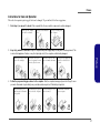
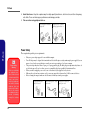
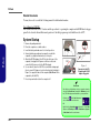
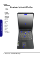
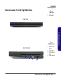
Preface Instructions for Care and Operation The notebook computer is quite rugged, but it can be damaged. To prevent this, follow these suggestions: 1. Don’t drop it, or expose it to shock. If the computer falls, the case and the components could be damaged. Do not expose the computer to any shock or vibration. 2. Do not place anything heavy on the computer. Keep it dry, and don’t overheat it. Keep the computer and power supply away from any kind of heating element. This is an electrical appliance. If water or any other liquid gets into it, the computer could be badly damaged. Do not leave it in a place where foreign matter or moisture may affect the system. Don’t use or store the computer in a humid environment. Do not place the computer on any surface which will block the vents. Preface Do not expose it to excessive heat or direct sunlight. 3. Do not place it on an unstable surface. Follow the proper working procedures for the computer. Shut the computer down properly and don’t forget to save your work. Remember to periodically save your data as data may be lost if the battery is depleted. Do not turn off the power until you properly shut down all programs. Do not turn off any peripheral devices when the computer is on. Do not disassemble the computer by yourself. Perform routine maintenance on your computer. V Preface 4. 5. Avoid interference. Keep the computer away from high capacity transformers, electric motors, and other strong magnetic fields. These can hinder proper performance and damage your data. Take care when using peripheral devices. Use only approved brands of peripherals. Unplug the power cord before attaching peripheral devices. Preface Power Safety The computer has specific power requirements: VI • • Power Safety Warning • Before you undertake any upgrade procedures, make sure that you have turned off the power, and disconnected all peripherals and cables (including telephone lines and power cord). It is advisable to also remove your battery in order to prevent accidentally turning the machine on. • • • Only use a power adapter approved for use with this computer. Your AC adapter may be designed for international travel but it still requires a steady, uninterrupted power supply. If you are unsure of your local power specifications, consult your service representative or local power company. The power adapter may have either a 2-prong or a 3-prong grounded plug. The third prong is an important safety feature; do not defeat its purpose. If you do not have access to a compatible outlet, have a qualified electrician install one. When you want to unplug the power cord, be sure to disconnect it by the plug head, not by its wire. Make sure the socket and any extension cord(s) you use can support the total current load of all the connected devices. Before cleaning the computer, make sure it is disconnected from any external power supplies. Do not plug in the power cord if you are wet. Do not use the power cord if it is broken. Do not place heavy objects on the power cord. Preface Battery Precautions • Only use batteries designed for this computer. The wrong battery type may explode, leak or damage the computer. • Do not continue to use a battery that has been dropped, or that appears damaged (e.g. bent or twisted) in any way. Even if the computer continues to work with a damaged battery in place, it may cause circuit damage, which may possibly result in fire. • Recharge the batteries using the notebook’s system. Incorrect recharging may make the battery explode. • Do not try to repair a battery pack. Refer any battery pack repair or replacement to your service representative or qualified service personnel. • Keep children away from, and promptly dispose of a damaged battery. Always dispose of batteries carefully. Batteries may explode or leak if exposed to fire, or improperly handled or discarded. • Keep the battery away from metal appliances. • Affix tape to the battery contacts before disposing of the battery. • Do not touch the battery contacts with your hands or metal objects. Battery Guidelines Preface The following can also apply to any backup batteries you may have. • If you do not use the battery for an extended period, then remove the battery from the computer for storage. • Before removing the battery for storage charge it to 60% - 70%. • Check stored batteries at least every 3 months and charge them to 60% - 70%. Battery Disposal The product that you have purchased contains a rechargeable battery. The battery is recyclable. At the end of its useful life, under various state and local laws, it may be illegal to dispose of this battery into the municipal waste stream. Check with your local solid waste officials for details in your area for recycling options or proper disposal. Caution Danger of explosion if battery is incorrectly replaced. Replace only with the same or equivalent type recommended by the manufacturer. Discard used battery according to the manufacturer’s instructions. Battery Level Click the battery icon in the taskbar to see the current battery level and charge status. A battery that drops below a level of 10% will not allow the computer to boot up. Make sure that any battery that drops below 10% is recharged within one week. VII Preface Related Documents You may also need to consult the following manual for additional information: User’s Manual on CD/DVD This describes the notebook PC’s features and the procedures for operating the computer and its ROM-based setup program. It also describes the installation and operation of the utility programs provided with the notebook PC. System Startup Remove all packing materials. Place the computer on a stable surface. Insert the battery and make sure it is locked in position. Securely attach any peripherals you want to use with the computer (e.g. keyboard and mouse) to their ports. 5. Attach the AC/DC adapter to the DC-In jack at the rear of the computer, then plug the AC power cord into an outlet, and connect the AC power cord to the AC/DC adapter. 6. Use one hand to raise the lid/LCD to a comfortable viewing angle (do not exceed 135 degrees); use the other hand (as illustrated in Figure 1) to support the base of the computer (Note: Never lift the computer by the lid/LCD). 7. Press the power button to turn the computer “on”. Preface 1. 2. 3. 4. 135° Figure 1 Opening the Lid/LCD/ Computer with AC/DC Adapter Plugged-In Shut Down Note that you should always shut your computer down by choosing the Shut down command in Windows (see below). This will help prevent hard disk or system problems. Click the icon in the Start Screen and choose Shut down from the menu. Or Right-click the Start button at the bottom of the Start Screen or the Desktop and choose Shut down or sign out > Shut down from the context menu. VIII Introduction Specifications Processor Options Video Adapter Intel® Core™ i7 Processor Intel® Integrated GPU and NVIDIA® Discrete GPU i7-4870HQ (2.50GHz), i7-4720HQ (2.60GHz) Supports Microsoft Hybrid Graphics 6MB L3 Cache, 22nm, DDR3L-1600MHz, TDP 47W Latest Specification Information Intel® Core™ i5 Processor i5-4210H (2.90GHz) 3MB L3 Cache, 22nm, DDR3L-1600MHz, TDP 47W The specifications listed here are correct at the time of sending them to the press. Certain items (particularly processor types/speeds) may be changed, delayed or updated due to the manufacturer's release schedule. Check with your service center for more details. Core Logic Intel® HM87 Chipset 1.Introduction BIOS 48Mb SPI Flash ROM AMI BIOS Memory CPU Two 204 Pin SO-DIMM Sockets Supporting DDR3L 1600MHz Memory Memory Expandable up to 16GB The CPU is not a user serviceable part. Accessing the CPU in any way may violate your warranty. (The real memory operating frequency depends on the FSB of the processor.) Storage (Factory Option) One 9.5mm(h) Optical Device Type Drive (Super Multi Drive) (Factory Option) 2.5" 9.5mm 2nd HDD/SSD caddy One Changeable 2.5" 9.5mm/7.0mm (h) SATA HDD/SSD Intel Integrated GPU Intel® HD Graphics 5200 (Core i7-4870HQ/ i7-4770HQ/ Dynamic Frequency (Intel Dynamic Video Memory Technology for up to 1.7GB) Microsoft DirectX®11.1 Compatible Intel® HD Graphics 4600 (Core i7-4720HQ/ i5-4210H Dynamic Frequency (Intel Dynamic Video Memory Technology for up to 1.7GB) Microsoft DirectX®11.1 Compatible NVIDIA® Discrete GPU NVIDIA® GeForce GTX 960M 2GB GDDR5 Video RAM on board Microsoft DirectX® 12 Compatible Audio High Definition Audio Compliant Interface 2 * Built-In Speakers Built-In Microphone Sound Blaster™ Cinema 2 Security Security (Kensington® Type) Lock Slot LCD Options BIOS Password (Factory Option) Fingerprint Reader (Factory Option) TPM v 2.0 17.3" (43.94cm) FHD Keyboard Illuminated Full-size “WinKey” keyboard (with numeric keypad) 1 - 2 Specifications Introduction Pointing Device Card Reader Built-in Touchpad Embedded Multi-In-1 Card Reader MMC (MultiMedia Card) / RS MMC Interface Four USB 3.0 Ports One Mini DisplayPort One HDMI-Out Port One External Monitor Port One Headphone-Out Jack One Microphone-In Jack One S/PDIF Out Jack One RJ-45 LAN Jack One DC-in Jack Slot 1 for M.2 2230 WLAN Combo Module Card with PCIe & USB Interfaces Slot 2 for M.2 2280 SSD Card with SATA/ PCIe x2/ x4 Interface Communication Built-In Gigabit Ethernet LAN (Factory Option) 2.0M FHD PC Camera Module Environmental Spec Temperature Operating: 5°C - 35°C Non-Operating: -20°C - 60°C Relative Humidity Operating: 20% - 80% Non-Operating: 10% - 90% Power 1.Introduction M.2 Slots SD (Secure Digital) / Mini SD / SDHC/ SDXC Full Range AC/DC Adapter AC Input: 100 - 240V, 50 - 60Hz DC Output: 19.5V, 6.15A (120W) Built-in 6 Cell Smart Lithium-Ion Battery Pack, 62WH Dimensions & Weight 413mm (w) * 285mm (d) * 31.9mm (h) 2.9kg (Barebone with 62WH Battery) WLAN/ Bluetooth M.2 Modules: (Factory Option) Intel® Wireless-AC 7265 Wireless LAN (802.11ac) + Bluetooth 4.0 (Factory Option) Intel® Wireless-N 7265 Wireless LAN (802.11b/g/n) + Bluetooth 4.0 (Factory Option) Intel® Wireless-AC 3160 Wireless LAN (802.11ac) + Bluetooth 4.0 (Factory Option) Qualcoumm® Atheros Killer™ Wireless-AC 1525 Dual Band 2x2 AC +BT M.2 1630 (Factory Option) Third-Party Wireless LAN 802.11b/g/n + Bluetooth 4.0 Specifications 1 - 3 Introduction Figure 1 External Locator - Top View with LCD Panel Open 1.Introduction Top View 1. PC Camera 2. *PC Camera LED *When the PC camera is in use, the LED will be illuminated. 3. Built-In Array Microphone 4. LCD 5. Speakers 6. Power Button 7. Keyboard 8. Touchpad & Buttons 9. Fingerprint Reader (Optional) 2 1 4 5 5 6 7 8 9 1 - 4 External Locator - Top View with LCD Panel Open 3 Introduction External Locator - Front & Right Side Views Figure 2 Front View 1. LED Indicator FRONT VIEW 1 1. Multi-in-1 Card Reader 2. USB 3.0 Port 3. External Monitor Port 4. RJ-45 LAN Jack RIGHT SIDE VIEW 1 2 3 4 External Locator - Front & Right Side Views 1 - 5 1.Introduction Figure 3 Right Side View Introduction External Locator - Left Side & Rear View Figure 4 Left Side View 1.Introduction 1. 2. 3. 4. Security Lock Slot USB 3.0 Ports S/PDIF-Out Jack Microphone-In Jack 5. Headphone-Out Jack 6. Optical Device Drive Bay 7. Emergency Eject Hole / LEFT SIDE VIEW 1 2 2 3 4 Figure 5 6 5 7 REAR VIEW Rear View 1. 2. 3. 4. 5. Vent USB 3.0 Port HDMI-Out Port Mini Display Port DC-In Jack 1 - 6 External Locator - Left Side & Rear View 1 2 3 4 5 1 Disassembly Chapter 2: Disassembly Overview This chapter provides step-by-step instructions for disassembling the N170SD series notebook’s parts and subsystems. When it comes to reassembly, reverse the procedures (unless otherwise indicated). We suggest you completely review any procedure before you take the computer apart. To make the disassembly process easier each section may have a box in the page margin. Information contained under the figure # will give a synopsis of the sequence of procedures involved in the disassembly procedure. A box with a lists the relevant parts you will have after the disassembly process is complete. Note: The parts listed will be for the disassembly procedure listed ONLY, and not any previous disassembly step(s) required. Refer to the part list for the previous disassembly procedure. The amount of screws you should be left with will be listed here also. Information A box with a will also provide any possible helpful information. A box with a contains warnings. An example of these types of boxes are shown in the sidebar. Warning Overview 2 - 1 2.Disassembly Procedures such as upgrading/replacing the RAM, optical device and hard disk are included in the User’s Manual but are repeated here for your convenience. Disassembly Removing the Battery 1. 2. 3. 4. Figure 1 Battery Removal Turn the computer off, and turn it over. Locate the battery and remove screws 1 - 2 (Figure 1a). Carefully lift the battery 3 up in the direction of the arrow 4 (Figure 1b). Remove the battery off the computer (Figure 1c). a. Remove the screws. b. Lift the battery. c. Remove the battery. b. a. 1 2 4 2.Disassembly 3 c. 3 3. Battery • 2 Screws Removing the Battery 2 - 5 Disassembly Figure 2 2.Disassembly Keyboard Removal a. Remove the screws and component bay cover. b. Remove the screws. c. Eject the keyboard using a special eject stick to push the keyboard out while releasing the keyboard as shown. d. Lift the keyboard up and disconnect the keyboard ribbon cable from the locking collar socket. Removing the Keyboard 1. 2. 3. 4. Turn off the computer, turn it over to remove the battery (page 2 - 5). Remove screws 1 - 3 (screw size = M2.5x5L) and the component bay cover 4 (Figure 3a). Remove screws 5 - 6 (screw size = M2.5x8L) to release the keyboard (Figure 3a). Open it up with the LCD on a flat surface before pressing at point 7 to release the keyboard module (use the special eject stick to do this) while releasing the keyboard in the direction of the arrow 8 as shown (Figure 3b). 5. Carefully lift the keyboard 9 up, being careful not to bend the keyboard ribbon cable 10 . Disconnect the keyboard ribbon cable 10 from the locking collar socket by using a flat-head screwdriver to pry the locking collar pins 11 away from the base (Figure 3c). a. 2 1 c. 3 4 8 7 d. b. 9 10 4. Component Bay Cover 9. Keyboard • 5 Screws 2 - 6 Removing the Keyboard 7 5 6 11 11 10 11 Disassembly 6. Carefully lift the keyboard 9 off the computer (Figure 3e). Figure 3 Keyboard Removal e. Remove the keyboard. e. 9 Re-inserting the Keyboard When re-inserting the keyboard firstly, align the keyboard tabs at the bottom of the keyboard with the slots in the case. 9. Keyboard Removing the Keyboard 2 - 7 2.Disassembly Disassembly Figure 4 HDD Assembly Removal a. Remove the screws and HDD cover. b. Slide the HDD in the direction of the arrow. Removing the Hard Disk Drive The hard disk drive can be taken out to accommodate other 2.5" serial (SATA) hard disk drives with a height of 9.5mm or 7mm (h). Follow your operating system’s installation instructions, and install all necessary drivers and utilities (as outlined in Chapter 4 of the User’s Manual) when setting up a new hard disk. Hard Disk Disassembly Process 1. Turn off the computer, remove the battery (page 2 - 5) and keyboard (page 2 - 6). 2. Remove screws 1 - 2 and HDD cover 3 (Figure 4a). 3. Remove screws 4 - 5 and then slide the hard disk out in the direction of arrow 6 (Figure 4b). 2.Disassembly a. b. 1 2 4 6 Screw Size 5 Note that the size of screws 1 & 2 is M2.5 x 5L. 3. HDD Cover • 4 Screws 2 - 8 Removing the Hard Disk Drive 3 Disassembly 4. Lift the hard disk assembly 7 out of the bay 8 (Figure 5c). 5. Remove screws 9 - 11 and separate the hard disk 12 from the bracket 13 and mylar cover 14 (Figure 5d). 6. Reverse the process to install a new hard disk (do not forget to insert the mylar cover between the bracket and hard disk as shown before replacing the screws). d. c. 10 11 Installing 9.5mm or 7mm HDD Figure 5 HDD Assembly Removal (cont’d.) c. Lift the HDD assembly out of the bay. d. Separate the HDD, mylar cover and bracket. 28 Note that the hard disks pictured on the 8 25 13 following pages are all 9.5mm(h) hard disk drive. In some cases, a 7.0mm(h) hard disk drive will be installed. Do pay attention on the alignment of the hard disk and bracket when tightening the screws. 12 2.Disassembly 9 14 For more information, contact your distributor/supplier, and bear in mind your warranty terms. 7 HDD System Warning New HDD’s are blank. Before you begin make sure: You have backed up any data you want to keep from your old HDD. You have all the CD-ROMs and FDDs required to install your operating system and programs. If you have access to the internet, download the latest application and hardware driver updates for the operating system you plan to install. Copy these to a removable medium. 7. HDD Assembly 12. HDD 13. Bracket 14. Mylar Cover • 3 Screws Removing the Hard Disk Drive 2 - 9 Disassembly Hard Disk Size Note (Foam Rubber Insert) Note that the hard disks pictured on the following pages are all 9.5mm(H) hard disk drives. In some cases 7mm(H) hard disk drives will be installed. Also pay attention on the alignment of the hard disk and bracket when tightening the screws. For more information contact your distributor/supplier, and bear in mind your warranty terms. 2.Disassembly Figure 6 Foam Rubber Insert for 7mm(H) HDDs • If you are replacing a 9.5mm(H) HDD with a 7mm(H) HDD then insert the foam rubber insert (as shown above). • If you are replacing a 7mm(H) HDD with a 9.5mm(H) HDD then remove the foam rubber insert. 2 - 10 Removing the Hard Disk Drive Disassembly Removing the 2nd Hard Disk from Caddy Bay 1. 2. 3. 4. 5. 6. 7. 8. Figure 7 2nd HDD Removal Turn off the computer, remove the battery (page 2 - 5), and bottom case (page 2 - 8). Carefully push out the caddy bay 61 out in the direction of the arrow 2 (Figure 7a). Remove screws 3 - 4 (will depends on the HDD type) from the bottom of the caddy bay. Remove screws 5 - 6 to release the hard disk assembly (Figure 7b). Lift the hard disk assembly 7 out of the caddy bay 8 (Figure 7c). Separate the hard disk 9 and connector board 10 (Figure 7d). Reverse the process to install a new hard disk. Restart the computer to allow it to automatically detect the new device. a. Push the caddy bay out off the computer. b. Remove the screws. c. Lift the hard disk assembly out of the caddy bay d. Separate the hard disk and connector. c. a. 2.Disassembly 1 8 2 7 b. 3 5 d. 6 9 4 10 1. Dummy Bay 7. HDD Assembly 9. Hard Disk 10. Connector Board • 4 Screws Removing the 2nd Hard Disk from Caddy Bay 2 - 11 Disassembly Figure 8 Optical Device Removal a. Remove screw and push the optical device out off the computer. b. Pry the bezel off the optical device. c. Separate the bezel and optical device d. Install the front bezel. Removing the Optical (CD/DVD) Device 1. 2. 3. 4. 5. 6. Turn off the computer, remove the battery (page 2 - 5), and bottom case (page 2 - 8). Remove screw 1 and carefully push the optical device 62 out of the bay at point 3 (Figure 8a). Carefully pry the bezel 5 off the optical device at point 4 (Figure 8b). Separate the bezel 5 and the optical device as shown (Figure 8c). Reverse the process to attach the front bezel 5 with the new optical device at point 6 (Figure 8d). Insert the new device and carefully slide it into the computer (the device only fits one way. DO NOT FORCE IT; The screw holes should line up). Replace the bottom cover and tighten the screws. 7. Restart the computer to allow it to automatically detect the new device. 2.Disassembly a. 2 1 3 Screw Size Note that the size of screw 1 is M2 x 8L. b. 1. Optical Device 4. Bezel Cover 2 - 12 Removing the Optical (CD/DVD) Device d. c. 4 5 5 6 Disassembly Removing the System Memory (RAM) Figure 9 The computer has two memory sockets for 204 pin Small Outline Dual In-line Memory Modules (SO-DIMM) supporting DDR3L up to 1600 MHz. The main memory can be expanded up to 32GB. The total memory size is automatically detected by the POST routine once you turn on your computer. Memory Upgrade Process c. b. a. 2 a. The RAM modules will be visible at point 1 on the mainboard. b. Pull the release latches. c. Remove the module. Contact Warning Be careful not to touch the metal pins on the module’s connecting edge. Even the cleanest hands have oils which can attract particles, and degrade the module’s performance. 3 1 4 4. RAM Module Removing the System Memory (RAM) 2 - 13 2.Disassembly 1. Turn off the computer, remove the battery (page 2 - 5) and keyboard (page 2 - 6). 2. The RAM modules will be visible at point 1 on the mainboard (Figure 9a). 3. Gently pull the two release latches ( 2 & 3 ) on the sides of the memory socket in the direction indicated by the arrows (Figure 9b). The RAM module 4 will pop-up (Figure 9c), and you can then remove it. 4. Pull the latches to release the second module if necessary. 5. Insert a new module holding it at about a 30° angle and fit the connectors firmly into the memory slot. 6. The module will only fit one way as defined by its pin alignment. Make sure the module is seated as far into the slot as it will go. DO NOT FORCE IT; it should fit without much pressure. 7. Press the module in and down towards the mainboard until the slot levers click into place to secure the module. 8. Replace the bottom cover and the screws (see page 2 - 5). 9. Restart the computer to allow the BIOS to register the new memory configuration as it starts up. RAM Module Removal Disassembly Figure 10 M.2 SSD Module Removal a. Locate the M.2 SSD. b. Remove the screw. c. The M.2 SSD module will pop up. Removing the M.2 SSD Module 1. 2. 3. 4. 5. Turn off the computer, remove the battery (page 2 - 5), keyboard (page 2 - 6) and bottom case (page 2 - 8). The M.2 SSD module will be visible at point 1 on the mainboard (Figure 10a). Remove the screw 2 (Figure 10b) The M.2 SSD module 3 (Figure 10c) will pop-up, and you can remove it from the computer. Reverse the process to install a new SSD module (make sure that the thermal pad is in place as shown below). c. a. 2.Disassembly 3 1 b. 2 3.M2 SSD Module • 1 Screw 2 - 14 Removing the M.2 SSD Module 3 Disassembly Removing the Wireless LAN Module 1. 2. 3. 4. Figure 11 Turn off the computer, remove the battery (page 2 - 5), keyboard (page 2 - 6) and bottom case (page 2 - 8). The Wireless LAN module will be visible at point 1 on the mainboard (Figure 11a). Carefully disconnect the cables 2 & 3 , and then remove the screw 4 (Figure 11b) The Wireless LAN module 5 (Figure 11c) will pop-up, and you can remove it from the computer. c. a. Wireless LAN Module Removal a. Locate the WLAN. b. Disconnect the cables and remove the screw. c. The WLAN module will pop up. 1 b. 2 5 4 3 5.Wireless LAN Module • 1 Screw Removing the Wireless LAN Module 2 - 15 2.Disassembly Note: Make sure you reconnect the antenna cable to the “1 + 2” socket (Figure 11b). 5 Disassembly Wireless LAN, & Combo Module Cables Note that the cables for connecting to the antennae on WLAN, WLAN & Bluetooth Combo, 3G and LTE modules are not labelled. The cables/covers (each cable will have either a black or transparent cable cover) are color coded for identification as outlined in the table below. Module Type 2.Disassembly WLAN/WLAN & Bluetooth Combo Antenna Type Cable Color WM 1 Black WM 2 Gray WM 3 White Cable Cover Type Transparent Cable 1 is usually connected to antenna 1 (Main) on the module, and cable 2 to antenna 2 (Aux). 2 - 16