1
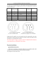
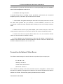
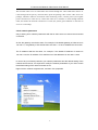
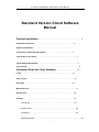
IP Camera and Network Video Server User Manual
Standard Version Client Software
Manual
Product Installation…………………………………………………………………3
Installation Instruction………………………………………………………………3
Hardware Installation…………………………………………………………………
Connection for Network Video Server…………………………………………7
Connection for IP camera……………………………………………………………7
Check Network Parameters……………………………………………………………7
Connect Test………………………………………………………………………………9
Operation Guide for Client Software ………………………………15
Login…………………………………………………………………………………15
View Control……………………………………………………………………………16
Play/ Stop……………………………………………………………………………16
Manual Record……………………………………………………………………………17
Play Record……………………………………………………………………………18
Settings……………………………………………………………………………19
1>Local Set………………………………………………………………………19
2>Channel Set………………………………………………………………………22
3>Assign IP…………………………………………………………………………23
4>Reindex Record………………………………………………………………………24
1
IP Camera and Network Video Server User Manual
Basic and advanced Control………………………………………………………25
Snapshot…………………………………………………………………………………26
Camera Option…………………………………………………………………………26
1>Video…………………………………………………………………………26
2>Audio…………………………………………………………………………27
3>Network………………………………………………………………………27
4> OSD……………………………………………………………………28
5>User Management…………………………………………………………………29
6>About…………………………………………………………………………29
Statement Display…………………………………………………………………………30
Multi-image switch……………………………………………………………30
Show Channel Number………………………………………………………………31
OSD……………………………………………………………………………31
Display Time……………………………………………………………………………31
Motion Detection…………………………………………………………………………32
Notice……………………………………………………………………………32
2
IP Camera and Network Video Server User Manual
Product Introduction
Thank you for choosing our product. Besides all functions of traditional camera,
network camera, as a new product combining traditional camera with network video
technologies, has been incorporated with a built-in digital compression controller and
WEB-based operating system, which enables transferring the compressed and
enciphered data to the end user through LAN, Internet or wireless network. The remote
user, by using standard network browser or the client software in his/her own PC, may
access to the network camera by its independent IP address, and fulfill real-time
monitoring of target site, real-time edition and storage of video data; moreover, the user
may implement omnidirectional monitoring by controlling the pan/tilt and lens of
network camera via network.
The hardware of network camera includes network video service module and CCD
module, which can work as soon as connected with power and network cable, without
the necessity for connecting the computer. Only with the software program installed in
the computer, the user can, through network, use IE browser or client software to watch
real-time video and listen the field voice. The network camera has functions such as
network video recording, image framing, video record playback, pan/tilt control and
dynamic motion detection. The transfer speed of image in compression form of MPEG-4
may be up to 25 frame/second on network, thus realize real-time watching without
delay; for the recovery of image, the maximum definition for image quality is D1. For
the application of software, it is extremely easy-to-use, for its interface is provided with
the buttons for pan/tilt operation, lens control and network video, and options for
function setting and administrator setting etc.
Product Characteristics
1) Equipment characteristics
It consists of three parts: network camera, player software for network camera and
configuration software for network camera.
9 D1 high-definition image, fluent voice, with various display formats
9 Support IE browse
9 MPEG-4 high compression ratio arithmetic
9 Applicable to network environment of ADSL, LAN, etc.
9 Transfer speed for image up to 25 frame/second
9 With the function of dynamic motion detection, and the sensibility of detection is
adjustable
9 Support the capture and archiving of individual image in the format of JPG and
3
IP Camera and Network Video Server User Manual
BMP
9 Support parameter setting on Internet with easy update
9 Support characters overlap
9 Automatically search IP and connect it
9 Encryption function for image
9 Multiple protocol support-TCP/IP, HTTP, ARP and RARP, etc.
Security
Account number, password, user privilege
Alarm
Video image dynamic motion detection
Control of pan/tilt and
lens
RS485 interface, remote control of pan/tilt and electronic lens by
client
Requirements to
computer
Windows2000/XP Version
IE 4.0 version or above
NET4.5 version or above
CPU
32Bit RSIC Embedded Processor
Operating
system
Embedded Linux system
Network
protocol
Support TCP/IP,HTTP,ARP,RARP, etc.
Network
interface
RJ45 10/100m Self-adaptive to Ethernet network interface
Compression
MPEG-4
Frame
frequency
10-30fps (D1)
Resolution
D1:720×576 CIF:320×288 FIELD:720×288 QCIF:192×144
Input
1Ch
Output
1Ch
Sensor
1/3 Sony CCD,420 bus ,32MM×32MM
Signal-to-Noise
More than 48DB (automatic gain is off)
Lens interface
C/CS lens interface
Automatic
white balance
Automatic white balance
Back light
compensation
Automatic back light compensation
Hardware
Network
Video
CCD
module
Camera power
Power: DC 12V, Current 1A
Application scope
Enterprise, community, government institutions , traffic, power,
financing and national defense etc.
4
IP Camera and Network Video Server User Manual
2) Network Characteristics
1> User-defined http port-allows the gateway of Internet to use “port mapping”,
therefore the network video/audio products and web server may share one Internet IP
address.
2> Support DDNS to release network video/audio products to Internet through
secondary dynamic domain name resolution.
3) Security Characteristics
1> User identification: if necessary, only known user is allowed to access real-time
video, before that, user must input user name and password. The maximum number of
users is 5.
2> Security: password protection and IP filtering, MAC filtering
3> Motion Detection
Panel structure
POWER/STATUS LED
Power on: Yellow light on LAN is uninterruptedly on
NETWORK LED
Network link (connected): Two lights on LAN are uninterruptedly on
In transformation of signal: Green light flashes in high frequency, 10/100M
self-adaptive
Network disconnection: Green light is off
LAN
RJ-45 port may connect with Grade-5 twisted pair wire (IEEE802.3 10Base T
standard)
DC 12V
The specification of DC input power is 12V; a DC power with AC 100-240 input
and DC 12V 1A output is packed with the camera (Please use the power packed
with the camera or else improper use of power may easily damage the core).
RS485
5
IP Camera and Network Video Server User Manual
The camera has a pan/tilt RS485 port, which may be connected with pan/tilt decoder
to realize pan/tilt control; it supports protocol PELCO-P with baud rate at 9600 and
effective address at 0.
Pin number
Color of
corresponding lead
wire
Signal purpose
Signal
direction
Pin 1
Purple
I/O Channel
Pin 2
Black
RS485+
Output
Pin 3
Grey
RS485-
Input
Pin 4
Yellow
I/O Channel
Output
Pin 5
Green
I/O Channel
Input
Pin 6
Blue
Pin 7
Orange
Pin 8
Red
Remarks
Input
COM
I/O Channel
Output
I/O GND
Layout of each pin numbering
in 8-core S terminal socket
Layout of each pin numbering of
connection wire plug in 8-core S terminal
Connect the 485+ and 485- wire on S terminal to the 485+ pole and 485- pole on the
PTZ decoder or decoder kit; set the protocol of decoder as PELCO-P baud rate 9600
with address on 0 through DIP on decoder.
The alarm signal is input or output on the I/O channel,but this function
is not ready now,we will build it in the future.
Product Installation
1)Installation Instruction
Thank you for choosing our products. Before use our products, please read
carefully and understand all safety instructions before installation
The package of IP camera shall include:
6
IP Camera and Network Video Server User Manual
A. IP Camera
B. Power adaptor
C. 8-core terminal connection wire
D. Installation disc
E. User Manual
F. 1m cable
The inner part of the camera manly consists of two parts: network video server and CCD
module. Since we do not provide optical lens, users may select lens by themselves
according to actual needs.
Use cable to directly connect computer with other computers or LAN through router. The
terminal of IP camera shall be installed indoor; waterproof cover or lightning-proof facility
shall be considered if installed outdoor.
Do not touch lens since it may leave fingerprint which results in blurred or invisible image;
only maintainer authorized by the manufacturer is allowed to repair the terminal of this IP
camera.
Please return the network video/audio products to our company for repair in case the
followings happen:
Power or plug is damaged
When liquid leaks into network video/audio products
Network video/audio products are damaged arising from falling
Network video/audio products fail to work normally after setting and adjustment according to
the operation manual.
2)Hardware installation:
1> Installation of lens
The installation of lens for IP camera supports the types of C and CS. The screw threads of
both types are 1 inch 32 thread with diameter in 1 inch and the difference lies in their
distance from lens to CCD board. For the C-type installation base, the distance from base
level to the focus is 17.562 mm, which is longer than that of CS type from CCD board of the
length of a special adapter ring; since the distance from CS-type lens to focus is 12.5mm, an
adapter ring of lens is required for C-type installation; meanwhile, an after-image adjustment
ring at the installation port of IP camera is used for the after-image adjustment. During the
adjustment, use the screwdriver to loose the screw on the side of adjustment ring and turn
7
IP Camera and Network Video Server User Manual
the adjustment ring, then the CCD format will move forward (backward) from the installation
base to fulfill the adjustment of lens focus.
2> Installation and fixing instruction
A standard fixing base for installing camera (M5 British measurement) is incorporated
respectively on the up and down part on the shell of IP Camera.
3> Internet cable: Use grade-5 twisted pair wires and RJ-45 (LAN) connector to connect
the video/ audio products with your network; it is also available to connect it to the
concentrator or switcher through standard cable or directly connect to PC through crossover
cable.
4> Make sure the norms of your power adapter (110V or 220 V AC input, 12V.1A DC
output) match the power line; and connect the power with network video/audio products.
5> Check if the LED on the power indicator LAN is on or not; the connection indicator
LAN is on if the connection of network is correct.
6> The IP address of the PC shall be set in the same IP address of video/audio, for
example, if the initial IP address of network products is 192.168.1.126, the IP address of PC
shall be set between 92.168.1.2 and 192.168.1.255.
Connection for Network Video Server
The default network settings of network video server produced by our company are:
IP: 192.168.1.126
Gateway: 192.168.1.1
Subnet mask: 255.255.255.0
DNS server: 168.95.1.1
The IP address or gateway of IP camera and video server is changeable. It shall be noted
that if the IP or gateway is changed, the IP address of PC shall be changed into the same IP
address of IP camera, as well as the gateway the same as that of camera.
Connection for IP camera
8
IP Camera and Network Video Server User Manual
The network video server is connected to the camera through AV video cable and to the PC or
router through RJ 45 port by network cable. Open the package, take out the video server for
package, install the software of network video monitoring on PC, connect power (use original
power connection) to video server, connect the video server with PC or router through network
cable, and ensure the network connection is correct (the yellow-green indicator on the back of
server is on normally).
Check network parameters
Only matching of PC network parameters with that of video sever can ensure the successful
connection.
At first, the gateway must be the same. For example, if the default gateway of video server is
192.168.1.1, the gateway of PC shall be also 192.168.1.1 so as to establish the connection.
The IP address shall be the same, for example, if the default IP address of camera is
192.168.1.126, the IP address of PC shall be one of the addresses in 192.168.1.0~255.
In case of any inconformity between your network parameters and the default setting of the
network camera server, it is required to modify the network parameters of your PC to match
the default setting of the network camera server.
Right click the ‘network neighborhood’, and then click ‘properties’
9
IP Camera and Network Video Server User Manual
Double-click ‘Internet protocol (TCP/ IP)’ to check the current network parameters
10
IP Camera and Network Video Server User Manual
Connection Test
After confirmation the conformity of the settings for your network setting and network video
server, and then click ‘Start’—>’Operation’, input ‘ping. network video server IP. –t’ (input
‘ping 192.168.1.126 –t’ for camera with unchanged setting) in the dialogue box, use the ping
order to ensure whether the connection of network video server is correct:
The data displayed in the picture means the correct connection of network video server:
11
IP Camera and Network Video Server User Manual
Provided that your original network parameters is not in conformity with default network
parameters of the network video server, the network parameters of network video server of
the client software may be modified to your original network parameters after the connection
of network video server, then the network video server may be connected with your whole
network after changed the network parameters of your PC into the original one.
Operation Guide for Client Software
Login
Double click ‘ Client’ on the desktop icon or click ‘start’ -----> ‘procedure’----->’Client
Software’, Loginbox will come:
12
IP Camera and Network Video Server User Manual
Enter username and password(Default set: username: admin,password: admin), click
‘ OK’ to enter the client.
View Control
Current date and time will show on the right-up of the screen.
Under the time display area is View Control area which contains 4 options: Play, Play
Record, Settings, Manual Record.
13
IP Camera and Network Video Server User Manual
Display: Set IP information to all the channels and click ’Play’ or click right button to
choose ‘Live Play’ on the certain channel, and then the certain channel will play the
real video picture.
Channel number, Play state, frame rate, bit stream and IP address will shows on the top:
Stop: When the channel is on play state, the ‘play’ button will change to’ Stop’ , click ‘Stop’
14
IP Camera and Network Video Server User Manual
to stop all the play channel.
Manual Record: Click the ‘Manual Record’, the client starts to record directly and save as
AV Format, it finishes one file as 15 minutes.
Click the right button to choose ‘AV Format’ or ‘AVI Format’, and choose save
file path as click ‘settings’—‘Local Setting’—‘ Disks Setting’, shows as the
following:
When start recording, ‘Manual Record’ becomes to ‘Stop Record’, ‘REC’ display on the
right -up of the screen.
Click ‘Stop Record’ to stop record state.
Play Record:Click ’Play Record’ to open the display record surface, and then you should
choose the record file you need, shows as follows:
Double click the file you need, it begins to display and the record time is shown on the
right-bottom of the screen.
15
IP Camera and Network Video Server User Manual
Settings:Click ’Settings’, there are 4 options: Local setting, Channel setup, Assign IP,
Reindex record
There are 6 options in ‘Local Setting’: Disc Setting, Users, Snapshot, UI Style, Log, About.
16
IP Camera and Network Video Server User Manual
1> Disks Setting
Shows as follows:
17
IP Camera and Network Video Server User Manual
Set save path for the record file, the record file will be saved at chosen disk. When one
disk is full, the file will be saved in next chosen disk. If all the disks are full, the earliest file will
be deleted. (200MB as a unit)
You could set: When disk space less than which you set, it saves directly to next disk;
and when all the disks are full, it deletes how many files.
2> Users
You could add or delete the users, and also modify users’ information (Default ‘admin’ can
not be deleted)
3> Snapshot
18
IP Camera and Network Video Server User Manual
Set BMP or JPG format to save the snapshot. Choose adding the time on or not while set
the font color and the saving path.
4> UI Style
Our client supply 10 different types surface to suit different needs.
19
IP Camera and Network Video Server User Manual
5> Log
It includes Login time, Login result, and Username. All the contents list in terms of the day.
6> About
It contains some simple description for Client system.
20
IP Camera and Network Video Server User Manual
You could set the Parameter, Schedule information and Platform in ‘Channel Setup’,
Click from ‘Channel 1’ to ‘Channel 64’ to set each camera’s Parameter, Schedule Table,
Platform. Shows as follows:
Click ‘Channel Parameter’, you could set Camera IP, Port number, Username, Password,
set Rotation angle for the display picture and also Display OSD.
21
IP Camera and Network Video Server User Manual
Click ‘Schedule Table’, shows as follows:
Record Type: Schedule Record, Alarm Record
Click ‘Schedule’ record, set the time in the “Start Time” and “End time”, and then click
“Add”. The record task will display in the list.
Platform
22
IP Camera and Network Video Server User Manual
Set the rotation angle, time of auto-rotation with single way, range of Zoom out and Zoom
in.
Assign IP
Our Client software supply 64 Channels view at the same time, you could set IP
information for all channels here: IP address, port number, username, password.
Take 33ch as example, enter IP: 192.168.1.126, port number: 80, username: admin,
password: (blank), and click ‘OK’ to save.(or click right button on the channel, and
choose ’Live Play), now the IP information display on 33ch is what you set.
23
IP Camera and Network Video Server User Manual
Or use right button to choose ’Set IP address’ to set IP information for each channel.
24
IP Camera and Network Video Server User Manual
All Channels IP information column also accept the English Domain name, Eg: enter:
szsuv.vicp.net
‘ Reindex Record’
Establish the index relationship between client and record file again, it often uses when
25
IP Camera and Network Video Server User Manual
re-install client software.
Basic Control and Advanced Control
Basic Control
Platform Control:
It needs to connect with Platform decoder (set the right protocol, bitrate, right address)
to control platform.
Click the direction arrowhead to control the turn directions for the platform.
Left-up button from the Direction Disk controls All channels Auto Pan.
Right-down button from the Direction Disk controls Auto Pan for the chosen channel.
26
IP Camera and Network Video Server User Manual
The bar down upon the Direction Disk direction adjusts the turn speed of the platform.
(For High-Speed Dome)
Click ‘1’, ‘2’, ‘3’, ‘4’, ‘5’ button to turn directly to1—5 preset point.
Focal length control:
Zoom in, zoom out to control the multiple of the lens.(It needs network video server
connect with camera which has auto Vari-focal lens)
Near, far button to adjust the focal length of the lens. (It needs network video server
connect with camera which has auto Vari-focal lens)
Through keyboard, you could also control the turn, vari-focal functions for platform; up,
down, left, right button on the keyboard to control turn direction; ‘PageUp’ and ‘PageDown’
button control the ‘near’ and ‘far’ functions.
Audio:
Adjust the sound volume of the camera.
Advanced Control
Motion Detection Sensitivity:
For adjusting the sensitivity of capturing the motion when starting the function of motion
detection; If the sensitivity was adjusted to a lower degree, there will be a warning response
only if an obvious motion occurs in the image (a red square could be seen where motion
occurs in the image); if the sensitivity was adjusted to a higher degree, there will be a
warning response even when a light motion occurs.
Brightness: Adjust the brightness of the video image
Saturation: Adjust the color (dark and light) of the video image
Contrast: Adjust the Contrast of the video image
27
IP Camera and Network Video Server User Manual
Set preset point:
Choose number and click
to set the current point which locates at the current picture
as preset point.
Choose number and click
to turn the chosen preset point directly.
Choose number and click
to clear the chosen preset point.
Information for the chosen camera:
IP address: It shows IP address of the chosen camera
Frame rate: It shows at the current time, the transmission of frame amount per second
Bit Rate: Transmission speed for Image data ( K bit/ s )
Snapshot:
Click this button, you could make a snapshot for the current time and save. And
by ’Settings’—‘Local setting’---‘Snapshot’ to choose the save path you need.
Camera Option
Through Click ‘Camera Option’ button or right key to choose ‘option’ on the chosen
channel, you could set the parameters of the camera.
‘Camera Option’ contains: Video, Audio, Network, OSD, Users, About
28
IP Camera and Network Video Server User Manual
1> Video
Video Resolution: There are two formats for setting the quality of video image----QCIF
and D1. D1 provides the best effect. The resolution under PAL and NTSC
systems is shown as below:
D1
CIF
PAL
720*576
352*288
NTSC
720*480
352*240
Compression ratio: Setting the compression degree of data with high or low. The high
compression ratio can improve the transmission rate while the low compression ratio can
restore a truer image, resulting in an image more satisfied.
The maximum frame rate: Setting the maximum frame number of images which can be
transmitted by the camera per second, with an effective value of 1~30 (the defaulted is 30).
P/I ratio: The ratio between P frame and I frame can be changed (the increase of the P/I
ratio can decrease the data volume to-be transmitted), with an effective value of 0~29 (the
defaulted is 15).
Saturation: Setting the saturation of video image, with an effective value of 0~255 (the
defaulted is 0).
Sharpness: for adjusting the edge sawtooth of the image, with an effective value of 0~255
(the defaulted is 128).
Adjust the video according to network condition: automatically set various relevant
parameters of video images according to the actual transmission of the network, and the
relevant function could be enabled by ticking (√) in the blank in front of the function options.
There are two reference object options, namely, the “Image’s Quality” and the “Frame Rate”.
29
IP Camera and Network Video Server User Manual
If you choose the former one, the aim of setting all parameters is to obtain the best image
quality; if the latter one is selected, the aim is to achieve the maximum frames transmitted
per second and for a more stable image transmission.
2> Audio
The setting of video parameters cannot be modified until selecting “Allow Sound”
Audio Compression: set the compression degree of audio data stream
Audio format: set the format of audio compression
Click “OK” to save the setting and exit
3> Network
30
IP Camera and Network Video Server User Manual
IP camera IP Address: display hereof is the IP address of video server connected with the
selected channel, which can be modified here.(After modifying the IP address, normal
operation cannot be resumed until switching off and restarting the server)
Subnet mask: display hereof is the subnet mask of video server connected with the
selected channel, which shall be consistent with that of the serving network (255.255.255.0
generally)
Default gateway: displays hereof is the gateway of video server connected with the
selected channel, which shall be consistent with that of PC machine, otherwise the PC
machine cannot be connected with the video server (any PC machine planed to display the
video pictures of the network camera must be configured with the gateway conforming to
that of the video server after network connection, otherwise there is no way to display the
video pictures)
First DNS: displays hereof is the preferred DNS address of the video server which is in
connection with the selected channel connected with the outer network, which can be
modified here (the setup of this date is of unimportance, if the server has not been
connected with the Internet)
Second DNS: displays hereof is the backup DNS address for the connection with the outer
network of the video server connected with the selected channel, which can be modified
here
Http server port: the port is used for setup of server monitoring, which is usually defaulted
as 80
After setup, click “OK” to save setup and exit (The port set must be HTTP port, otherwise the
server cannot send and receive signal)
31
IP Camera and Network Video Server User Manual
4> OSD
X and Y-axis of character: set up by up and down arrow to change the value or directly
inputting the value, according to the requirement and taking the top left point of the picture as
the origin. The effective value of X-axis is within 0~720; and that of Y-axis is within 0~576.
Character to be overlapped: set the character in the video picture, which supports Chinese
and English input. (After setting the character, click the option of ‘Show OSD’ at the main
interface, and the character you designated shall be displayed at the location you set in the
picture)
Character color: click color bar to enter into color table for selection of the color of adding
character.
After setting, click “OK” to save setup and exit.
5> Users
Add/ delete the user who could connect the IP Products.
32
IP Camera and Network Video Server User Manual
Delete User: Choose the certain user in the user list, and click ‘Delete User’.
Add New User: Enter user name, password into the ’New User’, if need to set it as
administrator, click tick on ‘administrator’, and then click ‘Add User’ to add it.(If don’t click
‘administrator’, it is normal user, normal user can not modify the parameters of the camera)
Current User: It displays current user name, click ’Change Password’ to modify the
password of the current user.
6> About
It is some simple information for Network Video Server and IP Camera.
33
IP Camera and Network Video Server User Manual
Statement Display
The light display the working statement for 1ch—16ch camera
Grey: Stop
Green: Normal Play
Yellow: Record
Red: Motion Detection
Click the statement light to realize functions as stop, play, open the channel option, open
the camera option, set IP address.
Play button: Play the image for all channels(If the channel which doesn’t set IP
address will not display)
Stop button: Stop recording for all channels
Record button: Open manual recording for all channels
Multi-image switch
34
IP Camera and Network Video Server User Manual
Client system has the function of multi-image browse with 7 modes: single picture, 4
pictures, 9 pictures, 16 pictures, 25 pictures, 36 pictures and 64 pictures, among which user
can make the choice according to the need; these modes can be realized by clicking the
button for the corresponding number of cutting channels; full screen browse is possible for
picture transferred through any channel (by using the last button).
Show Channel Number
Click this option, the Number of each channel will display on the right-bottom of the
screen.
Show OSD
Click this option, the words you set in ’Camera Option’----> OSD will display in the
screen of the certain channel.
35
IP Camera and Network Video Server User Manual
Show Time
Click this option, the date and time will display on the right-up of the screen. Each channel
need to set respectively.
Motion Detection
By clicking this item, the Client will produce warning response to any motion appeared in the
picture, and any change between the previous frame and following frame shall generate red
square in the picture, with the precision of the square determined by the sensitivity of motion
detection, as shown in the following picture:
36
IP Camera and Network Video Server User Manual
Notice
1、Working voltage of the product is DC 12V, and please employs the suitable power source
during operation. Excessively low voltage will lead to unstable working condition of the
equipment; too high voltage will burn out the circuit chip.
2、Please remember the user name and password for log-in, if they are got lost, please
return the equipment to the factory for regeneration of chip data, so as to restore the factory
defaults.
3、Measures of lightning protection shall be made during operation; waterproof measures are
required for non-waterproof series products so as to avoid short circuit.
4、Wire pressing method for crystal heads of network cable is recommend to adopt the wiring
method of standard type A or B, so as to achieve the best transmission effect.
37
IP Camera and Network Video Server User Manual
5、The default protocol for platform is Pelco-D 、2400(baud rate), startup with 1 address. For
operation, please select the decoder or decoder board supporting the default protocol,
decoder which does not match protocol or does not support 1 address start cannot control
the pan/tilt normally.
38