1
PIN: 800-0345
SUN-l SYSTEM REFERENCE MANUAL
Draft Version 1.0
July 27, 1 982
The Sun-1 Workstation (TI1 Sun Microsystems Inc.) is a
personal computer system combining high resolution graphics
with Powerful local processing and optional high speed networking. This document is intended to provide all information
needed to install, operate, and program the Sun-1 . Workstation.
This version ('ornpletely supersedes all previous drafts.
Your questions, corrections, and criticisms are welcomed.
Please respond to Martin Rattner or Henry McGilton at Sun
Microsystems, Inc.
Portions or this document are based upon material originally written at Stanford University by William Nowicki, Jeffrey '~ogul, Tim l-mnn, VaughaI~ Pratt, and David Brown, whose
contric· tions are gratefully acknowledged. Used with permission.
Copyright 1982
Sun Microsystems, Inc.
2310 Walsh Avenue
Santa Clara, CA 95051
(lt08) 7lt8-9900
SUN-1 SYSTEM REFERENCE MANUAL
CONTENTS
CONTENTS. • • • • • • • • • • • • • • • • • • • • •.• • • • • • • • • • • • • • • • • • • • • • • • • • • • • • • • • • • • • •
i
LIST OF FIGURES •••••••••••••••••••••••••••••••••••••••••••••••••••••
iv
iv
LIST OF T.ABLES •••••••••••••••••••••••••••••••••• " • • • • • • • • • • • • • • • • • • •
1.
INTRODUCTION •••••••••••••••••••••••••••••••••••••••••••••••••• eo.
1 .1 Description ••••••••••••••••••••••••••••••••••••••••••••••••
1 .2 Physical Packaging •••••••••••••••••••••••••••••••••••••••
1.3
2.
Notations Used in this Document •••••••
...................
3
Multibus Interface •••••••••••••••••••••••••••••••••••••••••
Processor Board ••••••••••••••••••••••••••••••••••••••••••••
3
2.2.1
5
5
UARTs •••••••••••••••••••••••••••••••••••••••••••••••
Timers ••••••••••••••••••••••••••••••••••••••••••••••
2.2.3 Multibus Priority •••••••••••••••••••••••••••••••••••
Graphics Board •••••••••••••••••••••••••••••••••••••••••••••
Memory Expansion •••••••••••••••••••••••••••••••••••••••••••
Video Display ••••••••••••••••••••••••••••••••••••••••••••••
2.2.2
2.3
2.4
2.5
2.6
Keyboard •••••••• ,•••••••••••••••••••••••••••••••••••••••••••
Ethernet Board •••••••••••••••••••••••••••••••••••••••••••••
Disk Controller ••••••••••••••••••••••••••••••••••••••••••••
Multibus Memory ••••••••••••••••••••••••••••••••••••••••••••
2.10 Lark Disk Subsystem ••••••••••••••••••••••••••••••••••••••••
2.11 Fujitsu Disk Subsystem •••••••••••••••••••••••••••••••••••••
2.7
2.8
2.9
INST .ALLATION ••••••••••••••••••••••••••••••••••••••••••• " ••••••••
3.1
3.2
3.3
3.4
3.5
3.6
3.7
~.
1
2
HARDWARE DESCRIPTION AND CONFIGURATION ••••••••••••••••••••••••••
2.1
2.2
3.
1
1
Unpacking Instructions •••••••••••••••••••••••••••••••••••••
Safety Precautions •••••••••••••••••••••••••••••••••••••••••
Card Cage Configuration ••••••••••••••••••••••••.••••••••••••
Removal and Installation of Circuit Cards ••••••••••••••••••
Internal Cabling •••••••••••••••••••••••••••••••••••••••••••
Set-up •••••••••••••••••••••••••••••••••••••••••••••••••••••
3.6.1 Keyboard ••••••••••••••••••••••••••••••• ~ ••••••••••••
3.6.2 R5-232 Serial Ports •••••••••••••••••••••••••••••••••
3.6.3 Disk Subsystem ••••••••••••••••••••••••••••••••••••••
3.6.4 3 Mbit/sec Ethernet Board •••••••••••••••••••••••••••
3.6.5 Mouse •••••••••••••••••••••••••••••••••••••••••••••••
UNIX •••••••••••••••••••••••••••••••••••••••••••••••••••••••
USING THE SUN PROCESSOR •••••••••••••••••••••••••••••••••••••••••
1&
.1
4.2
4.3
4.4
Getting Started ••••••••••••••••••••••••••••••••••••••••••••
UNIX •••••••••••••••••••••••••••••••••••••••••••••••••••••••
The ROM Moni tor •••••••••••••••
~.3.1
What 1s the monitor? •••••••••••••••••••••••••••••••
~.3.2 Absolute Rules ••••••••••••••••••••••••••••••••••••••
The ROM Monitor Commands •••••••••••••••••••••••••••••••••••
Vl.0 draft of July 27, 1982
0.............................
4
6
6
7
8
8
10
10
12
13
13
14
14
1~
14
15
16
17
17
18
18
20
20
20
21
21
21
22
22
23
23
(c) 1982 Sun Hicrosystems, Inc.
SUN-1 SYSTEM REFERENCE MANUAL
4.5
~.6
5.
Page ii
Loading Programs •••••••••••••••••••••••••••••••••••••••••••
4.5.1 8-record Format •••••••••••••••••••••••••••••••••••••
4.5.2 Example of Down-line Loading ••••••••••••••••••••••••
Traps ••••••••••••••••••••••••••••••••••••••••••••••••••••••
4.6.1 Bus/Address Error Traps ••••••••••••••••••••••••••• ~.
4.6.2 Watchdog Timer ••••••••••••••••••••••••••••••••••••••
Tracing programs •••••••••••••••••••••••••••••••••••••••••••
4.7.1 Breakpoint traps ••••••••••••••••••••••••••••••••••••
4.7.2 Trace traps •••••••••••••••••••••••••••••••••••••••••
PROGRAMMING THE SUN PROCESSOR •••••••••••••••••••••••••••••••••••
5.1 Processor ••••••••••••••••••••••••••••••••••••••••••••••••.••
5.1 .1 Physical Address Space ••••••••••••••••••••••••••••••
5.1.2 Exception Handling ••••••••••••••••••••••••••••••••••
5.1.3 Interrupts ••••••••••••••••••••••••••••••••••••••••••
5.1.4 Initialization ••••••••••••••••••••••••••••••••••••••
Memory
5.2
Management ••••••••••••••••••••••••••••••••••••••••••
5.2.1 Overview ••••••••••••••••••••••••••••••••••••••••••••
5.2.2 Context Register ••••••••••••••••••••••••••••••••••••
5.2.3 Segment Map •••••••••••••••••••••••••••••••••••••••••
5.2.4 Protection ••••••••••••••••••••••••••••••••••••••••••
5.2.5 Page Map ••••••••••••••••••••••••••••••••••••••••••••
5.2.6 Page Control ••••••••••••••
5.3 ROM Vector Table •••••••••••••
5.3.1 VT entries used by the hardware •••••••••••••••••••••
5.3.2 Information VT entries ••••••••••••••••••••••••••••••
5.3.3 Single-character I/O ••••••••••••••••••••••••••••••
5.3.4 Sun keyboard input (scanned by monitor
refresh routine} ••••••••••••••••••••••••••
5.3.5 Frame buffer output and terminal emulation ••••••••••
5.3.6 Mouse support •••••••••••••••••••••••••••••••••••••••
5.3.7 Operating System support ••••••••••••••••••••••••••••
5.3.8 Interfaces between PROMs ••••••••••••••••••••••••••••
5.4 The Sun Keyboard •••••••••••••••••••••• ~ ••••••••• ~ ••••••••••
5.5 The Sun Graphics System ••••••••••••••••••••••••••••••••••••
5.5.1 The Frame Buffer ••••••••••••••••••••••••••••••••••••
5.5.2 RasterOps •••••••••••••••••••••••••••••••••••••••••••
5.5.3 Frame Buffer Addressing •••••••••
5.5.4 Registers and Function Unit •••••
5.5.4.1 Destination Register .••
5.5.11.2 Source Register •••••••••••••••••••••••••
5.5.11.3 Mask Register ••••••••••••••••••••••••••••••
5.5.11.4 Function Register ••••••••••••••••••••••••••
5.5.4.5 Width Register •••••••••••••••••••••••••••••
5.5.4.6 Control Register •••••••••••••••••••••••••••
5.5.4.7 X-Y Registers ••••••••••••••••••••••••••••••
5.5.5 Graphics Board Multibus Interface •••••••••••••••••••
5.5.6 Graphics Board Address Decoding •••••••••••••••••••••
5.6 Terminal Emulation •••••••••••••••••••••••••••••••••••••••••
5.6.1 ANSI Terminal Emulation •••••••••••••••••••••••••••••
5.6.1.1 ANSI Control Sequence Syntax •••••••••••••••
5.6.1.2 ANSI Control Functions •••••••••••••••••••••
5.6.2 Vector-Drawing Control Functions ••••••••••••••••••••
5.6.2.1 Graph and Point Mode Address Format ••••••••
.............................
& •••••••••••••••••••••••••
VJ
~Q
..draft. of July 27, 1982
27
27
28
29
30
32
32
32
33
3~
34
34
35
36
36
37
31
37
39
40
40
41
41
42
42
42
43
45
46
46
liB
48
51
51
51
53
54
55
55
55
55
55
55
56
56
57
59
59
59
60
65
65
( c) 1982 Sun Microsy stems, .Inc.
SUN-1 SYSTEM REFERENCE MANUAL
Page iii
5.6.2.2 Incremental plotting mode ••••••••••••••••••
5.6.2.3 Control Sequences ••••••••••••••••••••••••••
Sun Terminal Font Table •••••••••••••••••••••••••••••
66
67
67
DIAGNOSTICS ..••••••••••••••••••.•••••••••••••••••••••••••••••••.
6.1 Factory Test Procedures ••••••••••••••••••••••••••••••••••••
6.2 Power-On Diagnostics •••••••••••••••••••••••••••••••••••••••
6.3 Diagnostic PROMs •••••••••••••••••••••••••••••••••••••••••••
6.4 Installation of Diagnostic PROMs •••••••••••••••••••••••••••
6.5 Decoding 64K RAM Error Information •••••••••••••••••••••••••
6.5.1 Decoding On-Board RAM Locations •••••••••••••••••••••
6.5.2 Decoding Chryslin 128K RAM Locations ••••••••••••••••
6.5.3 Decoding Chryslin 512K RAM Locations ••••••••••••••••
68
68
68
70
70
71
71
72
5.6.3
6.
Appendix
Appendix
Appendix
Appendix
A.
B.
C.
D.
Frame Buffer Programming Example •••••••••••••••••••••••
C Language constants for the Sun Graphics Board ••••••••
ROM Vector Table header file •••••••••••••••••••••••••••
Sun Keyboard Translation Table Definitions •••••••••••••
Vl.0 draft of July 27, 1982
(c) 1982 Sun
~licrosystems,
68
73
75
77
79
Inc.
SUN-1 SYSTEM REFERENCE MANUAL
Page iv
LIST OF FIGURES
BACKPANEL. The Sun Workstation Back Panel..........................
GRAPHICS. Organization of the Sun Graphics Board...................
GBOARD. Setting Multibus base address on Sun Graphics Board........
KEYS. Keyboard Layouts.............................................
ETHERNET. Sun 3 MEit/sec Ethernet installation.....................
MEMV~N.
Memory Mapping on the Sun Processor ••••••••••••••••••••••••
M}~~~R.
Addressing Scheme for Segment and Page P~p Entries •.•••••••
KEYBOARD. The Sun Keyboard •••••••••••••••••••••••••••••••••••.•••••
SCREEN. The Sun Graphics Screen....................................
RASTEROP. The "RasterOp" Concept •••••••••••••••••••••••••••••••••••
RASTEREXAMPLE. A Boolean function ••••••••••••••••••••••••••••••••••
GRAPHBLOCK. Sun Graphics Board Block Diagram •••••••••••••••••••••••
GXADDRESS. Sun Graphics Board Address Decoding.....................
2
7
8
9
11
38
39
49
52
52
53
54
58
LIST OF TABLES
Wiring of UARTs.....................................................
Usage of timers......................................................
Card cage configuration •••••••••••••••••••••••••••••••••••••••••••••
S-record format •••••••••••••••••••••••••••••••••••••••••••••••••••••
Monitor exception messages ••••••••••••••••••••••••••••••••••••••••••
Information saved on bus errors •••••••••••••••••••••••••••••••••••••
Processor logical address space •••••••••••••••••••••••••••••••••••••
Segment map protection codes ••••••••••••••••••••••••••••••••••••••••
Page map address space codes ••••••••••••••••••••••••••••••••••••••••
Sun keyboard control characters •••••••••••••••••••••••••••••••••••••
V1.0 draft of July 27, 1982
(c) 1982
Sun
~licrosystems,
5
5
14
27
29
31
34
40
41
50
Inc.
SUN-1 SYSTEM REFERENCE MANUAL
Draft Version 1.0
1•
1.1.
INTRODUCTION
Description
The Sun-1 Workstation (T~': Sun Microsystems, Inc.) is a personal
computer system that combines high resolution graphics with powerful
local processing and optional high speed networking. The workstation is
based on the Motorola 68000 processor. It has a 1024 by 800 pixel bitmap display, a fully up/down encoded keyooard,.?56K bytes of on-board
RAM memory with memory management, and a "RasterOp" mechanism for highspeed display updates.
The Sun-1 Workstation electronics consists of two PC boards: a processor board and a frame buffer (graphics) board. The workstation uses
the Intel Multibus., which is proposed IEEE standard 796, so many other
common peripheral interfaces are commercially available.
Several optional interfaces are available for the Sun-1. An Ether~
net interface card allows the Sun Wor~~station to connect to a 3Mb Ethernet local network. A disk interface allows up to four SMD disk drives
to be connected, such as the Fujitsu M2313K or the CDC Lark... A mouse
pointing device may be connected to the existing parallel input port.
1.2.
Physical Packaging
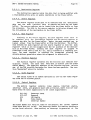
The Sun-1 Workstation consists of two physical units, a display
module and a detached keyboard. The display module contains the video
mOnitor, card cage, power supply, cooling fan, and back panel. The card
cage has seven Multibus slots ••• , two of which are occupied by the processor board and the graphics board.
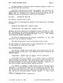
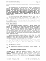
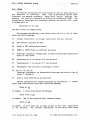
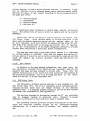
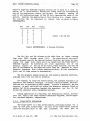
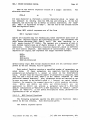
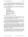
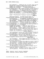
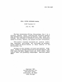
The back panel is illustrated in Figure BACKPANEL. The five connectors labelled "SMD" are used to connect to up to four SMD disk drives
using the optional disk controller. Only the Sun keyboard should be
plugged into the connector labelled "Keyboard". A mouse may be plugged
into the "mouse" connector. The R5-232 serial ports labelled "An and
"B" are used to connect equipment such as terminals, modems, printers,
• Mult1bus is a trademark of Intel Corporation •
•• Lark is a trademark of Control Data Corporation.
••• A small number of the earliest-manufactured units
have six-slot card cages.
V1.0 draft of July 27, 1982
(c) 1982 Sun Hicrosystems, Inc.
SUN-1 SYSTEM REFERENCE MANUAL
Page 2
3HBIT ETHERNET
SERIAL-A
POWER- -ON S\.JITCH
FAN,.
i-lOUSE
FUSE
POWER CORD
o
0
o
0
~~
o
Figure BACKPANEL.
KEYBOARD
0
The Sun Workstation Back Panel.
etc. See the chapter on "Installation" below for information about connecting peripheral equipment to the Sun Workstation.
Be sure to keep the area behind the fan unobstructed.
1.3.
Notations Used in this Document
Integers are normally written in decimal; if preceded by "Ox"
are hexadecimal.
they~
Software interfaces and programming examples are specified in the C
programming language-.
- For a detailed description of C, see Kernighan, B. W.
and
Ritchie, D. M., The C Programming Language,
Prentice-Hall, 1978.
SUN-1 SYSTEM REFERENCE MANUAL
2.
2.1.
Page 3
HARDWARE DESCRIPTION AND CONFIGURATION
Multibus Interface
The Sun-1 Workstation uses two busses: a synchronous, high-speed
memory bus for processor-memory communication and the the IEEE 796 Bus
(Intel l-Iul tibus) for input/output and peripherals. The IEEE 796 Dus is
an asynchronous bus, accomodating devices with various transfer rates
while maintaining maximum throughput. The Multibus provides 8-bit and
16-bit data transfers and 20-bit addressing, extendable to 24-bit
addressing. It allows multiple masters to share the same bus, and provides serial (daisy-chain) as well as parallel priority resolution
schemes. The Multibus has a secondary backplane connector, the P2 connector, for int€e:-module connections. This connector is used in the Sun
workstation for the high-speed memory bus mentioned above.
In order to offer a consistent model for 68000 programmers, the Sun
processor board generates 68000 byte order on the Multibus. This means
that the low-order or the even byte is placed into bits D8 through D15,
whereas the high-order or odd byte is placed into bits DO through D7.
If the processor board communicates with a byte-organized Multibus device, it is typically necessary to reverse the byte-order in software.
The Sun 68000 board generates the 20 address lines on the standard
IEEE 796 Bus. Using these 20 address lines, the board can address up to
one megabyte of memory and one megabyte of input/output locations.
The Sun processor board contains an on-board precision voltage
reference for power-on reset. Multibus INIT is generated whenever the
voltage falls below 4.5 Volt. In addition, Multibus INIT can be generated by executing the 68000 RESET instruction. Note that in this
standard configuration the 68000 always drives INIT to the Multibus and
the 68000 cannot be re~et by an INIT from the Multibus.
If the 68000 accesses the Multibus and does not receive a data
transfer acknowledge within 1 to 3 milliseconds, the access will be
aborted via bus error. The timeout period in the Sun processor board
includes the" Multibus acquisition time. Thus, if a peripheral device
locks up the bus for more than 1 millisecond, timeout can occur.
See also the section titled "Multlbus Priority" below.
For more information about
the
Multibus,
consult
the
following
references:
R. W. Boberg, "796 Microprocessor Bus Standard", Computer, October,
1980.
This publication in the IEEE Computer Magazine
good introduction and overview of the bus.
V1.0 draft of July 27, 1982
gives
a
(c) 1982 Sun Microsystems, Inc.
SUN-1 SYSTEM REFERENCE MANUAL
Page 4
IEEE, nProposed 796-Microprocessor Bus Standard n , with Errata, December,
1981.
This is the official copy of the Standard and includes
date revisions and errata. It is available from:
up-to-
MicroBar, Inc.
Attn: Rich Boberg
1120 San Antonio Rd.
Palo Alto, CA 94303
415-964-2862
Intel Corp., nIntel Multibus Specification n , Revised April 1981.
This is the Intel version of the Standard, recommended in addition to the IEEE version. This document is a superset of
the IEEE standard and contains some application-specific information. It Is available as Manua~ Number 9800683-03 from:
Literature Department
Intel Corporation
3065 Bowers Avenue
Sant~ Clara, CA
95051
408-987-8080
or from local Intel sales offices.
Sun Microsystems, Inc., Sun 796-Bus Interface
~~nua1,
forthcoming.
This document will describe design considerations which apply.
when interfacing other Multibus boards to the Sun Workstation
boards.
2.2.
Processor Board
The Sun processor board contains a Motorola 68000 processor running
with a 10 ~lliz clock, 256 Kbytes of RAM memory with byte parity, an Intel
827~ dual UART (equivalent to NEC7201), an
Am9513 System Timing Controller, and a 16 bit parallel input port. For programming information
on the UART and timer chips, see the manufacturers' data sheets-.
The next chapter on nInsta1lation" provides
installing or removing boards in the Sun-1 card cage.
instructions
for
- Component Data Catalog. Intel Corporation, Santa
Clara, CA.; Am9500 Family Interface Manual, Advanced
Micro Devices, Inc., Sunnyvale, CA.
V1.0 draft of July 27, 1982
. (c) 1982 Sun Microsystems,
-Inc~--'
SUN-1 SYSTEM REFERENCE MANUAL
2.2.1.
Page 5
UARTs
The Intel 8274 or NEe 7201 dual UARTs are wired as follows:
UART A is wired as a DCE port.
on UART
on Connector
Outputs:
TXDA
RXDA
RTSA
CTSA
Inputs:
RXDA
TXDA
CISA
HTSA
DCDA
DTRA
Baud rate: generated by Timer 4.
is wired as a DTE port.
Output:
TXDB
TXDB
I npu t :
RXDB
RXDB
Baud rate: generated by Timer 5.
UART B
2.2.2.
Timers
The AMD 9513 timer chip is configured with an input frequency of 5
MHz and FOUT of 2.5 MHz (connected to Gate 1). It contains five timers,
whose usage is described in the following table:
Timer
1
Usage
Watchdog.
OUT generates
BERR/Reset. [1]
2
User timer.
OUT causes INT6.
3
Refresh timer.
OUT causes INT7.
Operating
Mode
Normal
Frequency
Out=TC,
Repetitive
interval=
2.8 msec
[2]
Out=toggle, repetitive (one
shot). Reset by
refresh routine.
interval=
2 msec
[2]
4
UART A. OUT connected to UART A
TX/RX elk.
Out= toggl e,
repeti tive.
16 times
UART baud
rate
5
UART B.
OUT connected to UART B
TX/RX Clk.
Out=toggle,
repeti tive.
16 times
UART baud
rate
Notes:
[1] Causes reset if Refresh Timer Out (13) is Low.
[2] Difference between timers 1 and 3 determines
Multibus timeout period.
V1.0 draft of July 27, 1982
(0) 1982
Sun Hicrosystems, Inc.
SUN-1 SYSTEM REFERENCE MANUAL
2.2.3.
Page 6
Multibus Priority
The Sun-1 processor board is always configured to be the highestpriority Multibus master, by grounding (asserting) Bus Priority In
(BPRN) on the processor board.
I f the 68000 board is used in conjuntion with a Multibus DMA board,
such as a disk controller, that does not support Common Bus Request
(CBRQ) then the 68000 board must be configured such that it gives up the
Multibus after every Multibus cycle. This also will cause three additional wait states for each Multibus access. The Interphase 2180 disk
controller is an example of a Multibus DMA board requiring this configuration.
On the other hand, if all Multibus DMA devices (Bus Masters) ~
support CBRQ, then the CBRQ jumper on the processor board is not
required. Instead, the 68000 board will retain bus mastership until a
lower priority "master requests it by asserting CBRQ. Following a CBRQ,
the current Bus Master has to yield mastership for at least one cycle.
The CBRQ jumper is the leftmost pair of pins at location J902 on
the processor board, viewing the board with the Multibus at the bottom.
2.3.
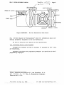
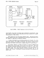
Graphics Board
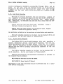
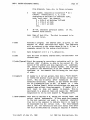
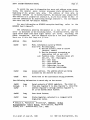
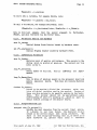
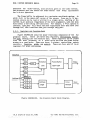
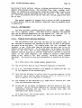
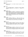
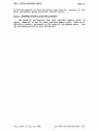
The Sun graphi~ ~ system is a high-resolution bit-mapped frame
buffer and display processor on one Multibus board. The general organization of the graphics board is illustrated in Figure GRAPHICS.
There
is a small amount of hardware assistance to perform a set of simple high
bandwidth operations called "RasterOps". This results in a Simple yet
flexible graphics deVice, with the performance needed to support sophisticated user interfaces. The section below entitled nT-he Sun Graphics~
System" contains detailed speCifications of the programming interface to
the Graphics board.
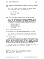
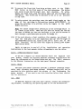
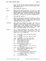
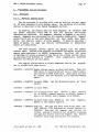
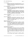
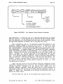
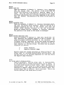
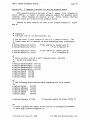
The graphics board has only one switch, which is illustrated in
Figure GBOARD. This switch is used to set the Multibus base address (in
Multibus Memory Space).
It may be set to any address multiple of
Ox20000 between OxO and OxEOOOO.
The standard address for the graphics board is OxCOOOO. Any additional graphics boards are placed at successively lower addresses.
The following table indicates which switch to set for each of the
possible addresses.
Note that ONLY the indicated switch should be
turned on; all other switches should be in the off position.
SUN-1 SYSTEM REFERENCE MANUAL
Page 1
• Bit-Manipu1ation
Hardware
• XIV Addressing
• Graphical Object Cache
• Next Address Generation
Software
• Graphical Object Selection
• Function Selection
Host
RasterOP
,.....
Hardware
Processor
,...
Frame
...,
Buffer
Video
Monitor
AasterOP unit performs read-modify-write cycle
Destination in frame buffer
Source operands can come from frame buffer or host computer
Figure GRAPHICS.
2.4.
address
DIP switch
OxOOOOO
Ox20000
Ox40000
Ox60000
Ox80000
OxAOOOO
OxCOOOO
OxEOOOO
8
7
6
The Sun Graphics Board.
5
4
3
2
(standard setting)
1
Memory Expansion
The Sun memory expansion board provides 768K bytes of additional
"on-board" memory for the Sun processor. It is connected to the processor board via the Mult1bus P2 connector and permits access by the 10MHz
68000 without wait states. Up to two of these board can be added to the
Sun-1 workstation.
The memory expansion board has only one option: to be located
starting at 256K or starting at 1M within the on-board memory address
V1.0 draft of July 21, 1982
(c) 1982 Sun Microsystems, Inc.
Page 8
SUN-1 SYSTEM REFERENCE MANUAL
Multibus
Base Address
C~
1
8
I
Figure
GBOAR~.
Sun Graphics Board.
spac~.
To configure the first memory expansion board to have a starting
address of 256K, insert the 7~S138 chip at location U1006. To configure
the second board for a starting address of 1M, insert the 7~S138 chip at
location Ul008. See the next chapter for installation instructions.
2.5.
Video Display
The video display monitor currently supplied with the Sun-1 Workstation is the Ball Model HD17H CRT Data Display. This is a solidstate, raster-scan, high-density data terminal display with 17 inch
diagonal screen size in a horizontal format. The service manual for
this display is supplied with your workstation:
Service Manual, Ball CRT Data Displays HD Series, 5-017-1047.
This manual provides full specifications and detailed operating and
maintenance instructions for the monitor. Please heed the safety warnings in the manual. Service on the display should be performed only by
qualified service personnel.
2.6.
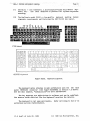
Keyboard
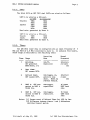
TheSun-1 Workstation is supplied with a detached
able in two configurations (see figure KEYS):
keyboard
avail-
( 1)
The Micro ~>,- itch 103SD30-2, a microcomputer-based Hall Effect keyboard whit.; has been modified to produce full up/down keystroke
encoding.
(2)
The KeyTronic model P2441, a low-profile keyboard meeting German
ergonomic requirements and featuring the DEC VT-100 key layout.
VT100 Kevboard
1035030 Keyboard
Figure KEYS.
Keyboard Layouts.
The keyboard cable attaches to main workstation unit via the back
panel KEYBOARD connector (see figure BACKPANEL in section 1.2 above).
See the next chapter, "Installation" for more information.
The key mappings are table-driven in software and can be redefined.
The section below entitled "The Sun Keyboard" provides the details.
The keyboard is not user-serviceable.
authorized service representative.
V1.0 draft of July 21, 1982
Refer servicing to Sun or an
(c) 1982 Sun Microsystems, Inc.
SUN-1 SYSTEM REFERENCE MANUAL
2.7.
Page 10
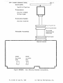
Ethernet Board
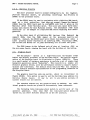
The Sun 3 MBit/sec Ethernet Board provides the connection of the
Sun-1 Workstation to Ethernet-1, the experimental 3 MB~t/sec Ethernet
developed by Xerox PARC. The 3 MEit/sec Ethernet Board interfaces with
the CPU via programmed I/O and interrupt. In Multibus notation, the
board is an I/O slave with 16-bit addressing and 16-bit data paths.
Note that the board is not readily compatible with 8-bit Multibus I/O.
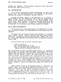
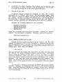
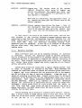
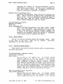
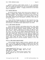
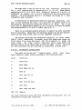
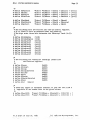
The Ethernet board has two octal dip-switches: one to select the
Mult1bus base address and one to select the local Ethernet host address.
The location of these switches is shown in figure ETHERNET.
The Ethernet interface communicates with the host CPU via four read
and four write registers located in Multibus I/O space. The registers
are located on successive word (16-bit) boundaries starting on a 256byte boundary within the 64K Multibus I/O space. Only the eight highorder address bits are decoded for the selection of the board.
To
select the l-lul ti bus base address, take addre .... s bi ts A8 •• A15 of" the
desired address and encode them into dip-switch S505. Switch #1 1s the
least significant bit, and "1" bits correspond to "on" switches. By
convention, Ox100 is the normal address for the first ~thernet board,
and subsequent boards (if any) are placed at successively higher
addresses.
After obtaining an Ethernet host number from your local Ethernet
administrator, express it in binary and set it into dip-switch S507.
Switch 11 is the least significant bit, and "0" bits correspond to "on"
switches, unlike the correspondence used for the Multibus base address.
NOTE: Ethernet addresses 0 and 0377 (octal) are reserved for special
Ethernet functions and should not be used as a host address.
Two separate documents, providing full specifications and installation instructions, are supplied with the Ethernet board:
SUN 3 MEit Ethernet Board
SUN 3 MEit Ethernet Board Installation Manual
Refer to these for further details.
2.8.
Disk Controller
The Interphase SMD 2180 is an
intelligent
storage
module
controller/formatter, using bipolar microprocessor technology. It plugs
directly into the Multibus and is a Bus Master during data transfers,
using a variable burst length DMA technique. It directly connects via
industry standard A and B cables to from one to four storage module
drives which are available from a number of manufacturers.
Sun
Microsystems supports two such drives in particular: the Control Data
Lark Micro Unit and the Fujitsu M2312K Microdisk Drive. Currently it is
not possible to mix Lark and Fujitsu drives on the same controller
board.
V1.0 draft of July 27, 1982
~ c)
1982 Sun Hicrosy stems, Inc.
. sUN-1 SYSTEM REFERENCE ·-MANUALCoax Cable:
Page
I
11-·
I
I
Type RG11 /U Type Foam
Transceive r:
Xerox Part # 209926
TLC Part # 2000
I
I
Transceiver Cable:
Xerox Part # 216411 D
I 25-pin Typ eO male
11
1
Flatcable Assem bly
25-pin Type 0 female
26- pin cable
(ommitt wire 26)
(3 feet max.)
26- pin header
Ethernet Connector
Multibus
Ethernet
Base Add ress
Host Address
(5505)
(5507)
:0
Figure ETHERNET.
:0
Sun 3 MBit/sec Ethernet installation.
V1 .0 draft of July 27 ,1982
(c) 1982 Sun Microsystems, Inc.
SUN-1 SYSTEM REFERENCE MANUAL
Page 12
You must install at least 6~K bytes of Multibus memory in order
use the SMD 2180 disk controller.
to
Four sets of straps and two a-bit dip-switches are provided for
configuring the disk controller board. For UNIX. on the Sun-1, the M3
jumper must be installed and switch 85 on dip-switch S2 must be ON.
Switches #7 and 8 on dip-switch S1 must be set as follows:
for Lark:
Switches 17 and 8 ON.
for Fujitsu:
Switch 18 ON, #7 OFF.
Switches #1-6 on S1 determine the address of the controller in
I/O space:
Switch 15 ON, others OFF:
address
Switch #5 and 1 ON, others OFF:
Multibus
= Ox~O.
address = Ox44.
Normally, the first controller is configured at Ox40, the next at Ox44.
The controller(s) are normally configured to have lower Multibus priority than the 68000 board, by installing jumper E to F.
See section
2.2.3 above for further explanation.
For the full specification and detailed
controller, see the supplied document:
description
of
the
disk
SMD 2180 Storage Module Controller/Formatter User's Guide.
The next chapter on "Installation" provides instructions for
or removing boards in the Sun-l card cage.
2.9.
install ins
Multlbus Memory
The Chrislin CI-8086 dyn~ic RAM memory bo~rd interf~ces to the Sun
processor through the Multibus. Full specifications can be found in the
supplied manual:
r~mory Systl.,~
CI-808?
Techn~
cal Manual, Chrislin Industries
Each memory board is configured at a chosen range of Multibus
memory addresses by placing a jumper at peg area B on the board and setting dip-SWitches SWl and SW2. See layout drawing 70654 at the back of
the Chrislln manual for the switch and jumper locations. Section 1.4 in
the Chrislin manual specifies memory address selection.
For example, to configure a 128KB Chrislin board at Multibus memory
locations a through Ox1FFFF, pegs B2-3 are jumpered and switches SW1-8
through SW1-5 are closed (set ON), with the remaining switches set OFF.
The second 128K board would have jumper B2-3 and switches SW1-4 through
SW1-1 set ON, for locations Ox20000 through OX3FFFF.
A third board
·UNIX is a Trademark of Bell Laboratories.
V1.0 draft 9f July 27, 1982
~:)
1982 Sun Micros¥stems, Inc.
r __
·~_"
_ _ _ , __ ,
-'SON~l
SYST.EM REFERENCE MANUAL
.- ....
could be configured at Ox40000 by closing SW2-8 through SW2-5, and so
forth.
If you were using the 512K byte boards, all 16 dip-switches
would be set ON; the first board would have jumper B2-3 (axa through
Ox7FFFF) and the next board would have jumper B1-2 (Ox80000 through
OxFFFFF).
2.10.
Lark Disk Subsystem
The Lark is an 8-inch Winchester disk unit providing a maximum of
megabytes of unformatted capacity in the form of an 8.35 ME removable cartridge disk and an 8.35 ME non-removable disk.
BEFORE UNPACKING, INSTALLING, OR OPERATING THE LARK DISK UNIT, PLEASE READ THE SUPPLIED MANUALS:
16.7
Control Data Lark (tm) Micro Unit Model 9454/9455,
(Hardware Installation/Operation V~nual)
Volume
1
Control Data Lark Power Supply and I/O Adapter (PIO), Volume 1
(Hardware Installation/Operation Manual)
Pay particular attention to the sections on installation and operation.
The Lark subsystem connects to the Sun-1 via the standard SMD A and
See the next chapter on "Installation".
B connectors.
2.11.
Fujitsu Disk Subsystem
The Fujitsu M2312 is an 8-inch Winchester disk unit providing a
maximum unformatted storage capacity of 84 megabytes. This unit contains non-removable disks in a sealed module. Since this is a sealed
unit, there is nothing for the user to operate (other than the power-on
. switch) once the drive is properly installed and connected to the Sun
workstatIon.
The Fujj tsu subsyetem connects to tb.e Sun-1 via the standard SMD
and B connectors. See the next chapter on "Installation".
Detailed specifications and maintenance information is provided
the supplied Fujitsu manuals:
A
in
M2311K/M2312K Microdisk Drives CE Manual
M2311K/M2312K Power Supply CE Manual
Maintenance on the disk subsystems should be performed only by a
fied service technician.
V1.0 draft of July 27, 1982
quali-
(c) 1982 Sun Nicrosystems, Inc.
SUN-1 SYSTEM REFERENCE MANUAL
3.
3.1.
Page 14
INSTALLATION
Unpacking Instructions
Inspect all shipping cartons immediately upon receipt for evidence
of damage. If any shipping carton is severely damaged, request that the
carrier's agent be present when the carton is opened. If the carrier's
agent 1s not present when a carton is opened and the contents are found
to be damaged, keep all contents and packing materials for the agent's
inspection.
Carefully unpack all items from the shipping containers.
Avoid
using sharp instruments which may damage the contents. We recommend
that you save salvageable shipping cartons and packing material for
future use 1n case the product must be reshipped.
3.2.
Safety Precautions
Other than procedures described in this document, please do not
attempt to service your Sun-1 work3tation; contact Sun Microsystems or
your field service organization.
Observe common-sense safety precautions as you would for any
electrical or electronic equipment.
Always disconnect power before
opening any system enclosure. Whenever in doubt, contact Sun or an
authorized service representative.
The foIl Ning sections contain set-up and configuration specifications for the Sun-1 Workstation. Consult the additional hardware manuals supplied with your workstation (and with user-supplied Multibus
accessory boards, if any) for further information and precautions.
3.3.
Card
Ca~e
Configuration
The card cage slots are arranged as follows:
TOP
Sun
Sun
Sun
Bus
Bus
memory expansion 2
memory expansion 1
3
processor board
4
master 1
5
master 2
6~
Mul tibus memory, optional (graphics, other)
lL Sun graphics board
1
2
Y
---
' - D)Ul-;. ~
BOTTOM
The earliest-produced Sun systems have a six-slot card cage~
The
arrangement of the six-slot cage is the same as above except that slot 6
contains the graphics board and slot 7 is deleted.
Note that the processor board and Sun memory expansion
V1.0 draft of July 27, 1982
boards
(if
( c) 1982 Sun Hicrosy stems, Inc.
SUN-1 SYSTEM REFERENCE MANUAL
Page 15
any) MUST be located in slots 1,2, or 3, since only these slots have
the P2 edge connectors used by the Sun expansion memory.
"Bus Masters" are Multibus devices which initiate data transfers,
such as the Sun processor board and the Interphase SMD 2180 disk controllers. Bus master(s), if present, must be placed in consecutive
slots immediately below the processor board as shown in the diagram. In
the Sun-1, the processor board is always configured as the highest~; iority
Multibus Master; see section 2.2.3 "Multibus Priority" above
for more information.
A Multibus "Slave" is any Multibus device which does not initiate
data transfers on the bus. This includes the Sun graphics board, the
Sun 3Mhit Ethernet board. Multibus memory boards, serial multiplexer
boards, etc.
After bus masters and Sun memory expansion boards are
positioned as required above, bus slaves may be placed in any empty
slot.
The graphics board is normally placed in the bottom slot to permit easier connection of cables.
3.4.
Removal and Installation of Circuit Cards
Your Sun-1 Workstation is shipped with all cards properly installed
and system tested. If you simply wish to set up and operate the Sun-1
in the conf,iguration that was shipped to you, skip this section and
proceed directly to the section "Set-up" below.
The following steps explain how to remove or install circuit cards
in the Sun-1 Workstation card cage. To avoid damaging the Sun-1, this
work is best performed by someone with prior "hands-on" experience.
If
you have any doubts about any step, please contact your service organization or Sun Microsystems for assistance.
(1)
Disconnect the power cord to the Sun-1.
(2)
Remove tha six screws securing the tray, three on each side of
black SUN-1 pedestal.
(3)
Carefully pull the tray out the back of the pedestal.
it. Gently move cables out of the way as necessary.
(4)
Before removing a card, oarefully note the location and orientation
of all cables attached to it. It may help to mark the flat ribbon
cables with a felt-tipped marker. Note that, on most of the ribbon
cables, pin I' is distinguished by some marking, e.g. the red edge
of the cable. This edge generally faces toward the front of· the
workstation at the point where the cable plugs into a header on the
edge of a cirouit card.
(5)
Before removing any cards, it is necessary to remove the two black
plates (know as ftcard cage restraints") at each end of the PCB
tray. Remove' any cables that are in the way, and extract or insert
the desired card(s). To remove a card, simultaneously lift the two
plastic levers provided for this purpose at each upper corner of
the card.
When inserting a card, make sure that it seats all the
V1.0 draft of July 27, 1982
(c) 1982 Sun
the
Do not force
~~crosystems,
Inc.
SUN-l SYSTEM REFERENCE MANUAL
Page 16
way into the card cage. Pay attention to the position of the cards
in the card cage (see "Card Cage Configuration" above). Observe
that the Multibus edge connectors inside the card cage permit only
one "right way" to install a card.
(6)
If installing a user-supplied Multibus accessory card, follow
manufacturer's instructions for connection of the card. It may be
necessary to route cables around the top or side of the back panel.
In some cases, you may have to leave the tray partially slid out or
cut additional holes in the cabinet. Check with Sun Microsystems
before modifying your workstation to make sure that you will not
invalidate your warranty.
(7)
Slide the processor card back into the Multibus card cage. Do not
force; carefully fold internal cables into the enclosure. After
you are satisfied that the installation is correct, replace the six
screws securing the tray on the sides of the black display pedestal.
(8)
To prepare the Sun-1 for operation, see the section "Set-up" below.
3.5.
Internal Cabling
This section is not a complete specification, but provides some
information on internal cable connections to assist you in properly
reconnecting circuit boards. See the preceding section, "Removal and
Installation of Circuit Boards". For more information on internal cable
connections,. see manufacturers' hardware documentation or consult, a
qualified service technician or Sun ~~crosystems.
The "headers" are connectors on the edge of some of the circuit
boards, which are exposed when the boards are plugged into the Multibus
card cage; i., e., they are on the edge of the board opposi te the Mul ti bus
connector.
Unlike some connectors, these headers allow their matching
connectors to be inserted incorrectly "upside down", so you must take
care to insert them correctly. To accomplish this, the plug should be
inserted into the header so that pin #1 faces toward the front of the
workstation, i.e., toward the video display. The plug itself may have a
distinguishing marking toward one end; if so, this normally identifies
pin 11.
Also, the ribbon cables are usually marked in a highlighting
color along one edge, indicating ·the pin 11 side. To l doubly sure you
can replace a cable correctly, mark it for location and orientation with
a felt-tipped pen before removing it.
The Sun graphics board has one edge-connected cable with six
color-coded wires, connecting it to the (black & white) video display
monitor. The side of the plug where most of the wires are connected is
OPPOSITE to pin 11 and should face inboard, i.e. toward the back of the
workstation. Th~:: pin #1 side of the plug is the side where no wires are
connected and may also have a distinguishing mark on the plug itself;
this side faces forward when plugged in correctly.
~O
the
The processor board has two~pin connectors (headers), one nearer
front of the workstation~ and the other nearer the back of the
Vl.0 draft _ Of July 27, 1982
,,_!c) 1982 Sun
Hicrosystems~
_ Inc.
SUN-1 SYSTEM REFERENCE MANUAL
Page 17
workstation. See Figure BACKPANEL in section 1.2 for identification of
the back panel connectors. The cables from back panel serial ports A
and B merge into a single cable which plugs into the header (on the edge
of the processor board) nearer the front of the workstation. Pin 1 of
the connector, usually highlighted on the connector and/or indicated by
the red edge of the ribbon cable, must face toward the front of the
workstation at the point where it plugs into the processor board.
The
cables from the backpanel keyboard and mouse connectors merge into a
single cable which plugs into the header nearer the back of the workstation.
As above, the highlighted pin 11 side of the connector should
be oriented toward the front of the workstation where it plugs into the
processor board.
The SMD 2180 disk controller board connects internally to the back
panel via industry standard A and B cables. The larger header nearest
the front of the workstation is the A connector; this is connected
directly to the back panel SMD A connector. As usual, the cable plugs
into the header with the highlighted edge (pin 11) toward the front of
the worstation. The four smaller connectors are the B connectors for up
to four storage module drives. Cable number 1 is the farthest forward,
i.e. closest to the A connector; if your workstation is configured for
only one disk drive, the int~rnal B cable for it will be plugged in
there.
Additional drives would take consecutive pOSitions toward the
rear of the controller board. As above, the B cables are inserted with
pin 11 facing the front of the workstation.
The Sun 3 Mbit/sec Ethernet board has one cable connecting it to
the back panel Ethernet connector. This connector, as above, should be
oriented with pin 11 facing toward the front of the workstation.
3.6.
set-up
CAUTION: Before plugging in the power cord of any component of your~
Sun system, be sure that the supplied Volts and Hz are as specified on
the back ~anel of your workstation.
Use only three-prong (grounded)
outlets.
Always remove power before opening any system enclosure or
servicing any system component. All servicing should be performed by
qualified personnel.
The Sun-1 is supplied with a comprehensive set of
nostics. See Chapter 6, "Diagnostics", for details.
ROM-based
diag-
The back panels of the earliest-produced Sun-l Workstations are
unlabeled.
Refer to Figure BACKPANEL in section 1.2 to identify back
panel components.
3.6.1.
Keyboard
The Sun keyboard should be plugged into the connector labeled "Keyboard" on the back panel. If you wish to use the Sun keyboard as your
console input device (as is normally done) you must power-on the workstation AFTER plugging in the keyboard.
See section 4.1 "Getting
Started" for more details.
Vl.0 draft of July 27, 1982
(c) 1982 Sun Microsystems, Inc.
...
Page --18~~:':'
3.6.2.
RS-232 Serial Ports
You may attach a terminal, modem, printer, plotter, or other device
which interfaces through an R3-232 serial port, to one of the serial
port connectors A or B on the back panel.
Note that serial port A provides the CTS, RTS, and DTR control
lines in additj-'n to the transmit and receive l1nes, while port B provides only transmit and receive. This may make line B unsuitable for
connection to devices such as modems which require use of the control
11nes. Consult a hardware technician or Sun if assistance is needed.
Note also that Serial-A 1s a DeE port, which means that you can
connect most terminals or printers directly to this port, while you
probably need to interpose a "null modem". if you wish to connect a
modem or another computer. Serial-B, on the other hand, is a DTE port
which permits direct connection of modems, computers, and the like
(assuming, as noted above, that the control lines are not required)
while requiring a null modem for attaching most terminals. Getting the
cabling right 1s a problem wi· :.ch should be familiar to anyone who has
had to connect RS-232 equipment; sometimes it is most easily solved by
experimentation.
See section 2.2.1 "UARTs" for further specifications.
3.6.3.
Disk Subsystem
Your Sun-1 may have been supplied with either of two optional disk
SUbsystems: the Control Data Lark Module Drive Model 9455, or the
Fujitsu Model M2312 disk drive. Both of these units use the industry
standard SMD interface which is supported by the Interphase SMD 2180
disk controller supplied with your disk subsystem. It is possible to
attach up to four disk drives to a single SMD 2180 controller; however,
at present you cannot mix Lark and Fujitsu drives on the same con-
troller.
The disk subsystem is attached to the Sun Workstation via two flat
ribbon cables.
The (wider) control or "A" cable plugs into the SMD-A
connector on the Sun back panel; the (narrower) data or ffB" cable for
-each of up to four drives plugs into one of the four SMD-B connectors on
the back panel. If two disk controller boards are used, you will have
to route the second set of A and B internal connecting cables around the
top or side of the back panel to bring them outside of the enclosure.
The head assembly of the Fujitsu must be locked during shipment and
should be locked any time the drive is to be moved, even from table to
table. It must be unlocked before the drive can be used. To unlock it
for use, open the disk subsystem enclosure by removing the screws on the
Sides, and follow the directions in section 3.5 of the Fujitsu Microdisk
Drives CE Manual.
• A null modem is an RS-232 cable which reverses pins 2
and 3.
V1.0 draft of July 27, 1982
(c) 1982 Sun Microsystems, Inc.
.
The Fuj~tsu subsystem is very
power cord and an on-off switch.
look through the installation and
manual before using the drive, to
ments and precautions.
- _.-
Page 19
SUN-1 SYSTEM REFERENCE MANUAL
simple to operate, having only a
We suggest that you take some time to
operation sections of the Fujitsu
understand general operating require-
The Lark, with its front-panel controls and removable cartridge, is
more complicated to operate than the Fujitsu. If you have the Lark, we
urge you to read the set-up and operation sections of the Lark manuals
supplied with your system before attempting to use your drive.
Like the Fujitsu, the Lark's head mechanism is locked for shipping
and must be released before use. The manufacturer specifies that the
carriage is to be locked any time the drive is to be moved, even from
table to table. To release the lock, open the disk subsystem enclosure,
and back off the screw labeled "carriage lock" until it is flush with
the top of the top cover on the drive. The lock is set by turning off
power to the drive and turning the locking screw in until it is observed
to engage the carriage mechanism and a slight resistance is felt.
The main rules for operating the Lark are as follows:
(1)
The drive cannot be operated unless a cartridge is installed.
(2)
The cartridge loading door cannot be opened unless power 1s on
the disks are "spun down" (at rest).
(3)
With the power on and a cartridge installed, the disks are made to
spi: up by pressing the START-STOP button on the disk subsystem's
front panel. When the button latches in, the disks will spin up.
While they are spinning up, the green light on the START-STOP button will flash and the disks will not yet be usable by the Sun-l.
When the green light burns steadily (a few minutes after preSSing
START-STOP) the disk is ready to use.
(4)
The disks are made to spin down by pressing the start-stop button
again to return it to the "out" position. The green light flashes
while the disks are spinning down. The cartridge door cannot be
opened until the disks are completely spun down, as indicated by
the green light going out. This takes about a minute.
(5)
When power is on and the disks are ft lly spun down, the cartridge
door can be opened by squeezing upward on the latch button located
in the top of the indentation in the door.
(6)
After opening the door, you can eject the cartridge by pushing down
firmly on the open door.
Always keep the door closed when the
drive is not in use. The manufacturer recommends keeping a spare
unused cartridge in the drive when it is not in use.
(7)
When loading a cartridge, be sure to insert it so that the arrows
labeled UP/IN are facing up and pointing into the disk drive,
respectively.
V1.0 draft of July 27, 1982
AND
(c) 1982 Sun Microsystems, Inc.
SUN-1 SYSTEM REFERENCE MANUAL
Page 20
(8)
To prevent the fixed disk from being written, push in the FlXEDPROT button on the front pa~el of the disk subsystem. The button
will latch in and the red light will burn steadily.
To writeenable the fixed disk, push the button again and the red light will
extinguish. This button may be switched to the in or out position
at any time.
(9)
To write-protect the cartridge, move the small black toggle on the
edge of the cartridge to the position labeled WRITE PROTECT. To
allow the cartridge to be written, slide the toggle to the WRITE
ENABLE position.
NOTE: You cannot change write protection on the cartridge while it
1s loaded in the drive. Hake sure you have the switch set the way
you want it BEFORE you load the cartridge, or you will be forced to
wait through a spin-down/spin-up cycle to change it.
(10) If the Lark detects a fault condition (for example, you attempt
to
read the disk when it is not completely spun up) the red light in
the FIXED-PROT button will flash on and off to alert you to the
error condition. You can clear this signal by pressing the FIXEDPROT button twice.
Again, we urge you to read all of the installation and operation
instructions in the Lark manuals before attempting to use the drive.
3.6.4.
3 Mbit/sec Ethernet.Board
If the Sun 3 megabit per second Ethernet board was supplied with
your system, consult the separate Ethernet documents supplied with the
board for information on its installation and use. The Sun-l connects
to the Ethernet transceiver via the back panel Ethernet connector.
3.6.5.
Mouse
The back panel Mouse connector provides a hardware interface compatible with currently used mouse devices. Software support will not be
provided for this interface until the release of the forthcoming Sun
mouse product.
If you need to use this interface before then, contact
Sun for assistance.
3.7.
UNIX
If UNIX was supplied with your Sun-1 system, consult the accompanying document, "Installing and Operating UNIX on the Sun Workstation".
V1.0 draft of July 27, 1982
(c) 1982 Sun }Vlicrosy~t~ms, _ Inc.
SUN-:-1 SYS!El-f REFERENCE MANUAL
4.
Page 21
USING THE SUN PROCESSOR
4.1.
Getting Started
After the Sun-1 Workstation has been properly installed (see the
preceding chapter), the workstation and disk sUbsystem (if present) can
be powered on. The "ON" position of the back panel power switch is to
the left as you face the back panel.
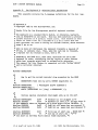
After a few seconds, the monitor should identify itself on the console terminal, with a message looking like
Sun Workstation Monitor (Rev. C) - Ox100000 bytes of memory
If this t.t1essage does not appear, and repeated use of the Power switch
has no effect, make sure that power is being supplied from the outlet
and that the Sun's fuse 1s not burned out. If you still have no success, consult chapter 6 for recommended diagnostic procedures, or contact your Sun Hicrosystems service organization.
If the console displays the message
Please clear keyboard to begin
above the Sun Monitor message, and the system doesn't respond to input
from the keyboard, the likelihood is that one of the latching keys (CAPS
LOCK or SHIFT LOCK) is latched in the down POf' ::.ion, which prevents the
keyboard from sending an idle signal to the monitor. Releasing all
latched keys should solve the problem; if not, check the keyboard cable
and connector to make sure that a proper connection exists. If the connection appears sound, try powering the workstation off and on again.
If the problem persists, there is probably a defect in the keyboard or
keyboard cable. Contact your service organization or Sun for assistance.
On the Sun keyboards, holding down the upper-left-most key (ERASEEOF on the Micro Switch 103SD30) and typing an "a" causes a trap (also
known as an "Abort") to the monitor so that debugging commands may be
given.
If the console device is an ASCII terminal connected to one of
the UARTs (see the U command, described under "The ROM Monitor Commands"
below), an abort is generated by pressing and releasing the "Break" key.
You may continue an aborted program; see the C command, described below.
_.2.
UNIX
If your Sun-1 is supplied with the UNIX operating system, the first
thing you will typically do after powering-up the system is to initiate
("boot") UNIX using the monitor's Boot command. After booting, most of
your interaction with the Sun-1 will be with UNIX rather than directly
with the ROM monitor. To get started, see the accompanying document
titled "Installing and Operating UNIX on the Sun Workstation". A complete reference on UNIX 1s provided in the UNIX Programmer's Manual,
also suppli.ed.
After you have familiarized yourself with the features
of·UNIX on the Sun, we suggest that you return to this chapter and scan
V1.0 draft of July 21, 1982
(c) 1982 Sun Hicrosystems, Inc.
SUN-1 SYSTEM REFERENCE MANUAL
Page 22
through the remainder of this document, studying in detail only those
sections that appear useful to you.
~.3.
The ROM Moritor
Use of the Sun-1 Workstation involves interacting, at least initially, with the ROM-resident monitor. The remainder of this chapter
discusses the purpose of the monitor, and how to use it.
Although the primary function of the ROM monitor is to provide a
simple console for the workstation, there are a few features which
affect the user programs that run under it. For simple programs, especially those using standard I/O routines, the characteristics of the
monitor should not be important. However, if a program makes direct use
of interrupts or I/O devices, a few critical details are relevant.
4.3.1.
What is the monitor?
We will first give a brief description of the operation of t~e monitor, to provide a context for understanding the rules imposed upon user
programs.
The monitor has four major functions: initialization on processor
reset, memory refresh, terminal emulation, and "intelligent console"
facilities. Although the last two may be the most visible, the first
two are the most important; the processor would be essentially unusable
without them.
The Sun processor may be "reset" in several ways:
- Power is turned on.
- By a console command (K1 or K2).
- When the "watchdog timer" detects that no
memory refresh has occurred within 6 ms.
When the processor is reset, the monitor gains control. It initializes
the on-board I/O devices (timers and UARTs), sizes memory, sets up the
Segment Table and Page Table, initializes the on-board RAM to all ones,
creates the RAM refresh routine, and initializes the interrupt and
exception vectors and the mom tor's RAl-'i-· "esident global data. The monitor checks for the presence of a second PROM pair in the second set of
CPU board PROM slots. The second PROM pair contains the Boot routine
(inVOked by the B monitor command) and a diagnostic routine which is
automatically invoked on non-watchdog resets. After initialization, the
monitor transfers control to a module that manages the nconsole" functions.
Memory refresh is done by the processor because it simplifies the
hardware while not incurring any Significant performance penal t..-. The
memory is refres~ed by simply reading 128 consecutive words ever· ) milliseconds.
The reads are done as instruction fetches by executing a
routine consisting mostly of NOPs. This routine is stored in RAM, and
so a malfunctioning program may damage it and thus cause havoc. The
watchdog timer will detect this and reset the system within 6 IDS.
It
Vl.0 draft of July 27, 1982
(c) 1982 Sun Microsystems, Inc.
~~
....
~
_
•• 4
•..
_____
_
-'SUN-1 .'SYSTEM
REFERENCE" MANUAL
Page 23
restores the refresh function and allows memory to be examined for diagnosis.
The console functions are implemented with fairly straightforward
routines that communicate with the user via the Sun keyboard and
display. If the keyboard is unavailable upon reset, the monitor will
use UART A for input, which may be connected to a standard ASCII terminal. If the frame buffer (graphics board) is unavailable, UART A will
be used for output as well. These default assignments of input and output device may be changed via the "un command.
See "The ROM Monitor
Commands" below.
All monitor I/O is done using "busy-waits", and the code runs at
the highest interrupt priority. Therefore, if a user program 1s interrupted by typing the Abort sequence on the console terminal or with some
other exception, the monitor will run correctly unless its global data
area has been damaged. If the user program is then continued, it should
be unaffected by the interruption save for the possible loss of some
console I/O interrupts.
4.3.2.
Absolute Rules
The first 16K bytes of memory (addresses 0 through Ox3FFF) are
reserved for the monitor and ~hould never be written by user programs;
however, user code may want to change exception vectors occasionally.
It is legal to change any exception vector, except the following: the
"Level 7 Autovector" at Ox7C (used for refresh timing), or any "User
Interrupt Vector", between Ox100 and Ox3FF, inclusive. The refresh routine and monitor globals .i.ive in the region reserved for "User Interrupt
Vectors", because the Sun processor board hardware does not permit their
use as interrupt v€~tors.
Certain other exception vectors (Trace
Ox24, Trap 11
Ox84
(Breakpoint Trap), and Trap 114 - OxE8 (exit to monitor» are used by
the monitor. '!'hese may be altered without dire results, although the
corresponding monitor facilities would not be available.
Any program altering the refresh routine or its interrupt vector
must take responsibility for doing proper memory refresh and resetting
the refresh and watchdog timers. See section "Watchdog Timer" below for
more details.
4.4.
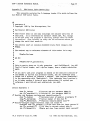
The ROM Monitor Commands
The command format understood by the monitor is quite
Simple.
It
18:
<verb><space>-[<argument>]<return>
The <verb> part is always one alphabetic character; case does not
matter.
<Space>- means that any number of spaces is skipped here.
<Argument> is normally a hexadecimal number or a single letter; again,
case does not matter. Square brackets n[ ]" indicate that the argument
portion may be optional. When typing commands, <backspace> and <delete>
V1.0 draft of July 27, 1982
(c) 1982 Sun Microsystems, Inc.
SUN-1 SYSTEM REFERENCE MANUAL
Page 24
(also called <rubout> , generated by the key labelled <back-tab> on the
current Sun keyboard) erase one character; control-U erase3 the entire
line. <Return> means that you should hit the carriage return key.
Several of the commands open a memory word, map register, or processor register.
This causes the address or register name to be
displayed along with its current contents. You may then type a new hexadecimal value, or simply <return> to go on the next address or register. Typing Q will get you back to command level.
For registers,
"next" means within the sequence DO-D7, AO-A6, SS, US, SR, PC. For
example, the following commands set location 1234 to 5678, and register
D1 to OFOO.
The user types the underlined parts, with a return a the
end of each command.
>e 1234
001234: 23CF?
001236: OOOO?
>d
DO: 00000001?
D1: 00000231?
D2: 01203405?
5678
q
Of00
q
>
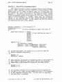
The commands are:
A n
Open A-register n (0 < n < 6, default 0).
cussion above of "open".
See the
dis-
B [dv(u,p)name] Boot.
Calls the boot routine, which is located at the
beginning of the second pair of eproms on the processor
board. Each of the arguments
and
dv
(u,p)
name
is optional; they default to "dk", "(0,2)", and "unix"
respectively.
For example, if you simply type "b", the
command defaults to
B dk(0,2)unix
which is the standard UNIX boot. Similarly, if you type
"b diag", the command defaults to
B dk(0,2)diag
The parameters dv, u, p, and name are passed to the boot
routine, which interprets them as follows:
dv
A two-character string which identifies the
boot device. Currently only "dk" (disk) is
recognized. This will be extended for booting
V1.0 draft of July 21, 1982
- SUNr'':'l SYSTEM-REFERENCE
MANUAL
Page 25
from Ethernet, tape, etc. in future releases.
U
Unit number, computed as (controller I 8) +
(drive). Controllers 0, 1, 2, 3 are
configured at Multibus I/O addresses Ox40,
Ox~4, Ox48, Ox4c.
For example,
o = drive 0 at Multibus I/O Ox40
8 = drive 0 at Ox44
9 = «'ive 1 at Ox44
etc.
P
If <16, indicates partition number.
denotes block offset.
name
Name of boot file.
If >16,
The disk is assumed to be
in UNIX format.
C addr
Continue a program. The address addr, if given, is the
address at which execution will begin. The registers
will be restored to the values shown by the A, D, and R
commands, except for the system stack pointer.
D n
Open D-register n (0
E addr
Open the word at memory address addr; odd addresses
rounded down.
< n < 7,
default 0).
are
G [addr][param] Start the program by executing a subroutine call to the
address addr if given, 01' else to the current PC. The
values of the address and data registers are undefined;
the status register will contain Ox2700. One parameter
is passed to the subroutine; it is the address of the
remainder of the command line following the last digit
of addr.
K [number]
If number is 0 (or not given), this does a nSoft Reset":
it resets the monitor stack and the default escape character. This can be useful after exceptions or other
anomalous situations. However, it may confuse the monitor if a breakpoint trap is set. If number is 1 this
does a "Medium Reset-, which ~e-in1tializes the page and
segment maps without clearing memory. If number is 2, a
hard reset is done and memory is cleared. This is
equivalent to a power-on reset and causes the ROM-based
diagnostics to be run (see chapter 6, "Diagnostics").
L Host-command
This does an impliCit U B, saving the current input and
output device aSSignments. It then sends Host-command
to the host computer, and sends a backslash character
(hex 5c) to the computer to indicate that it is ready to
be downloaded via the serial line.
The Host-command
should put the workstation back into normal mode after
the file is downloaded by issuing an explicit U command,
V1.0 draft of July 27, 1982
(c) 1982 Sun Microsystems, Inc.
Page 26
SUN-1 SYSTEM REFERENCE MANUAL
which will restore the previous assignment of input .and
output device. For more details, see the section "Loading Programs" below.
Mm
Opens Segment Map register m.
o addr
Opens the byte location specified. The byte vs. word
distinction can be a problem on the Multibus, since some
Multibus boards follow the 8086 convention for byte ordering within words, which is the reverse of the 68000
convention. See section 2.1 above for further details.
P P
Opens Page Map register p.
R
Opens the miscellaneous registers (in order) SS (Supervisor Stack Pointer), US (User Stack Pointer), SR
(Status Register), and PC (Program counter).
Alterations made to SS will have no effect.
S S-record
This causes the moDi tor to accept
the
S-rec;"<'d,
described in section "S-record Format" below. Normally
received from the host computer in L mode (see the L
command above), this responds with a two-digit record
count followed by a single letter, either L for length
error, K for checksum error, or Y for success.
U [arg]
The U command manipulates the on-board UARTs
and
switches the current input or output device. The argument may have the following values ("{ab}" means that
either "a" or nb n is specified):
lab}
Select UART a (or b) as input and output
device
{ab}io Select UART a (or b) as input and output
device
{ab}i
Select UART a (or b) for input only
{ab}o
Select UART a (or b) for output only
Select keyboard for input
k
Select keyboard for input
ki
Select screen for output
s
Select screen for output
so
ks, sk Select keyboard for input and
screen for output
Set speed of UART a (or b) to D (such as
lab},
1200, 9600, ••• )
{ab}t
Enter transparent mode with UART a (or b)
t
Enter transparent mode with UART b
Echo input to output
e
ne
Don't echo input to output
x<char> Set the transparent mode escape character
to <char>; initially AA (hex 1e).
Use automatic flow co·'trol ("'S/AQ) in
f
transparent mode
nf
Don't use flow control
V1.0 draft of July 27, 1982
,,(c)
"-
~982.
Sun
M~cr,o~Y,stemsL}:nc.
If no argument is specified, the U command reports the
current values of the settings. If no UART is specified
when changing speeds, the "current" input device is
changed.
When received from the host computer in L mode (see the
L command above), the U command causes the mOnitor to
stop taking input from the host computer and restores
the previous assignment of input and output device. In
this case the argument, if present, is ignored.
Z ~addr]
~.5.
Display or set the breakpoint. If addr is omitted, the
breakpoint 1s displayed.
If an address of zero 1s
specified, the breakpoint is removed.
Otherwise, the
breakpoint is set to the given address.
Loading Programs
One of the primary uses of the moni to is to load programs into the
processor's memory. Programs can be loaded via a serial line connected
to a host computer, referred to as "down-line loading".
4.5.1.
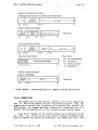
8-record Format
Down-line loading involves
serial line.
The ,"lie must
records" before transillission.
transferring a program file over a
be converted into a format known as "S-
In response to the L command, the monitor prepares to receive a
sequence of 3-records from the host computer, followed by a U command to
return the monitor to interaction witb the user.
An S-record is the standard Motorola
Each S-record has seven components:
EXORCISOR-
download
format.
1.
The letter S.
2.
A type, a single digit either 2 (signifying a Data record) or 8
Trailer record).
3.
A two digit (one byte) count between 04 and FF, giving the total
number of bytes 1n the address, data, and checksum (items 4, 5, and
(a
6).
4.
A three-byte address (six hex digits).
5.
n-4 bytes of data, where n 1s the count given in 3.
sists of two hex digits from 00 to FF •
Each byte con-
• EXORCISOR is a trademark of Motorola Inc.
V1.0 draft of July 27, 1982
(c) 1982 Sun Microsystems, Inc.
SUN-l SYSTEM REFERENCE MANUAL
Page 28
6.
A one-byte (two dig1 t) checksum. The checksum' ~~st 1s that the sum
of the bytes in items 3 through 6 must be congruent to 255 mod 256,
1.e. must have (hex) FF in the least significant byte.
7.
The end of the line.
A complete download consists of a sequence of data (52) records
terminated by a trailer (S8) record. The trailer must appear. Each
data record is loaded into memory starting with the address specified in
the record, provided it passes the checksum test. The trailer serves
two functions: to terminate loading, and to load PC with the trailer's
address, giving a mechanism for defining the entry point of a program.
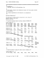
Consider the following sequence of four 5-records:
S2080d3144190031f03b
S2080d31483310ca055f
S2080d314cOOOOl12339
SB040d314A73
These four S-records load twelve bytes into memo:" '? starting at location
Oxd3144. The starting PC is Oxd314A. The byt~s ~hich ru'e loaded are:
190031f033100a0500001123
4.5.2.
Example of Down-line Lo:-,ding
Suppose the file we want to load is oalled test.dl and the host
command to download a file is "dlx <filename>". Assuming that you have
used "transparent" mode to log into the host computer and initialize its
command environment appropriately, you should then "escape" from transparent mode. Then, issue the command
L dlx test.dl
This will transmit the command ndlx test.dl" to the host, and then cause
the monitor to accept subsequent commands from the host. The monitor
sends a backslash character to the host ~. an it 1s ready to begin
receiving S-records.
When the down-load is complete, the host should
send a nun monitor command, switching monitor input back to the console
keyboard.
You can then start your program with the G command. Normally, the current PC will have been set by the downloader to be the
entry point of the program; if not, you can specify a starting address
with G.
You can abort a download by hitting the nBreak n key on the oonsole
terminal, changing to transparent mode via "U t", and interrupting the
host. Down-line loading a file not in S-record format will probably
cause strange behavior, therefore the host program should check the data
it 1s downloading.
V1.0 draft of July 27, 1982
.~
c) 1982 Sun Microsystems, Inc.
SUN-1- SYSTEM ~REFERENCE MANUAL
4.6.
Traps
The monitor initializes the trap vectors so that it gets control of
any exception or interrupt.
Some, such as the memory refresh timer
interrupt, are handled internally. Others have special meanings (for
example, the "trap 11" operation is treated as a breakpoint trap). For
exceptions or interrupts not internally handled, the monitor will print
a message such as
Exception: Tr at <pc)
and then return to command level.
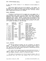
The messages printed use a two-letter code; here is a list of these
codes and their meanings.
II
Illegal Instruction: an illegal instruction code was executed
ZD
Zero Divide: division by zero
Ch
Check: a CHK instruction faulted
TV
TRAPV: a TRAPV (trap on overflow) was taken
Pr
Privilege violation: attempt made to execute privileged instruction
while in user state
UO
Unimplemented 0: an opcode 1010 was executed
U1
Uni~plemented
Un
Unassigned: trap was made to
1: an opcode 1111 was executed
unassign(~d
vector.
Ll, L2, L3, L4, L5, L6
Interrupt A'.1tovector: an Autovectored interrupt was taken at one of
levels 1 through 6.
Tr
Trap: a trap instruction was executed.
Several exceptions are handled specially by the monitor.
point trap (instruction. "trap 11") causes the message
A break-
Break at E£.
to appear.
A trace trap evokes the message
Trace trap at
to appear.
~
Use of the keyboard abort sequence causes
Abort at
~
to appear. In each case, the pc shown is that of the next instruction
to be executed.
For further information on the use of these three
V1.0 draft of July 27, 1982
(c) 1982 Sun Microsystems, Inc.
SUN-1 SYSTEM REFERENCE MANUAL
Page 30
traps, see section 4.7. "Tracing Programs".
An Address Error trap (caused by attempting to access a
an odd address) causes the monitor to print
word
with
Address Error: address <access-address> at <pc).
There is a class of errors that may cause the processor to take a
In the case of either an Address Error or a Bus
Bus Error exception.
Error, the <access-address> is useful in helping to determine the cause
of the trap.
Besides the access address, the monitor saves various
information that may be useful for diagnosis. This is discussed in the
next section, "Bus/Address Error Traps". It is possible to continue
from these traps, although the apparent effect of the faulting instruction is not always predictable.
The monitor intercepts bus error exceptions and, by examining a
wide variety of processor state components, classifies these errors
according to the following scheme:
Protection Error
A reference was made to the <access-address> (see below) which is
not allowed by the segment map for the access mode in effect at the
time of the trap. For example, a program tried to write to a segment mapped read-only.
(Note that the monitor always runs in
supervisor mode, even after a trap from user mode.)
- System Space Error
A reference was made in user mode outside of the space mappable
the segment map (i.e., the address was above Ox1FFFFF).
b~
- Page Invalid Error
A reference was made to a page which was not valid (that is, the
page was not mapped to one of on-board memory, Multibus memory
space, or Multibus I/O space.)
- Timeout Error
A Multibus reference timed out; usually, this means that a device
or memory was referenced but is not plugged into the card cage, or
is not working right.
- Pari ty Error
The wrong parity was seen on a read from on-board memory.
- Watchdog Error
The watchdog timer expired and caused a bus error.
For any of these errors, the monitor prints a message such as
Protection Error: address <access-address> at <pc>
~~.c) ~1-98'2
j':'--~ .-~
-Sun
l-1icrosY)3~:~ms,
-' - .-.-:....
--
Inc.
~
.--~.
- ..... --
.....
-.-.
,;.~.,'.~.
~ -
... ~-
.
.:..-~-
-
SON-1 SYSTEM REFERENCE MANUAL
Page 31
To assist the user in diagnosing bus error and address error exceptions, the monitor saves various processor state information at the
beginning of its global data area.
The address of this area is
currently defined to be Ox200j however, the monitor will always store
this address as a longword at location 0, so you will always be able to
find the information by 1ndirecting through location O. You can examine
this data with the "E" monitor command.
For more information on MC68000 exception handling,
MC68000 User's Manual*.
refer
to
the
The information saved by the mOnitor on a bus error or address
error is described in the following table. On address errors, only the
first three items (the first eight bytes) are saved.
Following the
68000 conventions, bits are numbered with bit a the least significant.
Words are 16 bits and longs are 32 bits.
Address
Size
Description
Ox200
word
Misc. information saved by 68000:
Bj.ts 15-5: Not mearu.ngful.
4: Was the access a read or write?
(write=O, read=1)
3: Was the processor processing an
instruction (=0) or not (=1)?
2-0: Function code. Possible values are
000, all, laO - Unassigned.
001 - User Data
ala - User Program
101 - Supervisor Data
110 - Supervisor Prci;ram
111 - Interrupt Acknowledge
Ox202
long
Access address. The address which was being
accessed by the aborted bus cycle.
Ox206
word
First word of the instruction being processed.
The following information is saved only on bus errors:
Ox208
long
x 16
Saved contents of 68000 registers. The order is
from data register a to data register 7, then from
address register 0 through address register 7.
A7 is the System Stack Pointer.
Ox248
long
User Stack Pointer.
Ox24C
long
Status Register, extended to a longword with
high-order zeros •
through
Ox247
• Section 5, "Exception Processing", MC6800o: 16-Bit
Microproces:!.O£ User's Manual, Third Ed1 tion, Englewood
Cliffs, N.Jh: Prentice-Hall, Inc., 1982.
V1.0 draft of July 27, 1982
(c) 1982 Sun
~licrosystems,
Inc.
SUN-1 SYSTEM REFERENCE MANUAL
Ox250
long
Page 32
Program Counter. The value saved is advanced an
unpredictable amount, from two to ten bytes beyond
the address of the first word of the instruction
which made the reference causing the bus error.
Note that the registers saved in locations Ox208 through Ox253 are in
exactly the same order and format in which they are displayed when )'ou
type the "Dn command to the mOnitor, then keep hitting RETURN.
4.6.2.
Watchdog Timer
On the Sun processor board, one of the five on-board timers
nected so that if it ever goes off, the "Reset" line is asserted
processor is restarted as if the power had just come on.
The
attempts to prevent this by recycling the timer each time
through its memory refresh routine.
1s con-
and the
monitor
it goes
However, if the processor halts, or if the memory refresh is not
done (because the interrupt vector or refresh routine was altered), this
"watchdog" timer goes off and resets the processor. Otherwise, it would
hang and its dynamic memory contents would be lost.
If the processor suddenly displays its restart message, you should
assume that your program either halted or destroyed some monitorspecific data. It is also possible that a hardware failure is to blame.
Note that in many cases it is pos·tble for the monitor to detect
the difference between a true restart and a watchdog timer restart. It
avoids clearing memory, and displays "Watchdogl" before the usual "Sun
Workstation M9nitor" message.
4.7.
Tracing programs
The monitor provides several facilities for tracing program execu~
tiona
They are quite primitive, however, and basically require you to
understand your program at the machine code level. However, if you have
a symbol table listing of your program, you will be able to at least
know where each routine starts.
4.7.1.
Breakpoint traps
The use of a Breakpoint trap (BPT) allows to run a program and
regain control when execution reaches a certain location. The monitor
currently can only maintain one breakpoint trap at a time. A breakpoint
trap is set at address A. by typing B x. The current breakpoint aodress
may be queried by typing B alone. The current breakpoint may be cancelled by typing B O.
You can then start or resume your program with the C (or possibly
G) command. Execution will proceed until the trap is reached, at which
point you will get a message such as
Break at 001000
V1.0 draft of July 27,1982
(c) 1982 Sun Hicrosystems, Inc.
SUN-l SYSTEM REFERENCE MANU-AL
Page 33
At this point, you may examine registers, memory, etc.
You may also
clear the BPT or set a new one. You may continue using the C command,
which will execute the nbroken" instruction, and ] .. ave the breakpoint
still set.
If you load a new program while a BPT is set, the monitor will normally be able to detect this. On the other hand, if you give the Kl
command ("Medium Reset") while a BPT is set, and then set a new one, the
monitor will be confused if the first trap is taken.
4.1.2.
Trace traps
Support for Trace traps (single-stepping a user program) is
minimal.
To set a trace trap, you should use the R command, proceed to
the Status Register (SR), and alter it so as to inclusive-OR it with
Ox8000. Similarly, the trace trap can be cleared by ANDing the value of
SR with Ox7FFF.
Once the trace bit is set in the SR, you should then give the C
command to continue the program (the G command cannot be used, since it
doesn't restore the SR~; to start a pro~'am with the trace bit set, give
the command C <starting-address>.
After each instruction is executed, the message
Trace Trap at <pc)
appears, where <pc> indicates the address of the next instruction to be
executed.
If you hit Return right after this message appears, the next
instruction will be executed. If you enter any other commands, you must
use the C command to continue.
V1.0 draft of July 27, 1982
(c) 1982 Sun Microsystems, Inc.
SUN-1 SYSTEM REFERENCE MANUAL
~~OGRAMMING
5.1.
5.1.1.
Page 34
THE SUN PROCESSOR
Processor
Physical Address Space
The Sun processor is provided with a map so that you can map pages
of 2K bytes anywhere in your address space. The structure of a virtual
address is described in the Memory Management section.
On power-up, the monitor maps the first megabyte of on-board RAM
and memory expansion board RAM so that its physical and virtual
addresses are identical. All segments, starting at segment 0, are fully
mapped. Segments, are initialized for all contexts identically. Segment
protection is set' so that both Supervisor and User modes have Read,
Write, and Execute access to every segment. If there is less than 1
Mbyte of memory, pIl page map entries corresponding to nonexistent
memory are invalidated.
Two other physical address spaces are mapped into the memory
address space. Address from Ox100000 to Ox1EFFFF are mapped to Multibus
memory space addresses 0 to OEFFFF, respectively. The first 64K bytes
of MultiBus I/O space is mapped at the top of the virtual address space,
at addresses from Ox1FOOOO to Ox1FFFFF.
Most commercially available
Multibus I/O devices use this space.
The logical address space of 24-bit addresses used by the
mer is divided into eight parts:
program-
OxOOOOOD - Ox1FFFFF Mapped address space, as described above. There are
256K bytes of on-board RAM and up to 2 memory expansion boards of 768K bytes each. This space can also
be mapped into the Multibus I/O or Multibus Memory'
space.
Ox200DOO - Ox3FFFFF On board PROMO.
state".
See the discussion below
on
"boot
Ox400000 - Ox5FFFFF On board PROM1.
Ox600000 - OX7FFFFF The on-board double UART. Channel A data register
is at 600000, command register at 600002, Channel B
data is at 600004, and B command is at 600006.
Ox800000 - Ox9FFFFF On board Timer chip. 800000 is the
800002 is the Command register.
Data
register,
OxAOOODO - OxBFFFFF Page map. The page map entry used to map some virtual address X is addressed at virtual address X +
OxAOOOOO. Note that the segment map entries for
virtual address X should be set up before accessing
the page map entries since the segment map entries
determine which page map entries are accessed.
V1 .0_ ,draft or J\lly 27 t 1982
:( q) 1982 Sun
Micr9.systems, ," Inc.
SUN-1 SYSTEM REFERENCE- MANUAL-
OxCOOOOO - OxDFFFFF Segment map.
The current value of the context
register determines which group of segment map
entries are addressed. The segment map entry used
to map some virtual address X is addressed at virtual address X + OxCOOOOO.
When read as a short-word, the high-order 4 bits of
any segment map entry give the current value of the
context register.
OxEOOOOO - OxFFFFFF Context register when written (the high 4 bits of
the shortword.) When read, this returns the 20-bit
v~ue of the parallel input port; the
monitor uses
this input port for the keyboard and pointing device.
In "boot state", the state of the system after reset, read and execute accesses to any location OxOzzzzz in mapped addresss space are
redirected to come from the corresponding location Ox2zzzzz (in the
PROMO address space), but write accesses to the mapped address space go
to on board RAM.
Also, all interrupts (including normally "nonmaskable" ones) are inhibited. In this way it is possible to initialize
RAM just after reset. Boot state is exited by writing to the PROMO
address space.
5.1.2.
Exception Handling
When a processor cycle can not be completed normally an exception
is performed.
Besides the exceptions caused by internal conditions,
such as divide-by-O or word-access to an odd-byte address, five external
conditions can make it impossible to complete the current j,nstruction or
bus cycle. These external conditions which raise a Bus Error exception
are: system space errors, segment map errors, page map errors, timeout
errors, and parity errors.
System space errors are caused when a logical address greater than
or equal to Ox200000 is accessed in user mode. These addresses are
reserved for supervisor state to address the on-board system facilities.
A segment map error indicates that the protection bits in the segment
map did not allow the type of operation attempted. A page map error is
caused by accessing an invalid page. Timeout errors occur for off-board
references to the Multibus that are not acknowledged within one to three
milliseconds.
Most likely, nonexistent memory or a nonexistent device
has been addressed. (There are no timeouts for on-board references
because the on-board bus is synchronous and all cycles are always acknowledged.) Parity errors occur if a byte or word with odd parity is
read from local RAM. Since parity can only be checked at the end of a
memory read cycle, the 68000 cannot abort the cycle in which the error
occured, but the next cycle.
Parity checking can be enabled or disabled under software control.
When a write is done to PROMO address space to exit boot state, the low
order bit of the data written controls whether parity checking is done.
If the low bit is a 1, parity checking is enabled, otherwise is 1s
V1.0 draft of July 27, 1982
(c) 1982 Sun Microsystems, Inc.
SUN-1 SYSTEM REFERENCE MANUAL
disabled.
Page 36
Such a write may be done at any time (from supervisor state).
When a bus error occurs the cause of the error can be determined by
checking whether the attempted access was to system space in user mode,
whether a mapped access violated the segment protection code, or whether
the page referenced was nonexistent. If none of the above caused the
exception, then the exception was a timeout for bus accesses, or a parity error caused by local accesses in the previous memory cycle.
5.1.3.
Interrupts
The 68000 bas seven interrupt levels, numbered 1 through 7, with
level 7 being the highest priority and level 1 the lowest priority.
Interrupts are recognized for all priority levels greater the the
current processor priority level contained in the 68000 status register.
When an interrupt is acknowledged the processor priority is set to the
level of the interrupt request.
A level 7 interrupt is special in that it is recognized even if the
mask in the 68000' s status register is set to 7, thus providJng a nonmaskable interrupt capability. A level 7 interrupt is acknowledged
every time the interrupt request changes from a lower level to level 7,
that is, level 7 interrupts are "edge-triggered".
The Multibus standard defines 8 interrupt lines, INTO through INT7,
with INTO being the highest priority. Also, the standard recommends the
interrupts be level triggered instead of edge-triggered to allow multiple interrupt sources on each interrupt line.
To avoid confusion for 68000 programmers, the numbering and the
priorities of the interrupt lines on the Multibus were made to
correspond to the definition of the 68000. Thus INT7 on the Multibus is
the highest priority interrupt and INT1 the lowest. INTO is not implemented. In addition, INT7 is non-maskable and edge-triggered, whereas
all other interrupts are maskable and level-triggered.
Three interrupt lines are assigned to on-board interrupt sources:
INT7
Refresh Timer, INT6 - User Timer, !HT5 - UART. INT7, INT6, and
INT5 are ignored from the Multibus.
Interrupts are acknowledged by the 68000 in auto-vector mode, that
is, the interrupt vector is generated internally by the 68000 and is not
supplied by the device. Thus the INTA signal on the Multibu8 and the
interrupt vector capabilities of the Multibus are not used.
5.1 .4 •
Initialization
After hardware reset, the 68000 processor board comes up in a special "boot state". In this boot state the normal operation of the board
is changed as follows:
1)
The on-board PROM, normally residing in system address space, overlays RAM starting at location 0, and is also accessible under its
normal location.
Thus the initial program counter and stack
.. V1 .0 draft of July 27 , 1982
(c) 1982 Sun Hicrosystems, Inc •
""-
~
. Page ·37.
SUN-1 SYSTEM REFERENCE MANUAL
pointer are fetched from PROM at locations 0 to 3, whereas other
bootstrap code can execute from normal PROM addresses.
2)
Since the PROM is overlaid at location 0, read access to the onboard RAM ind to the Multibus is disabled. However, write access
1s possible allowing initialization of exception and interrupt vectors in RAM.
3)
All interrupts, including the non-maskable interrupt, are disabled
in hardware. After leaving the boot state, non-maskable interrupts
can occur at any time, and maskable interrupts can occur as soon as
the interrupt mask in the status register is lowered to allow them.
Boot state is exited by writing once to any location in PROMO
address space. This write also enables or disables parity checking; see
section "Exception Handling" above.
5.2.
5.2.1.
Memory Management
Overview
The Sun Memory Management Unit has been designed to support a
multi-tasking operating system, such as Bell Labs' UNIX system. It provides address translation, protection, sharing, and memory allocation
for multiple processes executing on the 68000. All accesses of the
68000 to on-board RAM memory, Multibus memory, and Multibus I/O space
are translated and protected in an identical fashion. The Sun memory
management provides all the necessary mechanism for demand paging and
virtual memory and will be fully compatible with the 68010 virtual
memory processor when it becomes available.
The memory management consists of a context register, a segment
map, and a page map.
Virtual addresses from the processor are
translated into intermediate addresses by the segment map and then into
physical addresses by the page map.
The page size is 2048 bytes, the segment size is 32K bytes (giving
16 pages per segment), and up to 16 contexts can be mapped concurrently.
The maximum logical address space for a context is .1024 pages (2M
bytes).
The maximum physical address space that can be mapped simultaneously 1s 2M bytes.
The organization of the memory management system 1s shown in figure
The addressing scheme used to access the segment and page
maps, and the format of the segment and page map entries, is shown in
figure MMADDR.
MEMMAN below.
5.2.2.
Context Register
In a multltask environment it is important to be able to swit~h
between processes quickly without having to reload all the translation
state information of a particular process. The context register 1s a 4
bit register which can be set under supervisor control to switch between
16 sections of the segment map. This permits 16 contexts to be mapped
V1.0 draft of July 27, 1982
(c) 1982 Sun
~dcrosystems,
Inc.
SUN-1 SYSTEM REFERENCE MANUAL
Context
Segment Map
L41
1024 • 12-
Page Map
10'4 • 16
68000
(3)
Page 38
R.served
>-+
(4)
(2)
(6)
IR.:....d l
(6)
,.,
r
(2) (2)
Protection
(12)
I ~dr...
(4)
Space
physic al
l
add~8S s'
r
(23 bit s)
Page Control
(11)
Page Control
Protection
• execute
• Bccasled
- read
• modified
. Address Space
- onboard
- offboard
• write
-110
- user
-Invalid
Figure MEMMAN.
)
Memory Mapping on the Sun Processor.
concurrently; more than 16 contexts may be handled by treating the segment map as a context cache, replacing out-of-date contexts on a least~
recently-used or other basis.
Each context has its own virtual address space. Sharing and intercontext communication may be implemented by writing the same values into
the segment or page maps of multiple contexts.
A simple implementation of multiprocessing will allocate one context per process. More complex schemes are possible in which a team of
processes occupies one context, or in which one process extends over
more than one context (with context changes managed via system calls).
The context register is loaded by writing to location OxEOOOOO with
the desired value in the high ~ bits of the 16 bit data word. Note that
the currently executing instruction stream at the time of a write must
be mapped into both the old and new contexts at the same address (or
must be in PROM). The context register is read by reading any of the
segment map entries (starting at location OxCOOOOO) and examining the
high ~ bi ts.
V1.0 draft of July 27, -1982-
('?) 1982
Sun
Hicrosy stems,_ Inc.
SUN-1 SYSTEM REFE~ENCE MANU~
~~
. Page· 39
-
~
Segment map address format:
(Only segments in the current context can be addressed)
11 1 oj
23
I
I...r;;<~----- Ignored ------..;,.> _
Logical
segment #
.
o
15 14
21 20
Segment map data format:
-.-
Protection
code
CunBnt
context •
15
0 0 Page Map Pointer
o
676 5
12 11
• Read only
Page map address format:
Logical
segment #
23
Page #
15 14
21 20
-..<c-----
Ignored
o
11 10
Page types:
Page map data format:
00 = On -board memory
01 = Nonexistent
Physical page address
a
1514131211
'0
11
= Multibus memory
= Multibus I/O
Context register format:
(Address: OxEOOOOO)
I
Current
context •
15
I<---
Segment
--------::>r-I
• .Write only
o
12 11
Figure MMADDR.
5.2.3.
Ignored
Addressing Scheme for Segment and Page
¥~p
Entries.
Map
The segment map has 1024 entries, indexed by the 6 most significant
bits of the virtual address and the 4 bit context register. Thus, the
segment map is divided into 16 sections of 64 entries, one section for
each context. The segment map entry contains the 6 high-order bits of a
pointer into the page map and a 4 bit protection code, defined below.
Only the 64 segments of the current context may be addressed at any
The current val ue of the context register determines which
one time.
group of segment map entries are addressed. The segment map entry used
V1.0 draft of July 27, 1982
(c) 1982 Sun Microsystems, Inc.
SUN-1 SYSTEM REFERENCE MANUAL
to
map
Bome
virtual
address
Page 40
X 1s
addressed at virtual address X +
OxCOQOOO.
Each virtual address space th~s bas 64 segments. Each segment can
be mapped to 16 pages (32K bytes) or can be made inaccessible. The 16
page map entries pointed to by the segment map entry determine whether
each 2K page exists and where it is located.
5.2.4.
Protection
Protection 1s associated with the segment map; each segment has a
4-bit protection code. Since it is not possible to represent every combination of the six possible operations (user read, write, execute;
supervisor read, write, execute) in four bits, 16 of the most useful
combinations are provided. The 16 protection codes are defined in the
following table. Full access is denoted "rwxrwx" , with the first "rwx"
being Read-Write-eXecute for the supervisor and the second for the user.
A "-" denotes the absence of that privilege.
Access by
Supervisor
Code
0
1
2
3
4
5
6
-------x--r----r-x---
l"W---rwx---
1"--1"--
rw-r-r--rw9 rw-rw-
7
8
10
11
12
13
14
15
rw-r-x
l"W-rwx
r-xr-x
rwxr-x
rwx--x
rwxrwx
5 .. 2.5.
----------None
Execute
Read
Read, execute
Read, write
Full
Read
Read, write
Read
Read, write
Read, write
Read, write
Read, execute
Full
Full
Full
Access by
User
Exampl e of Use
-----------
~~-------------
Unused segment
None
System code
None
None
System fixed data
None
Mixed system code/data
None
System variable data
None
Mixed system code/data
Read
U~er fixed data
Read
System -> user transfer
Read, write
User variable data
Read, write
System <-> user data
Read, execute User-only code
User-generated code
Full
Read, execute Shared code
Read, execute System-generated, shared
Proprietary code
Execute
Unprotected
Full
Page Hap
The page map handles the paging and the allocation of physical
memory.
A page map entry also indicates the physical address space in
which a page is located, such as on-board or off-board memory. Further,
the page map assists demand paging algorithms by maintaining reference
and modified bits for each page.
The 6 bits from the segment map entry concatenated with the next ~
logical address bits from the 68000 form an index into the page map.
Thus each segment accesses a block of 16 consecutive pages.
The output of the page map is 12 bits of physical address that is
concatenated with the 11-bit byte address (the low 11 bits of the
Vl.0 draft of July 27, 1982
(e) 1982 Sun Microsystems, 1nc.-
SUN-1 SYSrEM REFERENCE MANU~
Page 41
virtual address) to form a 23-bit physical address. In addition, a page
can be declared to be in on-board memory space, Multibus memory space,
Mul tibus I/O space, or nofJ.\( ~:istent, according to the following values of
the page type field:
o-
on-board memory
t - nonexistent
2 - Multibus memory
3 - Multibus I/O
A nonexistent entry indicates an invalid page, causing instruction
abort. The address bits o~ such an entry are ignored and can be used by
software.
Notice that each of the physical address spaces is 23 address bits
(8M bytes) large.
Since on-board memory is at most 256K bytes (1.75M
bytes with two memory expansion boards) and the address space on the
st;. dard Multibus is at most 1M byte for memory and 64K bytes for I/O,
some high order address bits of the page map entries will be ignored.
It is the responsibility of the memory management software to provide
correct table entries for a particular system configuration.
The page map entry used to map some virtual address X is addressed
at virtual address X + OxAOOOOO. Note that the segment map entries for
virtual address X should be set up before accessing the page map entries
since the segment map entries determine which page map entries are
accessed.
5.2.6.
Page Control
In addition to the page mapping information, each page entry has
two associated statistic bits, "modified" and fiaccessed", that are set
whenever that page has been accessed or written into.
These bits are
updated auton:.atically c'n all cycles for which access has bee:l granted by
the protection mechanism. Bit 14 of the page map entry is the "modified" bit and bit 15 is the "accessed" bit.
5.3-
ROM Vector Table
The ROM monitor provides various services to user programs via the
ROM Vector Table (VT). The VT is a convenient way of accessing monitor
routines and data which does not depend directly on the absolute
addresses used. A C-language program wishing to use the VT must include
the header file "sunromvec.h" (see Appendix C).
The services provided by the monitor through the VT are available
only to programs running in supervisor mode.
Attempts to access
addresses in ROM while in user mode will cause a hardware trap.
The following sections give more detailed descriptions of the variables and functions accessed through the VT, including C-language
declarations. Th·, C code to read a VT variable, for example OutSink,
18:
V1.0 draft of July 27, 1982
(c) 1982 Sun Microsystems, Inc.
SUN-1 SYSTEM REFERmCE MANUAL
Page 42
*RomVecPtr -> v_OutSink
To store into a variable, for example EchoOn, code:
*HomVecPtr -> v_EchoOn = new_value;
To call a VT runtion, for example fWritechar, code:
C*RomVecPtr -> v_fwrltechar)(char, *RomVecPtr -> v_FBAddr);
Note in this last example that the second argument
FBAddr, was also retrieved via the Vector Table.
5.3.1.
to
fwrltechar,
VT Entries Used by the Hardware
char *v_in1tsp;
Ini tial System Stack Pointer loaded by hardware reset.
lnt (*v_startmon)();
Initial Program Counter loaded by hardware reset.
5.3.2.
Information VT Entries
char *v_SunRev;
Revision level of moni tor and hardware. This points to the
string which is printed at power-up_ The current rev: ":ion
level is Rev C.
long .v_SerialNum;
Serial number of this Sun.
mented.
This is
cutrently
not
imple-
long *v_MemorySize;
Size in bytes of physical memory on the processor board and
memory expansion boards.
This does not include Multibus
memory.
GlobDes *v_GlobPtr;
Points to the monitor's Global Ram structure, which contains all global variables used by the monitor. Various of
these are also pointed to by specific entries in the Vecto"
Table.
This pointer should not be used without a gooa
understanding of what it's pointing to ••• which is hard to
obtain without listings of the mOnitor source.
5.3.3.
Single-Character I/O
unsigned char (*v-setchar)();
Returns the next character from the current input source.
If v_EchoOn is set (see below), the character is also
echoed on the current output sink using putchar().
The
input is done using busy-waiting; that is, if there is no
input bufferred up, getchar waits until a
character
V1 ~O draft of July 27, 1982
. (c) 1982 ~un
Microsystems, Inc.
"Page -43
"" SUN-1 "SYSTEM" REFERENCE MANUAL
arrives.
Currently, serial ports can buffer up to 3 input
characters (in hardware), and the console keyboard can
buffer up to 30 keys (in software).
int (*v-putchar)(c);
char c;
Prints the specified character on the current output sink.
If
c is a linefeed (ttnewline n ), it is preceded by a carriage return. The output is done using busy-waiting; that
is, if the output sink is a serial port, and it cannot
accept a character to transmit, putchar() waits until it
can. Output to the frame buffer always occurs immediately.
lnt (*v_mayget){);
Attempts to return the next character from the current
input source. If a character is pending, the result is in
the range 0 - 255. Returns -1 if no character is pending.
mayget() does not echo, regardless of the setting of
EchoDn.
int (*v_mayput)(c)
char c;
to put a character to the current output sink.
Returns 0 if it did or -1 if it didn't (because the current
output sink was a serial line, and it was busy).
Att~mpts
unsigned char .v_EchoDn;
getchar() echoes its input if and only if this variable
true (non-zero).
is
unsigned char *v_InSource;
Selects current input source:
o-
Sun key board
1 - serial port A
2 - serial port B
unsigned char *v_OutSink;
Selects current output sink:
o-
Sun frame buffer
1 - serial port A
2 - serial port B
5.3.4.
Sun Keyb?ard Input
These Vector Table entries provide access to the monitor's support
for the Sun Microsystems parallel keyboard. The next section, "The Sun
Keyboard", describes keyboard operation in greater detail.
Appendix D
contains C-language listings of the keyboard header file and translation
tables.
V1.0 draft of July 27, 1982
(c) 1982 Sun
~licrosystems,
Inc.
Page 44
SUN-1 SYSTEM REFERENCE MANUAL
int (.v-&etkeY)()j
If no key has been
Otherwise, returns
ASCII for the next
v_translation (see
struck, returns NOKEY (defined as -1).
either the up/down key code or a byte of
key struck, depending on the setting of
below).
int (.v_lnitGetkey)();
Initializes the polled side of the parallel keyboard interface.
Must be called once before getkey is first called.
Called by the monitor after a reset, so user programs will
typically not need to call it.
unsigned int .v_translation;
The setting of this variable determines what kind of translation will be performed by getkey(). If translation =
T~NONE (defined as 0) then getkey
returns "raw" up/down
key codes.
If translation = T~ASCII (defined as 1) then
keystrokes are translated to ASCII characters.
These are
the only translation options currently defined.
unsigned char .v_Keybldj
Identifying byte
mented].
supplied
by
keyboard
[not
yet
imple-
keyboard ••v_CurKeyboard;
Address of the current keyboard translation tables.
See
Appendix D for a listing of ~he current tables. The tables
are in ROM, but the pointer to them is in RAM, and may be
modified if you construct your own tables. If you do, see
SetTable() and keyentry() below.
keymap • (.v_SetTable)(shiftmask)j
unsigned int shiftmaskj
This routine returns the address of the keymap in effect
for the current keycode, based on which shift keys are
currently depressed and whether the current key is moving
up or down.
Shiftmask is a bit vector which encodes the
current position of "shift-like" keys and the direction of
the current keystroke. See the header file "keyboard.h" in
Appendix D.
int (.v_keyentry)(entry, keycode)j
unsigned char entry, keycode;
This function is called when an entry in the keyboard
translation tables is found which is not implemented by ROM
code. If you modify the keyboard tables and need to add
new kinds of entries, this "hook" lets you implement them
when the key is struck. Note that this is called for the
OOPS and HOLE entries even though they have defined meanings, since the ROM code does nothing when presented with
them.
The parameters are the entry from the translation tables,
and the keycode which represents the key depression or
,Vl.O draft of July 27. 1982
(c) 1982 Sun Microsy_stems, Inc.
SUN-1 SYSTEM REFERENCE -MANUAL
Pag~
45
release. Access to other assorted variables of the keyboard translation code is possible thru v_GlobPtr, which is
described above under "Information VT entries".
If keyentry returns NOKEY, the mainline code of getkey()
ignores this key depression and looks for the next key. If
it returns any other integer, that integer is returned as
the result of getkey().
keybuftype .v_Keybuf;
The circular buffer which holds up/down key codes. This is
filled at memory refresh time (every 2 ms or so) as key
codes are received from the keyboard, and emptied asynchronously by calls to getkey().
5.3.5.
Frame Buffer Output and Terminal Emulation
These Vector Table entries provide access to the monitor's terminal
emulation routines, which allow the frame buffer to be written to as an
ANSI/4014 terminal. The section nFrame Buffer Terminal Emulation" below
describes this interface in greater detail.
1nt (.v_finit)(G);
struct dpyglobals *G;
Frame buffer initialization routine. G points to the terminal emulator's global workspace.
Two entries in the
workspace must be filled; the first longword must contain
the virtual address of the frame buffer, and the second
must contain the virtual address of a 4096-byte work area.
finite) fills the work area with ,i_ts character font definition, which is stored in compressed form in the ROM. typically, callers just use the workspace used by the monitor,
which is accessible in the Vector Table as v_FBAddr (see
below).
The monitor calls finite) after a reset, so if a
frame buffer exists at the usual physical address, typical
user programs will not need to call finite).
int (*v_fwritechar){c,G);
char c;
struct dpyglobals *G;
Writes the character c to the frame buffer "terminal".
G
points to the terminal emulator's global workspace; the
address of the workspace used by the monitor is accessible
as v_FBAddr in the Vector Table (see below). The monitor
implements an ANSI standard (X3.64) compatible terminal in
software.
It also includes vector-drawing capabilities
similar to the Tektronix ~01~. Details of the escape code
sequences supported are in the section "Frame Buffer Terminal Emulation", below.
long .v_FBAddr;
Virtual address of the frame buffer. This resides at the
beginning of the terminal emulation global workspace, hence
FBAddr can be passed as the "G" parameter to routines
V1.0 draft of July 21, 1982
(c) 1982 Sun Microsystems, Inc.
SUN-1 SYSTEM REFERENCE MANUAL
Page 46
requiring the address of the global workspace (v_finit,
v_fwritechar, and v_fwrstr). If this value is changed, you
must call finit() before any subsequent calls to fwritechar(), fwritestr(), putchar(), or mayput().
unsigned short (*v_FontTable)[][];
Address of the font table, which contains the character bit
maps.
This is filled in by finite) from a compressed font
stored in ROM. It may be subsequently altered by users, if
they know what they are doing. See the section "Frame
Buffer Terminal Emulation" below for details.
int (*v_fwrstr)(addr,len,G);
unsigned char .addr;
short len;
struct dpyglobals' *G;
Writes a string of characters to the frame buffer "terminal", more efficiently than a sequence of calls to fwritechar. Addr points to a character string of length len.
G points to the terminal emulator's global workspace; the
address of the workspace used by the monitor is accessible
in the Vector T~ble as v-1BAddr (see above).
5.3.6.
Mouse Support
The mor .tor does not currently support the optional mouse.
There
is one entry in the Vecto,' Table for it, however.
This entry,
v_MouseBuf ,is currently always zero.
5.3.7.
Operating System Support
These Vector Table entries provide services which an operating system would find usefuf.
(*v_SetSeg) (Context, MapIndex, Value);
long Context, MapIndex;
short Value;
Sets an entry in the segment map.
To provide optimal
hardware performar(~e, the Sun processor board does not
allow a segment map entry for one context to be accessed
while executing in another context. However, a routine
which executes from ROM does not depend on the current setting of the context register and can perform this service
for a RAM-resident operating system. This procedure sets
segment map entry ¥~pIndex (between 0 and 63) in context
Context (between 0 and 15) to value Value (16 bits).
short (*v_GetSeg) (Context, Maplndex);
long Context, MapIndex;
Gets an entry from the segment map.
To provide optimal
hardware performance, the Sun processor board does not
allow a segment map entry for one context to be accessed
. V1.0 draft of July 27, 1982
(c) 1982 Sun Microsystems, Inc •
SUN-l SYSTEM BE"FERENCE MANUAL
while executing in anothe· context. However, a routine
which executes from ROM does not depend on the current setting of the context register and can perform this service
for a RA~resident operating system. This procedure reads
segment map entry MapIndex (between 0 and 63) in context
Context (between a and 15) and returns it.
(·v_KeyFrsh) ();
This contains the address of the monitor's refresh interrupt service routine. This address is normally contained
in the hardware vector pointer for interrupt level 7 (nonmaskable interrupt) at location Ox7C. If an operating system or standalone program wants to change or augment the
refresh routine, it should set the hardware vector to point
to its code, and have its code jump to KeyFrsh() when done.
If an operating system or standalone program wants to
change the refresh routine, it may restore the hardware
vector from here when it wants to change back. Note that
this entry, while declared as a function, is NOT a C function and cannot be called as one. It is called by interrupt hardware, and returns with the "rte" instruction
instead of the subroutine's "rts".
lnt (*v_AbortEnt)();
This contains the address within the monitor of its "Abort"
entry point.
It an interrupt routine (such as a replacement refresh routine) wishes to allow the user to suspend
the current program and enter the monitor, it can enter at
this location. The routine must enter by a "jmp" to AbortEnt.
Upon entry, all registers must have the same values
they had on entry to the interrupt routine, and there must
be no extraneous data on the supervisor stack (beyond the
SR and PC stacked by the interrupt).
Once entered by AbortEnt, the monitor will print an "Abort at xxxxxx" message
and accept commands from the user. If a "c" command is
entered, it will restore all the registel'''s to their values
on entry at AbortEnt, then restore the PC and SR from what
was on the stack on entry at AbortEnt, resuming the mainline program. The monitor's refresh routine uses AbortEnt
if the "Abort sequence" (Erase EOF then A) is typed on the
console keyboard, or if a serial line is selected as
current input source and its BREAK key is pressed.
int .v_RefrCnt
This integer value contains a millisecond counter which is
incremented by the monitor's refresh routine. Since the
refresh routine runs every 2 milliseconds, the counter is
always incremented by 2.
Due to uncommon conditions
resulting from Multibus accesses to nonexistent memory or
devices, this counter will run slightly "slow", 50 it is
not suitable for a wall-clock value. It can be used for
low-precision timing, though; for example, it is u5ed to
implement auto-repeat for the console keyboard.
V1.0 draft of July 27, 1982
(c) 1982 Sun Microsystems, Inc.
SUN-1 SYSTEM REFEREJ.JCE MANUAL
Page
~8
char * (*v_bedecode) (beinfo, sr);
struct BusErrlnfo *beinfo;
short sr;
Decodes a bus error and returns a pointer to a string which
describes the cause of the error.
The first argument
points to an 8-byte area which contains the information
stacked by a bus error. The second argument is the status
register value stacked by the bus error. The result pOints
to one of the strings "Spurious Bus", "System Space", "Protection", "Page Invalid", "Parity", or "Timeout".
Since a bus error can also occur if the refresh routine is
damaged, bedecode{) also restores the refresh routine to
its original condition, and refreshes memory.
If the
refresh vector pointer at location Ox7C was invalid, it
prints the message "xxxxxxxx=bad refresh vector" on the
current output device, where xxxxxxxx is the previous contents of location Ox7C. In cases where the bus error was
caused by the watchdog timer detecting loss of refresh,
this will prevent the timer from resetting the system •
. 5.3.8.
Interfaces Between Prom~
These Vector Table entries permit routines in the second prom set
(U102 and U104) to access common command-parsing and simple output formatting routines in the first prom set. They will not be documented
here other than to list their names: linbuf, lineptr, linesize, getline,
getone, peekchar, gethexbyte, ge tnum , message, printhex, diagret.
5.4.
The Sun Keyboard
The console keyboard currently supplied with the Sun-1 Workstation
is a Micro Switch 103SD30 Series with an 8048/8748 on the board. This
has been modified to produce up/down key codes on 8 parallel output'
lines.
Each keycode is held stable on these lines for a minimum or 2.5
ms in order that the main processor can read it during its refresh routine, which executes every 2 ms or so.
When no keys are depressed, the keyboard transmits a key code of
IDLEKEY (defined as 7F hex) to indicate that that is the case. ThUS,
when the last key is released, a keycode for its release is sent, followed by an IDLEKEY. [In forthcoming versions the 8048 will, when idle,
alternate its IDLEKEYs with keyboard id codes which identify the key
layout or other factors which host programs might want to determine
automatically. This feature is not yet implemented.]
User programs read from the keyboard by calling getkey() via the
ROM vector table (see the preceding section, "ROM Vector Table"). By
default, getkey returns ASCII codes; it can be persuaded to return key
up/down codes by modifying the variable translation, also accessible
thru the Vector Table.
Figure KEYBOARD shows the Micro Switch 103SD30 keyboard layout.
The number above each key is that key's "down" keycodej the "up" keycode
--
Vl.0 draft of July 27, 1982
..( c) 1982 Sun t-l1crosystems, Inc.-
Page 49
SUN-1SYSTEM REFERENCE MANUAL
is the same number plus 128.
Figure KEYBOARD.
The Sun Keyboard.
In ASCII translation, the keyboard operates like a normal terminal
keyboard.
It generates ASCII codes which corresponds to the key caps
except for the following keys:
REP!
BACK TAB
(Key 1124) This key is a s,;~cond CTRL key, not a repeat key.
(Key C113) This is a DEL key, generating Ox7F (Delete or Rubout).
ERASE EOF, ERASE EOL, TAB SET, TAB CLR, LINE INS, LINE DEL,
CHAR IN S, eH AR DEL
(Keys #1, 2, 3,21,25, 27, 49, 51) Not implemented.
J-::eys are i(9lored.
CLR
(Key 126) Generates ~L (FF, Form Feed,
These
oxe).
unlabeled function keys
(Keys 15-18) These keys are ignored.
The codes generated by the keyboard are modified by
and shift-like keys. These are:
several
shift
left and right SHIFT
(Keys '100, 111) Cause the uppercase letter or symbol to
generated.
SHIFT LOCK
(Key 076) Same as SHIFT keys.
pressing either SHIFT key.
V1.0 draft of July 27. 1982
This
key
is
unlocked
be
by
(c) 1982 Sun Microsystems, Inc.
SUN-1 SYSTEM REFERENCE MANUAL
Page 50
CAPS LOCK
(Key 129) Causes letter keys to generate uppercase
no other keys are affected.
left and right CTRL (right CTRL labeled "REPT")
(Keys 1122, 124) Causes control characters to be
See table below.
letters;
generated.
There is one special sequence which can be typed to generate an
nAbort", which causes the currently executing program to be interrupted,
allowing commands to be typed to the monitor.
This is generated by
pressing the ERASE EOF key, then, without releasing it or pressing or
releasing any other keys, pressing the A key. Ir the monitor's refresh
routine is running. this will cause the message "Abort at xxxxxx" (where
xxxxxx is the program counter value from the mainline program that was
interrupted) and the monitor prompt character ">". To resume, type "c".
Note: When the monitor is using UART A or
Abort is caused by a BREAK.
B for
the
Spe~1al keys: the arrow and HOME keys generate ANSI
trol sequences (ESC [ A, B, C, D, and H).
console
standard
input,
con-
The following table gives the keystrokes necessary to generate the
ASCII control characters (hex 0 through 1F). The nota+:ion CTRL-x means
hold down the CTRL key (like a shift) and strike "x". Where more than
one keystroke entry 1s listed, any of the alternatives will produce the
given control character. Note that the SHIFT, SHIFT-LOCK, and CAPS-LOCK
keys have no effect on control characters; 1.e., CTRL-a is equivalent to
CTRL-A, CTRL-- is equivalent to CTRL-~, and so on.
Sun Keyboard Control Characters
Hex value
--- ... --_ ......
0
1
2
ASCII name
....--------NUL
SOH
4
STX
ETX
EDT
5
ENQ
3
6
ACQ
7
8
BEL
a
BS
HT
LF
b
VT
c
FF
CR
SO
SI
DLE
DC1
9
d
e
t:
10
11
V1.0 draft of July 27, 1982
Keystrokes:
_.. ... __ .....
CTRL-space, CTRL-@
CTRL-A
CTRL-B
CTRL-C
CTRL-D
CTRL-E
CTRL-F
CTRL-G
BACKSPACE, CTRL-H
TAB, CTRL-I
CTRL-J
CTRL-K
CLR, CTRL-L
RETURN, CTRL-M
CTRL-N
CTRL-O
CTRL-P
CTRL-Q
----_
(c) 1982 Sun Microsystems, Inc.
·- .
:~N-l 'SYS.TEM REFERENCEMANU~
...
-
.Page 5-1
~
DC2
DC3
DC4
12
13
14
15
16
17
NAK
SYN
ETB
CAN
18
EM
19
1a
SUB
ESC
FS
GS
RS
US
1b
1c
ld
1e
lf
CTRL-R
CTRL-S
CTRL-T
CTRL-U
CTRL-V
CTRL-W
CTRL-X
CTRL-Y
CTRL-Z
ESC, CTRL-[
CTRL-\
CTRL-]
CTRL- '"
CTRL-_
The Sun Graphics System
5.5.
5.5.1.
The Frame Buffer
The Sun graphics har~vare consists of a bit mapped memory, coupled
with a Raster-function unit capable of performing bit manipulation functions on the contents of this memory. The graphical memory is one megabit, corresponding to a graphical region of 1024 by 1024 picture el~
ments (pixels). Each pixel has one bit resolution, i.e., is either ON or
OFF.
The term "frame buffer" as used in Sun docun:"nts refers ei ther to
the graphics board or to its bit-mapped memory; where the meaning is not
clear from context, a more specific term is used.
Although there are 1024 by 1024 pixels in the frame buffer, only a
region 800 pixels high by 1024 pixels wide is displayed on the video
screen, as shown in Figure SCREEN. The pixels not displayed (1024 by
224) are still accessible, and may be used as a cache to store bit maps
which are not visible but which may be moved (or copied) into the visible region br or-e of the raster operations described below.
The pixels in the frame buffer are addressed via <X,Y> coordinates
(column and row), with the upper left hand corner of the display
corresponding to <0,0>. Positive X displacement is to the right; positive Y displacement is downward. The frame buffer allows the access of
up to sixteen horizontally adjacent pixels on one read or write cycle
(one access to the graphical memory). This yields increased bandwidth
when a contiguous group of pixels is operated on by the same function.
The details of frame buffer operation are described below.
5.5.2.
RasterOps
Figure RASTEROP illustrates the concept of a raster operation or
"RasterOp", as developed by Newman and Sproull [1]. A RasterOp sets a
[1] Newman, William M. and Sproull, Robert F., Principles of Interactive Computer GraphiCS, Second Edition,
McGraw-Hill, 1979.
Vl.0 draft of July 27,
1982
(c) 1982 Sun Mlcrosystems, Inc.
SUN-1 SYSTEM REFERENCE MANUAL
Page 52
00
)(
'I
0,7991------"'-_---------1
1023,1023
Size:
1024 • 1024 pixels
Visible:
1024 • 800 pixels
Invisible:
1024 • 211 pixels
16 pixels/cycle
Updals:
Figure SCREEN.
The Sun Graphins Screen.
"RasterOP" Model (Newman & Sproull):
DST
4-
f (DST. SRC, PA T)
Source
Destination
*.• •.•
o •
•
.
••
•" •
•
<
R::-tsterOP
•
•• • •••
••
••••
*
•• ••
Ost
+-
Constant
Ost
+-
Src
Ost
to
Ost OR Src AND Pat
Pattern
••••••••
•••••••
•••••••••
•
........
.........
..,........
..... .
••••••••
•••••••
\
Ost .. Ost AND NOT Src
Ost
to
Dst XOR Src
Figure RASTEROP.
The ftRasterOpn Concept.
destination rectangle on the screen to a bit-by-bit boolean function o~'
three variables: its original contents (Dst), a source rectangle (Src),
and a repeating bit pattern (Pat). There are 256 possible functions
mapping three boolean operands into a boolean result.
The frame
-_vt.Q draft of ~uly 27,
1982
~.-
.
-,-- -. -- ..
~
-~
-"
.-. --.'
'--'~-"~'
·~SUN";'1 __SYS.l'E.M_- REfEREN CE-MANUAL
buffer's eight-bit FUNCTION register selects one of these at a time by
acting as a three-bits-in, one-bit-out lookup table for corresponding
bits of the Destination, Source, and Pattern. For example, suppose we
want to set Destination equal to (Dst OR Sro), ignoring the value of the
pattern. Consider the application of this function to a single pixel.
The function may be expressed in tabular form as shown in figure
RASTER EXAMPL E.
Pat
Src
Dat
resul t
~-~--~-~-~-~-----~~~-----~--
0
0
0
0
0
0
1
1
1
1
0
0
1
0
1
0
1
0
1
0
1
1
,
1
0
1
1
1
0
result = Src OR Dst
1
1
1
Figure RASTEREXAMPLE.
A Boolean function.
The Pat, Src, and Dst columns in the table form an index running
from zero (000) through seven (111).
The eight bits of the result
column uniquely specify the desired boolean function, and these are precisely the eight bits which are to be loaded into the frame buffer's
FUNCTION register. By convention, the least significant bit of the
function appears at the top of the table, hence this fun~~ion (Sro OR
Dst) is represented by the eight-bit value (hex) EE. Examples of other
function encodings are 0 (clear destination bits), FF (set destination
bits), and CC (copy source to destination).
The Sun graphics system allows all 256 possible RasterOp functions,
although only a few are used in practice.
For example, to clear the entire screen, the constant function a is
applied to the viewable rectangle. To flash a certain window, the function NOT Dst is performed on that window. To write a character, the Src
function 1s used, while NOT Src writes the character inverted (black on
white),' Dst OR Src overwrites (paints) the character, and Src OR Pat
writes the character with a background pattern.
During application of a RasterOp, the Destination, Source, and Pattern are held in the frame buffer's Destnation Register, Source Register, and Mask Register, respectively.
5.5.3.
Frame Buffer Addressing
The frame buffer is a dual ported memory, providing storage for a
by 1024 pixel bitmap image. One port of the frame buffer connects
(thru the function unit) to the host processor; the other port 15
1024
V1.0 draft of July 27, 1982
(0) 1982 Sun Microsystems, Inc.
SUN-1 SYSTEM REFERENCE MANUAL
Page 5It
dedicated for video-refresh, with priority given to the video refresh.
The processor port can access the frame buffer once every microsecond
for a 16-bit operation.
The frame bUffer is addressed in a cartesian coordinate s,ystem, in
which <0,0> is the upper-left corner of the screen. From one to 16 horizontal pixels can be read or written in a single cycle, starting at the
current <x,y> position (regardless of its byte alignment), with the data
bits within a word being left-justified. For example, a 4-bit update at
loc"ation <200,300> will write the most significant four data bits (D15
through D12) into locations (200,300> through <203,300).
5.5.4.
Registers and Function Unit
Figure GRAPHBLOCK shows the major functional components of the Sun
graphics board.
There are three data registers, destination, source,
and mask, feeding into the function unit. These registers can be loaded
from the host processor on a write cycle and from the frame buffer
m~mory on a read cycle.
There are three r~g1sters controlling update
operatio:"~:
function, width, and control. There are four sets of <x, y>
registers for pixel addressing.
Data Bus
Frame Buffer
Video
Unit
Y2
Address
Y3
Logic
Video
Refresh
Sync
t----;,.
Y4
Figure GRAPHBLOCK.
. Vl.O draft of July 27, 1982
Sun Graphics Board Block Diagram •
(c) 1982 Sun
I-'d.crosystems, Inc.
-SUN-1" -SYSTEM_ REFERENCE- MANUAL-
5.5.4.1.
Destination Register
The destination register holds the data that is being modified with
a read-modifY-write cycle on update operations in the frame buffer.
5.5.~.2.
Source Register
The source register holds data to be combined with the destination
data and the mask (pattern) data to compose new data for the frame
buffer. The source register can be loaded from the frame buffer or from
the processor. The data in the source register is bit-wise aligned with
the bit-address of the destination in the frame buffer.
5.5.4.3.
Mask Register
Similarly to the source register, the mask register holds data to
be combined with the destination register and the source register to
compose new data for the frame buffer. Again, the mask register can be
loaded either from the frame buffer or from the Multibus. The difference between the mask register and the source register is that the mask
register value is not bit-aligned with the <x> position of the destination in the frame buffer. Instead, the mask register is aligned to
locations x such that (x mod 16 = 0), and is treated as a repeating pattern. The mask register is intended for background coloring and
stipple-pattern generation where bit-alignment is undesirable.
5.5.~.4.
Function Register
The function register specifies how the function unit combines destination, source, and mask data when data is written into the frame
buffer memory_ The eight-bit contents of the function register selects
one of the 256 possible RasterOps for three boolean operands. See section "RasterOps" above for details.
5.5.~-5.
Width Register
The actual width of an update operation is set via the width register from one to sixteen pixels.
5.5.4.6.
Control Register
The control register controls video enable, interrupt enable,
interrupt level, and graphics board LED as follows, where bits are numbered from D15 (most significant) to DO (least significant):
D15 •• D13
D12 •• Dl1
Dl0
D9
D8
Interrupt Level
Reserved
LED Enable
Video Enable
Interrupt Enable
The Video Enable bit turns on video to the mOnitor; the screen appears
blank when this bit 1s off. The Interrupt Enable bit enables interrupts
on the level selected. When enabled, an interrupt is generated at the
V1.0 draft of July 27, 1982
(c) 1982 Sun Hicrosystems, Inc.
SUN-1 SYSTEM REFERENCE MANUAL
Page 56
begtnning of every vertical retrace, allowing synchronization of display
updates with display refresh. The Interrupt flag stays pending until
reset in software by accessing the Interrupt Acknowledge location (see
"Graphics Board Address Decoding" below for details).
The LED Enable
bit turns the graphics board LED off when set; the LED lights when this
bit 1s zero.
The control register is cleared (set to zeros) on INIT to guarantee
blank screen, LED on, and disabled interrupts when the graphics board
is powered up.
a
5.5.4.7.
X-I Registers
The host processor accesses graphical objects in the frame buffer
via (x-y) register pairs.
Four sets of (x-y) registers are provided
that can be selected dynamically via the address bus. Only one (x) or
(y) register is updated at one time; the others do not change.
5.5.5. _GraphiCS Board Multibus Interface
The Sun graphics board uses both the data and the address lines of
the Multibus to maximize the information that can be sent to the graphics board in one bus cycle. In a single cycle, the Sun processor can
transfer a new 16-bit data item via the data bus and a new (x) or (y)
address via the address bus. At the same time, the processor can select
which of the four sets of (x,y) registers to use, whether to load a
register from the data bus or from the frame buffer, whether to load the
source or the mask register, and whether to execute a frame buffer
update or not. Refer to the next section, "Graphics Board Address
Decoding", for details on how this information is encoded on the Mul tibus.
On a write cycle, five things happen sequentially.
rer~sters
select~d.
(1)
One of the four sets of (x,y) ·cursor"
(2)
An x or y coordinate encoded in the address is loaded into the
or (y) register of the selected pair.
(3)
Data from the Multibus is written into the selected register on the
graphics board (source, mask, function, width, or control), or the
data is ignored if no register is selected.
(4)
The contents of the addressed (x,y) frame buffer location are
into the destination register.
(5)
If and only i f an update is requested, the data stored in the destination, source, and mask registers are combined according to the
preselected function and new data is written back into the
addressed frame buffer location.
On a read cycle, four things happen.
for the case of a write cycle.
is
(x)
read
The first two are the same as
_0
V1.0 draft
.of July 27, 1982
,( c) 01982
!~
"
~\ln
Microsystems, Inc.
. ~uN-f SYSiEM ··REFERENCE .MANUAL
(1)
One of the four sets of (x,y) "cursor" registers is selected.
(2)
An x or y coordinate encoded in the address is loaded into the
or (y) register of the selected pair.
(3)
Data is read from the addressed (x,y) location in the frame
into the selected register on the graphics board.
(4)
The data then stored in the source register is returned
Multibus, correctly bit-aligned with the bus data lines.
(x)
buffer
to
The frame buffer is never updated on a read cycle and the update bit
ignored for read cycles.
the
is
A one-deep FIFO decouples the graphics board from the Sun processor.
Processor requests are latched on the graphics board and are subsequently executed independently and in parallel with the processor.
This makes the frame buffer a zero-access-time device as long as the
request rate does not exceed one request per microsecond.
Since normally streams of data are being transferred, the pipelining maximizes
throughput.
On write cycles, the FIFO operation is invisible to the programmer.
On read cycles, however, because of the pipelining, the data read back
corresponds to the previous read request. Thus, to read a stream of
data, one additional word needs to be read before valid data is
obtained.
5.5.6.
Graphics Board Address Decoding
The graphics board decodes 20 bits on the Multibus memory address
lines, in the fields shown in Figure GXADDRESS.
By encoding these
operation bits in the address, repetitive operations like generalized
RasterOps can be done very quickly. There is a patent pending on this
deSign, which was meant to be used efficiently with MC68000 autoincrementing addressing modes.
Up to eight graphics boards may share a single Multibus backplane,
with the high 3 address bits (19 through 17) selecting the board. Each
board occupies 128K bytes of l-1ul tibus address space. By accident this
also happens to be how much physical memory there i50n each graphics
. board.
The Update bit (bit 16) is on if the frame buffer is to be modified.
Usually several operations are performed with this bit off, to
set up the control registers and one of the coordinates. Then this bit
1s set to actually perform the desired modification of the frame buffer.
Bits 14 and 15 select the operation. If they are set to 0, then
the data on the data bus is not used (although an X or Y address must be
loaded in this cycle, as in all cycles). If they are set to 1, then one
of the four auxiliary registers (Function, Width, Control, or Interrupt
Clear) will be written with the data. If they are set to 2, the data
bus 1s loaded into the "source" register. This is the normal case for
V1.0 draft of July 27, 1982
(c) 1982 Sun Hicrosy stems, Inc.
SUN-1 SYSTEM REFERENCE MANUAL
Page 58
~~~~~__~~~~~~1~3~.~1~2__~~_____ ~~________~-r~
Addr...
Pal,
Frame Buff.r Addr...
or
0
reglat., number
2·1
lOl07
L
o· Function
1· Width
2· Control
3· Interrupt
cl •• r
o· No Operation
1 • Load
Atlx. Regllte"
2· Load Source Re~llter
3. Load Pattern Regllte,
Figure GXADDRESS.
(Mask)
Sun Graphics Board Address Decoding.
copy operations. If they are set to 3, the mask register will be loaded
from the data bus. If the Update bit is also set in any of these cases,
then the RasterOp will be performed and the frame buffer modified after
the specified register is loaded. all in the same bus cycle.
When an Operation code of 1 is specified (auxiliary registers), theauxiliary register number is given in bits 1 and 2. A value of 0 loads
the function register from the low-order eight bits of the data bus.
The interpretation of the function register is explained above in section "RasterOps". A register number of 1 specifies the width register t
which determines the width of the RasterOps. It is loaded from the low
order 4 bits of the data bus:- with 0 meaning lfl, so its "'alid range is
from 1 through 16. If it is less than 16, the high-order bits of the
data in the source and pattern registers will be significant on RasterOps.
An auxili~y register number of 2 loads the control register bits
from the data bus. See section "Registe.cs and Function Unit" above for
details. Finally, register number 3 specifies Interrupt Clear. It must
be accessed once after every video refresh interrupt to clear it, when
the interrupt is enabled.
There are four pairs of ten-bit address registers (sometimes called
"cursors"), selected by bits 12 and 13. Bit 11 selects either X or Y of
the pair, and bits 1 through 10 of the address are loaded into the
selected address register. Note that every read or write reference to
the graphics board has to load one of these address registers, while it
might or might not (depending on the Update and Operation code bits)
modify the frame buffer.
The low order bit (bit 0) of the address must always be zero.
(c) 1982
Sun Microsystems, Inc.
,<
'
, -Page 59
SUN-1 SYSTEM- REFEHENCE MANUAL
Appendix A contains a simple example (written in the programming
language C) which displays an 8 by 8 "cursor" at a given screen position. The example also illustrates the use of some mnemonic definitions
for the frame buffer commands. C language definitions for these names
appear in Appendix B.
5.6.
Terminal Emulation
The monitor provides routines which enable the Sun Workstation to
emulate a standard ANSI terminal and a Tektronix 4014 terminal. The
workstation utilized in this fashion is referred to in this section as
the "Sun terminal". The Sun terminal is used by the monitor as a "Console" output device and is accessible to user programs through the ROM
Vector Table routines finit(), fwritechar(), and fwrstr() (see "ROM Vector Table" above).
The Sun terminal display s 34 lines of 80 ASCII characters per line,
with scrolling, (x,y) cursor addressability, and a number of other ANSI
standard* control functions. In addition it provides all of the standard and many of the enhanced vector capabilities of the 4014·*.
5.6.1 •
ANSI Terminal Emulation
The Sun terminal displays a non-blinking block cursor which marks
the current line and character position on the screen. ASCII characters
between Ox20 and OX7f inclusive are printing characters, which means
that they have graphic renditions in the form of bit maps (see "Font
Table", below). When a printing character is written to the Sun terminal and is not part of an escape sequence described below, i t is
displayed at the current cursor position and the cursor moves one position to the right on the current line. If the cursor is already at the
right edge of the screen, it moves to the first character position on
the next line. If the cursor is already at the right edge of the screen
on the bottom line, the Line-feed function is performed (see CTRl.-J
below), which causes the screen to scroll up by one or more lines,
before moving the cursor to the first character position on the next
line.
5.6.1.1.
ANSI Control Sequence Syntax
The Sun terminal defines a number of control sequences which may
occur in its input. When such a sequence is written to the Sun terminal, it will not be displayed on the screen, but will effect some control function as described below, for example, move the cursor or set a
display mode •
• ANSI Standard X3.6~, "Additional Controls for Use
with ASCII", Secretariat: CBEMA, 1828 L St., N.W.,
Washington, D.C. 20036.
** ~014 and 401~-1 Computer Display Terminal User's
Manual, TektrOnix, Inc., P.O. Box 500, Beaverton, Oregon
97077.
V1.0 draft of July 27, 1982
(c) 1982 Sun Hicrosystems, Inc.
SUN-1 SYSTEM REFERENCE MANUAL
Page 60
Some of the control sequences consist of a single
alternate notations
CTRL-X
character.
The
or
for some character X, represent a control character which is typed on
the keyboard by bolding down the CTRL key and hitting X. On the Sun
keyboard, the shift key has no effect on control characters; for example, CTRL-- is equivalent to CTRL_A. See the end of the section titled
"The Sun Keyboard" above.
Other ANSI control sequences are of the form
ESC [ <params> <char>
Spaces are included only for readability; these characters must occur in
the given sequence without the intervening spaces. ESC represents the
ASCII Escape character (ESC, CTRL-[, Ox1b). The next character is a
left square bracket "[n (Ox5b). The <params> are a sequence of zero or
more decimal numbers made up of digits between 0 and 9, separated by
semicolons.
<Char> represents a function character, which is different
for each control sequence. Some examples of ~Jntactically legal escape
sequences are (again, ESC represent the single cbaracter Escape):
ESC[m
ESC[7m
ESC[33;54A
ESC[123;456;O;;3jB
Syntactically legal ANSI escape sequences which are not currently interpreted by the Sun terminal will be ignored.
Each control function requires a specified number of parameters, as
noted below.
If fewer parameters are supplied, then the remaining
parameters are defaulted to 1, except as noted in the descriptions
below. If more than the required number of parameters is supplied, then
only the last n will be used, where n is the number required by that
particular command character. Also, parameters which are omitted or set
to zero are reset to the defaul t value o!' 1 (except as noted below).
ConSider, for example, the command character r which requires one parameter.
ESC[jr and ESC[Or and ESC[r and ESC[23;15i32;1r are
all
equivalent to ESC[1r and provide a parameter value of 1. Note that
ESC[;5r (interpreted as "ESC[5r") is NOT equivalent to ESC[5;r (interpreted as "ESC[1r n ). In the syntax descriptions below, parameters are
represented as "In or "'1;12".
5.6.1.2.
ANSI Control Functions
The following paragraphs specify the ANSI control functions
mented by the Sun terminal. Each description gives:
imple-
the control sequence syntax
)
-V1.0 draft of July 21, -1982
- _~( c) - , 982 Sun Hicrosy stems, Inc.
---
---
-- _.
-
--::- '--'--'~'-
--::-
.-~--:--
-----
·SUN-1SYSTEM REFERENCE MANUAL
the hex equivalent of control characters where applicable
the ANSI standard control function name and
abbreviation where applicable
two-
or
three-letter
description of parameters required, if any
description of the control function
for functions which set a mode, the initial setting of the mode.
The initial settings are restored on k1 or k2 reset, or by calling
finite) (see "ROM Vector Table").
CTRL-G (Ox7)
Bell
The Sun-1 Workstation is not equipped with an audible bell.
"rings the bell- by flashing the entire screen.
It
CTRL-H (Ox8)
.BACKSPACE
The cursor moves one position to the left on the current line.
If it is already at the left edge of the screen, nothing happens.
CTRL-I
TAB
(Ox9)
The cursor moves right on the current line to the next tab stop.
The tab stops are fixed at every multiple of 8 columns. If the
cursor is already at the right edge of the screen, nothing happens; otherwise the cursor moves right a minimum of one and a
maximum of eight character posi tions.
CTRL-J (OxA)
Line-feed
The cursor moves down one line, remaining at the same
position on the line.
character
If the cursor 1s already at the bottom line, the entire screen
(including the cursor) 1s first scrolled up by ~ lines, where ~
is an internally saved value, initially 1, which can be changed
by the ESe[r control sequence (see below). The top ~ lines
scroll off the screen and are lost. ~new blank lines scroll
onto the bottom of the screen. After scrolling, the cursor
moves down one line.
CTRL-L (oxe)
Form-feed
The cursor is postioned to the Home position (upper-left corner)
and the entire screen is blanked.
V1.0 draft of July 27, 1982
(c) 1982 Sun Hicrosy stems, Inc.
SUN-1 SYSTEM REFERENCE MANUAL
Page 62
CTRL-M (OxD)
RETURN
The cursor moves to
current 1 ine.
the
leftmost
character ·position
on
the
CTRL-[ (Ox1B)
ESC
This is the Escape character. It. initiates a control sequence
if followed immediately by a left bracket "[ft. Otherwise it is
ignored.
ESC[#@
INSERT CHARACTER (ICH)
Takes one parameter, # (default 1). Makes room for I characters
at the current cursor position by shifting to the right by #
character positions the tail of the current line starting at the
current cursor position inclusive. The' vacated positions at
the cursor are filled with blanks; the rightmost I character positions shift off the line and are lost. The position of the
cursor is unchanged.
ESC[IA
CURSOR UP (CUU)
Takes one parameter, I (default 1).
Moves the cursor up ,
lines.
If the cursor is fewer than I lines from the top of the
screen, moves the cursor to the topmost line on the screen. The
character position of the cursor on the line is unchanged.
ESC[IB
CURSOR
DOWN (CUD)
Takes one parameter, I (default 1). Moves the CUrSor down D
lines.
if the cursor is fewer than IJ. lines fl'om the bottom of
the screen, moves the cursor to the last line on the screen.
The character position of the cursor on the line is unchanged.
ESC[ Ie
CURSOR FOWARD (CUF)
Takes one parameter, I (default 1). Moves the cursor to the
right by I character positions on the current line. If the cursor 1s fewer than I positions from the right edge of the screen,
moves the cursor to the rightmost position on the current line.
ESC[ liD
CURSOR BACKWARD (CUB)
Takes one parameter, I (default 1). Moves the cursor to the
left by' character positions on the current line. If the cursor is fewer than I positions from the left edge of the screen,
moves the cursor to the leftmost position on the current line •
. Vl .0" draf~ of July 27, J 982
SUN-1 SYSTEM -REFERENCE MANUAL
Page 63
ESC[IE
CURSOR NEXT LINE (eNL)
Takes one parameter, I (default 1). Positions the cursor at the
leftmost character position on the D-th line below the current
line. If the current line is less than D lines from the bottom
of the screen, postions the cursor at the leftmost character position on the bottom line.
ESC[11;'2t
HORIZONTAL AND VERTICAL POSITION (HVP)
or
ESC['1;'2H
CURSOR POSITION (CUP)
These two escape sequences are equivalent.
Takes two parameters, 11 and ~2 (default 1, 1). Moves the cursor to the g2-th
character position on the U1-th line. Character positions are
numbered from 1 at the left edge of the screen; line positions
are numbered from 1 at the top of the screen.
Hence, if both
parameters are omitted, the default action moves the cursor to
the ~ome position (upper left co~ner).
ESC[J
ERASE IN DISPLAY (ED)
Takes no parameters. Erases from the current cursor position
inclusive to the end of the screen. In other words, erases from
the current cursor position inclusive to the end o~ the current
line and all lines below the current line. The cursor position
is unchanged.
ESCUe:
ERASE IN LINE (EL)
nQ param~ters. Erases from the current cursor position
inclusive to the end of the current line. The cursor position
is unchanged.
Take~
ESC[IL
INSERT LINE (lL)
Takes one parameter, # (default 1). Makes room for I new lines
starting at the current line by scrolling down by I lines the
portion of the screen from the current line inclusive to the
bottom.
The I new lines at the cursor are filled with blanks;
the bottom I lines shift off the bottom of the screen and are
lost. The position of the cursor on the screen is unchanged.
V1.0 draft of July 27, 1982
(c) 1982 Sun Microsystems, Inc.
SUN-1 SYSTEM REFERENCE MANUAL
Page 64
ESC[IM
DELETE LINE (DL)
Takes one parameter, I (default 1). Deletes II line~ beginning
with the current line.
The portion of the screen from the
current line inclusive to the bottom is scrolled upward by ,
lines.
The # new lines scrolling onto the bottom of the screen
are filled with blanks; the I old lines beginning at the cursor
line are deleted. The position of the cursor on the screen 1s
unchanged.
ESC[IP
DELETE CHARACTER (DCH)
Takes one parameter, # (default 1). Deletes I characters starting with the current cursor position. Shifts to the left by I
character poSitions the tail of the current line from the
current cursor position inclusive to the end of the line.
Blanks are shifted into the rightmost 11 character positions.
The position of the cursor on the screen is unchanged.
ESC[Im
SELECT GRAPHIC RENDITION (SGH)
Takes one parameter, I (default 0). Note that, unlike most escape sequences, the parameter defaults to zero if omitted. Invokes the graphic rendition specified by the parameter.
All
following printing characters in the data stream are rendered
according to the parameter until the next occurrence of this escape sequence in the data stream. Currently only two graphic
renditions are defined:
o
7
Normal rendition.
Negative (reverse) image.
Negative image will display characters as white-on-black if the
screen mode is currently black-on white, and vice-versa. Any
non-zero value of U is currently equivalent to 7 and will select
the negative image rendition.
ESC[p
Set screen mode to black-on-white.
Takes no parameters. Sets the screen mode to black-~n-white.
If the screen mode is already black-on-white, has no effect. In
this mode blanks display as solid white, other characters as
black-on-white.
The cursor is a solid black block. Characters
displayed in negative image rendition (see "Select Graphic Rendition" above) will be white-on-'.i,ack in this mode. This is the
initial setting of the screen mode on reset.
V1.0 draft of July 27, 1982
(c) 1982 Sun
t-1ic~osystem~,
Inc.
SUN:" 1 . SYSTEM RE·FERENCE MANUAL
Page 65
ESC[q
Set screen mode to white-on-black.
Takes no parameters. Sets the screen mode to white-cn-black.
If the screen mode is already white-on-black, has no effect. In
this mode blanks display as solid black, other characters as
white-on-black.
The cursor is a solid white block. Characters
displayed in negative image rendition (see "Select Graphic Rendition" above) will be black-on-white in this mode. The initial
setting of the screen mode on reset is the alternative mode,
black on white.
ESC[lr
Set number of scroll lines.
Takes one parameter, I (default 1). Sets to D an internal register which determines how many lines the screen will scroll up
when a line-feed function is performed with the cursor on the
bottom line. See the description of the Line-feed (CTRL-J) control function above for details.
5.6.2.
Vector-Drawinc Control Functions
The Sun monitor's terminal emulator includes vector-drawing capabilities which are a subset of those implemented by the Tektronix 4014
terminal. The following modes are provided:
Alpha mode.
ASCII characters are printed normally.
Graph
ASCII characters cause vectors to be drawn.
~.
Point mode.
ASCII characters cause points to be plotted.
Increm~_~
mode.
ASCII
characters
cause
incremental
"pen"
motions.
5.6.2.1.
Graph
~nd
Point
Mod~
Address
Forma~
In these modes a series of addresses are given.
Each address
causes the beam to move in a straight line from its current address to
the given address. The first address of the series after entering graph
mode is a dark vector (no vector is written), but all subsequent
addresses cause vectors to be written. This is the only control there
is over writing ("pen-up" versus "pen-down"). If the first address is
preceded by AG then the first vector is written rather than dark.
In
point mode, all vectors are dark, but the point at the given address is
illuminated.
Addresses are transmitted either as full addresses or abbreviations
thereof.
A full address consists of two 10-bit coordinates YtX
transmitted in that order. Each coordinate is transmitted using two
consecutive characters, with the high order 5 bits of the coordinate
being extracted from the low order 5 bits of the first char~cter and the
the low order 5 bits of the coordinate being extracted from the low
order 5 bits of the second character.
Vl.O draft of July 27, 1982
(c)
1982 Sun Microsystems, Inc.
SUN-1 SYSTEM REFERENCE MANUAL
Page 66
The high order 2 bits of each of the four characters transmitted
for a full address must be respectively 01, 11, 01, 10. These denote
respectively HI Y, LO Y, HI X, LO X. Whether 01 denotes HI Y or HI X 1s
determined by whether LO X or LO Y respectively was transmitted most
recently. On entering graph mode HI Y is assumed (as though LO X were
transmitted most recently).
An address may be abbreviated merely by omitting characters, subject to the following two rules. LO X may never be omitted since it is
the character that actually causes the vector to be drawn.
HI X may
occur or~y if immediately preceded by LO Y, since LO Y is used to enable
the interpretation of 01 as HI X rather than as HI Y.
There is an extended address protocol to support two more low-order
bits of precision. These bits are currently ignored by the Sun emulator
since the Sun frame buffer does not have 4096x4096 resolution.
Two control characters are interpretpd specially in these modes.
CTRL-G (Bell) immediately following entry into graph mode causes the
first vector to be drawn (pen down). NUL CO) is ignored in graph and
point modes.
All other control characters cause Alpha mode to be
entered, (which is the norma~ mode in which tho ANSI co~trol functions
are also available) and the character is interpreted in Alpha mode.
5.6.2.2.
Incremental plotting mode
This mode is entered with
(contrOl-caret, OxlE).
Each
quent character causes action according to the following table:
AA
space
raises pen
P
lowers pen
A
move right
E
move right and up
D
move up
F
move left and up
B
move left
J
move left and down
H
move down
I
move right and down
All other characters cause exit from incremental plotting mode
intrpreted as Alpha mode characters.
V1.0 draft of July 27, 1982
subse-
and
are
(c) 1982 Sun Microsystems, Inc.
Note that each move occurs in increments of 1 in the 4014
"extended" 12-bit coordinate ~stem.
Since the Sun only uses 10-bit
coordinates, no motion will be visible until at least four increments
have occurred in the X or Y direction. In other words, the increments
occur within 4x4 squares which are mapped to single pixels on the Sun
frame burfer.
5.6.2.3.
Control Sequences
The following table summarizes
relevant to vector drawing:
the
control
sequences
which
are
CTRL-]
(OxlD) Enter graph mode, first vector dark, follwing vectors written.
CTRL-] CTRL-G
(Ox1D07) Enter graph mode, all following vectors written.
CTRL-\
(OxlC) Enter point mode
CTRL-A
(OxlE) Enter incremental plotting mode
5.6.3.
Sun Terminal Font Table
The font table, which is accessible to user program via the ROM
vector table, contains a bit map for each printable character. The font
table 1s organized as an array of 96 elements; each element is an array
of CHRSHOli'£S shortwords (CHRSHORTS is a constant currently defined as
20). Only the high-order CHRWIDTH bits of each (16-bit) she ~tword are
used (CHRWIDTH is a constant currently defined as 12). An ASCII character c (32 <= c < 128) 1s displayed in a rectangular region 12 pixels
wide by 22 pixels high, as follows:
(1)
32 is subtracted rrom c.
(2)
The result is used as an index inte FontTuble, yielding an array of
20 shortwords.
(3)
The topmost row of 12 pixels is displayed as white space.
(4)
The next row of pixels from the top 1s displayed from the highorder 12 bits of the first shortword in the font table entry. The
most significant bit appears leftmost on the screen.
(5)
The next 19 rows of pixels are produced respectively from the
19" shortwords in the font table entry.
(6)
The bottom row of pixels is displayed as white space.
V1.0 draft of July 27, 1982
next
(c) 1982 Sun Hicrosystems, Inc.
SUN-1 SYSTEM REFERENCE MANUAL
6•
Page 68
DIAG NOSTICS
Several levels of diagnostics exist for the Sun Workstation. These
different sets of tests are used for the varied tasks of burning-in new
sy stems at the factory, verifying system integri ty at power-on in the
field, and trouble-shooting machines which appear to be malfunctioning.
6.1.
Factory Test Procedures
All SUN systems are subjected to several, days of comprehensive
testing and burn-in before they are shipped. These tests include testing at the component, board, and systems levels.
At the component level, "burned-inn chips are bought whenever possible; 64k RAMs are sent to an independent testing house for 72-hour
burn-in at 125 degrees C. and electrical parameter testing.
At the next level of testing, boards go through a visual inspection
and initial test. All boards must work between 20 to 70 degrees Celsius
and 4.5 to 5.5 volts before they pass "Initial Test".
After IT, boards are put into a burn-in rack where they are subjected to power-cycling and high temperatures for a minimum of three
days. The burned-in boards are then retested at the voltage margins.
In systems test, the machin~s go through a continuous power
cycling.
As the power comes on, each system verifies its internal
operation and automatically boots a test program over the Ethernet.
Each test program should then complete, and each machine then sends a
v.erification of this fact to the main file server which records this
fact. Each machine then selects at random a graphics demo program which
it boots and runs until the next power cycle. System testing lasts a
minimum of two days and continues until a machine is shipped.
6.2.
Power-On DiagnostiCS
Every time a system is powered up, or on a monitor k2 reset, a 10second set of ROM-based diagnostic tests is automatically performed.
These diagnostics verify the memory management hardware, the timers and
UARTs, on-board and Multibus memor\> and the parity error detection circuitry. In the case of a failure, the ROM monitor will fail to boot.
The "Sun Workstation Monitor" message will fail to appear on the screen
and one of the LEDs on the processor card will blink at one second
intervals to flag a hardware problem.
Should this happen, call your Sun Microsystems service organization
for assistance. You also have the option of invoking a more comprehensive set of ROM-based diagnostics shipped with the machine.
6.3.
DiagnostiC PROMS
(NOTE:
Do not attempt to repair the machine without authorization
your field service organization.)
Vl.0 draft of July 27, 1982
from
(c) 1982 Sun Microsystems, Inc.
---"---
SUN-1 SYSTEM-REFERENCE MANUAL
--
-
-- ,-----P~~e
~-
To run the PROM-based diagnostics, replace the BkxB PROMs at processor board locations Ul01 and U103 with the diagnostic PROMs labelled
"DIAG 0/0" and "DIAG 0/8" respectively. See "Installation of Diagnostic
PROMs" below for detailed in,~1tructions. Connect an ASCII terminal set
at 9600 baud to UART port A.
After the diagnostic PROMs have been installed, simply powering the
machine on will run the diagnostics. An error-free run should display
the following information:
TIMER OK
NO BAD INTERRUPTS
UART &
TO
T1 T2T3T4T5T6T7T8T9
~1~2~3~4~5~6T~~8~9
TESTING A:OOOOOO TO A:040000
T41T42T43T44T45T46T47T48T49T50T51
T61
TESTING A:l00000 TO A:120000
T81T82T83T84T85T86T87T8BTB9T90T91
TEST DONEx
The diagnostics will now cycle and run again.
Initially, the diagnostics test out the timer and UART circuitry.
there is an error at this pOint, the diagnostics will halt. If you
cannot get any diagnostic output through the UART, contact your Sun
~licrosystems service organization for assistance.
If
Next, boot state is exited. In boot state, all interrupts are disabled, so while leaving boot state, it is possible that another board in
the system is erroneously generating an interrupt when it should not be.
If you fail to get the NO BAD INTERRUPTS message, remove the boards in
the system (other than the processor board) one by one and re-run the
diagnostics until the bad board has been identified.
The diagnostics next test out the context registers, the segment
maps, the page maps, on-board memory, and Multibus memory. The diagnostics print out the test numbers as the tests are invoked, and any faulty
chips are listed. Tests 1 to 9 diagnose the segment maps, tests 21 to
29 diagnose the page maps, tests 41 to 51 diagnose on-board memory, test
61 checks the 64K RAMs storing parity data, and tests 81 to 91 check
Multibus memory. Multibus memory tests are not run if there is no
Multibus memory in your system.
Please report all failures during the execution of these diagnostics to Sun ~licrosystems. In the case of a 64K RAM failure, a special
diagnostic has been developed to isolate the fault down to the RAM chip
level.
Should T61 generate a failure, please refer to the section
"Decoding 64K RAM Error Information" below for repair instructions.
V1.0 draft of July 27, 1982
(c) 1982 Sun Microsystems,
-
- -- '.-- ..
69
Inc~
SUN-1 SYSTEM REFERENCE MANUAL
6,4.
Page 70
Installation of Diagnostic PROMs
To install the Diagnostic PROMs:
1)
Disconnect the power cord to the Sun-1.
2)
Remove the six screws securing the tray on the sides of the SUN-1.
3)
Pullout the tray.
4)
Identify the processor board. This is the board with the ribbon
cable which connects to the back panel keyboard connector (see figure BACKPANEL in section 1.2).
5)
Remove any cables that are in the way, and
board.
6)
With flat-head screwdriver or similar implement, gently remove the
28-pin packages at locations U101 and U103 which are labelled on
the PC board.
7)
Inse~t
8)
Insert the diagnostic PROM labelled "0/8" at location U103.
9)
Check that each PROM is inserted with pin 1 (the end with the small
indentation) toward the nearest edge of the board, i.e. away from
the Multibus connector.
10)
Check that all pins on the PROMs
sockets.
11)
Put the processor board back into the Multibus card cage.
12)
Restore all cabling.
13)
Connect an ASCII terminal to DART A. DART A (see Figure BACKPANEL
in section 1.2) is the RS-232 connector attached to the section of
the header on the processor board that is closest to the front of
the system, immediately above the PROM slot labeled U102. The ter~inal should be set for 9600 baud.
14)
Power the system ON, and the diagnostics will begin execution.
15)
If the diagnostics show any error other than one in the format "BAD
64K A:OOOOOO W:OOOO R:OOOO", contact your Sun Microsystems service
organization. To decode 64K RAM error information, see the next
section.
6.5.
the diagnostic PROM labelled "0/0" at
have
extract
the
locati~n
properly
gone
proce5sor
Ul01.
into
their
Decoding 64K RAM Error Information
All 64K RAM errors display the address at which the error occurred,
the data written to that location, and the data read from that location.
All Addresses and data are displayed in hexadecimal. If the error is in
V1.0 draft of July 27, 1982
(c) 1982 Sun
Microsy~tems,
Inc.
-..
.
.
SUN-1 SYSTEM REFERENCE MANUAL
Page 71
"on-board" memory (on the processor board or a Sun memory expansion
board), a list of bad chip locations is also given.
For example, if
OxAAAA was written to address Ox02E802 and Ox2AAB was read, the error
displayed would be:
BAD 64K A:02E802 W:AAAA R:2AAB M0100 M0208
The bad chips are at locations M0100 and M0208 on the processor board
and these can be replaced with 150ns 64K RAMs as supplied by Sun
Microsystems for spares.
Note that bad chip locations are only shown for those boards in the
on-board memory space.
No chip locations are given for bad Hultibus
memory since the diagnostics cannot distinguish v_ifferent types of
Multibus memory boards.
6.5.1.
Decoding On-Board RAM Locations
The memory locations given by the diagn(·stics are the same as those
printed on the PC boards. However, these locations have been obscured
by the sockets placed on the boards, so given a memory location, the
thousands digit specifies the board number, the hundreds digit specifies
the row in the memory array, and the ten and ones digits specify the
column number in the memory array.
Clarifying the above statements, board 0 is the processor board;
boards 1 and 2 are mecory expansion boards 1 and 2 respectively; and
location Mxl00 is always oriented as the upper-left hand corner of the
memory array (with the Multibus connector at the bottom-of the card).
Take the memory location "M1108" as an example.
The thousands
digit specifies expansion board number 1. The 6~K RAM is in the top
row, and it is the eighth chip from the left-hand side of the board.
Call your Sun Microsystems service organization if you have problems.
6.5.2.
Decoding Chryslin 128K RAM Locations
On Chryslin 128K byte Multibus Memory Cards, the chip
decoding
is
as follows:
The first 32K on the card correspond to the top row of chips (with
the Mul tibus connector at the bottom of the card). The second, third,
and fourth sets of 32K correspond, respectively, to the second, third,
and fourth rows of chips on the card.
Data bits 7 through 0, where 0 is the least-significant, correspond
to the eleventh through eighteenth columns. Data bits 15 through 8
correspond to the first through eighth columns. Columns nine and ten
are parity chips.
The RAM chips used on Chryslin's 128K boards are 200ns 16K RAMs
with +5 and -12 voltage levels.
If these 16K RAMs are not readily
available and you need temporary spares, you can either disable one section of 32K bytes on the board (UNIX, ho~ever, needs at least 128K bytes
V1.0 draft of July 27,1982
(c) 1982 Sun Hicrosystems, Inc.
SUN-1 SYSTEM REFERENCE MANUAL
Page 72
of Multibus memory), or· yank the parity chips from one
bytes and disable parity interrupts from the boards.
6.5.3.
section
of
32K
Decoding Chryslin 512K RAM· Locations
The layout of the Chryslin 512K byte Multibus Memory Cards is
nearly identical to that for their 128K byte Memory Cards. Each row of
RAM chips, however, correspond to 128K bytes of the address space.
See
the preceding section for more information.
V1.0 draft of July 27, 1982
(c) 1982 Sun Microsystems, Inc.
-SUN-1 SiSTEMHEFERENCE MANUAi-
Appendix A.
,~
-Page 73
Frame Buffer Programming Example
This example presents a simple C language function called "DisplayCursor", which displays an 8 by 8 "cursor" at a given position. This
program makes use of a number of mnemonic names, all of which begin with
the letters GX, which are defined 1n the header file framebuf.h (see
Appendix B). To perform an operation on the graphics board, address
fields are combined together using logical OR ("I") and/or addition; the
result is then referenced as a pointer, which puts the constructed
address on the Multibus address lines, thereby effecting the desired
operation on the graphics board. In this example, xPointer and yPointer
are constructed and used in this fashion.
#include <framebuf.h>
DisplayCursor( x, y )
short x, y;
1* See Appendix B.
*j
1* screen coordinates of upper left corner
*j
{
static shDrt curscr[] = { Ox9200,
Ox5400, j* Left justified bit array */
Ox3800,
OxFEOO,
Ox3800,
Ox5400,
Ox9200,
OxOOOO} ;
register s}'?rt
*cc:'sorPointer = cursor;
GXselectX) ,
*xPointer = (short *)(GXUnitOBase
GXupdate
*yPointer = (short *)(GXUnitOBase
I GXsource GXselectY) ;
1*
*
el
The following symbols are defined so as to load the width and
function registers respectively:
GXwldth = 8;
GXfunctlon = GXcopy;
Ie
e
*
Since xPointer and yPointer are declared pointers to words (short *),
the C compiler implicitly left-shifts x and y by one bit before
adding them to the pointers (as required by the frame buffer):
xPointer += x;
yPointer += Yi
,e
*
•
•
The following statement sets the graphics board's x-register (of
x-y pair 0) to x, which ,has been encoded into bits 1-10 of xPointer
by the assignment statement above. No other action is performed;
the data value 0 is ignored.
V1.0 draft of July
21, 1982
(c) 1982 Sun Microsystems, Inc.
SUN-l SYSTEM REFEREllCE MANUAL
Page
74
·xPointer = OJ
,.
The following statement sets the graphics board's y-register (of
0) to y; it loads the source register from the Multibus
data lines, which contain the first word of "cursor";
and (since the GXupdate bit is set) it performs the specified
RasterOp on the selected <x,y> position, i.e. copies source to
destination. The C compiler generates a single move instruction
ror this statement, with address postincrement on both operands.
Since both yPointer and cursor Pointer are pointers to words
(short .), they are both incremented by two, which leaves them
pointing in just the right place for the following instruction.
(Recall that the rrame buffer expects the y coordinate to be leftshifted one bit in the address.)
• x-y pair
•
•
•
•
•
•
•
•
•
•
.yPointer++ = .cursorPointer++;
,.
Now continue copying the cursor to the screen. el
.yPointer++ = .cursorPointer++;
.yPointer++ = .cursorPointer++j
1* (Each of these is one *1
.yPointer++ = .cursorPointer++;
.yPointer++ = .cursorPointer++;
Ie 68000 move instruction) *1
.yPointer++ = .cursorPointer++j
*yPointer++ = .cursorPointer++;
*yPointer++ = *cursorPointer++;
}
V1.0 draft of July 27, 1982
.~(c)
1982 Sun Microsystemst Inc.
sun:"f
SYSTEM REFERENCE-MANUAL-
Appendix B.
Page 75
C Language Constants for the Sun Graphics Board
This appendix contains the text of the C header file framebuf.h,
which defines a number of useful mnemonic symbols for graphics board
commands. These commands are encoded in bit fields within Multibus
addresses which are decoded by the graphics board.
Several of these symbols are used in the program example in
Appen-
dix A.
Ie framebuf.h
*
Copyright 1982 by Sun Microsystems, Inc •
• The
low order 11 bits consi st of the X or Y address times 2. The
• lowest order bit is ignored, so word addressing works efficiently:
-,
I define GXselectX (0«11)
# define GXuele.ctx (0«11)
/* the address is loaded into
an X register
,
'*
# define GXselecty (1«11)
define GXselecty (1«11)
,.*
..*,
'*
'*
the address is loaded into
a Y register
*'*'
*'*'
There are four sets of X and Y register pairs, selected
by the following bits:
define
define
define
define
define
define
define
define
I
#
#
I
#
#
I
I
GXaddressSetO (0«12)
GXaddressSetl (1«12)
GXaddressSet2 (2«12)
GXaddressSet3 (3«12)
GXsetO (0«12)
GXsetl (1«12)
GXset2 (2«12)
GXset3 (3«12)
,* The following bits indicate which registers are to be loaded:
e
#
#
#
I
#
*'
define
define
define
define
define
GXnone
GXothers
GXsource
GXmask
GXpat
(0«14)
(1«14)
(2«14)
(3«14)
(3«14)
# define GXupdate (1«16)
1* actually update the frame buffer */
,-
e These r ..'gisters can appear on the left of an assignment statement.
e Note they clobber X register 3:
V1.0 draft of July 27, 1982
(e) 1982 Sun Microsystems, Inc.
SUN-l SYSTEM REFERENCE MANUAL
*1
, define
I define
I define
I define
I(short
'{short
'(short
'(short
GXfunction
GXwidth
GXcontrol
GXintClear
I define GXsetMask
Page 76
*) (GXBase +
')(GXBase +
')(GXBase +
I) (GXBase +
GXset3
GXset3
GXset3
GXset3
+
+
+
+
GXothers
GXothers
GXothers
GXothers
+
+
+
+
(0«1»
(1«1»
(2«1»
(3«1) )
I(short 1)(GXBase + GXset3 + GXmask)
'(short I) (GXBase + GXset3 + GXsource)
I(short .) (GXBase + GXset3 + GXpat)
# define GXsetSource
I define GXpattern
,.
• The following bits are written into the GX control register.
• It 1s reset to zero on hardware reset and power-up.
• The high order three bits determine the Interrupt level (0-7):
II
# define GXintEnable
I define GXvideoEnable
define GXintLevelO
define GXintLevel1
define GXintLeve12
define GXintLeve13
define.GXintLevel4
define GXintLevel5
define GXintLevel6
define GXintLevel1
I
I
I
I
I
I
I
I
(1«8)
(1«9)
(0«13)
(1«13)
(2«13)
(3«13)
(4«13)
( 5«13)
(6«13)
(1«13)
"
• The following are nfunction n encodings loaded into
•
the function register:
II
define
define
define
define
# define
I define
Ii define
I define
II define
D define
I
I
I
I
GXnoop
GXinvert
GXcopy
GXcopylnverted
GXclear
GXset
GXpa1nt
GXpaintlnverted
GXxor
GXor
GXpaint
OxAAAA
Ox5555
OxCCCC
Ox3333
OxOOOO
OxFFFF
OxEEEE
Ox2222
Ox6666
II
I
I
These may appear in statement contexts to just set the X and Y
registers of set number zero to the given values:
1/
# define GXsetX(X)
I define GXsety(y)
I(short 1)(GXBase + GXselectX
I(short 1)(GXBase + GXselectY
Vl.0 draft of July 21, 1982
+
+
«X)«1»
«Y)«1»
=1
=1
(e) 1982 Sun Microsystems, Inc.
SUN-fSYSTEM REFERENCE MANUAL
Appendix C.
Page 77
ROM Vector Table Header File
This appendix contains the C-language header file which defines the
Sun Monitor ROM Vector Table.
,-
• sunromvec.h
• Copyright 1982 by Sun Microsystems, Inc.
• Sun Monitor ROM Vector
•• This vector
•
•
•
•
table 15 the only knowledge the outside world has of
this prom. It is referenced by hardware (Reset SSP, PC), things
in the 2nd prom, and programs & operating systems that run under
the monitor. Once located, no entry can be re-located unless you
change the world that needs it.
-•
• The entries start at location Ox200000 [very first thing in the
- Prom].
• The easiest way to reference elements of this vector is to say:
•
-••
*RomVecPtr->xxx
- as in:
•
•• This
(*RomVecPtr->v~utchar)(c)j
is pretty cheap as it only generates
movl Ox2000xx,aO jsr aO@
• That's 2 bytes longer, and 4 cycles longer, than a simple subroutine
• call.
•• If you
•
•
•
*
•
-,
don't want your programs to depend on the absolut~ location of
the EPROMs in current Sun processor boards, you can reference this
vector via a pointer in location 4 instead. Just replace "RomVecPtr"
in the expression with nRomV~cAddr". This indirects thru location 4,
so it takes another 4 bytes of move instructions (16 cycles) per
reference ( movl Ox4,aO; movl aO@(xx),aO; jar aO@).
struct sunromvec {
'*'*
'*
*'*'
1m tial SSP for hardware RESET
int (*v_startmon)();
Initial PC for hardware RESET
Ie Monitor and hardware revision and identification
char *v_SunRev;
Revision level of moDi tor & hardware *'
long *v_SerialNum;
'* Serial number of this Sun
long .v_MemorySize; 1* Physical onboard.memory size
1* Monitor-managed single-character input and output
unsigned char (*v-&etchar)();'* Get char from cur input source */
int (*v-putchar){); '* Put char to current output sink
int (*v_mayget)();
,.Maybe get char from current input source./
char *v_ini tap;
*'
*'
V1.0 draft of July 27,1982
*' *'
*'
(c) 1982 Sun Hicrosystems, Inc.
SUN-1 SYSTEM REFERENCE MANUAL
I'
I'
,.
I'
1*
I'
II
I'
'*
Page 78
int ('v_mayput)();
I' Maybe put char to current output sink '/
unsigned char 'v_EchoOn;I' Should getchar echo its input? '/
unsigned char *v_InSource;I' Input source selector '/
unsigned char 'v_OutSink;
I ' Output sink selector '/
Monitor-managed keyboard input (scanned by monitor refresh routine) 'I
int ('v-Eetkey)();
I ' Get next translated key if one exists 'I
int ('v_lnitGetkey)(); I' Initialize before first getkey 'I
unsigned int *v_translation;I' Keyboard translation selector ' I
unsigned char 'v_Keybld;
I' Upldown keyboard ID byte '1
keyboard '*V_CurKeyboard;I' Address of current keyboard defn
struct '1
keymap • ('v_SetTable)();/' Address of current shift->table
mapper '1
keybuftype 'v_Keybuf;
I ' Upldown keycode buffer '1
Monitor-managed framebuffer output and terminal emulation '1
int ('v_fin1t)();
I ' Framebuffer initialization routine '1
int (Iv_fwritechar)(); I ' Write a character to FB "terminal" '1
long 'v-1BAddr;
I' Address of frame buffer we are using '/
char ''v_FontTable;/' Address of font table for FB "terminal" ' I
int ('Y_fwrstr)();
" Write a string to FB -- faster ' I
Monitor-managed mouse inpt;.t (scanned by monitor refreLh routine) '1
int 'Y_MouseBuf;
I' Placeholder for Mouse input buffer *1
Monitor-managed line input and parsing '1
unsigned char 'Y_linbuf;
I ' The line input buffer 'I
unsigned char "v_lineptr;
I' Current pointer into linbuf '1
int 'Y_linesize;
I ' Total length of line in linbuf '1
int ('Y-Eetline)(); I' Fill linbuf from current input source '1
unsigned char ('v-8etone)();
I ' Get next char from linbuf II
unsigned char ('v-peekchar)();/' Peek at next char
without reading it II
int ('v-8ethexbyte)()j/' Get next 2 chars and xlate to binary I,
int (*v-setnum)();
II Get next numerics and xlate to binary II
Monitor-managed phrase output to current output sink
int (*v_message)(); I ' Print a null-terminated string 1/
int ('v-printhex)()j I ' Print N digits of a longword in hex "
Memory management routines which must run outside mappable
address space
int (*v_SetSeg)();
I' Set segment map entry X in context C '1
short (*v_GetSeg)(); /1 Get segment map entry X from context C II
Refresh related information II
int (*v_KeyFrsh)();I' Address that oughta be in level 7 vector *1
int ('AbortEnt)(); /' Monitor entry point from keyboard abort II
int 'Y_RefrCnt;
I' Refresh routines's millisecond count */
Assorted useful things added after the first bunch 'I
int ('v_bedecode)(); I ' Bus error decoding routine II
int (*'v_keyentrY)();I' Called when table has unknown entry II
Monitor internal interface information '1
GlobDes IV_GlobPtr; II Address of monitor global variables II
int (Iv_diagret)(); I' Re-entry point ror diagnostics II
*'
*'
};
Idefine
#define
RomVecPtr «struct sunromvec I)Ox200000)
RomVecAddr (*(struct sunromvec **)Ox4)
Vl.0 draft of July 27, 1982
,_(6) 1982 Sun
Jlicros;ystem~~
Inc.
-
-""1---
SUN-1 SYSTEM REFERENCE MANUAL
Appendix D.
Page 79
Sun Keyboard Tt,',:.nslation Table Definitions
This appendix contains the C-language definitions for the Sun
board.
key-
1* keyboard.h
*
Copyright 1982 by Sun Microsystems, Inc.
• Header file for Sun Microsystems parallel keyboard routines
•• The
keyboard is a standard Micro Switch, or otherwise, keyboard,
• with an 8048,8748 on the board. This has been modified to produce
• up/down key codes on 8 parallel output lines. Each keycode is held
• stable on these lines for a minimum of 2.5 ms in order that the
* main processor can read it during its refresh routine, which executes
• every 2 ms or so.
•* When no keys are
depressed, the keyboard transmits a keycode of
7F hex, to indicate that. Thus, when the last key is released,
• a keycode for its release is sent, then a 7F.
*
•• Eventually
the 8048 will, when idle, alternate its 7F's with
id codes, identifying the key layout or other factors
• which host programs might want to automatically determine.
• The support for this feature is commented out with "Iifdef KBDID"
• and is currently untested.
* keyboard
*'
#ifndef GETKEYPORT
,*•
••
*,
How to get the current key code being presented by the 8048
GETKEYPORT reads the raw port; GETKEY deglitches it.
'define GETKEYPORT
( .(unsigned char*) OxEOOOOO )
Idefine GETKEY(key) \
while (GETKEYPORT 1= ( (key) = GETKEYPORT ) );
•
Various special characters that might show up on the port
*'
'*
'*'*
'*
'*'*
*'
'define NOTPRESENT
OxFF
Keyboard is not plugged in
'define IDLEKEY
OX7F
Keyboard is idle; i.e. no keys down *'
See comments above re keyboard id's which might follow IDLEKEYs.
Idefine PRESSED
OxOO
Ox80 bit off means key was pressed *1
'define RELEASED
Ox80
1* Ox80 bit on means key was released
*'
*'
#define ABORTKEY1
Ox01
First key of abort seq - ERASE EOF
#define ABORTKEY2
71
2nd key of abort seq - "An
1* The above is horribly Micro Switch 103SD dependent. *1
V1.0 draft of July 27, 1982
*'
*'
(c) 1982 Sun Microsystems, Inc.
SUN-1 SYSTEM REFERENCE MANUAL
,*
*
*
*'
Keyboard ID codes ••• transmitted by the various keyboards
after the IDLEKEY code. See top of file for more details.
#define KB_UNKNOWN
'define KB_MS_' 03SD32
#define KB_MS_VT100
,-*
*
-
I-
*
**
OxOD
OxOO
OxOl
*'
I· Unknown keyboard
1* Micro Switch 103SD32-2 .1
1* Micro Switch VT100 compatible
SD-02~99
*'
These are the states that the keyboard scanner can be in.
It starts out in AWAITIDLE state.
*1
#define
Idefine
#define
'define
Idefine
Page 80
AWAITIDLE
NORMAL
ABORT1
IDLE1
IDLE2
o
1
2
3
4
,.Waiting til all keys up and ID sentl/
/.The usual (ho, hum)-/
'.Last key down was KEYABORT1 1 /
/.Last keycode was IDLEKEY -- ID follows'.Last key code was id
if IDLEKEY
follows, don't put it in the buffer. I
Translation options for getkey()
These are how you can have your input translated.
II
#define T~NONE
'define TR_ASCII
0
1
/.
I
I,
These bits can appear in the result of TR_NONE getkey()s.
'define STATEOF(key)
'define KEYOF(key)
Idefine NOKEY
( key & Ox80 )
( key & OX7F )
( -1 )
'*
O=key down, Ox80=key up 1/
/* The key number that moved II
The argument was 0, and no
key was depressed. II
,I
,I
*
These bits can appear in the result of TR_ASCII getkey()s.
II
II NOKEY can appear if the getkey()'s arg was 0 (no waiting) *1
Idefine METABIT
0
/1 Meta key depressed with key II
'define
METAMASK
Ox000080
II other "bucky" bits can be defined at will. See "BUCKYBITS" below. *1
/1
I
•
•
This defines the bit positions used within "shiftmask" to
indicate the "pressed" (1) or "released" (0) state of shift keys.
Both the bit numbers, and the aggregate masks, are defined.
I
•
•
•
•
The "UPMASK" is a minor kludge. Since whether the key is going
up or down determines the translation table (just as the shift
keys' positions do), we OR it with "shiftmaskh to get htempmask h ,
which is the mask which is actually used to determine the
V1.0 draft of July 27,.1982
4.
(c) 1982 Sun
Hicrosystem~t
Inc.
"SUN-1"SYSTEM REFERENCE MANUAL
*
*
*
*'
Page"S1
translation table to use. Don't reassign Ox0080 for anything
else, or we'll have to shift and such to squeeze in UPMASK,
since it comes in from the hardware as Ox80.
o
#define CAPSLOCK
Idefine
CAPSMASK
Idefine SHIFTLOCK
'define LEFTSHIFT
'define RIGHTSHIFT
Idefine
SHIFTMASK
#define LEFTCTRL
Idefine RIGHTCTRL
'define
CTRLMASK
1* unused •••
Idefine
UPHASK
,
Ox0001
'*
'*'*
Caps Lock key
*'
*'
Shift Lock key
Left-hand shift key.'
,- Right-hand shift key *1
3
OxOOOE
4
'* Left-hand control key *1
5
Right-hand control key *1
Ox0030
Ox0040
Ox0080
2
'*
*'
I-
*•
•
•
-
This defines the format of translation tables.
A translation table is 128 bytes of ttentries", which are bytes
(un3igr~ed ch~'s).
The LOP 4 bits of each entry are decoded by
a case statement 1n getkey.c. If the entry 15 less than Ox8D,
it is sent out as an ASCII character (possibly with bucky bits
OR-ed in). "Special tt entries are Ox80 or greater, and invoke
more complicated actions.
*'
*'
typedef unsigned char
keymap [128]; '-maps keycodes to actions
typedef struct {
key map
int
} keyboard;
*Normal, .Shifted, .Caps, .Control, .Up;
Idl eShifts;
All keymaps of a keyboard, plus. .,
Idefine
SHI~:
TKEYS
'define BUCKYBITS
'*
Ox80 1* thru Ox8F. This key helps to determine the
translation table used. The bit
position of its bit in "shiftmasktt
is added to the entry, eg
SHIFTKEYS+LEFTCTRL. When this entry is
invoked, the bit in "shiftmask" is
toggled. Depending which tables you put
it in, this works well for hold-down
keys or press-on, press~off keys. .,
Ox90
thru Ox9F. This key determines the state of
one of the ftbucky" bits above the
returned ASCII character. This is
basically a way to pass mode-key-up/down
information back to the caller with each
"real" key depressed. The concept, and
name "bucky" (derivation unknown) comes
from the MIT/SAIL "TV" system ••• they had
TOP, META, CTRL, and a few other bucky
bits. The bit position of its bit in
"buckybits", minus 7, is added to the
entry; eg bit Ox00000400 is BUCKYBITS+3.
'*
Vl.0 draft of July 21, 1982
(c) 1982 Sun Hicrosystems, Inc.
SUN-1 SYSTEM REFERENCE MANUAL
Page 82
The "-7" prevents us from messing up the
ASCII char, and gives us 16 useful bucky
bits. When this entry is invoked,
the designated bit in "buckybits" is
toggled. Depending which tables yr.'). put
it in, this works well for hold-down
keys or press-on, press-off keys.
'define FUNNY
OxAO II thru OxAF. This key does one of 16 funny
things based on the low 4 bits:
'define NOP
OxAO II This key does nothing. II
'define OOPS
OxA1 II This key exists but is undefined.
This key does not exist on the keyboard.
'define HOLE
OxA2
Its position code should never be
generated. This indicates a software'
hardware mismatch, or bugs.
1* combinations OxA3 - OxAF are reserved for more funnies.
I,
I,
I,
,I
I,
*'
,I
thru OxBF. The low-order 4 bits index
a table referenced via gp->KStrTab and
select a string to be returned, char
by char. Each entry in KStrTab is a
pointer to a character vector. The vector
contains a 1-byte length, followed by
data •• ,
Definitions for the individual string numbers:
OxOO
'define HOME
Ox01
Idefine UP
Ox02
Idefine DOWN
Idefine LEFT
Ox03
OxOlt
Idefine RIGHT
string numbers 5 thru F are reserved. Users making custom entries,
take them from F downward to postpone confusion.
'define STRING
OxEO
I,
,I
,I
I,
,I combinations OxCO-OxFF reserved for more argument-taking entries 1/
lendif GETKEYPORT
II
I
End of keyboard.h
*'
V1 .0
(jraft of July 27 t 1982.
(c)
1982
Sun Microsystems, Inc.
SUN-1 SYSTEM REFERENCE MANUAL
Page 83
,........................................................................
•* keytables.c
* Copyright
1982 by Sun Mlcrosystems, Inc.
•* This module contains the
* Sun keyboard.
•* A fuller explanation
.,
translation tables for the up-down encoded
of the entries is in keyboard.h •
linclude "keyboard.h"
II handy way to define control characters in the tables II
#define c(char) (char-Ox40)
Idefine ESC Ox1B
'*
'* *'
'*
Unshifted keyboard table for Micro Switch 103SD32-2 .,
keymap KTMSlc[ 1 ]
0
HOLE,
,. 8 *1 OOPS,
16 *1 OOPS,
,. 24 ., HOLE,
= {
OOPS,
OOPS,
OOPS,
OOPS,
OOPS,
OOPS,
OOPS,
'\f' ,
HOLE,
OOPS,
c ( , [ , ), HOL E ,
OOPS,
HOLE,
OOPS,
OOPS,
OOPS,
OOPS,
OOPS,
OOPS,
OOPS,
•+ ' ,
'- , ,
SHIFTKEYS+CAPSLOCK,
'*'* *' '-',
'4' ,
'5',
'6',
OOPS,
'e',
,. 64 ., '{',
'r',
'1',
STRING+UP,
OOPS,
, t' ,
'y' ,
- , , HOLE,
'8' ,
'7' ,
,. 32 .,
'3',
40
48 ., HOLE,
,. 56 '1
'*
'*'*
'*
'-I ,
"~I,
OOPS,
OOPS,
'\b',
.
72 *1 STRING+LEFT,
STRING+HOME,
STRING+RIGHT,
HOLE,
80 • ,
'f',
t
g,,
88 II 'I',
'\r',
96 II STRING+DOWN,
OOPS,
'*104 .,
I,
'v',
'*112 .1 NOP,
,.120
HOLE,
'h' ,
'j',
'7 ' ,
HOLE,
HOLE,
'u' ,
'4' ,
t
\t ' ,
'i' ,
t
5' ,
'1',
'9',
'Sf,
'2',
'q',
'w' ,
'0 t ,
t
'6' ,
HOLE,
'0',
'9',
p' ,
SHIFTKEYS+SHIFTLOCK,
'k' ,
'a' ,
'1' ,
'3' ,
,'s'., , ,,
HOLE,
'1 ' ,
'2' ,
HOLE,
HOLE,
SHIFTKEYS+LEFTSHIFT,
'm' ,
,,, ,
'z',
'.',
HOLE,
'x',
'I',
'b',
'n' ,
Ox7F,
HOLE,
'0',
NOP,
'.',
HOLE,
HOLE,
SHIFTKEYS+LEFTCTRL,
, "
SHIFTKEYS+ RIG HTCTRL ,
HOLE,
HOLE,
,
,'d'
.. , ,
OOPS,
, c' ,
SHIFTKEY
+RIGHTSH
HOLE,
HOLE,
I;
1 •. Shifted keyboard keymap for Micro Switch 103SD32-2 *1
keymap KTMSuc [1] = {
II 0'1 HOLE,
OOPS,
OOPS,
V1.0 draft of July 27, 1982
OOPS,
HOLE,
OOPS,
OOPS,
OOPS,
(c) 1982 Sun Microsystems, Inc.
SUN-1 SYSTEM REFERENCE MANUAL
/. 8.1 OOPS,
Page 84
OOPS,
HOLE,
OOPS,
OOPS,
OOPS,
OOPS,
OOPS,
'\f' ,
OOPS,
OOPS,
c('['), HOLE,
OOPS,
HOLE,
OOPS,
OOPS,
OOPS,
OOPS,
'+',
'-',
SHIFTKEYS+CAPSLOCK,
'I',
'$' ,
,A, ,
'&',
'\",
,( , ,
OOPS,
'\b ' ,
HOLE,
/. 48 ., HOLE,
'%',
'@',
STRING+UP,
,. 56 ., 'E',
'R',
OOPS,
HOLE,
'T'
,
,
-I,
I. 16
I. 24
*'*'
/. 32 .,
/. 40 .,
'=',
'Y' ,
/. 64 .1 '[',
,] ,,
HOLE,
,. 72 .1 STRING+LEFT,
STRING+HOME,
STRING+RIGHT,
HOLE,
'U' ,
'4 t
t
'I',
"",
'7 ' ,
'8',
'9',
'\t' ,
'Q' ,
'W' ,
'P',
, I' ,
'5' ,
')',
'0' ,
'6 ' ,
'A',
'S',
'D' ,
,.,
,
HOLE,
OOPS,
'+',
HOLE,
'H' ,
'J' ,
'1 ' ,
'2' ,
oOPs,
HOLE,
HOLE,
SHIFTKEYS+LEFTSHIFT,
'B I
.
,
'N'
'M' ,
'<',
'·112
,.120
*'*'
NOP,
HOLE,
Ox7F,
HOLE,
HOLE,
SHIFTKEYS+SHIFTLOCK,
,. 80 .1 'F',
'G',
,. 88 .1 '\\',
'\rt,
/. 96 ., STRING+DOWN,
,
'0',
'K' ,
'L',
'3',
'Z',
I>',
'X',
'?',
'C',
SHIFTKEY
+RIGHTSH
'0' ,
NOP,
, •' ,
HOLE,
HOLE,
SHIFTKEYS+LEFTCTRL,
",
SHIFTKEYS+RIGHTCTRL,
HOLE,
HOLE,
HOLE,
HOLE,
};
I. Caps Locked keyboard keymap for Micro Switch 103SD32-2 *1
keymap KTMScl [1] = {
I.
HOLE,
OOPS,
/. 8 *1 OOPS,
OOPS,
I. 16 *1 OOPS,
OOPS,
,. 24 */ HOLE,
OOPS,
0.,
I· 32 ·1 '3',
/* 40 */ '-',
/* 1.+8 */ HOLE,
'*1*
*/ '
56
E' ,
64 ., '{ t ,
'4',
,,
,
OOPS,
' R' ,
t} t ,
'\f' ,
OOPS,
HOLE,
OOPS,
OOPS,
c ( , [ , ), HOL E ,
OOPS,
HOLE,
OOPS,
OOPS,
OOPS,
OOPS,
OOPS,
OOPS,
OOPS,
'+',
'-',
SHIFTKEYS+CAPSLOCK,
'5',
'6',
'8' ,
"',
'\b',
'7 I ,
HOLE,
STRING+UP,
OOPS,
HOLE,
OOPS,
OOPS,
OOPS~
,•-T', ,,
'Y' ,
HOLE,
I· 72 *1 STRING+LEFT,
STRING+HOME,
STRING+RIGHT,
HOLE,
1 * 80
88
*/ ' F' ,
'I',
'*'* 96 *'*'
, G' ,
'\r',
STRING+DOWN,
OOPS,
1.104 */ 'V',
'B' ,
'H' ,
'J' ,
t
U' ,
'4 I
,
'7',
'\t' ,
'I t ,
'5',
'1',
'9',
'8',
'Q t
,
'0' ,
'6' ,
W' ,
HOLE,
'K' ,
'A',
'S',
'3',
,'D'.. , ,,
HOLE,
OOPS,
'L',
'j',
'2',
HOLE,
HOLE,
SHIFTKEYS+LEFTSHIFT,
'N' ,
'M' ,
t
V1.0 draft of July 27, 1982
I
'P' ,
SHIFTKEYS+SHIFTLOCK,
'1 ' ,
HOLE,
'2',
'0',
'9',
,t ,
'Z',
'.',
'X',
"I,
'C' ,
SHIFTKEY
·:(c) 1982 Sun Microsystems, Inc.
:.
.-
.-.~
SU}t~l
SYSTEM REFERENCE MANUAL
.. Page.85
;",.
Ox7F,
HOLE,
'*112 *1 NOP,
'*120 *1 HOLE,
'0',
NOP,
'.',
HOLE,
HOLE,
SHIFTKEYS+LEFTCTRL,
, "
SHIFTKEYS+RIGHTCTRL,
HOLE,
HOLE,
+RIGHTSH
HOLE,
HOLE,
};
'*
,*1* *'*'
'*1* 24 *'*'
Controlled keyboard keymap for Micro Switch 103SD32-2
key map KTMSct [1] = {
HOLE,
0
OOPS,
8
OOPS,
OOPS,
OOPS,
16
OOPS,
HOLE,
OOPS,
OOPS,
OOPS,
OOPS,
'\f',
OOPS,
OOPS,
c('[t),
OOPS,
HOLE,
OOPS,
HOLE,
HOLE,
If: 32 III OOPS,
OOPS,
OOPS,
OOPS,
1* ltO *1 OOPS,
48 *1 HOLE,
e('''''), e(f@'), '\b' ,
OOPS,
HOLE,
'*1* 56 f:1
,.'* *'
64
I
72 fr/
I· 80
fr/
1* 88
*'
'* 96 *1
'*104 1:/
*'
OOPS,
OOPS,
OOPS,
OOPS,
OOPS,
OOPS,
OOPS,
OOPS,
OOPS,
SHIFTKEYS+CAPSLOCK,
OOPS,
OOPS,
OOPS,
OOPS,
OOPS,
OOPS,
OOPS,
OOPS,
OOPS,
STRING+UP,
OOPS,
HOLE,
e('Q'),
'\t' ,
e('E'), e(tR'), eC'T'), e('Y'), e('U'), e('I'), eC'O'),
e(.'['), e(']'), c('_'), HOLE,
OOPS,
OOPS,
OOPS,
STRING+LEFT,
STRING+HOME,
STRING+RIGHT,
HOLE,
SHIFTKEYS+SHIFTLOCK,
c(tA'), c('S'),
c('F'), e('G'), e(tH'), cC'J'), c('K'), c('L'), OOPS,
e(t\\,),
'\r I ,
OOPS,
HOLE,
OOPS,
OOPS,
HOLE,
STRING+DOWN,
OOPS,
HOLE,
HOLE,
SHIFTKEYS+LEFTSHIFT,
C('Z'), c('X'),
C('V'), e('B'), cC'N'), cC'M'), OOPS,
OOPS,
OOPS,
'*112 *1 NOI,
OX7F,
HOLE,
'*120 f:1 HOLE,
OOPS,
NOP,
OOPS,
HOLE,
HOLE,
e('W'),
e('P'),
HOLE,
c('D'),
OOPS,
OOPS,
cC'C'),
SHIFTKEY
+RIGHTSH
HOLE,
SHIFTKEYS+LEFTCT~,
'\0' ,
SHIFTKEYS+RIGHTCTRL,
HOLE,
HOLE,
HOLE,
I;
,. "Key Up" keyboard keymap for Micro Switch 103SD32-2 *1
keymap
KT~~up
If: o *1 HOLE,
8 *1 NOP,
If: 16 *1 Nap,
1* 24 */ HOLE,
1*
1* 32 II Nap,
'* 40 *1 NOP,
II 48 II HOLE,
1* 56 II NOP,
II 611 II NOP,
[1]
={
NOP,
NOP,
NOP,
Nap,
NOP,
NOP,
Nap,
Nap,
NOP,
Nap,
Nap,
Nap,
HOLE,
Nap,
HOLE,
HOLE,
Nap,
NOP,
NOP,
Nap,
NOP t
NOP,
NOP,
Nap,
NOP,
Nap,
NOP,
NOP,
Nap,
NOP,
HOLE,
NOP,
HOLE,
HOLE,
NOP,
NOP,
V1.0 draft of July 27, 1982
NOP,
NOP,
NOP,
Nap,
Nap,
NOP,
Nap,
NOP,
NOP,
SHIFTKEYS+CAPSLOCK,
Nap,
Nap,
Nap,
Nap,
NOP,
Nap,
NOP,
NOP,
Nap,
Nap,
NOP,
Nap,
NOP,
NOP,
Nap,
Nap,
HOLE,
(c) 1982 Sun Vdcrosystems, Inc.
Page 86
SUN-1 SYSTEM REFERENCE MANUAL
'* 72 *' NOP,
Nap,
NOP,
HOLE,
Nap,
Nap,
96 *' Nap,
Nap,
Nap,
Nap,
Nap,
HOLE,
HOLE,
Nap,
Nap,
HOLE,
'*104
NOP,
Nap,
Nap,
Nap,
'·112
'·120
NOP,
HOLE,
Nap,
HOLE,
Nap,
Nap,
HOLE,
HOLE,
SHIFTKEYS+LEFTCTRL,
Nap,
SHIFTKEYS+RIGHTCTRL,
HOLE,
HOLE,
,.,. .,.,
,.
.,
.,.,
80
88
SHIFTKEYS+SHIFTLOCK,
Nap,
Nap,
Nap,
Nap,
Nap,
Nap,
Nap,
HOLE,
SHIFTKEYS+LEFTSHIFT,
Nap,
Nap,
Nap,
Nap,
Nap,
Nap,
Nap,
Nap,
NOP,
SHIFTKEY
+RIGHTSH
NOP,
HOLE,
HOLE,
};
,. Index to keymaps for Micro Switch 103SD32-2 .,
keyboard KIMS [1]
KTMSlc, KTMSuc, KTHScl, KTMSct,
KT~~up, OxOOOO };
={
,.....................................................................,
,.
Index table for the whole shebang
*'
, ••••••••••••••••••••••••••••••••••••••••••••••••••••••• •••••••••••• ,
~*
keyboard *KeyTables[] = { KIMS };
,.
.,
char
char
char
char
char
char
Keyboard String Table
This defines the strings sent by various keys (as selected in
the tables above).
The first byte of each string is its length, the rest is data •
StrHome[] = "\003\033[H";
StrUp[] = "\003\033[A";
StrDown[] = "\OO3\033[B";
StrLeft[] = "\OO3\033[D"j
StrRight[] = "\OO3\033[C"j
StrEmpty[] = "";
,.,.,.
,.,.
,.
home
up·,
*'
down .,
lef .,
Right .,
unused string
.,
char .KeyStringTab[16] = { I. foo .1
StrHome, StrUp, StrDown, StrLeft,
StrRlght, StrEmpty, StrEmpty, StrErnpty,
StrEmpty, StrEmpty, StrEmpty, StrEmpty,
StrEmpty, StrEmpty, StrEmpty, StrEmpty,
}
V1.0 draft of July 27, 1982
'""'" (c) 1982
.i
~.:_
Sun Microsystems, Inc.
liun
UOg
sun microsystems. inc.
9 September 1982
ERRATA for SUN-1 System Reference Manual, Version 1.0 Draft of 27 July, 1982
Please note the following errorF in the manual:
Page 2, Figure BACKPANEL. The SMD connectors have been repositioned.
A new figure will be included in the next revision.
Page 14, Card cage configuration. The diagram and description of the
7-slot card cage is not correct. It does correctly descirbe the 6-slot
card cage, if slot 7 is deleted and the graphics card is placed in slot
6. A new figure will be included in the next revision.
Page 16, last paragraph.
u16-pin" should read 50-pin".
Page 18, last paragraph. The instructions are incorrect .. The knob
for unlocking the heads on the Fujitsu is located underneath the
unit. It is accessed through a hole near the center of the bottom
of the enclosure.
Page 8, Memory Expansion. replace sentences. "insert the 74S138
chip at location UI006." with select dipswitch U506 to position 1.
2310 WALSH AVENUE. SANTA CLARA. CA 95051
(408) 748-9900