1
Raster Graphics for Interactive
Programming Environments
By Robert F. Sproull
Raster Graphics for Interactive Programming
Envi ronments
by Robert F. Sproull
CSL-79-6
June 1979
Abstract: Raster·scan display terminals can significantly improve the quality of interaction
with conventional computer systems.
The design of a graphics package to provide a
"window" into the extensive programming environment of Interlisp is presented. Two aspects
of the package are described: first, the functional view of display output and interactive input
facilities as seen by the programmer, and second, the methods used to link the display
terminal to the main computer via a packet·switched computer network.
Recommendations
are presented for designing operating systems and programming languages so as to simplify
attaching display terminals.
An appendix contains detailed documentation of the graphics
package.
A shortened version of this paper appeared in Computer Graphics, Summer 1979.
CR Categories: 8.2, 6.35, 4.35.
Key words and phrases: computer graphics, raster-scan display, frame buffer, computer
networks, network graphics
XEROX
PALO ALTO RESEARCH CENTER
3333 Coyote Hill Road / Palo Alto / California 94304
RASTER GRAPHICS FOR INTERACTIVE PROGRAMMING ENVIRONMENTS
1. Introduction
Computer graphics has yet to have much impact on interactive computing as a whole. Several
arguments suggest that the frame-buffer raster-scan display may substantially enrich the average
interactive programming environment.
First, a frame-buffer display offers virtually limitless
opportunities in the range of graphical imagery that can be presented. Second, controlling such a
display, even with low-level operations, is straightforward and intuitive for programmers and
designers of interactive systems. Finally, the displays will be increasingly economical as prices of
memory and computing drop.
This paper describes a system that extends the interactive facilities of Interlisp [Teitclman78] to
make effective usc of a display for communicating with the Lisp programmer. The user's view of
Dusp, the display-oriented programmer's assistant, is summarized in the first section of this paper,
and described in detail in [Tcitelman77a] or [Teitelman77b].
The remaining two sections of the paper describe the design of ADIS, the graphics package that
supports Dusp. The first shows how good interactive response can be provided in a modest rasterscan system. The pitfall that must be avoided is exhaustive scan-conversion of the picture whenever
a portion is altered. The key idea used to address this problem is to provide mechanisms for
copying and manipulating entire regions of a frame buffer at high speed.
The last section shows how a graphics terminal can be connected to an application program
through a packet-switched network without compromising the response of the system. The design
builds on issues raised in the ARPA network g::aphics protocol [Sprou1174], and solves the problem
of synchronizing "teletype" and "graphics" information.
The design shows that shortcomings of
input-output handling by programming language systems and by operating systems present thorny
obstacles to a clean design. The success of the network connection is demonstrated by routine use
of the final system.
2. The DLISP Application
Dusp enriches the already copious interactive programming facilities of Interlisp by making
effective use of raster-scan displays.
The programming environment, developed by Warren
Teitelman and others, is designed to reduce the tedious mechanical aspects of program development
by making generous use of interactive exchanges with the programmer and by exploiting
information in the programming context. Examples of these facilities are: interactive access to the
programmer's manual; a structure-oriented editor for Illodifying LISP function definitions and data;
a file package to keep track of function definitions in text files, reading in functions as needed, and
writing out functions that have been modified; a translator that converts into LISP any function
definitions written in CLISP, a legible Algol-like form; a facility for inserting "break points" in
functions and for examining and modifying program state when in a break or when an error occurs;
and the DWHvI package that attempts to fix errors by using context to "Do -VVhat I Mean." For
2
RASTER GRAPHICS FOR INTERACTIVE PROGRAMMING ENVIRONMENTS
example, DWIM will try to correct misspelled words in a function definition. These facilities were
originally designed for use on a teletype or character-oriented terminal connected to the Tenex timesharing system. Consequently, they make use of typed input only, and strive to limit the volume of
typeout because of the slow speed of terminals.
- 10) (JSYS 143 e4 MODE) ( .. 5T
nlilw medII word»»)
(SETJ)AQE)
12+(5l1tpaglil 72 100)
NIL
13+-11
13+-lead«MASINTEFI)QETMAILPOS)
FILE CREATED 23-JUN-17 15:29:019
(QETMAILJ)OS)
<MASINTEFI>QETMAILPOS,,1
14+1e+-Infer-mallet)
~Mall from M.slntar, 3:30PM)
,)
19"[Mall from Burten, 3:SS~J
Want to 511Q It now? VIIS
Informoll(t)
tMall from Burton at bbn-tlntxd, 3:65PM)
.)
(8IElPII9EW lOT"
('IIIDTH)
(JSYS 143 64
(LOaOR {LLSH WIDTH
[LAMBDA
16~
(UlI3ANO -3n92 .. S9
(JSYS 71 64 NIL NIL 2])
(SEARCHINQ FILES, FI
1'11epos[x; 1'11e, start;encl
lMd1nIJ from <TE ITELMAN) PACKAGES. ; 482
(INFOR.All
[lAMeOA (FL)
(P~INl ·[M~11 from" FL'
(FILEPOS "Ft'om: " MAILFllE (GE'fMAILPOS)
NIL NIL T)
f11epos wu wrHten
SENOER
(PRINt
~(aa:mII MAILFILE OISPlAYROnL)
(IO:~OER (L-CASE SENOER T))
n)
(PR I N1 ., " FL)
(PRINt (GOATE lASHNOIYNMAll -34309144576
"2: :>911111")
FL)
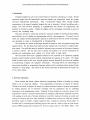
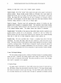
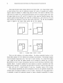
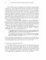
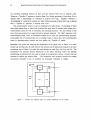
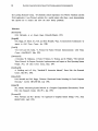
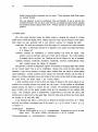
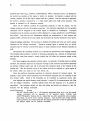
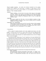
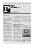
Figure 1. Typical DUSP displays. This image and the one on the next page illustrate two successive
images during an interactive session. The second image is created from the first by slight rearrangement of
some windows, and by adding new text to the Work Area window.
The Dusp extension of these facilities is intended not only to use a fast display output device,
but also" to take advantage of other opportunities offered by the display.
The spirit of Dusp is
illustrated in Figure 1: the display shows many "windows," each of which presents information
about a programming context.
One window contains a function definition being edited, one a
selected portion of the user's manual, one a message received from a colleague, one a typescript of
the user's activities, and several contain menus.
The user may alter the size and location of
RASTER GRAPHICS FOR INTERACTIVE PROGRAMMING ENVIRONMENTS
windows, and may bring partially-obscured windows "on top" for a clear view.
3
Commands to
Dusp are entered with a keyboard and a "mouse" coordinate input device.
The pIimary objective of the AOIS graphics package is to provide a high-performance service to
Interlisp programmers.
As a consequence, highest priority is placed on providing pleasant
interaction and avoiding errors of all sorts.
Although the, system offers some general-purpose
graphics facilities, its objectives are focused on the needs of Dusp, which are outlined below.
bits 4- 10) (JSYS 143 64 MODE) (* STPAR Silts
new mode word»»)
(SETPAGE)
124(setpage 72 100)
NIL
134-71
13+-load«MASINTER)QETMAILPOSl
FILE CREATED 23-JUN-77 15:29:0~
(GETMAILPOS)
(MASINTER>GETMAILPOS.j 1
1441S+-informail(t)
~Mail from MasintQr, 3:30PM]
,)
194-[Mail from Burton, 3:55PM]
Want to seQ it now? VQS
informail( t)
[Mail from Burton at bbn-tenexd, 3:55PM]
::J
SNDMSG
( INfOR.All
[LAMBDA (Fl)
(PRIN1 "[M~i1 from· FL)
(FILEPOS "Ft'olll: " MAILFIlE (BETMAILPOS)
~IIL NIL T)
SENDER .. (RSTRING MAILFILE DISPlAYROTBL)
(PR I N1 (SETQ SENDER (L -CASE SENDER T»
fl)
(PRIN1 ., • Fl)
(PRIN1 (OOATE lASTKNOWNMAll -34309144576
"2: 29AM")
f,lepOs[x;f11e;startjend
fL)
(if
•
(f11epos ·Subject:
~
RPRIN1 U]
" Fl))
fi1epos
w~s
written
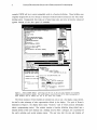
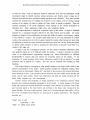
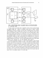
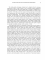
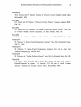
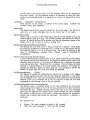
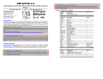
Figure 1 (continued).
Speed and capacity. The context sUlTounding a working programmer is enormous. Dusp aims to
display sizable chunks of this context as carefully-formatted text in windows (see Figure 1).
Remaining portions of the display are devoted to menus, cues pointing to more context, and the
like. When the user asks that a window be moved, or that an obscured window be placed on top of
those hiding it, a considerable portion of the display will need to be altered rapidly. For further
4
RASTER GRAPHICS FOR INTERACTIVE PROGRAMMING ENVIRONMENTS
reference, we shall refer to this as the "window update" operation.
Control of type in. Part of the "window" idiom requires that typein activity appear to take place in
arbitrary windows. Because Interlisp terminal facilities are full-duplex, this is quite siInple: the
program will wait for a key to be struck, and will then display an "echo character" in the proper
window. But typists often make mistakes, and will warit to backspace over characters, words or
entire lines. As this happens, we want the display to show the current input characters, without
extraneous editing characters so often seen on teletype paper.
Control of typeout.
Characters typed with operating-system assistance by Interlisp and other
programs must be directed to an appropriate window. This requirement arises because Interlisp
allows a user to initiate "inferior executives" that invoke arbitrary Tenex programs and yet to return
to the retained Interlisp context.
The display context must likewise be untouched.
Graphical detail. The flexibility of the raster-scan frame-buffer display should be exploited to use
graphical details to provide cues to the programmer. Examples are: italic text, boldface text,
different character font styles, special iconic symbols that have mnemonic value, attention-directing
forms such as white text on black background, different texture patterns, etc.
Graphical input. The user is provided with a "mouse," a coordinate input device with three
pushbuttons. The mouse rolls along a table top and is tracked by a cursor that moves on the
screen. The mouse can thus be used to point to objects already displayed on the screen, or simply
to identify a coordinate position. The three keys are remarkably versatile, provided the software for
handling them is sufficient: for example, combinations of keys can be struck as "chords"; a single
key action can be distinguished from two key depressions in rapid succession ("double clicking").
3. ADIS - The Graphics Package
The ADIS graphics package provides a collection of Interlisp functions for controlling graphical
output and input. Consistent with modern graphics system design, the facilities for output and
those for input are independent [Newman74]. This section provides an overview of the package;
more detail is presented in the appendix.
3.1 Graphical Output
The display image is represented in a frame buffer memory that records, for each pixel on a
606 x 808 display, whether the point should be white (0) or black (1). The output functions simply
alter values in the memory in order to alter the image. The frame buffer could be edited with only
two very simple functions, one to read the value of the pixel at a particular (x,y) location, and one
RASTER GRAPHICS FOR INTERACTIVE PROGRAMMING ENVIRONMENTS
to write the value.
5
Such an approach would be intolerably slow, and the programmer would
immediately begin to identify common editing operations, and thereby create a larger set of
functions that perform more specialized editing operations more efficiently. Thus ADIS provides
functions for drawing lines, for adding text characters to the display, and for moving existing
portions of the display, all coded to update the frame buffer as rapidly as possible.
These are
common operations in the DLiSP application, which depends on the careful presentation of
formatted text.
Other applications might stress other graphical objects.
Each output operation is directed at a particular region of the screen. A region is identified
primarily by a rectangular boundary defined by left, right, bottom and top edges.
All output
requests are clipped so that modifications are made only within the region; in this respect, a region
is very similar to a viewport. For example, region limits may be set to the boundaries of a DLiSP
window, thus ensuring that text will not appear outside the window either because too many lines
are displayed or because too many characters are placed on a given line. In fact, DLiSP uses regions
to operate within windows as well: to construct the label banner, to provide "scroll bars" at a
window's left edge, etc.
A region is not just a rectangular boundary, but also contains substantial information about
how graphical objects are to be displayed within the window. A region is thus like an abstract
object in an object-oriented programming language (e.g., Simula [Birtwistle73] or Small talk
In the
[Goldberg76]) - it contains data and routines for producing output on the display.
description of output functions given below, infonnation marked with an asterisk (*) is data
associated with an instance of a region.
This data can be examined and modified by ADIS
functions.
Each output function is designed to make specific changes to the frame buffer, which is the
ultimate representation of the image. Unlike graphics packages for calligraphic displays, these
functions build no intennediate "display file," and retain no data structure that contains information
about characters or lines. ADIS provides only two structures: the frame buffer, which describes the
image, and the region objects, which retain information that helps the output functions edit the
frame buffer contents (e.g., font descriptions).
Another concept used frequently in output operations is the combination junction, which
describes how previously-displayed information is to be treated.
A typical change to the frame
buffer will compute the function F(oldValue, newValue), where old Value is the binary value of the
pixel currently stored in the frame buffer, and newValue is the binary value computed by the
output function. The value of the function F (either 0 or 1) is stored into the frame buffer. Only a
few of the 16 possible binary functions arc used heavily in graphics applications.
provided are:
"Copy" new to old:
F 1(old,new) = new
"Paint" by adding black points:
The functions
6
RASTER GRAPHICS FOR INTERACTIVE PROGRAMMING ENVIRONMENTS
Fiold,new) = old OR new
"Erase" by complement of paint:
F 3(old,new) = old AND NOT new
"Invert" old image wherever new is present:
F 4(old,new)
old XOR new
FS(old,new)
F 6(old,new)
Fiold,new)
F 8(old,new)
=
=
=
=
old
NOT old
old AND new
new
A function to "draw aline," for example, will compute the coordinates of each point that lies on
the line. For each of these points, it will store into the frame buffer the value F(oldValue,l).
DitTerent choices of the combination function will produce different effects on the screen: Fl or F2
will cause the line to appear black; F 3 will cause it to appear white, and could be used to erase a
black line; by changing the value of each pixel along the line, F 4 will cause a line to appear,
regardless of what information has been previously recorded in the frame buffer.
The output functions are summarized in the following paragraphs:
Line. This function generates the portion of a line that falls within the region limits. The
endpoints of the line are specified by a "current position" recorded in the region, and a "final
position," provided as an argument. After the line is drawn, the current position is changed to
become the final position. Arguments: final position (x,y); width of the line; * current position
(x,y); * combination function; * region limits (left,right,bottom,top).
RasterOp. This function copies the image in a rectangular area of the screen to another place on
the screen, applying one of several modifications to the image as it is copied. The two rectangular
areas are called the "source rectangle" and the "destination rectangle." The function may reduce
the dimensions of the destination rectangle to fit within the region limits. The RasterOp function
computes a new value for each pixel in the destination rectangle using the expression destination: =
Fidestination,Fs(source,pattem», where the destination combination function F d ranges over Fl to
F4 and the source function Fs over Fs to F g. The "pattern" is a pixel value computed by repeating
a 4x4 pixel pattern over the entire screen. It is very useful for filling rectangles with constant
patterns, such as black, white, or a gray half-tone.
Arguments: destination rectangle
(left,right,bottom,top); source rectangle (left,right,bottom,top); 4x4 pattern (16 bits); combination
functions F d' Fs; * region limits (left,right,bottom,top).
RasterOp is a very versatile function. It allows the programmer to take advantage of imagery
already displayed, copying it to new places, altering its appearance, etc. Choosing F d =Fl and
Fs = Fs' the function will copy areas without alteration. A "scrolling" operation uses the copy
function to move a window's contents upward slightly; the versatility of the RasterOp function
RASTER GRAPHICS [<'OR INTERACTIVE PROGRAMMING ENVIRONMENTS
7
makes scrolling down, left, or right equally easy. The function can also be used to "invert" part of
the screen, changing images from "black on white" to "white on black" (Fd=F4' Fs=Fg, pattern all
1's, source and destination rectangles identical). Inversion of this sort is useful for providing
feedback to the user (Figure 1 shows the word RSTRING highlighted in this way). The reader is
invited to ponder other combinations as well.
found in [Newman79].
Text.
More information on the usc of RasterOp can be
The text output function is by far the most complicated, as it must efficiently achieve a
variety of effects to support windows. Each character of the output string is looked up in a jont,
which records a small rectangular bit pattern for each character. This pattern is used to modify the
display in much the same way RasterOp does; the combination function governs the display of the
character. Clipping to the region limits may discard entire characters or portions of characters.
After each character is displayed, the "current position" is changed, due either to the width of the
character just displayed or to its formatting effect (e.g., carriage returns, tabs, line feed). A scrolling
feature can be enabled to "open up" space between lines or space within a line when text is to be
inserted. The scrolling is achieved with RasterOp, as described above. Arguments for text output
are: text string; * current position (x,y); * region limits (left,right,bottom,top); * combination
function; * style: font, bold, italic; * formatting: left margin for carriage return, line spacing for line
feed, tab spacing, scroll flag for vertical or horizontal scrolling, pattern to clear scrolled area.
Pixels. This' call specifics values of pixels to st'Jre in a rectangular area of the screen. This function
is not used heavily; it is used occasionally to produce complex patterns that the other functions
cannot. Arguments: destination rectangle (left,right,bottom,top); array of pixel values; * region
limits (left,right, bottom,top).
Caret. The "current position" in a region may be illuminated with a blinking caret. The facility is
normally used to indicate where typed characters will next be displayed. The caret is disabled by
setting the blinking rate to zero. Arguments: 16x16 pattern to use for the caret; blinking rate;
current position (x,y) which will vary; * region limits (left,right,bottom,top).
*
Region data. ADIS includes functions for reading and writing all state variables associated with
regions. These variables are flagged with asterisks (*) in the descriptions above. The region objects
of ADIS are thus state-transparent: all state can be read and written.
Dusp uses this capability
frequently. Suppose that a function is using a region to place text and graphics on the display, but
that its computation is internlpted by a "break point." Such a break might occur because the user
types a special interrupt character, or because an error is detected. The BREAK package is invoked,
which interacts with the user to repair the damage. This package uses the display, however, and
might disturb the display-generation of the interrupted function.
BREAK saves and restores the state of any regions it uses.
To prevent this disturbance,
8
RASTER GRAPI lICS FOR INTERACTIVE PROGRAMMING ENVIRONMENTS
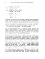
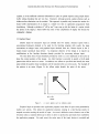
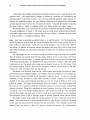
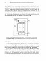
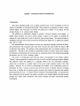
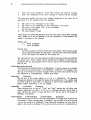
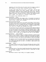
Each output function makes changes directly in the frame buffer. The "image editing" nature
of these functions forces onto the application program the burden of managing screen updates.
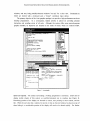
Figure 2 shows an example of a window being moved in Dusp. The motion is achieved in four
steps: first Rl is copied to Rl' with the RasterOp function; then R2 is similarly copied to R2'; then
the region limits are set to R3, and R3 is cleared to white using the RasterOp function; then
whatever graphical material thought to lie within R3 is re-displayed (Le., calls to the Line, Text, and
Pixel functions are performed to alter the frame buffer within R3).
The fact that all graphical
output is clipped to the region limits greatly aids the last operation.
I
I
-
I
R1
R1'
I --..,--
-R2
R3
Figure 2.
IR2'
I
I
A partially hidden window is moved.
There are other solutions to the update problem.
By adding considerable hardware to the
frame buffer, dynamic "2 1/2 D" effects can be provided by the hardware. This technique requires
several translatable image planes and a "color map" to resolve priorities. On a simple frame buffer
with a single bit per pixel, the update sequence can be managed by software (e.g., see PI CO
[Sprou1175]), but to do so requires maintaining a large data structure describing all potentially-visible
graphical objects.
In general, updating the screen requires an expensive computation much like
hidden-surface elimination. The sequence described above for IDoving a window is much faster, but
it works well only for a limited number of cases (e.g., rectangular regions of the screen).
Thus, although responsibility for screen management is borne by the application program, the
technique offers advantageous flexibility as well as a burden. Experience with ADIS suggests that it
is reasonable to require the application program to assume substantial responsibility for screen
RASTER GRAPHICS FOR INTERACTIVE PROGRAMMING ENVIRONMENTS
9
updates, as it has sufficient contextual information to plan an update sequence using simple framebuffer editing functions that are very fast.
Expensive, although general, update schemes such as
hidden-surface elimination can be avoided. This approach is possible only because the notion of a
frame buffer representation of an image is a simple one that no application programmer finds
bewildering. Although a plethora of "off by one" bugs crop up (do the limits of a region include
the points at the edge?), a frame buffer has none of the complexities of display file formats for
calligraphic displays.
3.2 Graphical Input
DLISP'S
needs for interactive input are divided into two classes: character typein from a
conventional keyboard, destined to be used by the Interlisp program with exactly the same
conventions as teletype input; and graphical input obtained from the 5-button keyset or the 3button mouse coordinate input device. An important objective of the design is to require no
modifications to the Interlisp functions already provided for processing teletype input.
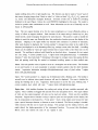
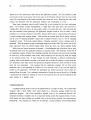
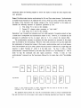
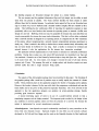
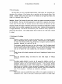
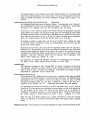
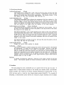
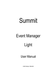
'Inc only direct form of input feedback provided by ADIS is a cursor displayed on the screen to
show the current position of the mouse. An ADIS function is provided to specify a 16x 16 pixel
pattern that will be used as a cursor. In addition, two offsets are specified that identify the exact
point within the pattern whose coordinates will be reported when an event occurs. For example, if
the pattern is an arrow (Figure 3), the offsets might identify the point of the arrow.
••••
• all
•••••
••
••
••
yoffset
<
>
x offset
Figure 3.
A cursor pattern and its reference point.
Graphical input is reported to the application program in the form of input events generated by
explicit user actions.
This allows the application program, running in a time-sharing system, to
suspend execution awaiting the arrival of input. An event is defined to occur whenever one of the
8 buttons makes a transition (from up to down or down to up) that has previously been enabled by
the application program.
For each event, the entire state of the input devices is recorded and
10
RASTER GRAPHICS FOR INTERACTIVE PROGRAMMING ENVIRONMENTS
placed in an event queue that is later read by the application program. The state includes: (1) the
(x,y) location of the mouse cursor; (2) current states of all 8 buttons; (3) time since the most recent
event; (4) a specification of the button transition that caused the event. Reporting the entire state
reduces the likelihood that the application program will misinterpret an event.
Some input techniques require careful timing that is not provided by the event mechanism
alone. For example, consider distinguishing a "single click" (key goes down, then up) from a
"double click" (key goes down, up, down again within 1/3 second, then up). After observing the
first two transition events (down,up), the application program needs to wait for either a down
transition or 1/3 second, whichever comes first. Because Dusp nms in a time-sharing environment,
it cannot perform such accurate timing. ADIS provides an internal timer that is started whenever
one of a set of "starting transitions" occurs and is stopped whenever one in a set of "stopping
transitions" occurs. If the timer expires before a "stopping transition" occurs, a timeout event is
generated. Thus the program trying to distinguish single and double clicks will receive one of two
input sequences: down, up, timeout (single click); down, up, down, up, timeout (double click).
Both events and typein characters are queued. A knowledgeable user is therefore free to work
occasionally faster than the application program can process inputs. This technique works only if
the application program refrains from changing frequently the parameters that govern the reporting
of events (e.g., which transitions cause events, which transitions start and stop the timer, the length
of the timeout period, etc.). If such changes are made frequently, a difficult synchronization
problem arises: events already recorded in the queue may no longer be classed as events using the
new parameters; other input actions not queued and forgotten should have been recorded as events
given the new parameters. ADIS assumes that the application program will set these event
parameters once at the beginning of a session so as to generate events of any sort that might be
needed by the application. Thereafter, the application can discard unwanted events as they are
extracted from the queue. It is a necessary consequence of letting the user get ahead (Le., of having
a queue) that the criteria for causing an event be more general than the criteria imposed by the
exact context of a specific event.
4. Implementing ADIS
A graphics package such as AOIS can be implemented in a number of ways. On a stand-alone
computer with a frame buffer, ADIS could simply be a subroutine package linked into the
application program. The Dusp application requires ADIS to be partitioned between two
computers: Interlisp is available only on a large time-sharing system that supports dozens of users,
while display and input facilities are available only on several dozen personal Alto minicomputers
[fhacker79]. The machines are linked by the Ethernet a packet-switched network [Metcalfe76].
RASTER GRAPHICS FOR INTERACTIVE PROGRAMMING ENVIRONMENTS
11
4.1 Multiple Processes
Before exploring the way in which AOIS uses the communications network, let us examine the
implications of executing portions of the Dusp/ ADIS system as separate processes. The system
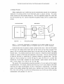
divides naturally into three processes (Figure 4): The DLISP application program D.a, which calls
the ADIS functions D.g; 0.0, a process responsible for graphical output; and OJ, a graphical input
process.
Timesharing system
Minicomputer
G.o
D.a
D.g
G.i
Application
ADIS graphics package
Figure 4. A three-process implementation: D.a (application) and D.g (graphics package) run on the
timesharing system; G.o (graphical output) and G.i (graphical input) run on a personal minicomputer.
Communication from one process to another is achieved with streams. These are FIFO queues
of 8-bit bytes: the sending process inserts bytes into the stream and may block execution if the
queue is full; the receiving process extracts bytes in the same order and may block if the queue
becomes empty. The processes control each other by means of a "high-level protocol" [Sprou1178]
encoded as a sequence of 8-bit bytes and transported via the streams. ADIS uses a protocol format
in which the first byte is a coded form of a command, followed by argument bytes. Thus D.g
might use 4 bytes to instruct G.o to set the left edge of a region: the first byte is a number that
identifies the "set left edge" command, the second identifies a region instance, and the last two
form a 16-bit integer to be used as the new left edge.
The majority of the communication among these processes is of a very simple sort that requires
no synchronization. For example, communication from D.g to 0.0 to cause changes to the frame
buffer does not require synchronization - the flow of information is unidirectional. The Interlisp
portion of the graphics package (D.g) actually saves a duplicate copy of most of the region data
(font, italic, bold, scroll flag, etc.) so that the Interlisp program may read this data without requiring
communication with processes 0.0 and OJ.
12
RASTER GRAPHICS FOR INTERACTIVE PROGRAMMING ENVIRONMENTS
A need to synchronize may arise if information input to D.g depends on information recently
output from D.g. This need arises because the interprocess communication paths have substantial
buffering: if D.g completes output to G.o and then reads some input from Gj, was the input
actually generated by Gj before or after the output was processed by G.o? For example, suppose
D.g outputs a command to alter the timeout interval. This command is transmitted to G .0, then to
OJ, and the new timeout value is recorded in a table inside Gj. But the path from Gj to D.g may
contain several buffered event descriptions; as D.g reads them, it may wish to know which events
were recorded before the change, and which afterward. Clearly, this need can be met by
propagating a special mark command around the loop: D.g to 0.0 to Gj to D.g. As D.g reads
input, it will first find events recorded before the change, then it will find the mark, and finally it
will find events recorded after the change.
Although such a synchronization primitive is technically easy to provide, synchronization is
almost never necessary. We observed above that no information is returned to D.g from 0.0, so no
synchronization of output is necessary. The input process, OJ, does return information to D.g that
depends on parameters sent from D.g. However, as we remarked in discussing input facilities, these
parameters are best set only during initialization, thus avoiding synchronization.
Although an implementation of a graphics system using several cooperating processes is not
complex, care must be taken to avoid needless synchronization difficulties.
Consider two
implementations of the cursor function described above:
1. D.g transmits the 16x16 cursor pattern to Gj (via 0.0), but saves values of the x and
y offsets locally. Whenever it extracts an input event from the queue being filled by OJ,
it adds these offsets to the (x,y) cursor position reported by OJ.
2. D.g transmits the pattern and offsets to OJ (via G.o). Whenever Gj detects an input
event, it adds the offsets to the mouse coordinates as it constnlcts an event description,
just prior to entering it in the queue.
Only the second method works properly, because it intrinsically synchronizes the offsets and the
cursor patterns. Method 1 will not work because it may use offsets for a cursor shape that was not
actually being displayed when the user struck the key that caused the event.
4.2 Programming environments and operating systems
If the diagram of Figure 4 were an accurate picture of the processes involved in the
DLISP/ ADIS . system,
the three-process design could be easily and cleanly implemented.
Unfortunately, various deficiencies of the Interlisp environment and of the Tenex operating system
make such a simple implementation impossible. The problems stem from the ways in which
"terminal I/O" is handled by the two villains. This section explains the difficulties in the hope that
future operating system and language system designs will avoid the problems.
RASTER GRAPHICS FOR INTERACTIVE PROGRAMMING ENVIRONMENTS
uninvited
text _ _ _
13
S.to
311
S.tl
TJ
G.tl
Figure 5. Actual implementation of ADIS. D is the application program, T are operating-system processes,
and G are processes in the graphics terminal. Communication is achieved with four streams (S) transported
by a packet-switched network.
The basic problem is that systems make it impossible to funnel all input and output through
the graphics package D.g.
Instead, two additional streams shown in Figure 5 provide
communication to and from a "terminal," in the sense that a timesharing system views a terminal.
The two processes G.ti and G.to interact with Gj and G.o in very simple ways: when a key is
struck on the keyboard, Gj passes it to G.ti, which sends it over the terminal stream to Tenex.
When Tenex generates output characters, the "terminal text" is sent to G.to, which passes it on to
G.o, simulating the effect of a Text call. The text characters are displayed on the screen by G.o,
using parameters supplied by a region: current position, font, scrolling options, etc. In this way,
text generated in a conventional way by Interlisp modules or by Tenex can be presented in a
carefully-controlled way on the screen. The ARPA network graphics protocol does not allow precise
treatment of such "unescorted text"; the DLISP application clearly requires it.
The Interlisp programming environment, on which the DLISP application is based, depends
critically on the properties of the "terminal IIO" streams. These streams are subjected to special
processing within the Tenex operating system. For example, normally invisible control characters
can optionally be converted to two character sequences (e.g., control C is printed as "tC"). More
importantly, Tenex implements an echo path on which Interlisp depends: normally, as each
character of terminal input is read by Interlisp , Tenex echos the character by sending it as output to
the terminal. Because it is impractical and inefficient to replicate these functions within DLISP, the
ADIS design had to continue to use the normal terminal 110 streams for all character input and
output, and use the graphical streams for all other traffic.
14
RASTER GRAPHICS FOR INTERACTIVE PROGRAMMING ENVIRONMENTS
Unfortunately, the exisiting terminal input and output streams cannot be used reliably to carry
graphical traffic.
The output stream is subject to invasion by "uninvited text" generated by the
operating system or the Tenex executive. Such text may garble the graphical output protocol. In
addition, the application program may type arbitrary characters to the terminal and inadvertently
generate sequences that interfere with the graphical protocol. Graphical information encoded on
the input stream is subject to echoing, which may further garble the output stream.
The problem faced in the ADIS design is to provide a conceptual view similar to Figure 4 with
the actual configuration of Figure 5. The design requires solving several synchronization problems:
rather than a single output stream in Figure 4, there are two in Figure 5. Similarly for input. Each
of these problems is considered separately below.
Input. Input may be generated as graphical events or as typed characters. The Dusp application
cannot anticipate the kind of input that will be generated, and must therefore wait for activity on
either of the two input streams. Tenex does not provide facilities to wait for input from either of
two sources. In addition, the Interlisp functions that gather typed input (READ and the like) do not
offer much opportunity for intervention: once READ is called, tests for graphical input cannot be
performed.
The ADIS design uses the S.ti stream to notify the Interlisp program that input has occurred.
Thus the program can request input from this stream, blocking if none is yet present, and receive
information about the next input. Characters typed at the keyboard are sent over this stream, just
as for normal terminal input. If a graphical event occurs, two actions are taken: a full event record
is delivered over the S.gi stream, and a single control character is sent over the S.ti stream. Thus
the Interlisp program waits for input on the S.ti stream, reads the control character, and then
extracts the event descriptor from the S.gi stream.
This design is not arbitrarily chosen, but is a rather delicate path through the turmoil of Tenex
and Interlisp character-handling facilities. For example, the event description is not transmitted on
the S.ti stream because the bytes in the description might be echoed. It turns out that the
processing of input characters in Tenex allows echoing of control c!laracters to be selectively
disabled, so the single control character transmitted over the S.ti stream to herald an event is not
subject to echoing. The design is also delicately fitted into Interlisp. The Dusp program calls
READ (or one of its variants) to gather input from the tenninal; this function begins reading bytes
from the S.ti stream. When READ encounters the control character, it invokes a READ rnacro, which
can contain a call to an arbitrary Interlisp function. This function can read the event description
from the S.gi stream, and then return to READ, where more typed characters can be assembled.
This mechanism allows a user to interrupt typein to generate graphical events with the mouse.
This rather intricate design allows the Interlisp program to receive input from several input
devices. The control character is used to synchronize the two input streams: it marks the S.ti stream
at, each place that input should be extracted from the S.gi stream. Thus, although character and
graphical input arc forced to flow over separate asynchronous streams, the synchronization
15
RASTER GRAPHICS FOR INTERACTIVE PROGRAMMING ENVIRONMENTS
mechanism allows the Interlisp program to receive the inputs in exactly the same sequence they
were generated.
Output. Providing output requires synchronizing the S.to and S.go output streams. Synchronization
is needed because characters to be displayed flow on S.to, while S.go carries information that affects
the display of the characters: font changes, changes to the "current position" in the region, etc.
Consider the following sequence of operations performed by D.a:
1. Text string Tl is sent to the terminal.
2. Protocol PI changes region parameter to "style italic."
3. Text string T2 is sent to the terminal.
Operations 1 and 3 transmit text characters over S.to, while operation 2 transmits protocol on S.go,
a stream that is independent and asynchronous relative to S.to. However, it is essential that the
operations be performed by G.o in proper order (1, 2, 3) to achieve the desired effect
The synchronization necessary to guarantee that these operations are processed in the proper
order is provided by the ADIS package. Whenever ADIS sends commands over S.go that might alter
the interpretation of terminal text output, it first sends a synchronization mark over both streams.
Over S.to (and thence to G.o) it sends a special character (control C) followed by a single digit; this
Via S.go it sends a "begin
sequence is called "SyncSto d," where d is the digit used.
synchronization" command followed by the same digit, referred to as "SyncBeginSgo d." Then it
Finally, it sends an "end
sends via S.go the commands that alter region parameters.
synchronization" command over the S.go stream followed by the single digit, called "SyncEndSgo
d."
S.to stream
GJGJGJ
~ ~ ~
S.90 stream
D
Sync
Begin
S90
4
D
ync
Sto
4
888
~ ~ ~
888
~ ~ ~
Sync
End
Sgo
4
D
Figure 6. Sync markers tell when to "switch" interpretation from one stream to the other to assure
processing of text and protocol in the proper order.
The graphical output process G.o uses the synchronization marks to process commands from
D.g and text from G.to in the proper order using the following algorithm (see Figure 6). Initially,
16
RASTER GRAPHICS FOR INTERACTIVE PROGRAMMING ENVIRONMENTS
G.o processes commands received on S.go and text received from G.to in arbitrary order.
Whenever a "SyncSto d" sequence is received from G.to, further processing of bytes from G.to is
delayed until a "SyncEndSgo d" command is received over S.go.
Similarly, whenever a
"SyncBeginSgo d" command is received over S.go, further processing of bytes from S.go is delayed
until a "SyncSto d" sequence is received from G.to.
This synchronization scheme is easy to implement and quite robust. If processing of bytes
from either stream (S.go or from G.to) is delayed for more than 10 seconds while waiting for a
synchronization mark, the wait is terminated, and processing proceeds. The only damage in this
cas~ is that some terminal text output will not be properly displayed. The "digit" argument to the
synchronization marks, which is incremented modulo 10 for each new synchronization operation,
avoids global loss of synchronization due to program bugs or restarts that omit synchronization
marks or operating-system inserted text that garbles the "SyncSto d" marks.
Discussion. This section has described the modification of the simple view of Figure 4 in which
streams S.go and S.gi carryall traffic between the terminal and the application program to the more
complicated view of Figure 5 in which four main streams are used: S.go, S.gi, S.to, and S.ti. This
arrangement was necessary because deficiencies in the Tenex operating system and Interlisp
programming environment were too costly to remedy by invading these systems. Instead, ADIS was
contorted to achieve the desired effect.
The contortions were necessary because the existing
environment contained a view of terminals too thoroughly embedded to change.
uninvited
text
.....
.......
;'
- --)
~
T.o
,.....
/~
I
I
I
I
I
I
I
I
I
I
I
I
echo
path
D.a
if'
----
Figure 7.
T.i
./
........
D.g
~
.;'
......
Terminal and graphical traffic are carefully multiplexed on two streams.
RASTER GRAPHICS FOR INTERACTIVE PROGRAMMING ENVIRONMENTS
17
The operating system and language environment can be designed to allow the two-stream
implementation of Figure 4. What is required is a view of "terminals" that allows multiplexing of
normal character input/output and protocol messages that are not subject to modification by the
operating system (Figure 7). The program needs several output facilities: (1) the ability to output
text characters; (2) the ability to output byte sequences of arbitrary length that will not be altered
by the operating system; and (3) some mechanism for dealing with other traffic that is sent to the
terminal by the operating system.
These "uninvited text" messages, such as "System going down in
30 minutes," are lethal invasions of any formatted communication between a computer and a
terminal. This is a severe problem with terminals such as storage-tubes: the system message may be
interpreted as graphical commands! Facilities needed for input are: (1) a mechanism to allow
protocol messages to bypass the echoing machinery; and (2) a design for character echoing that
echoes characters as they are read by the application program. This last facility is available in Tenex;
without it, echoed characters cannot be placed carefully on the screen. Users of systems that echo
characters as they are typed (e.g., DECSystem-10) are familiar with the result: typein and typeout
are thoroughly intenningled, preventing careful presentation of either.
Terminal input/output facilities in the programming environment also need careful attention to
support formatted communication ("protocol") with a terminal.
Although the ideal solution is to
funnel all terminal input and output through the graphics package, almost no programming
language systems permit it.
Instead, existing facilities for terminal input and output must remain
intact, and additional independent mechanisms can be provided by the graphics package. Problems
with output are modest, provided the terminal interprets normal text characters generated by the
system in the proper way. Calls on the graphics package can generate "terminal output protocol"
sequences to display graphical objects or to alter the interpretation of text characters. (This is the
approach taken by the Tektronix terminals, and is quite successful.) Input presents a more intricate
problem: descriptions of graphical input arriving in the midst of character typein will interfere with
the character input expected by the programming system. TIle use of READ macros to solve this
problem in the ADIS package is an idiosyncratic solution applicable only in Interlisp. Programming
environments that allow careful control of terminal lID (e.g, SAIL) present fewer difficulties.
Manufacturers of graphics terminals have chosen to solve this problem by transmitting graphical
input only when demanded by the application program: this guarantees that the program is in a
suitable state for accepting graphical input.
Unfortunately, many have taken an additional step as
well: the graphical input device is active only when the program is demanding graphical input (e.g.,
Tektronix terminals), and the application program must activate only one input device at a time.
Perhaps the cleanest way to solve all of these problems is to solicit assistance from the
operating system to insert processes between application programs and the terminal (Figure 8).
These processes provide to the application program a simple view of the terminal as streams of
characters (if that is the view expected by the programming environment), but can communicate
with the terminal using carefully formatted protocols.
These processes may connect with other
processes that desire communication with the user (e.g., uninvited text). These processes become, in
18
RASTER GRAPHICS FOR INTERACTIVE PROGRAMMING ENVIRONMENTS
effect, a definition of how the user's single tenninal is to be used to communicate with many
application processes. Most operating systems contain such processes (they are shown in Figure 5 as
T.o and T.i), but prevent their alteration or substitution by the user. The ability to connect the
tenninal streams of an application program to user-defined processes would greatly ease the
introduction of new tenninal types, would simplify the implementation of tenninal communications
in computer networks, and would also allow one user-defined process to invoke another in a simple
way. Some operating systems implement "pseudo-teletypes" that attempt to serve this function, but
most implementations are either too inefficient or too awkward to use.
uninvited
text
......
/
- --)
S.to
......
D.to
",.
/~
l'
I
I
I
I
I
I
I
I
I
I
I
echo
path
D.a
D.g
I
l'
----
l'
./' S.tl
D.ti
'"
Figure 8. User-defined processes control the graphics terminal. Any processes wishing to use the terminal
(e.g., the application program and the operating system, the source of uninvited text) communicate with the
terminal-controller processes.
4.3 Network Issues
A packet-switched network is used to implement four of the interprocess communication
streams used by ADIS (S.go, S.gi, S.to, S.ti). The network introduces no special problems--it is the
introduction of several processes and the confrontation with programming language and operating
system limitations described in the previous section that complicate the implementation.
All four streams are implemented with a "byte stream protocol" [Boggs80] similar to TCP
[Cerf74]. The two streams that carry terminal traffic (S.to and S.ti) use a "Telnet protocol"
implemented with streams. (Telnet is the name of the terminal protocol in the ARPAnet
[Davidson77].) The Tenex operating system interfaces the character input! output facilities available
to the Interlisp program to the network protocol. This interface ensures that characters output from
RASTER GRAPHICS FOR INTERACTIVE PROGRAMMING ENVIRONMENTS
19
the Interlisp program are forwarded through the stream in a timely fashion.
The two streams used for graphical information (S.go and S.gi) simply use the ability to send
bytes from one process to another. The Tenex network interface for these streams is rather
different than that for terminal streams. In particular, bytes output by D.g are not forwarded over
S.go in a timely way, but are buffered until a sizeable number (roughly 500) are available to fill a
packet. This buffering has the unfortunate effect of requiring the application program to issue
periodically calls to an ADIS function that instructs the operating system to transmit a buffer even
though it is not full. Buffering of this sort may be acceptable for streams that access disk files, but
is quite unacceptable for streams that carry timely information. This fact is all too often overlooked
when a network interface is designed for an operating system: it is slipped into the "file" machinery
of the system, without recognizing that a network connects computational processes operating in a
timely way. What is needed is the ability to declare that a stream contains timely information, and
that no bytes should be buffered for very long. Such a facility is necessary for terminal and
network streams; it also has applications for file streams (e.g., transaction recording).
The particular network implementation in ADIS seems to introduce no noticeable performance
problems. During heavy output use, only about 400 bytes/second are transmitted over S.go and
S.to combined. Extensive use of the RasterOp function helps to keep this figure low. Input traffic
is of course lower still. An event report, even though it records the state of all input devices,
requires only 9 bytes. This message fits easily in a single packet, and therefore requires no more
network traffic that does a single character being typed.
5. Conclusion
Two aspects of the ADIS graphics package have been described in this paper. The functions of
the graphics package offer a small set of primitive ways to modify rapidly the contents of a frame
buffer. These primitives place on the application program the burden of managing screen updates.
However, this burden is lesseneJ by the ease with which the programmer understands and uses the
frame buffer and by the power of the primitives (especially RasterOp). One of the rewards of this
approach is that the application program can optimize its screen-updating strategy, thereby
providing good interactive response.
A second interesting aspect of ADIS is its use of a packet-switched network to link a
timesharing computer and the display terminal. The important point revealed by the design is that
any trickiness in network graphics comes not from the presence of a network, but because the
system is implemented by several asynchronous processes.
Acknowledgements. ADIS depends on superb workmanship contributed by many researchers at the
Xerox Palo Alto Research Center. Especially helpful for this effort was the network software
developed by Ed Taft and Dave Boggs, and the work on the RasterOp function by Dan Ingalls and
20
RASTER GRAPHICS FOR INTERACTIVE PROGRAMMING ENVIRONMENTS
the Learning Research Group. Of absolutely critical importance were Warren Teitelman and his
Dusp application: it was Warren's ambition for a usable system rather than a mere demonstration
that spurred me to analyze and solve the more thorny problems.
References
[Birtwistle73]
G.M. Birtwistle, et aI, Simula Begin, Petrocelli-Charter, 1973.
[Boggs80]
D.R. Boggs, J.F. Shoch, E.A. Taft, and R.M. Metcalfe, "Pup: An Internetwork Architecture," to
appear in IEEE Trans. Comm., Jan. 1980.
[Cerf74]
V.G. Cerf and R.E. Kahn, "A Protocol for Packet Network Interconnection," IEEE Trans.
Comm, cOM-220:637, May 1974.
[Davidson77]
1. Davidson, W. Hathaway, J. Postel, N Mimno, R. Thomas, and D. Walden, "The ARPAnet
Telnet Protocol: Its Purpose, Principles, Implementation and Impact on Host Operating System
Design, Proc. 5th Data Comm. Symp., Sept. 1977.
[Goldberg76]
A. Goldberg and A.C. Kay, "Smalltalk-72 Instruction "'Manual:' Xerox Palo Alto Research
Center, SSL-76-6, 1976.
[Metcalfe76]
R.M. Metcalfe and D.R. Boggs, "Ethernet: Distributed Packet Switching for Local Computer
Networks," CACM, 19(7):395-404, July 1976.
[Mode179]
M.L. Model, "Monitoring System Behavior in a Complex Computational Environment," Xerox
Palo Alto Research Center, CSL-79-1, Jan. 1979.
[Newman74]
W.M. Newman and R.F. Sproull, "An Approach to Graphics System Design," Proc. IEEE,
62(4):471-483, April 1974.
RASTER GRAPHICS FOR INTERACfIVE PROGRAMMING ENVIRONMENTS
21
[Newman79]
W.M. Newman and R.F. SprOull, Principles of Interactive Computer Graphics, second edition,
McGraw-Hill, 1979.
[Sproull74]
R.F. Sproull and E.L. Thomas, "A Network Graphics Protocol," Computer Graphics, 8(3):27,
Fall 1974.
[Sprou1175]
R.F. Sproull and W.M. Newman, "The Design of Gray-Scale Graphics Software," Proc. Con/.
on Computer Graphics, Pattern Recognitiof4 and Data Structure, May 1975.
[Sprou1178]
R.F. Sproull and D. Cohen, "High-Level Protocols," Proc. IEEE, 66(11):1371-1386, Nov. 1978.
[feitelman77a]
W. Teitelman, "A Display-Oriented Programmer's Assistant," Xerox Palo Alto Research Center,
CSL-77-3, 1977.
[feitelman77b]
W. Teitelman, "A Display-Oriented Programmer's Assistant," Proc. 5th Int. Joint. Con/.
Artificial Intelligence, pp. 905-915, 1977.
[feitelman78]
W. Teitelman, ed., "Interlisp Reference Manual," Xerox Palo Alto Research Center, Oct. 1978.
[Thacker79]
C.P. Thacker, E.M. McCreight, B.W. Lampson, R.F. Sproull, and D.R. Boggs, "Alto: A
Personal Computer," to appear in D. Siewiorek, C.G. Bell, and A. Newell, Computer
Structures: Readings and Examples. second edition, McGraw-Hill, 1979.
Appendix - INTERLISP DISPLAY PRIMITIVES
1. Introduction
This report describes briefly a set of display primitives that we have developed at PARC to
extend the capabilities of Interlisp [feitelman78]. These primitives are designed to operate a rasterscanned display, and concentrate on facilities for placing text carefully on the display and for
moving chunks of an already-created display.
The primitives are deliberately designed to provide a low-level interface to the display. A
display output primitive will cause a specific change to appear on the display by changing the
contents of a frame buffer that is used to refresh the raster-scanned image. The primitives make no
assumptions about the sorts of data structures for describing the display that an application program
may wish to build.
Our implementation of these primitives involves two computers: Interlisp is executed on MAXC,
and communicates with a program called Chat which maintains the frame buffer that drives a 808
by 606 point raster display. The existence of the communications link is not entirely invisible to the
programmer. Although it ably provides the bandwidth necessary to achieve rapid screen changes,
the mechanics of transmitting and receiving data are complicated both by the Interlisp programming
environment and' the Tenex operating system.
One source of complication comes from the need to accommodate on the display ordinary
"teletype" output generated by Interlisp and Tenex, as well as carefully-consllucted graphic displays.
The primitives resolve this problem in a reasonably effective way: the unformatted "teletype"
output may be directed to a specific region of the screen under complete control of the LISP
program. However, we are forced to acknowledge the existence of two independent sources of
information for Chat: a teletype connection that carries the stream of teletype characters emerging
from Tenex or Interlisp and a separate graphics connection that carries the cha,racters and graphics
protocol generated by LISP. As with the Network Graphics Protocol [Sprou1l74], it is important that
these connections be kept separate: the graphics connection must transmit highly structured protocol
messages that cannot suffer interference from system messages and other uncontrolled teletype
transmissions.
INTERLISP DISPLAY PRIMITIVES
23
2. The ADIS functions
This report does not cover the detailed implementation of the system, but concentrates on a
description of the collection of LISP functions that are provided, and their intended effects. Each
function is named ADISXXX; the actual names of the functions use all upper-case letters, even
though the description below does not.
ResetSave. Several of the functions for setting state variables use argument conventions that permit
use with ResetSave. They have the following properties: (1) called with no arguments, they return a
"current state;" (2) when called with legitimate arguments, they interpret the arguments and then
~eturn the "current state" before the alteration induced by the arguments; (3) called with a "current
state" (either a list or a number) as argument, they reset their state. Functions with these properties
are flagged (ResetSave). Note that the value returned by such a function is usually a pointer to an
internal ADIS data structure. If the calling program wishes to make any use of the value, it should
be copied
2.1 Initializing the Chat display
ADIsInit[n]
Initializes a graphics connection to Chat for all graphics output. If a connection already
exists, it is first closed cleanly, and then re-opened. If the connection can be established,
the result of this function will be a LISP file that allows a program to perform I/O to the
connection; otherwise, the result will be NIL.
The parameter n specifies how many text lines at the bottom of the Chat display should
be reserved for the initial "teletype simulation area," in which characters typed by MAXC
over the teletype connection will be displayed. Note that the size and location of this
area can be altered with ADIS functions after the connection is initialized.
ADIsCheck[]
Checks the state of the display connection, and closes it if something is found to be out
of order.
ADIsClose[]
Closes the connection cleanly, and returns the entire Chat display to "teletype
simulation. "
ADISOFILE
The global variable ADISOFILE is set to the file returned by AOIsInit, or NIL if no
connection is opened. If other ADISxxx routines find AOISOFILE null, they return without
transmitting protocol over the (non-existent) connection. If the program becomes
detached, if the Chat program crashes, or if the message 10 OATA ERROR appears on your
LISP job and you are forced to re-enter, the setting of ADISOFILE is likely to be invalid.
Before calling any other ADIS routines, ADISCheck should be called to test carefully the
state of the connection. AOISCheck sets ADISOFILE accordingly.
ADISFlush[wait]
This function causes any partially-filled output buffers on the graphics connection to be
transmitted to Chat Most of the ADISxXX functions given below do not flush output
24
RASTER GRAPHICS FOR INTERACfIVE PROGRAMMING ENVIRONMENTS
buffers because further commands may be issued. Those functions which flush output
are marked (Flush).
The wait argument is used to synchronize Chat and Interlisp: if wait is nOn-NIL, the
ADISFlush function will not return until Chat has successfully processed all the protocol
and characters already shipped from MAXC. Waiting requires all end-to-end exchange of
protocol.
2.2 Display output
The ADIS output functions change the ciisplay image by changing the contents of a frame
buffer used to refresh the display screen. Display output for Chat is always directed at some region.
Each region has state associated with it, and ADISxxx functions for changing the state:
ADISLimits: The limits are coordinates of the four edges of a rectangular box which surrounds
the region. If information directed to be displayed in the region lies outside these limits,
it is clipped off.
ADIsSetX, ADIsSetY (or ADIsSetXy): A "current position" (cp) within the region. This
position is used to determine where text or lines will be displayed. The current position
is changed both by the three "set" functions and by the display of a line or character.
ADISBold, ADISItalic, ADIsSetCR, ADIsSetLF, ADIsSetTab, ADIsFont, ADIsPrintMode: These
state variables govern the display of characters.
Chat provides a number of independent regions. All functions for changing region state operate
on one "current region" (CR) as set by ADIsRegion. Because Chat stores the basic region state
internally, it may not be necessary to change region variables often but simply to switch regions
using ADIsRegion. ADISInit initializes all the regions with reasonable defaults, sets the limits of
region 0 to a teletype simulation area at the bottom of the screen, sets the limits of other regions to
the entire screen, and makes region 1 the "current region."
A fixed coordinate system is used to direct the display of objects on the screen; regions do not
establish new coordinate systems even though they clip output. (In the parlance of conventional
graphics systems, the region is a viewport, but not a window. No coordinate transformation takes
place.) ADISInit will set four global variables which give the dimensions of the available Chat
screen. The coordinate system is (SCREENXMIN, SCREENYMIN) at the lower left corner, and
(SCREENXMAX, SCREENYMAX) at the upper right Since the Chat screen is fixed in size, these values
are actually (0, O) and (605, 807).
In the functions that follow, a RECfANGLE is defined by (RECORD RECfANGLE (x Y WIDTH
HEIGHT)), and defines a rectangular area of the screen x ~ x
< X+ WIDTH -1
and Y
<
y
<
Y + HEIGHT-l.
ADIsRegion(n)
(ResetSave)
Sets the current region to n, 0 < n < ADISNREGIONS. It generates an error if no such
region exists. rThe global variable ADISNREGIONS is set by ADIsInit
ADIsLimits(rectangle) -or- ADIsLimits(l,r,b,t}
(ResetSave)
25
INTERLISP DISPLAY PRIMITIVES
Sets the limits of the current region to be the rectangle defined by the argument (a
RECTANGLE record). The four-argument version is an alternative for setting left, right,
bottom or top limits individually: if an argument is a number, it is assumed to be a new
value.
ADIsSetX[x]
ADIsSetY[y] ADIsSetXY[x;y]
These functions set the current x,y position of the current region.
ADIsSetY return their arguments.
ADIsSetX and
ADIsGetXY[]
This function returns (CONS currentX currentY) for the current region. The function is
quite slow, as it must interrogate Chat for the current state of the region.
ADISLineTo[x ;y;width]
Causes a line to be drawn in the current region from the current position to (x,y); the
current position is then set to (x,y). The optional parameter width controls the width of
the line. If width<O, the line will be exclusive or'ed with the information already on the
display; this is can be used to erase an existing line.
ADIsCurveSetup[mode;brushShape;brushWidth]
This function sets up to draw curves by tracing a brush over a trajectory. Brush shapes
are round (0), rectangular (1), horizontal bar (2), vertical bar (3), and diagonal bar (4).
The brush size may be 1, 2, 4, 8 or 16 screen units. The mode is an operation in the
sense of ADIsRegionOp, explained below. Defaults: mode= 1, brushShape=O,
brush Width 1.
=
ADIsCurveTo[x;y;dx;dy;ddx;ddy;dddx;dddy;n]
A curve is drawn from the current position to (x,y), which becomes the current position.
The arguments specify finite differences as floating-point numbers (absolute value of all
differences must be less than 1.): dx is first-order difference for x coordinate, ddx second
order, and ddy third order. Similarly for the y coordinate. Chat will display the brush
specified in ADIsCurveSetup at the current position, then compute a new position by
applying the differences, display the brush again, etc. The parameter n specifies the
number of points along the curve that should be generated.
ADISData[rectangle; array]
(Flush)
This function is available for writing arbitrary patterns into a rectangle of the display.
The rectangle argument specifies where the data should go (Restriction: X and WIDTH
must be multiples of 16). The array is intrepreted as 16-bit numbers: the first WIDTH/16
elements of the array correspond the to the top scan-line of data; the first word
corresponds to the left-most word of the top scan-line.
ADIsRegionOp[rectangle;directive;altrectangle;gray]
This function causes a rectangular portion of the screen (defined by the RECfANGLE
record rectangle) to be altered in one of several ways, governed by the values of directive,
altrectangle and gray. Roughly speaking, directive tells what to do, and altrectangle
and/or gray are arguments that together specify another rectangle, the source rectangle.
The directive is itself the sum of two parts: a number that specifies the operation to
perform, and a number that specifies the source-type. Thus directive
operation +
source-type.
=
The operations are:
o
1
Replace. The source rectangle is stored in the rectangle.
Paint. The source rectangle is "or" ed into the rectangle.
26
RASTER GRAPHICS FOR INTERACTIVE PROGRAMMING ENVIRONMENTS
2
3
Invert. The source rectangle is "xor"ed with rectangle, and stored in rectangle.
Erase. The complement of the source rectangle is "and"ed with the rectangle.
The source-type specifies how the source rectangle (mentioned in the above list of
operations) is to be computed from the arguments:
0
4
8
12
The
The
The
and
The
source is the altrectangle on the screen.
source is the complement of the altrectangle on the screen.
source is the logical "and" of the altrectangle
the gray-rectangle.
gray-rectangle is used.
Gray-rectangle is a psuedo-rectangle that covers the entire screen, and is filled uniformly
with a pattern of 1's and O's specified by the gray parameter (a 16-bit constant). The
pattern is governed by the constant:
Simple cases:
o
-1
White throughout
Black throughout
General case:
The 16-bit constant is viewed as 4 4-bit bytes which define a 4x4 bit square pattern
that is repeated throughout the entire screen. The first byte is for the top scan-line
of the 4x4 square, the second for the second, etc.
For source-types 0 and 4 the source:RECfANGLE.WIDTH and source:RECfANGLE.HEIGHT
are ignored and a simple transfer between equally-sized rectangles is performed. For
source-types 0-4, the gray argument may be NIL; for type 12, the altrectangle argument
may be NIL.
AOIsScroll[rectangle; deltay;gray]
This command is a simplified form of AOIsRegionOp. It causes rectangle to be scrolled
up or down by the amount deltay. The information "scrolled off' the rectangle is lost
The gap at the bottom or top of the rectangle will be set to the color specified by gray
(see discussion in AOIsRegionOp). Default gray white.
=
AOIsFont[n]
(ResetS ave)
Sets the font of the current region to n, 0 < n < AOISNFONTS. All characters
subsequently displayed in the region will appear in the specified font. The available fonts
are either declared to Chat when it is initialized or read in with AOIsReadFont The
global variable AOISNFONTS is set by AOISlnit
(ResetSave)
AOISBold[h]
AOISltalic[h]
These functions turn on and off "bold" and "italic" features that will affect each
character displayed in the region. If h is ON or T, subsequent characters will be bold or
italic; otherwise the feature is turned off (but h NIL will not turn it off because of
ResetSave conventions).
=
AOIsSetCR[leftx]
AOIsSetLF[deltay]
AOIsSetTab[tabx]
(ResetSave)
These functions can be used to control the interpretation of carriage-return, line-feed and
tab characters. When a carriage-return is "displayed," the only effect is to set the current
x to the value last given in AOISSetCR. When a line-feed is displayed, the value deltay is
added to the current y coordinate. If the value of tabx is not zero, it is interpreted as a
INTER LISP DISPLAY PRIMITIVES
27
tab spacing, relative to the carriage-return position (leftx). Receipt of a tab character will
move the horizontal position to the next tab stop. If tabx= 0, tab characters will not be
subject to special interpretation, but will be "displayed." Defaults: le/tx=O; deltay= -12,
tabx=O.
ADIsPrintModc[CharDisplayOp; ClearColor; Scroll]
(ResetSave)
Sets additional details pertaining to character display. CharDisplayOp is the "directive"
(see ADIsRegionOp, above) to use for displaying characters. It defaults to 1, which causes
characters to be "painted" from the font description onto the screen.
If Scroll is T or ON or EXPAND, receipt of a line-feed will cause all information within the
region limits to be scrolled: if the line-feed would make new infOlmation lie partly below
the region, the entire region is scrolled up (by the amount set by ADISSetLF); if the linefeed would not cause the new line to lie off the bottom, scrolling moves information
below the current position down and thereby opens up a new line.
If scrolling is enabled, a small region will need to be "cleared" after scrolling; the value
of ClearColor (same conventions as gray in ADIsRegionOp, above) governs how the
cleared area should appear.
If Scroll is set to EXPAND, a line of text will be "expanded" before each new character is
displayed in it. This operation involves first translating all information to the right of the
current position (within the region) to the right by the width of the character, and then
clearing out the small area opened up (the small area will be just wide enough for the
character). After this "horizontal scroll," the new character will be displayed. This
feature allows simple text "inserts" in a line.
The arguments are individually defaulted: numbers for CharDisplayOp and ClearColor
are taken as new values; non-nil Scroll is taken as a new value.
ADIsBackup[x]
This function is designed to allow "backspacing" by erasing a character just displayed.
The argument x specifies how much to back up, and is usually derived from a font width
table in order to erase a character just displayed. The height of the region erased is
determined by parameters of the current font.
ADIsCaret[region;rate;array;x;y]
This function sets up a blinking caret at the current x.y position of the region specified.
As the current x.y position changes, so will the location of the caret. The blinking rate is
determined by the rale parameter. Rate is the amount of time (in units of 1/27th
seconds) that elapses before the caret state is flipped (Le., 2*Rate is the time for a
complete cycle). Default: rate =13. ADISCaret[] will disable the caret entirely.
The appearance of the caret is controlled by the three arguments array, x, and y. Array is
an array of 16 16-bit numbers that determine the caret image; the first is the pattern for
the top scan-line of the cursor, the second for the second, and so on (similar to
ADIsData). The optional parameters x and y determine where, within the 16x16 square,
Defaults: x =0, y= O.
the current position is located (lower left corner is O,O).
Only one caret is available - putting it in a region will remove it from any previous
region. (In retrospect, it would have been better to allow each region to have a separate
caret.)
Displaying characters. The appearance of characters displayed by Chat is controlled carefully by the
28
RASTER GRAPHICS FOR INTERACTIVE PROGRAMMING ENVIRONMENTS
functions given above (e.g., ADIsFont, ADIsPrintMode). When a character arrives, it is displayed at
the current (x,y) position of the region to which it is destined. Its baseline is aligned with the
current y position, and its left edge is aligned with the x position. After the character is displayed,
the current x position is advanced to x + width, where width is the width of the character. This
process is repeated for all characters received.
There are two different methods for transmitting characters to Chat for display: over the
teletype connection and over the graphics connection. Any characters transmitted over the graphics
connection will be displayed in the current region as identified by ADIsRegion. Characters
transmitted over the teletype connection will be displayed in a region specified by ADIsITYRegion
(see below). Note that the two transmission methods are asynchronous: if both teletype and
graphics traffic is directed to the same region, the characters may become intermixed on the screen.
Using the teletype connection. The standard 110 facilities of Interlisp and Tenex are used to output
characters on the teletype connection. Whenever terminal input is received (e.g., by READ),
characters may be "echoed," and therefore appear as output characters on the teletype connection as
well.
The functions for controlling terminal 110 in Interlisp are documented in the language manual.
The Interlisp system performs a number of formatting operations (e.g., insertion of carriage-return
and line-feed when lines exceed a certain length) that will affect the characters output to the
terminal.
Any Tenex ,program may generate terminal output. In particular, if Interlisp starts an inferior
executive, the characters typed out by programs running in that executive (and echoed characters)
are ordinary terminal output, and will be processed like characters typed to the terminal by the
Interlisp job. Thus the terminal activity of the inferior fork can be confined to a given region of
the screen, which can scroll as new text arrives, etc.
Tenex also performs formatting operations on characters destined for terminal output For
example, it may convert control characters into two-character sequences (tG, for example) so that
they become visible. Much of the formatting can be controlled by appropriate system calls.
ADIS requires one special character code (currently 3, control C) for communication with Chat
over the teletype connection. ADISInit informs Tenex that this character is to be passed on
unmolested. User programs should not alter this setting and should not attempt to type the
character over the teletype connection.
ADIsITYRegion(n)
(Flush)
Sets the "teletype region" to n. All characters transmitted from MAXC over the normal
teletype connection will be displayed in the specified region; ADISInit does
ADIsITYRegion(O). Because this is a region like any other, parameters such as margin,
font, limits, can all be set by ADISXXX functions. ADIS functions that modify teletype
region parameters are synchronized with the teletype connection so that the appearance of
the teletype region can be carefully controlled.
INTERLISP DISPLAY PRIMITIVES
Using the graphics connection.
29
Any normal ASCII characters transmitted over the graphics
connection will be displayed in the current region.
In generally, it is good practice to use the
graphics connection for text output whenever feasible, as it is less susceptible to interference from
Interlisp or Tenex formatting operations.
ADISOFILE
ADISInit establishes a LISP file that can be used to direct output over the graphics
connection. ADISOFILE can be used as a file argument in any Interlisp output function
(e.g., PRINl, OUTFILE, as the dstfil argument to COPYBYTES, etc.). Bear in mind that
characters will not be displayed until appropriate buffers in MAXC are flushed (see
ADISFlush, above).
ADIsBOUT[n]
This function transmits the 8-bit byte n over the ADISOFILE connection to Chat.
Programmers should be warned that if n)127, Chat will interpret the byte as a protocol
command, with disastrous results.
ADISPRINl[obj] -and- ADISPRIN2[obj]
These functions are exactly like PRINI and PRIN2, except the characters will be transmitted
over the graphics connection and appear on the Chat display. The ADISPRIN functions
are provided so that (1) if the LISP program is not running under Chat, no error is
generated, and (2) for documentation in your program.
2.3 Inputfunctions
Chat is capable of reporting interactions with various graphical input devices to the LISP
program. The devices used in this way are a mouse, which has three keys and additionally steers
the cursor, a five-finger keyset, and 7 uninterpreted keys on the keyboard. Normal typing on the
keyboard is not noticed by these functions, but is instead transmitted to MAXC to serve as "teletype
input" to the LISP program.
The functions deal with a single notion of "event," described by a LISP record: (RECORD EVENT
(x Y BUTTONCHANGES BUTTONS OTHERBUTTONS ELAPSED»; where x and y give the cursor location
at the time of the event; BUTTONCHANGES is an 8-bit number that has b~ts on corresponding to the
buttons that changed to cause the event (200Q is the left handset button, 100Q the next, etc., down
to 10Q the rightmost; 4Q is the top or left mouse button; lQ the middle, 2Q the bottom or right);
BUTTONS gives the state of the buttons after the change that caused the event (a bit on implies that
the button is depressed); OTHERBUTTONS is the present state of the various spare buttons on the
keyboard (200Q =lock, 100Q =left shift, 40Q =ctrl, 10Q =right shift, 4Q =B3, 2Q =Bl, lQ =B2);
ELAPSED gives the time that elapsed since the previous event (units of 1/27 second; maximum value
is 255).
ADIsButtonEnable[EventEnables;TimerStartEnables;TimerStopEnables;Timerlnterval]
(Flush, ResetSave)
This function governs subsequent interpretation of button pushes. An "enable" is a 16bit mask that defines whether action should be taken on down or up transitions of the
buttons: it is (DownAlask)*256 + (UpMask), where each mask uses the same bit
30
RASTER GRAPI-IICS FOR INTERACTIVE PROGRAMMING ENVIRONMENTS
assignments as for the BUITONS entry in the EVENT record. For example, to enable for
down transitions of all mouse buttons, EventEnables would be 7*256+0.
In order to detect double clicks of keys, there is a timer facility. The idea is that
TimerStartEnables describes what button transitions should start the timer.
TimerStopEnables describes what button transitions should stop the timer. When the
timer is started, it will run for Timer!nterval127 seconds and then expire if it is not
stopped in the interim. If the timer ever expires, a "timeout" event is generated, and the
(See ADIsEvent for a discussion of timeout events.)
timer is stopped.
Null arguments except EventEnables default to O.
ADIsStartTimer[timeOut]
(Flush)
This function starts the timer under program control. The argument is the amount of
time (in units of 1/27 second) to wait. When that time expires (unless some other event
resets the timer), a timeout event is generated.
ADIsEvent[ wait;activateontypein;oldevent]
This function returns a button event, or NIL if there is none waiting. If wait is not NIL,
the function will hang until an event is generated. The function returns an EVENT record
describing the event, or NIL if a timeout event occurs. (In retrospect, it would probably
have been better to return 'TIMEOUT ratherr than NIL.) If oldevent is provided, it is an
EVENT record that is smashed when reporting the new event
If activateontypein and wait are both non-NIL, the LISP job will hang waiting for either (1)
an event to occur, in which case the EVENT record described above is returned, or (2) the
user types some character on the keyboard, in which case ADISEvent returns T. (Note
that there is a potential race, because ADISEvent must inform the Chat program to indeed
activate if a character is typed. The character may be typed before the information is
received by Chat, in which case the wakeup will not occur for that character.)
ADIsTypeOnEvent[cl;c2]
(Flush, ResetSave)
When an event is generated by Chat, it is sometimes preferrable if it signals the LISP
program by typing a character in addition to sending the event description via protocol.
This permits the LISP job to be blocked for terminal input; the character typed when an
event occurs can activate a READ macro that calls ADIsEvent to read the event details.
The arguments cl and c2 are character codes for up to two characters that will be typed.
If a character code is 0, it will not be typed. Null arguments except cl default to O.
Thus ADIsTypeOnEvent[O] resets the feature. (In retrospect, a 'single character would
have been sufficient.)
ADIsReadStateD
(Flush)
This function records the current state of the mouse and buttons, and returns an EVENT
structure that describes it. It is absolutely independent of which buttons are enabled for
events.
ADISInjmtAvai1[]
This function returns T if some fonn of graphical input from Chat is waiting for the LISP
job, NIL otherwise. Note that this function does not look for "teletype input," but rather
for input events or timeouts.
ADISFlushInputD
This function discards all input waiting on the graphics connection.
31
INTERLISP DISPLAY PRIMITIVES
2.4 M iseellaneous June lions
ADIsReadFont[n;name]
(Flush)
This function tries to replace font n with a font of the given name read from the Chat
disk. Storage for the old font n, if any, is reclaimed. ADIsReadFont updates the data
structure of available fonts (ADISNFONTS) appropriately. The function returns T if the
font appears to have been successfully read, otherwise NIL.
ADISFontWidths[n;array]
(Flush)
This function interrogates Chat to discover the parameters of the font numbered n. The
function returns NIL if the Chat program has no such font. Otherwise, the array is filled
with font widths, in screen units, and the function returns (CONS height baseline), where
height is the spacing, in scan-lines, between baselines of consecutive lines of text in this
font, and baseline is the height, above the baseline, of the tallest character.
ADIsCursor[array;x;y;invertFlag]
(Flush, ResetSave)
This function sets the bit pattern in the cursor that follows the mouse position. Array is
an array of 16 16-bit numbers; the first is the pattern for the top scan-line of the cursor,
the second for the second, etc.
The optional parameters x and yare the location of the "point" of the cursor within the
16x16 square (lower left corner is 0,0). These numbers are used for two purposes: (1) to
arrange that the "point" of the new cursor will lie precisely where the "point" of the old
cursor was at the instant the change was made; and (2) to offset the x and Y coordinates
reported in the EVENT record so that these coordinates refer the the location of the
"point" of the cursor.
The optional parameter invertFlag, if non-NIL, will cause the cursor bit pattern to be set
from array, but with the bits inverted.
ADIsCursorMove[dx;dy]
(Flush)
Nudges the current cursor position by (dx,dy).
ADIsSyncO
(Flush)
This function completes a protocol exchange that ensures that Chat and the LISP program
are synchronized. In routine use, this function is not needed. However, a user may
interrupt the Interlisp program in the middle of transmitting a protocol sequence (Le.,
when it is inside one of the ADIS functions, and some parts of a protocol message have
already been transmitted over the graphics connection, but others have not). In this case,
subsequent protocol transmitted over the graphics connection might be misinterpreted.
ADIsSync uses an out-of-band signal (a MARK signal described in [5]) to insure that the
protocol parser in Chat is reset.
Hardcopy
A function is provided for producing a hard-copy of the image currently on the Chat
screen. This function depends on internal conventions within the PARC environment.
3. Conclusion
It
supports DLISP, a display-oriented extension of the Interlisp user interface (DWIM, MASTERSCOPE,
The ADIS package has seen considerable use in its present form for the past two years.
HELPSYS, HISTORY, etc.) worked out by Warren Teitelman [Teitclman77a, Teitelman77b]. In turn,
DLISP has been used as a basis for other display-related projects [ModeI79].
The necessity of
interposing a communications system between the interactive program (Interlisp) and the display
32
RASTER GRAPHICS FOR INfERACTIVE PROGRAMMING ENVIRONMENfS
and input devices has generated some of the unpleasant aspects of the design: when necessary, we
have chosen solutions that make a cleaner user interface and a happier user rather than a cleaner
programming interface and a happier programmer.
"tIl:J
o
I»
~I» ...~
3
3
~'
C)
iI1
-g.
m t)'
~_,0
:.
... ...
o
:s :s
3CD ...~
:s
I»
... n
'" ...
<'
CD