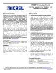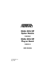
1
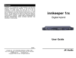
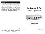
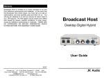
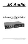
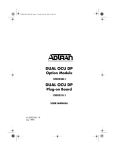
Warranty
Innkeeper 2/4 is covered by a 2-year warranty to be free
from defective workmanship and materials. In the event
that the innkeeper 2/4 needs repair, you must call us to get
an authorization, and then carefully pack and ship it to us.
You will pay for shipping to us and we will pay for return
back to you, UPS ground. No free repairs will be made if
the defect was caused by misuse, weather conditions, or
other cause, except for defective workmanship or materials.
THERE ARE NO EXPRESSED OR IMPLIED
WARRANTIES WHICH EXTEND BEYOND THE
WARRANTY HERE MADE.
innkeeper 2
innkeeper 4
Multi Line Digital Hybrids
User Guide
11/11
JK Audio, Inc. 1311 E 6th Street, Sandwich, IL 60548
USA
Voice: (815) 786-2929 Toll Free: 800-JK-Audio Fax: 815-786-8502
[email protected]
www.jkaudio.com
Copyright © 2007 JK Audio.
All rights reserved.
JK Audio
Introduction
FCC Registration
Innkeeper multi line digital hybrids will allow you to send and
receive audio over analog telephone lines. While this may
seem like a simple task that any telephone can do, the challenge is getting the best quality audio from such a limited audio
path.
What is a Digital Hybrid?
A digital hybrid connects audio signals to a standard analog
telephone line without the variations in quality found with analog hybrids. The main function of a hybrid is to bring in the callers voice from the phone line, as clear and clean as possible. In
the real world, when you send your voice down the telephone
line it has a tendency to bleed over into the caller’s audio. The
hybrid must adapt to the phone line in order to properly separate transmit and receive audio. We use a 16 bit DSP to continuously monitor the phone line and audio signals to deliver
excellent separation. Our dual-convergence algorithm can
achieve excellent trans-hybrid loss, typically exceeding 50 dB,
without any setup.
Ready to go?
The innkeeper 2/4 features diagrams will help you pinpoint any
minor questions that you may have. If this is your first exposure
to a hybrid, we suggest that you read the entire manual to allow
you to take advantage of all these features.
Any Questions?
Before you pick up the phone... Please thumb through the rest
of this manual. You might find those deep technical questions
are covered on later pages.
2
b) The telephone equipment's FCC registration number.
This can be found on the bottom of your telephone
equipment, and
c) the ringer equivalence number (REN) for this equipment.
The REN is used to determine the quantity of devices which
will be connected to the telephone line. Excessive RENs on
the telephone line may result in the devices not ringing in
response to an incoming call. In most, but not all areas, the
sum of the RENs should not exceed 5.0. To be certain of the
number of devices that may be connected to the line, as
determined by the total RENs, contact the local telephone
company.
3. Repair Instructions
If it is determined that your telephone equipment is
malfunctioning, the FCC requires that it not be used and
that it be unplugged from the modular outlet until the
problem has been corrected. Repairs to this telephone
equipment can only be made by the manufacturer or its
authorized agents or by others who may be authorized by
the FCC. For repair procedures, follow the instructions
outlined under the warranty section of the manual.
4. Rights of the telephone company
If telephone equipment is causing harm to the network, the
telephone company may temporarily discontinue your
telephone service. If possible, they'll notify you before they
interrupt service. If advanced notice isn't practical, you'll be
notified as soon as possible. You'll be given the opportunity
to correct the problem, and you'll be informed of your right
to file a complaint with the FCC.
Your telephone company may make changes in its
facilities, equipment, operations or procedures that could
affect the proper functioning of your JK Audio product. If
such changes are planned, you'll be notified by your
telephone company.
19
FCC Part 15 Compliance
Features—Front View
This equipment has been tested and found to comply with the
limits for a Class A digital device, pursuant to Part 15 of the
FCC Rules. These limits are designed to provide reasonable
protection against harmful interference when the equipment is
operated in a commercial environment. This equipment
generates, uses, and can radiate radio frequency energy and,
if not installed and used in accordance with the instruction
manual, may cause harmful interference to radio
communications. Operation of this equipment in a residential
area is likely to cause harmful interference in which case the
user will be required to correct the interference at his own
expense.
Changes or modifications not expressly approved by JK Audio
can void the user's authority to operate the equipment.
FCC Registration
Your new JK Audio product has been registered with the
Federal Communications Commission (FCC). This product
complies with the standards in Part 68 of the FCC rules.
1. Connection and use with the nationwide telephone
network
The FCC requires that you connect this telephone
equipment to the national telephone network through a
USOC RJ-11C modular telephone jack.
This equipment may not be used with Party Line Service or
Coin Telephone Lines.
This equipment is hearing aid compatible.
2. Information for the telephone company
Upon request from your local telephone company, you are
required to provide the following information:
a) The "line" to which you will connect the telephone
equipment (that is, your telephone number), and
18
1
1
2
3 4
5
7 8
6
9
11
10
Backlit LDC menu display, 2x20 characters.
2. Directional Arrow Keys - Press these buttons to navigate through
the menu.
3. Enter Button - Press this button to make a selection on the menu.
4. Keypad - Use these keys to dial a phone number or manually enter menu selection codes.
5. Call Buttons - Press these buttons to take the corresponding
phone line off-hook or manually answer an incoming call.
6. Drop Buttons - Press these buttons to manually drop a call or
place the corresponding phone line on-hook.
7. OH LED - Off-Hook LED lights when the corresponding phone line
is off-hook or on line with a call. Also functions as a visual ring indicator and will flicker when ring voltage is present on the corresponding phone line.
8. Transmit LED - Bi-color Transmit LED will light green when audio
is being sent down the corresponding phone line at -20 dB or
greater signal level. LED will change to red to indicate clipping at
-3 dB.
9. Receive LED - Bi-color Receive LED indicates that caller audio is
present on the corresponding phone line at -20 dB or greater signal level if green and -3 dB or greater if red.
10. Conference button - Use this feature to conference together lines
1 and 2 when both lines are off-hook. This feature is available on
innkeeper 2 only.
11. Monitor Handset Jacks - Used to connect an electret type handset
for communication on the corresponding phone line.
3
Features—Rear View
Specifications
Operation (continued)
12
14
13
16 17
18
15
Inputs:
Line:
Balanced Female XLR, 20k ohm,
+10 dBu max
Master Send:
Balanced Female XLR, 20k ohm,
+10 dBu max
Line:
Balanced Male XLR, 200 ohm,
+14 dBu max
Outputs:
12. Phone Line Jack - RJ-11 phone line jacks for connection to analog phone lines.
13. Auxiliary Phone Jack - RJ-11 phone jacks for connection to analog telephone(s). Telephone(s) connected will only work with corresponding phone line jack. The auxiliary telephone should be
used only for dialing and answering calls.
Handset:
Front panel handset jacks biased
for electret handset (not included)
Phone Line:
RJ-11C
14. Caller XLR - Balanced line level XLR outputs containing Caller
audio from the corresponding phone line.
Aux Phone:
RJ-11C
15. Send XLR - Balanced line level XLR inputs used to send audio
to the corresponding phone line.
Isolation:
1500 VAC
Ringer:
0.5B REN
Frequency Response:
Telephone Side 200 Hz - 3600 Hz
17. Remote Jack - Proprietary 10 pin RJ-50 for connection to a remote terminal interface. The included terminal block features an
Off-Hook signal pin and a Call/Drop control pin for each channel
(See page 8). This jack can also be used for connection to the
optional JK Audio RIU-IP remote interface (see page 16)
Power:
120-240 VAC, 50-60 Hz
Power supply (internal)
Size:
19" x 7.3" x 1.75"
(26.7 x 18.6 x 4.5 cm)
18. AC connector - Connect to 120-240 VAC, 50-60 Hz power outlet.
Weight:
7.2 pounds (3.2 kg)
Remote Connector:
RJ-50, 10 pin
16. Master Send - Balanced line level XLR input may send audio to
any or all of the phone lines based upon controls set within the
menu.
4
17
FAQs
Connection—Mix-Minus Setup
?
!
Can I plug a mic into one of the female XLR jacks?
No, these are line level inputs only.
?
!
How do I adjust signal levels?
Use menu settings to change input and output levels ±10dB.
?
What happens to the phone connection if power is momentarily interrupted?
FCC and International telecom rules require that we drop the
connection if power is lost for any period of time. We strongly
suggest that you use a low cost, computer style UPS system if
uninterrupted service is required.
!
Optional Remote Interface Unit
RIU-IP
The JK Audio Remote Interface Unit was designed for use with innkeeper 2 and innkeeper 4 as well as innkeeper 1x/1rx digital hybrids.
This unit contains a web server which allows the user to send and
receive control data through their web browser. RIU-IP can be connected to the user's computer NIC card for direct control, to a switch
or hub for network control, or to an Ethernet port with internet access
for control from anywhere in the world.
RIU-IP features and capabilities when used with innkeeper 2/4:
• RJ-45 Ethernet port
• RS-232 remote control port with simple ASCII protocol
• No external power required
• Indication of incoming ring per line
• On-Hook and Off-Hook
• Place call on hold or release hold
• Dial (number) (line)
• Auto-Answer on/off, set ring count
• Test tone start / stop per line
• Automatic Gain Control on/off
• Audio level - Send and Receive
• Master Send on/off
• Phone Book updates
• Conference Mode on/off (innkeeper 2 only)
Contact your JK Audio dealer for more information on this product.
16
Auxiliary telephones optional. Used to
dial out to set up calls or to answer calls.
Aux Send 1 to Send 1,
Aux Send 2 to Send 2
Each Caller to any
line level input
Number of mics
depends on mixer
Turn only these
two knobs all the
way down so
this audio does
not go back to
the same caller.
Turn all other
knobs up so
each caller can
hear all mics and
other callers
For whichever input channel you have each Caller connected to, turn the
corresponding Aux control to minimum (usually hard left) so each Caller will
not hear their own audio. Each Aux Send bus is completely separate from
all other outputs, so each row of Aux controls will not affect what is heard
on the Main outputs or on other Aux buses. If possible, the Aux Send buses
should be pre-fader, so you can use the fader controls to set the levels of
each channel to the main output without affecting the audio sent to the
Caller through the Aux Send buses. The innkeeper 2 was used in this example. Follow the same strategy for an innkeeper 4 with 4 Aux Send buses.
5
Operation
Operation
Operation
- Conference
(continued) Options
Connecting Cables
Although each application will require a slightly different setup, the
following is a general cable connection setup and explanation. Using
balanced XLR cables (not included) with 1/4” TRS adapters if necessary for your mixer, make all connections as shown.
Advanced Conference Options Signal Flow Diagrams
• Phone Line - Connect the supplied RJ-11 phone line cable(s) be-
tween the RJ-11 jack(s) marked "Line" and your wall jack(s). Be
sure these jacks can support standard analog telephone operation. The innkeeper 2/4 will not work with "dry pair" phone line connections.
• Send XLR - Connect a line level (mix-minus) audio signal to the
Send jack(s) on the innkeeper 2/4. Audio will be sent down only
the corresponding phone line.
• Master Send XLR - Connect a line level (mix-minus) audio signal
to the Master Send input. Audio will be sent down either or both
phone lines based upon your menu selections.
• Caller XLR - Connect Caller output(s) to line level input(s) on your
audio equipment. Each caller output jack will contain audio only
from its corresponding phone line. Local audio and audio from alternate phone lines will not be present on these jacks. Innkeeper 2
can send isolated caller audio, mixed caller audio, or mixed caller
and local audio from the Caller XLR based on selections made in
the Conferencing menu.
• Power - Connect the supplied power cable to a 110 - 220 VAC
power outlet.
Auxiliary Telephone(s)
You can use an auxiliary telephone to place or screen a call. When
you are ready to take the call on innkeeper 2/4, press the Call button
for the corresponding phone line. That line will now pass through the
digital hybrid. If your telephone has a “Hold” feature, you can answer
the phone and place the call on hold. When you press the “Call” button, the innkeeper will automatically release the hold and connect
that line through the hybrid. If you need to take the call back on the
auxiliary telephone, simply pick up the phone before the innkeeper
2/4 Drop button is pressed for that line.
6
15
Operation - Conference (innkeeper 2 only)
Operation (continued)
Conference
One press of the conference button will join the audio paths of both
line one and line two, provided there are calls present on both lines.
Transmit Signals
The bi-color Transmit LED for each line displays the signal level as it
goes out over the phone line. The LED will display transmit signal
levels at -20 dB as green and indicate clipping at -3 dB as red. The
goal is to drive the phone line at high enough levels to avoid phone
line noise, but not so loud as to cause excessive clipping. Adjust your
Send audio signals to a level slightly less than the point where you
see occasional flashes of red on the Transmit LED. These flashes
should occur during loud speech bursts only. If the Transmit LED
stays lit red for extended periods, you can assume that much of your
speech is being clipped or distorted. In this case you should lower the
audio levels for the signal that is causing the clipping. The innkeeper
2/4 menu will also allow you to adjust your input levels in 1 dB increments over a ±10 dB range.
A second press of the conference button will break the audio paths
between the calls. An auto-dropped or manually dropped line will
automatically break the conference.
By default, line1 send and line send audio will be mixed together
digitally and sent into both phone lines. Line 1 caller will hear line 2
caller audio. Line 2 caller will also hear line 1 caller audio. In the
menu, this configuration is referred to as Send-Mix, Caller-No Mix.
This default configuration is by far the most widely used. Advanced
options are available for Conference mode; however for most situations it will not be necessary to change these default options.
Innkeeper 2 Advanced Conference Options
The factory default conference mode provides both callers with a mix
of Line 1 Send and Line 2 Send audio. Additional mix options can be
found in the Configuration menu. These options allow you to enable
and disable Send and Caller mix features. Keep in mind that no matter what options are selected, both callers will always be able to communicate with each other in Conference mode.
Send = Mix (default)
Line 1 send and Line 2 send audio mixed and sent to both caller lines
Send = No Mix
Line 1 Send audio to line 1 caller
Line 2 Send audio to line 2 caller
Caller = No Mix (default)
Line 1 caller audio only on the Line 1 caller output XLR
Line 2 caller audio only on the Line 2 caller output XLR
Send audio will not be present on these outputs
Caller = Caller Mix
Line 1 and Line 2 caller audio on both of the line 1 and line 2 caller
XLR outputs. Send audio will not be present on these outputs
Caller = Full Mix Minus
A full mix of all audio on each of the caller XLR outputs, minus the
Send audio for that phone line
Line 1 Caller XLR contains Caller 1 + Caller 2 + Send 2
Line 2 Caller XLR contains Caller 1 + Caller 2 + Send 1
14
Receive Signals
The bi-color Receive LED displays the signal coming from the phone
line and out of the DSP. The LED will display receive signal levels at
-20 dB as green up to -3 dB where it will change to red. The innkeeper 2/4 menu will allow you to adjust individual Caller output levels in 1 dB increments over a ±10 dB range to give you the best signal level at your equipment. The Caller level control in the menu will
not change what you see on the Receive LED.
Auto-Answer
The Auto-Answer feature can be activated through the innkeeper 2/4
menu. You may select which phone lines will have auto-answer enabled as well as how many rings before auto-answer. When AutoAnswer is enabled, you can still take calls manually using the call
button. When finished, you can either drop the call manually or allow
the call to auto-disconnect. Innkeeper 2/4 will look for a CPC disconnect signal or ROH message from the phone company to determine
when a call has disconnected. This can take up to a minute.
Remote Jack
The 10 pin RJ-50 jack on the back of the innkeeper 2/4 provides a
proprietary connection to the supplied remote terminal block (see
page 8), using the supplied 1 meter cable. This jack can also be used
to connect to the optional JK Audio RIU-IP remote interface unit (see
page 16).
7
Remote Terminal Block
Serial
Operation
Remote
(continued)
Control Commands
Remote Terminal Block
A Remote Terminal Block has been provided in this package with a
special 1 meter RJ-50 cable for connection to your innkeeper 2/4.
Command
/?
Feature
Help
Value
Status
Comments
Returns Help Menu to screen
/AT or //
Version
Status
Returns product version and status
The Remote Terminal Block includes an Off-Hook signal pin and a
Call/Drop control pin for each phone line channel. The OH signal pin
is current limited to 50 mA, 5 VDC. The control pin toggles the corresponding phone line off-hook/on-hook with a connection/break from
ground. Connecting a Line OH Control pin to the Ground pin will take
that line off-hook; breaking this contact will disconnect the call.
/CF
Config
Status
Returns option configuration settings
/LxST
Line State
On-hook = 0
Off-hook = 1
Ring = 2
Hold = 3
Returns state information for the
specified line
ESC
Escape
/VBn
Verbose
/LxCL
Call Line
Escape current command before execution
Sets varying levels of Verbose mode
from no echo of response (VB0),
abbreviated echo (VB1 or VB2) or
full echo (VB3)
Off-hook line control for each line
/LxDR
Drop Line
On-hook line control for each line
/LxAAv
/LxARv
Auto-Answer
mode
Ring Count
Off=0
ON=1
RING CNT=v
/LxHDv
Line Hold
/LxSLv
Send Level
Off=0
HOLD=1
-10 to +10
/LxRLv
Receive
Level
Dial phone
number
This terminal block was designed to allow remote off-hook/on-hook
control and status for each phone line. The innkeeper 2 model also
provides on/off control and status for the Conference feature. Use
only the included RJ-50 cable to connect the Remote Terminal Block
to the Remote jack on the innkeeper 2/4.
The OH Status pin will provide 5V, 50mA when the corresponding
line is off-hook. You can use this to drive a relay, light an LED, etc.
NOTE: Installation of jumper J5 will set “static” OH line control, so that a steady ground
on any control input will take the corresponding line off-hook, otherwise the line will remain on-hook. Removal of jumper J5 will return OH line control to its original “momentary”
control mode, so that any line control input that is momentarily brought to ground (for a
min. of 100ms), will toggle/switch the corresponding line state between on-hook or offhook as determined by the given line’s previous state.
Terminal Block Pinout
1
GRD
2
3
L1-ST L1-CNT
Terminal
Number
1
2
3
4
5
6
7
8
9
10
4
5
6
7
8
9
10
L2-ST
L2-CNT
L3-ST
L3-CNT
L4-ST
L4-CNT
GND
Terminal Description
Ground
Line 1 - OH status signal
Line 1 - OH control *
Line 2 - OH status signal
Line 2 - OH control *
Line 3 - OH status signal
Line 3 - OH control *
Line 4 - OH status signal
Line 4 - OH control *
Ground
J5
J5
momentary
mode
static
mode
* momentary or static line
control selection for all lines
is made via jumper J5 on
the main circuit board.
Jumper open = momentary
Jumper closed = static
8
/LxDIy
VB0
VB1
VB2
VB3
-10 to +10
Digit string
/CNv
Conference
OFF=0
ON=1
/PBv
Phone Book
Upload /
Download
UPLD=0
DNLD=1
/PEv
Phone Book
View / Add /
Delete Entry
Master Send
TBD
/LxMSv
OFF=0
ON=1
Activate/deactivate auto-answer
mode for each line
Set auto-answer ring count from 1-7
rings per line (default is 3)
Place specified line on hold or release hold
Set send (transmit) audio level for
specified line from -10 to +10dBu
Set caller (receive) audio level for
specified line from -10 to +10dBu
Dial phone number on selected line,
up to 20 digits (line will automatically go off-hook)
innkeeper 2 only. Conference both
phone lines together
(both lines must be off-hook first)
Upload/download entire phonebook
entry list (20 characters per name
and 20 digits per phone number for
each entry) from/to ASCII file on
user PC and innkeeper 2/4
Manipulate individual phone book
entries
Activate/deactivate master send
mode for each line
13
Multi-Tap Key Legend
Operation
Operation- Menu
(continued)
Display
These character sets are active only when entering the Name of your phone
book entry. While entering the phone number you will not have access to
alpha characters.
Menu Display and Configuration Controls
The innkeeper 2/4 menu is controlled by the directional arrows, alpha
numeric keypad and Enter button. You may use either the arrow keys
to scroll through the menus or the keypad to directly select menus
and use the Enter button or the keypad to make your selections.
Through the menu you have access to the following configuration
settings. The () indicate the numeric entry used to access these
menus without scrolling. For example, to access the Call History
View menu directly, you would press 2, Enter, 1, Enter.
Control Keys:
<
>
*
#
Character Keys:
1
2
3
4
5
6
7
8
9
Clear last character
Next / Accept current character
Shift (press before each uppercase entry)
Space
. @ ? ! - \ , & : | 1
a b c 2
d e f 3
g h i 4
j k l 5
m n o 6
p q r s 7
t u v 8
w x y z 9
Serial Remote Control Commands
The ASCII commands listed on the following page can be entered through
the serial port on your computer by using the DB9 connector on the RIU.
Any terminal emulation program on your computer,
such as HyperTerminal, can be accessed using these parameters:
Baud rate = 9600
Stop bits = 1
Parity = none
Flow control = none
Notes: All commands begin with the ‘/’ character and will be executed on
next ‘/’or ‘Enter’.
The line number is set to ‘1’ by default and is changed by using the ‘Lx”
parameter with the specified control command.
x specifies the line number (1 to 4)
v specifies the parameter value to be used for the command
y specifies the digit string used during manual dialing mode
Status information is automatically returned during incoming state changes
for the specified line number for the following line conditions: on-hook,
off-hook, incoming ring, and line hold.
12
Phone Book (1) A 50 entry name and number phone book for storing speed dial numbers.
Phone Book View (1,1) Allows you to view name and phone numbers of added entries. You may dial the selected entry from this
menu by simply pressing the Call button on any phone line.
Phone Book Add Entry (1,2) You may add new entries from this
menu. After pressing Enter you will be prompted for the phone number. You may enter a 2 second pause in your phone number entry by
pressing the > key. Multiple > key presses will enter multiple 2 second pauses. The display will show a "." between the numbers for
each 2 second pause entered. After the Enter key is pressed again
you will be prompted for the entry Name. Alpha characters may be
selected by using the multi-tap feature. For example, to enter the
character "a" you would press the 2 key. To enter "b" you would
press the 2 key twice. Hitting a new key, the Next> key or waiting 2
seconds will accept the current character and move the cursor forward. See page 10 for multi-tap key legend.
Phone Book Delete Entry (1,3) Entries may be deleted individually
from this menu. You will be prompted to confirm delete of an entry.
Phone Book Clear (1,4) Press enter from this menu to clear all
phone book entries. You will be prompted to confirm your intent to
clear the entire phone book before deletion.
Call History (2) Calls you place will automatically be entered into the
Call History menu. The Call History menu will hold up to 16 numbers.
9
Operation - Menu Display (continued)
Operation - Menu Display (continued)
Call History View (2,1) Allows you to view name and phone numbers of automatically added entries. You may dial the selected entry
from this menu by simply pressing the Call button on any phone line.
Conference (3,5) innkeeper 2 only. This menu allows you to configure settings for the Conference feature. See pages 14-15.
Call History Clear (2,2) Press Enter from this menu to clear all automatically added history entries. You will be prompted to confirm your
intent to clear the entire call history before deletion.
Config. (3) This menu allows you to control Auto-Answer, AutoDisconnect, Audio Levels, Master Send, Calibration, Conferencing
and Restore Factory Default or Custom Settings.
Config. Auto-Answer (3,1) Here you can configure Auto-Answer.
Config. Auto-Answer On/Off (3,1,1) This menu allows you to turn
Auto-Answer on and off for each line independently or for all lines.
Config. Auto-Answer Ring Count (3,1,2) Select the number of rings
before the unit auto-answers on each line individually or on all lines.
Config. Audio Levels (3,2) Audio levels for each phone line input
and output can be set here. The Audio Levels menu allows you to
adjust audio in 1 dB increments over a ±10 dB range. You may adjust
the levels of the Send inputs as well as the Caller outputs.
Config. Audio Levels Send (3,2,1) Send input levels can be set for
each line individually or all lines. These settings affect the independent Send input as well as the Master Send for the selected line(s).
Config. Audio Levels Caller (3,2,2) Caller output levels can be set
here for each line independently or all lines.
Config. Master Send (3,3) This menu gives you the ability to turn the
Master Send on or off for each line individually or all phone lines.
Conf. Send Mix Mode (3,5,1) innkeeper 2 only. Configure the Send
Mix Mode to "Send Mix" default or "No Mix". The "Send Mix" default
option mixes both the Line 1 Send and Line 2 Send audio signals together and sends that audio down both phone lines. The "No Mix"
option does not mix these signals together. Line 1 Send audio will
only go to Phone Line 1 and Line 2 Send audio will only go to Line 2.
You may still use the Master Send input to send a common audio signal to both phone lines.
Conf. Caller Mix Mode (3,5,2) innkeeper 2 only. Configure the Caller
Mix Mode to "No Mix" default, "Caller Mix" or "Full Mix Minus". The
"No Mix" option does not mix any audio together on the Caller output
jacks. Caller 1 out will contain Line 1 Caller audio and Caller 2 out will
contain Line 2 Caller audio. The "Caller Mix" option mixes together
both caller audio signals on both Caller output jacks. Caller 1 and
Caller 2 outputs will contain both Line 1 and Line 2 caller audio. The
"Full Mix Minus" option provides a mix-minus signal output on both
Caller output jacks. Caller 1 out will contain Line 1 caller audio, Line 2
caller audio and Send 2 audio. Caller 2 out will contain Line 1 caller
audio, Line 2 caller audio and Send 1 audio.
Config. Presets (3,6) With this menu you can save and restore custom presets or reset the unit to factory default presets.
Config. Presets - Default (3,6,1) Here you may restore factory default presets. You will be prompted to confirm Factory Reset after selecting this option.
Config. Presets - Custom (3,6,2) Here you may save and restore
custom presets based upon your current configuration.
Config. Calibration (3,4) Here you can send a 1kHz test tone down
the phone line(s) and the output jacks. You may turn the tone on or
off for each line individually or for all lines. This is not required for setting the null. This tone is only for your convenience in setting your
equipment audio levels.
10
11