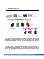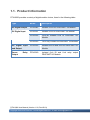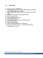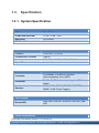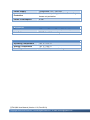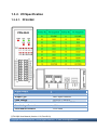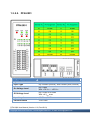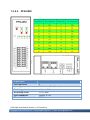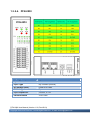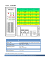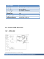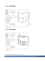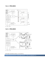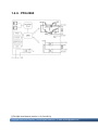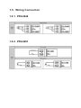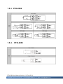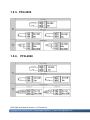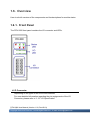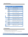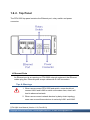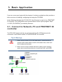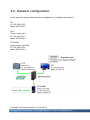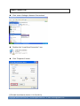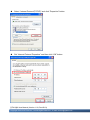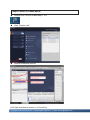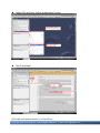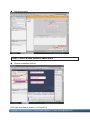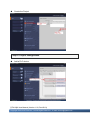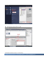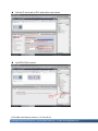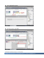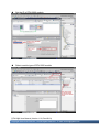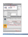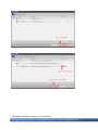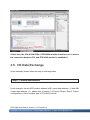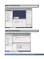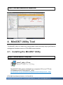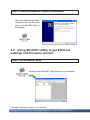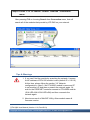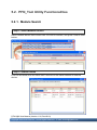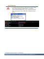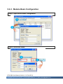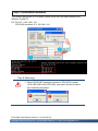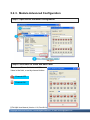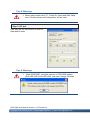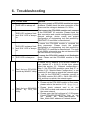
1
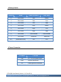
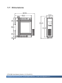
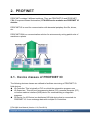
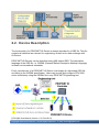
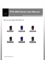
PFN-2000 Series User Manual Version 1.20, Dec 2013 Service and usage information for PFN-2042 PFN-2051 PFN-2052 PFN-2053 PFN-2055 PFN-2060 Written by Raiden Lan Warranty All products manufactured by ICP DAS are under warranty regarding defective materials for a period of one year, beginning from the date of delivery to the original purchaser. Warning ICP DAS assumes no liability for any damage resulting from the use of this product.ICP DAS reserves the right to change this manual at any time without notice. The information furnished by ICP DAS is believed to be accurate and reliable. However, no responsibility is assumed by ICP DAS for its use, not for any infringements of patents or other rights of third parties resulting from its use. Copyright Copyright @ 2013 by ICP DAS Co., Ltd. All rights are reserved. Trademark The names used for identification only may be registered trademarks of their respective companies. Contact US If you have any problem, please feel free to contact us. You can count on us for quick response. Email: [email protected] PFN-2000 User Manual (Version 1.20, Dec/2013) Page: 2 Copyright © 2013 ICP DAS Co., Ltd. All Rights Reserved. E-mail: [email protected] Table of Contents Table of Contents ...................................................................................3 1. Introduction ........................................................................................5 1.1. Product Information ...................................................................................... 6 1.2. Features ....................................................................................................... 7 1.3. Specification ................................................................................................. 8 1.3.1. System Specification .......................................................................... 8 1.3.2. I/O Specification ............................................................................... 10 1.3.2.1. PFN-2042............................................................................... 10 1.3.2.2. PFN-2051................................................................................11 1.3.2.3. PFN-2052............................................................................... 12 1.3.2.4. PFN-2053............................................................................... 13 1.3.2.5. PFN-2055............................................................................... 14 1.3.2.6. PFN-2060............................................................................... 16 1.4. Internal I/O Structure .................................................................................. 17 1.4.1. PFN-2042 ......................................................................................... 17 1.4.2. PFN-2051 ......................................................................................... 18 1.4.3. PFN-2052 ......................................................................................... 18 1.4.4. PFN-2053 ......................................................................................... 19 1.4.5. PFN-2055 ......................................................................................... 19 1.4.6. PFN-2060 ......................................................................................... 20 1.5. Wiring Connection ...................................................................................... 21 1.5.1. PFN-2042 ......................................................................................... 21 1.5.2. PFN-2051 ......................................................................................... 21 1.5.3. PFN-2052 ......................................................................................... 22 1.5.4. PFN-2053 ......................................................................................... 22 1.5.5. PFN-2055 ......................................................................................... 23 PFN-2000 User Manual (Version 1.20, Dec/2013) Page: 3 Copyright © 2013 ICP DAS Co., Ltd. All Rights Reserved. E-mail: [email protected] 1.5.6. PFN-2060 ......................................................................................... 23 1.6. Overview .................................................................................................... 24 1.6.1. Front Panel....................................................................................... 24 1.6.2. Top Panel ......................................................................................... 26 1.7. Dimensions................................................................................................. 28 2. PROFINET .........................................................................................29 2.1. Device classes of PROFINET IO................................................................ 29 2.2. Device Description...................................................................................... 30 2.3. Conformance Classes (CC)........................................................................ 31 3. Basic Application .............................................................................32 3.1. Connect to Network, PC and PROFINET IO controller............................... 32 3.2. Network configuration................................................................................. 33 3.3. GSD Import ................................................................................................ 40 3.4. Project Setup.............................................................................................. 42 3.5. I/O Data Exchange ..................................................................................... 50 4. MiniOS7 Utility Tool..........................................................................52 4.1. Installing the MiniOS7 Utility ....................................................................... 52 4.2. Using MiniOS7 Utility to get Ethernet settings and firmware version .......... 53 5. PFN_Tool Utility ................................................................................55 5.1. Installing the PFN_Tool Utility ..................................................................... 55 5.2. PFN_Tool Utility Functionalities .................................................................. 56 5.2.1. Module Search ................................................................................. 56 5.2.2. Module Basic Configuration.............................................................. 58 5.2.3. Module Advanced Configuration....................................................... 60 6. Troubleshooting ...............................................................................62 PFN-2000 User Manual (Version 1.20, Dec/2013) Page: 4 Copyright © 2013 ICP DAS Co., Ltd. All Rights Reserved. E-mail: [email protected] 1. Introduction PROFINET is an open Industrial Ethernet standard developed by the PROFIBUS Organization (PI). Based on Ethernet versatility, PROFINET make vertical integration of field level with Enterprise level easily. PROFINET is automation in real time, so it can cover all requirements of the Automation Industry. PROFINET is fit for factory automation, process automation, safety applications and motion control applications, etc. PROFINET contains 2 different solutions. They are PROFINET IO and PROFINET CBA (Component Based Automation). PFN-2000 series modules are PROFINET IO devices. The user can access and configure the modules easily by using the GSDML file in any PROFINET Engineering tool, and exchange process data quickly with the IO controller. PFN-2000 User Manual (Version 1.20, Dec/2013) Page: 5 Copyright © 2013 ICP DAS Co., Ltd. All Rights Reserved. E-mail: [email protected] 1.1. Product Information PFN-2000 provides a variety of digital module choice, listed in the following table. Type Model Description DC Digital Output PFN-2042 Isolated 16-ch DO PROFINET I/O Module DC Digital Input PFN-2051 Isolated 16-ch DI PROFINET I/O Module PFN-2052 Ch-to-ch Isolated 8-ch DI PROFINET I/O Module PFN-2053 16-ch Dry Contact DI PROFINET I/O Module DC Digital Input and Output PFN-2055 Isolated 8-ch DI and 8-ch DO PROFINET I/O Module Power Output PFN-2060 Isolated 6-ch DI and 6-ch relay output PROFINET I/O Module Relay PFN-2000 User Manual (Version 1.20, Dec/2013) Page: 6 Copyright © 2013 ICP DAS Co., Ltd. All Rights Reserved. E-mail: [email protected] 1.2. Features Transfer protocol: PROFINET IO Supported Ethernet services: ICMP, IGMP, ARP, DHCP, TELNET, TFTP, SNMP, VLAN Priority Tagging Supported PROFINET services: RTC, RTA, CL-RPC, DCP, LLDP, I&M PROFINET Conformance Class B and RT Class 1 Cyclic Time: 1ms (min) Generic GSDML File Provided Integrated 2-Port Switch Automatic MDI / MDI-X Crossover for Plug-and-play Provide LED indicators Robust, fan less design 4 kV Contact ESD protection for any terminal Wide range of power input (+10 ~ +30 VDC) and operating temperature (-25 ~ +75°C) PFN-2000 User Manual (Version 1.20, Dec/2013) Page: 7 Copyright © 2013 ICP DAS Co., Ltd. All Rights Reserved. E-mail: [email protected] 1.3. Specification 1.3.1. System Specification Hardware CPU 32-bit CPU Core RAM/Flash/EEPROM 32 MB / 4 MB / 8 KB Watchdog CPU built-in ESD Protection 4 kV class A PROFINET Interface Protocol PROFINET IO Device Conformance Classes Class B Services RTC, RTA, CL-RPC, DCP, LLDP, I&M Cycle Time 1 ms (min) Ethernet Interface Controller Connector Services 10/100Base-TX Ethernet Controller (Auto-negotiating, Auto_MDIX) RJ-45 x 2 (LED indicators) , Integrated 2-Port Switch ICMP, IGMP, ARP, DHCP, TELNET, TFTP, SNMP, VLAN Priority Tagging LED Display Round LED PWR LED, S1A LED, S1B LED, S2A LED, S2B LED Power Requirements PFN-2000 User Manual (Version 1.20, Dec/2013) Page: 8 Copyright © 2013 ICP DAS Co., Ltd. All Rights Reserved. E-mail: [email protected] Power supply Unregulated +10 ~ +30 VDC Protection Power reverse polarity protection, Over-voltage brown-out protection Power Consumption 4.5W Mechanical Dimensions 123 mm x 72 mm x 35 mm (W x L x H) Installation DIN Rail or Wall mounting Environment Operating Temperature -25 ˚C ~ +75 ˚C Storage Temperature -30 ˚C ~ +80 ˚C Humidity 10~ 90 % RH, non-condensing PFN-2000 User Manual (Version 1.20, Dec/2013) Page: 9 Copyright © 2013 ICP DAS Co., Ltd. All Rights Reserved. E-mail: [email protected] 1.3.2. I/O Specification 1.3.2.1. PFN-2042 Digital Output Output Channels 16 Output Type Sink, Open Collector Load Voltage +3.5 V DC ~ +50 V DC Max. Load Current 700 mA/channel at 25 °C Over-Voltage Protection +60 V DC Intra-module Isolation 3750 Vrms PFN-2000 User Manual (Version 1.20, Dec/2013) Page: 10 Copyright © 2013 ICP DAS Co., Ltd. All Rights Reserved. E-mail: [email protected] 1.3.2.2. PFN-2051 Digital Input Input Channels 16 Input Type Dry Contact (Source), Wet Contact (Sink, Source) On Voltage Level Dry: Open Wet: +10 V DC ~ +50 V DC Off Voltage Level Dry: Close to DI.GND Wet: +4 V DC max. Input Impedance 10 kOhm, 0.5 W Photo-Isolation 3750 Vrms PFN-2000 User Manual (Version 1.20, Dec/2013) Page: 11 Copyright © 2013 ICP DAS Co., Ltd. All Rights Reserved. E-mail: [email protected] 1.3.2.3. PFN-2052 Digital Input Input Channels 8 Input Type Wet Contact (Sink, Source) On Voltage Level +4 V DC ~ 30 V DC Off Voltage Level +1 V DC max. Input Impedance 3 kOhm, 0.3 W Photo-Isolation 3750 Vrms PFN-2000 User Manual (Version 1.20, Dec/2013) Page: 12 Copyright © 2013 ICP DAS Co., Ltd. All Rights Reserved. E-mail: [email protected] 1.3.2.4. PFN-2053 Digital Input Input Channels 16 Input Type Dry Contact (Source) On Voltage Level Close to DI.GND Off Voltage Level Open Input Impedance 3 kOhm, 0.3 W Photo-Isolation 3750 Vrms PFN-2000 User Manual (Version 1.20, Dec/2013) Page: 13 Copyright © 2013 ICP DAS Co., Ltd. All Rights Reserved. E-mail: [email protected] 1.3.2.5. PFN-2055 Digital Input Input Channels 8 Input Type Dry Contact (Source), Wet Contact (Sink, Source) On Voltage Level Dry: Close to DI.GND Wet: +10 V DC ~ +50 V DC Off Voltage Level Dry: Open Wet: +4 V DC max. Input Impedance 10 kOhm, 0.5 W Photo-Isolation 3750 Vrms PFN-2000 User Manual (Version 1.20, Dec/2013) Page: 14 Copyright © 2013 ICP DAS Co., Ltd. All Rights Reserved. E-mail: [email protected] Digital Output Output Channels 8 Output Type Sink, Open Collector Output Voltage +3.5 Max. Load Current 700 mA/channel at 25 °C Direct drive power relay module Over-Voltage Protection +60 V DC Intra-module Isolation 3750 Vrms VDC ~ +50 V DC PFN-2000 User Manual (Version 1.20, Dec/2013) Page: 15 Copyright © 2013 ICP DAS Co., Ltd. All Rights Reserved. E-mail: [email protected] 1.3.2.6. PFN-2060 Digital Input Input Channels 6 Input Type Dry Contact (Source), Wet Contact (Sink, Source) On Voltage Level Dry: Close to DI.GND Wet: +10 V DC ~ +50 V DC Off Voltage Level Dry: Open Wet: +4 V DC max. Input Impedance 10 kOhm, 0.5 W Photo-Isolation 3750 Vrms PFN-2000 User Manual (Version 1.20, Dec/2013) Page: 16 Copyright © 2013 ICP DAS Co., Ltd. All Rights Reserved. E-mail: [email protected] Digital Output Output Channels 6 Output Type Power Relay, Form A x 6 Contact Rating AC: 125 [email protected] DC: 30V@2A, [email protected] Operating Time 3 ms Release Time 2 ms Total Switching Time 10 ms Surge Strength 500 V AC (50/60 Hz) Insulation resistance 1000 MW min. at 500 V DC 1.4. Internal I/O Structure 1.4.1. PFN-2042 PFN-2000 User Manual (Version 1.20, Dec/2013) Page: 17 Copyright © 2013 ICP DAS Co., Ltd. All Rights Reserved. E-mail: [email protected] 1.4.2. PFN-2051 1.4.3. PFN-2052 PFN-2000 User Manual (Version 1.20, Dec/2013) Page: 18 Copyright © 2013 ICP DAS Co., Ltd. All Rights Reserved. E-mail: [email protected] 1.4.4. PFN-2053 1.4.5. PFN-2055 PFN-2000 User Manual (Version 1.20, Dec/2013) Page: 19 Copyright © 2013 ICP DAS Co., Ltd. All Rights Reserved. E-mail: [email protected] 1.4.6. PFN-2060 PFN-2000 User Manual (Version 1.20, Dec/2013) Page: 20 Copyright © 2013 ICP DAS Co., Ltd. All Rights Reserved. E-mail: [email protected] 1.5. Wiring Connection 1.5.1. PFN-2042 1.5.2. PFN-2051 1.5.3. PFN-2052 1.5.4. PFN-2053 PFN-2000 User Manual (Version 1.20, Dec/2013) Page: 22 Copyright © 2013 ICP DAS Co., Ltd. All Rights Reserved. E-mail: [email protected] 1.5.5. PFN-2055 1.5.6. PFN-2060 PFN-2000 User Manual (Version 1.20, Dec/2013) Page: 23 Copyright © 2013 ICP DAS Co., Ltd. All Rights Reserved. E-mail: [email protected] 1.6. Overview Here is a brief overview of the components and its descriptions for module status. 1.6.1. Front Panel The PFN-2000 front panel contains the I/O connector and LEDs. I/O Connector Depending on the types of the PFN-2000 modules. For more detailed information regarding the pin assignments of the I/O Connector, please refer to “1.3.2. I/O Specification” PFN-2000 User Manual (Version 1.20, Dec/2013) Page: 24 Copyright © 2013 ICP DAS Co., Ltd. All Rights Reserved. E-mail: [email protected] Status LED Indicators Name LED Action Description ON The power supply is OK. OFF The power supply is failed. PWR A=ON Device is at Run mode. B=OFF A=ON Device is at Bootloader mode. B=ON S1 A=ON Device is at Run mode and the module B=Flash received the incorrect parameters. A=Flash Receive a Flash LED command. B=Any A=OFF B=ON Bootloader mode: Ethernet link established, waiting for IP address acquired A=OFF Bootloader mode: waiting for Ethernet link B=Flash Run mode: waiting for Profinet connection S2 A=ON The connection is established. B=OFF A=Flash B=OFF Bootloader mode: IP address acquired, waiting for telnet connection I/O LED Indicators Depending on the types of the PFN-2000 modules. For more detailed information, please refer to “1.3.2. I/O Specification” PFN-2000 User Manual (Version 1.20, Dec/2013) Page: 25 Copyright © 2013 ICP DAS Co., Ltd. All Rights Reserved. E-mail: [email protected] 1.6.2. Top Panel The PFN-2000 top panel contains the Ethernet port, rotary switch and power connector. Ethernet Ports An Ethernet port is an opening on PFN-2000 network equipment that Ethernet cables plug into. Ethernet ports accept cables with RJ-45 connectors. Tips & Warnings 1. When users connect PFN-2000 and switch, users should not connect LAN1 and LAN2 to switch at the same time, else it will lead to abnormal network. 2. When users connect network devices by daisy chain topology, users can connect these devices in series by LAN1 and LAN2. PFN-2000 User Manual (Version 1.20, Dec/2013) Page: 26 Copyright © 2013 ICP DAS Co., Ltd. All Rights Reserved. E-mail: [email protected] Rotary Switch Position Mode Power ON Value Safe Value 0 Run mode Low Retain 1 Run mode Low Low 2 Run mode Low High 3 Run mode High Retain 4 Run mode High Low 5 Run mode High High 6 Run mode User Defined User Defined 7 Run mode Reserved Reserved 8~F Bootloader mode N/A N/A Power Connector Pin Name Function +VS 10 ~ 30 VDC power input GND Ground connection F.G. Frame ground connection PFN-2000 User Manual (Version 1.20, Dec/2013) Page: 27 Copyright © 2013 ICP DAS Co., Ltd. All Rights Reserved. E-mail: [email protected] 1.7. Dimensions PFN-2000 User Manual (Version 1.20, Dec/2013) Page: 28 Copyright © 2013 ICP DAS Co., Ltd. All Rights Reserved. E-mail: [email protected] 2. PROFINET PROFINET contains 2 different solutions. They are PROFINET IO and PROFINET CBA (Component Based Automation). PFN-2000 series modules are PROFINET IO devices. PROFINET IO is used for communication with decentral periphery like IOs, drives, etc. PROFINET CBA is a communication solution for autonomously acting partial units of machines or plants. 2.1. Device classes of PROFINET IO The following devices classes are defined to facilitate structuring of PROFINET IO field devices. IO-Controller: This is typically a PLC on which the automation program runs IO-Supervisor: This can be a programming device (PG), personal computer (PC), or human machine interface (HMI) device for commissioning or diagnostic purposes. IO-Device: An IO-Device is a distributed I/O field device that is connected via PROFINET IO. It can exchange data with multiple IO-Controllers. PFN-2000 User Manual (Version 1.20, Dec/2013) Page: 29 Copyright © 2013 ICP DAS Co., Ltd. All Rights Reserved. E-mail: [email protected] 2.2. Device Description The functionality of a PROFINET IO Device is always described in a GSD file. This file contains all data that are relevant for engineering as well as for data exchange with IO-Device. PROFINET IO-Devices can be described using XML-based GSD. The description language of the GSD file, i.e. GSDML (General Station Description Markup Language) is based on international standards. Every manufacturer of a PROFINET IO-Device must supply an associated GSD file according to the GSDML specification. Users can access and configure PFN-2000 series modules by using the GSDML file in any PROFINET Engineering tool. PFN-2000 User Manual (Version 1.20, Dec/2013) Page: 30 Copyright © 2013 ICP DAS Co., Ltd. All Rights Reserved. E-mail: [email protected] 2.3. Conformance Classes (CC) PI has classified the scope of functions in PROFINET IO into 3 conformance classes (CC-A, CC-B, CC-C). Users simply need to select a CC appropriate for system and do not need to worry about any other details to ensure the interoperability in an automation system with regard to the scope of functions and performance parameters. CC-A: Use of the infrastructure of an existing Ethernet network including integration of basic PROFINET functionality. All IT services can be used without restrictions. Examples of typical applications are in building automation and process automation. Wireless communication is only possible in this class. CC-B: In addition to the functions of CC-A, the scope of functions of CC-B supports easy and user-friendly device replacement without the need for an engineering tool. Examples of typical applications are in automation systems with a higher-level machine controller that place relatively low demands for a deterministic data cycle. CC-C: In addition to the functions of CC-B, the scope of functions of CC-C supports high-precision and deterministic data transmission, including for isochronous applications. An example of a typical application is the field of motion control. PFN-2000 User Manual (Version 1.20, Dec/2013) Page: 31 Copyright © 2013 ICP DAS Co., Ltd. All Rights Reserved. E-mail: [email protected] 3. Basic Application If you are a new user, begin with this chapter, it includes a guided tour that provides a basic overview of installing, configuring and using the PFN-2000. In the following examples the S7-1200 PLC from Siemens is used to be a PROFINET IO Controller. The configuration and communication is done by the program “Step 7 V11 SP2 (TIA PORTAL)” provided by Siemens. 3.1. Connect to Network, PC and PROFINET IO controller The PFN-2000 series modules are equipped with two RJ-45 Ethernet ports for connection to an Ethernet switch, PC and PROFINET IO controller. Tips & Warnings 1. When users connect PFN-2000 and switch, users should not connect LAN1 and LAN2 to switch at the same time, else it will lead to abnormal network. 2. When users connect network devices by daisy chain topology, users can connect these devices in series by LAN1 and LAN2. 3.2. Network configuration In this example, please follow the below configuration to configure the network. PC: IP: 192.168.6.210 Mask: 255.255.0.0 PLC: Device name: plc1 IP: 192.168.6.211 Mask: 255.255.0.0 PFN-2000: Device name: pfn-2000 IP: 192.168.6.212 Mask: 255.255.0.0 PFN-2000 User Manual (Version 1.20, Dec/2013) Page: 33 Copyright © 2013 ICP DAS Co., Ltd. All Rights Reserved. E-mail: [email protected] Step 1: Set PC’s IP Click “start->Settings->Network Connections” Double click “Local Area Connection” icon Click “Properties” button PFN-2000 User Manual (Version 1.20, Dec/2013) Page: 34 Copyright © 2013 ICP DAS Co., Ltd. All Rights Reserved. E-mail: [email protected] Select “Internet Protocol(TCP/IP)” and click “Properties” button Set “Internet Protocol Properties” and then click “OK” button. PFN-2000 User Manual (Version 1.20, Dec/2013) Page: 35 Copyright © 2013 ICP DAS Co., Ltd. All Rights Reserved. E-mail: [email protected] Step 2: Set PLC’s name and IP Double Click TIA icon to start Step 7 V11 Click “Project view” Search accessible devices PFN-2000 User Manual (Version 1.20, Dec/2013) Page: 36 Copyright © 2013 ICP DAS Co., Ltd. All Rights Reserved. E-mail: [email protected] Select PLC and click “Online & diagnostics” button Set IP and Mask PFN-2000 User Manual (Version 1.20, Dec/2013) Page: 37 Copyright © 2013 ICP DAS Co., Ltd. All Rights Reserved. E-mail: [email protected] Set device name Step 3: Set PFN-2000 module’s name and IP Search accessible devices PFN-2000 User Manual (Version 1.20, Dec/2013) Page: 38 Copyright © 2013 ICP DAS Co., Ltd. All Rights Reserved. E-mail: [email protected] Select PFN-2000 module and click “Online & diagnostics” button Set IP and Mask PFN-2000 User Manual (Version 1.20, Dec/2013) Page: 39 Copyright © 2013 ICP DAS Co., Ltd. All Rights Reserved. E-mail: [email protected] Set device name 3.3. GSD Import In this example, please follow the step to import GSD file. Step 1: Get GSD file The GSD file can be obtained from companion CD or our FTP site: CD: \fieldbus_cd\profinet\remote io\pfn-2000\gsd\ ftp://ftp.icpdas.com/pub/cd/fieldbus_cd/profinet/remote%20io/pfn-2000/gsd/ Step 2: Import GSD file Double Click TIA icon to start Step 7 V11 PFN-2000 User Manual (Version 1.20, Dec/2013) Page: 40 Copyright © 2013 ICP DAS Co., Ltd. All Rights Reserved. E-mail: [email protected] Click “Project view” Select “Menu->Options->Install general station description file (GSD)” PFN-2000 User Manual (Version 1.20, Dec/2013) Page: 41 Copyright © 2013 ICP DAS Co., Ltd. All Rights Reserved. E-mail: [email protected] Select and install GSD file 3.4. Project Setup In this example, please follow the step to setup project. Step 1: Create the project Double Click TIA icon to start Step 7 V11 PFN-2000 User Manual (Version 1.20, Dec/2013) Page: 42 Copyright © 2013 ICP DAS Co., Ltd. All Rights Reserved. E-mail: [email protected] Create the Project Step 2: Project configuration Add a PLC device PFN-2000 User Manual (Version 1.20, Dec/2013) Page: 43 Copyright © 2013 ICP DAS Co., Ltd. All Rights Reserved. E-mail: [email protected] Set the device name of PLC to “plc1” PFN-2000 User Manual (Version 1.20, Dec/2013) Page: 44 Copyright © 2013 ICP DAS Co., Ltd. All Rights Reserved. E-mail: [email protected] Set the IP and mask of PLC and add a new subnet Add PFN-2000 module PFN-2000 User Manual (Version 1.20, Dec/2013) Page: 45 Copyright © 2013 ICP DAS Co., Ltd. All Rights Reserved. E-mail: [email protected] Select PROFINET interface Set device name to “pfn-2000” PFN-2000 User Manual (Version 1.20, Dec/2013) Page: 46 Copyright © 2013 ICP DAS Co., Ltd. All Rights Reserved. E-mail: [email protected] Set the IP of PFN-2000 module Select module type of PFN-2000 module PFN-2000 User Manual (Version 1.20, Dec/2013) Page: 47 Copyright © 2013 ICP DAS Co., Ltd. All Rights Reserved. E-mail: [email protected] Compile and download to device PFN-2000 User Manual (Version 1.20, Dec/2013) Page: 48 Copyright © 2013 ICP DAS Co., Ltd. All Rights Reserved. E-mail: [email protected] PFN-2000 User Manual (Version 1.20, Dec/2013) Page: 49 Copyright © 2013 ICP DAS Co., Ltd. All Rights Reserved. E-mail: [email protected] At this time, the S1A & S2A LEDs of PFN-2000 module should turn on, it means the connection between PLC and PFN-2000 module is established. 3.5. I/O Data Exchange In this example, please follow the step to exchange data. Step 1: Confirm data address In this example, the pfn-2055 module address is IB1 (input data address = 1) and QB1 (output data address = 1), please refer to section 3.4 Project Setup=> Step 2: Project configuration=> Select module type of PFN-2000 module. PFN-2000 User Manual (Version 1.20, Dec/2013) Page: 50 Copyright © 2013 ICP DAS Co., Ltd. All Rights Reserved. E-mail: [email protected] Step 2: Add a new watch table Step 2: Input IB & QB address PFN-2000 User Manual (Version 1.20, Dec/2013) Page: 51 Copyright © 2013 ICP DAS Co., Ltd. All Rights Reserved. E-mail: [email protected] Step 3: Get input data and set output data 4. MiniOS7 Utility Tool The MiniOS7 Utility is a useful tool that provides a quick and easy way to get Ethernet settings and firmware version of PFN-2000 series modules. 4.1. Installing the MiniOS7 Utility Step 1: Get the MiniOS7 Utility tool The MiniOS7 Utility can be obtained from companion CD or our FTP site: CD:\Napdos\minios7\utility\minios7_utility\ ftp://ftp.icpdas.com/pub/cd/8000cd/napdos/minios7/utility/minios7_utility/ PFN-2000 User Manual (Version 1.20, Dec/2013) Page: 52 Copyright © 2013 ICP DAS Co., Ltd. All Rights Reserved. E-mail: [email protected] Step 2: Follow the prompts to complete the installation After the installation has been completed, there will be a new short-cut for MiniOS7 Utility on the desktop. 4.2. Using MiniOS7 Utility to get Ethernet settings and firmware version Step 1: Run the MiniOS7 Utility Double-click the MiniOS7 Utility shortcut on your desktop. PFN-2000 User Manual (Version 1.20, Dec/2013) Page: 53 Copyright © 2013 ICP DAS Co., Ltd. All Rights Reserved. E-mail: [email protected] Step 2: Press “F12” or choose “Search” from the “Connection” menu After pressing F12 or choosing Search from Connection menu, that will search all of the modules that provide by ICP DAS on your network. Tips & Warnings 1. If you can’t find the module by searching the network. It means the IP address of PFN-200 module is zero (default IP = 0.0.0.0). At this time, please follow the section 3.2 “Network configuration=> Step 3: Set PFN-2000 module’s name and IP” to set module’s IP and then re-search the network again. Or, wait for the PROFINET controller connect to PFN-2000 module (S1A LED=ON & S2A LED=ON) and then re-search the network again. 2. About scan result of MiniOS7 Utility, Alias=module name & firmware version. PFN-2000 User Manual (Version 1.20, Dec/2013) Page: 54 Copyright © 2013 ICP DAS Co., Ltd. All Rights Reserved. E-mail: [email protected] 5. PFN_Tool Utility 5.1. Installing the PFN_Tool Utility Step 1: Get the PFN_Tool Utility The PFN_Tool Utility can be obtained from companion CD or our FTP site: CD:\ fieldbus_cd\profinet\utility\ ftp://ftp.icpdas.com.tw/pub/cd/fieldbus_cd/profinet/utility/ Step 2: Follow the prompts to complete the installation After the installation has been completed, there will be a new shortcut for PFN_Tool Utility on the desktop. PFN-2000 User Manual (Version 1.20, Dec/2013) Page: 55 Copyright © 2013 ICP DAS Co., Ltd. All Rights Reserved. E-mail: [email protected] 5.2. PFN_Tool Utility Functionalities 5.2.1. Module Search Step 1: Select Network Device Select network device that connect with PFN-2000 modules, and press “Search Start” button. Step 2: Search results Live List will show all of the PROFINET devices on the same network of network device. PFN-2000 User Manual (Version 1.20, Dec/2013) Page: 56 Copyright © 2013 ICP DAS Co., Ltd. All Rights Reserved. E-mail: [email protected] Tips & Warnings 1. If you can’t find the module by searching the network. Please open the file“configure.ini” (default path = C:\Program Files\ICPDAS\PROFINET\PFN_Tool). In this file, please set Static_Mac=Enable & Mac_Addr= MAC address of network device. PFN-2000 User Manual (Version 1.20, Dec/2013) Page: 57 Copyright © 2013 ICP DAS Co., Ltd. All Rights Reserved. E-mail: [email protected] 5.2.2. Module Basic Configuration Step 1: Open Device Basic Configuration Step 2: Set Device Name PFN-2000 User Manual (Version 1.20, Dec/2013) Page: 58 Copyright © 2013 ICP DAS Co., Ltd. All Rights Reserved. E-mail: [email protected] Step 3: Set Network Parameters The network parameter of PFN-2000 module must have the same domain and different IP with PC. EX: PC’s IP = 192.168.1.110 PFN-2000 module’s IP = 192.168.1.111 Tips & Warnings 1. When PROFINET controller connect to PFN-2000 module (S1A LED=ON & S2A LED=ON), user can’t set device name and network parameters. PFN-2000 User Manual (Version 1.20, Dec/2013) Page: 59 Copyright © 2013 ICP DAS Co., Ltd. All Rights Reserved. E-mail: [email protected] 5.2.3. Module Advanced Configuration Step 1: Open Device Advanced Configuration Step 2: Set Power On Value and Safe Value User can set Power On Value and Safe Value in the field, or set by channel button. Channel OFF Channel ON PFN-2000 User Manual (Version 1.20, Dec/2013) Page: 60 Copyright © 2013 ICP DAS Co., Ltd. All Rights Reserved. E-mail: [email protected] Tips & Warnings 1. When rotary switch set to “6”, Power On Value and Safe Value set in “Device Advanced Configuration” will be used. Step 3: I/O test User can use I/O test function to test DO state and DI state. Tips & Warnings 1. When PROFINET controller connect to PFN-2000 module (S1A LED=ON & S2A LED=ON), user can’t change DO state. PFN-2000 User Manual (Version 1.20, Dec/2013) Page: 61 Copyright © 2013 ICP DAS Co., Ltd. All Rights Reserved. E-mail: [email protected] 6. Troubleshooting Item Trouble state Solution The power supply of PFN-2000 module has some problems. Please check the wire connection of the power and the voltage is between 10~30VDC. 1 'PWR' LED is always off. 2 That means the PFN-2000 module can’t connect to the PROFINET IO controller. Please check the 'S2B' LED is always flash wire connection and module configuration (include and ‘S1A’ LED is always network settings, device name) and project on. configuration of engineering tool that provide by PROFINET IO controller’s manufacturer. 3 It means the PFN-2000 module is received the error parameter. Please check the project 'S1B' LED is always flash configuration of engineering tool that provide by and ‘S1A’ LED is always PROFINET IO controller’s manufacturer. The type on. of pfn-2000’s submodule may be not the same with the field device in the project. 4 ‘S1B’ LED is always on. It means the PFN-2000 module is at Bootloader mode. Please set the PFN-2000 module to Run mode. 5 It means the IP address of PFN-2000 module is zero (default IP = 0.0.0.0). At this time, please follow the section 3.2. “Network configuration=> Step 3: Set PFN-2000 module’s name and IP” or Can’t find any PFN-2000 section 5.2.2 “Module Basic Configuration” to set module by MiniOS7 Utility module’s IP and then re-search the network again. Or, wait for the PROFINET controller connect to PFN-2000 module (S1A LED = ON & S2A LED = ON) and then re-search the network again. 6 a. Please check the wire connection b. Please set the PFN-2000 module to Run mode, please refer to the section 1.6.2→Rotary Switch. Can’t find any PFN-2000 c. Please check network card is ok, and PFN-2000 module and network card have to in module by PFN_Tool the same network. Utility d. Please open the file“configure.ini” (C:\Program Files\ICPDAS\PROFINET\PFN_Tool). In this file, please set Static_Mac=Enable & Mac_Addr= MAC address of network device.