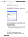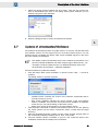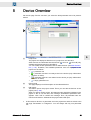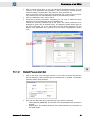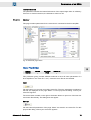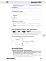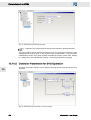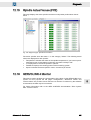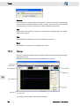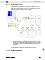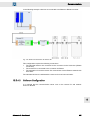
1
SIEB & MEYER
drivemaster2
User Manual
Valid for version 1.15
P-TD-0000017.5
2015-07-07
W
W
Copyright
Translation of the original instructions, Copyright © 2015 SIEB & MEYER AG
All rights reserved.
This manual or extracts thereof may only be copied with the explicit authorization of
SIEB & MEYER AG.
Trademarks
All product, font and company names mentioned in this manual may be trademarks or registered
trademarks of their respective companies.
SIEB & MEYER worldwide
For questions regarding our products and technical problems please contact us.
SIEB & MEYER AG
Auf dem Schmaarkamp 21
21339 Lüneburg
Germany
Phone: +49 4131 203 0
Fax: +49 4131 203 2000
[email protected]
http://www.sieb-meyer.de
SIEB & MEYER Asia Co. Ltd.
4 Fl, No. 532, Sec. 1
Min-Sheng N. Road
Kwei-Shan Hsiang
333 Tao-Yuan Hsien
Taiwan
Phone: +886 3 311 5560
Fax: +886 3 322 1224
[email protected]
http://www.sieb-meyer.com
2
SIEB & MEYER Shenzhen Trading Co. Ltd.
Room 306, 3rd Floor, Building A1,
Dongjiaotou Industrial Area, Houhai Dadao,
Shekou, Nanshan District,
Shenzhen City, 518067
China
Phone: +86 755 2681 1417 / +86 755 2681 2487
Fax: +86 755 2681 2967
[email protected]
http://www.sieb-meyer.cn
SIEB & MEYER USA
3975 Port Union Road
Fairfield, OH 45014
USA
Phone: +1 513 563 0860
Fax: +1 513 563 7576
[email protected]
http://www.sieb-meyer.com
drivemaster2 - User Manual
W
Chapter Overview
About this Manual
1
General Information
2
Installation
3
Device Connection to PC
4
Description of the User Interface
5
Password Protection and User Rights
6
First Steps
7
Device Overview
8
Parameters of a PS2
9
Parameters of an SD2x
10
Parameters of an FC2
11
Diagnosis
12
Tools
13
Working with Projects
14
Communication
15
Appendix
16
Index: Parameters
17
Index
18
drivemaster2 - User Manual
3
Chapter Overview
4
W
drivemaster2 - User Manual
W
Content
1
About this Manual ........................................................... 13
1.1
1.2
1.3
Illustration of Warnings ............................................................................. 13
Illustration of General Notices ................................................................... 14
Abbreviations ............................................................................................ 14
2
General Information ........................................................ 15
2.1
drivemaster2 Applications ........................................................................ 15
3
Installation ....................................................................... 17
3.1
3.2
3.3
3.4
PC Hardware Requirements .....................................................................
Install drivemaster2 ...................................................................................
Uninstall drivemaster2 ..............................................................................
USB Driver Installation ..............................................................................
4
Device Connection to PC ................................................ 23
4.1
4.2
4.3
4.4
4.5
4.6
Connection of PS2 and SD2 .....................................................................
Connection of Double-axis Compact Device SD2 ....................................
Connection of SD2B .................................................................................
Connection SD2S .....................................................................................
Connection of SD2T ..................................................................................
Connection FC2 ........................................................................................
5
Description of the User Interface ..................................... 29
5.1
5.2
5.3
General Operating Instructions for drivemaster2 ...................................... 29
Screen Layout ........................................................................................... 29
Menu Description ...................................................................................... 30
5.4
5.5
Program Start ............................................................................................ 33
Online / Offline Mode ................................................................................ 34
5.6
5.7
Download New System Software .............................................................. 38
Update of drivemaster2 Software ............................................................. 39
6
Password Protection and User Rights ............................ 41
6.1
6.2
User Levels ............................................................................................... 41
Switch User Level ..................................................................................... 42
3.4.1
3.4.1.1
3.4.1.2
5.3.1
5.3.2
5.3.3
5.3.4
5.3.5
5.3.6
5.5.1
5.5.1.1
5.5.1.2
5.5.1.3
5.5.1.4
5.5.2
5.5.2.1
17
17
18
18
USB Driver – Troubleshooting ............................................................................... 20
LibUSB Device Not Detected ................................................................................ 20
Wrong USB Driver Loaded .................................................................................... 20
23
24
25
26
26
27
Menu "Project" ...................................................................................................... 31
Menu "Edit" ........................................................................................................... 31
Menu "Loader" ...................................................................................................... 32
Menu "Settings" ..................................................................................................... 32
Menu "Extras" ....................................................................................................... 32
Menu "Help" .......................................................................................................... 33
The Online Mode ................................................................................................... 35
Searching for Connected Devices ......................................................................... 35
Online Monitoring .................................................................................................. 35
Changing a Parameter Set .................................................................................... 36
Switching into the Offline Mode ............................................................................. 37
The Offline Mode ................................................................................................... 37
Switching to the Online Mode ............................................................................... 37
drivemaster2 - User Manual
5
Content
W
6.3
Assigning User Rights ............................................................................... 42
7
First Steps ....................................................................... 45
7.1
7.2
Creating an Online Project ........................................................................ 45
Creating a Parameter Set of a Drive ......................................................... 46
7.3
7.4
Positioning via Setup Tool ........................................................................ 52
Analyzing a Drive via the Diagnosis Pages .............................................. 54
8
Device Overview ............................................................. 55
9
Parameters of a PS2 ....................................................... 57
10
Parameters of an SD2x ................................................... 61
7.2.1
7.2.2
7.2.3
10.1
Power (PS2) ........................................................................................................................
Parameter set (PS2) ............................................................................................................
Power supply (PS2) .............................................................................................................
Ballast Resistor (PS2) ..........................................................................................................
DC link capacity (PS2) .........................................................................................................
Switching-off Temperature (PS2) ........................................................................................
57
58
58
59
59
59
Multi Parameters ....................................................................................... 62
62
63
64
65
10.1.1
10.1.2
10.1.3
10.1.3.1
Create Several Parameter Sets for One Device ...................................................
Select Parameter Set ............................................................................................
Switching the parameter set in the drive ...............................................................
Parameter Set Change via the Digital Inputs ........................................................
10.2
Configuration ............................................................................................. 65
10.2.1
10.2.2
10.2.3
10.2.4
10.2.4.1
10.2.5
6
Selecting a drive .................................................................................................... 47
Creating a parameter set ...................................................................................... 47
Download of Parameter Set .................................................................................. 51
Drive ...................................................................................................................... 66
Drive Selection (SD2x) ........................................................................................................
Drive Function (SD2x) .........................................................................................................
Identification (SD2x) ............................................................................................................
Parameter set (SD2x) ..........................................................................................................
66
67
67
68
Mains (SD2x) .......................................................................................................................
Power (SD2x) ......................................................................................................................
Chopper (SD2x) ...................................................................................................................
External Ballast Resistor (SD2x) .........................................................................................
Internal Ballast Resistor (SD2x) ...........................................................................................
69
69
70
70
71
Currents (SD2x) ...................................................................................................................
DC Link (SD2x) ....................................................................................................................
Operating Frequency (SD2x) ...............................................................................................
Shutdown Temperatures (SD2x) .........................................................................................
Choke (SD2x) ......................................................................................................................
72
73
73
74
74
Power supply unit .................................................................................................. 68
Power Output Stage .............................................................................................. 72
Motor ..................................................................................................................... 75
Motor File (SD2x) ................................................................................................................. 75
Motor Type (SD2x) .............................................................................................................. 76
Motor Parameters ................................................................................................. 76
Motor Parameters for Rotary Synchronous and Voice Coil Motors (SD2x) .........................
Motor Parameters for Linear Synchronous and Voice Coil Motors (SD2x) .........................
Motor Parameters for Rotary Asynchronous Motors (SD2x) ...............................................
Variable Rated Current ........................................................................................................
76
78
79
81
Motor Measurement System (SD2x) ...................................................................................
Hall Sensor (SD2x) ..............................................................................................................
Pulse Generator (SD2x) ......................................................................................................
Incremental Encoder TTL / 12 V (SD2x) ..............................................................................
82
84
85
85
Motor measuring system ....................................................................................... 82
drivemaster2 - User Manual
W
Content
Commutation Controller (SD2x) ...........................................................................................
Linear Hall (SD2x) ...............................................................................................................
Resolver (SD2x) ..................................................................................................................
Magnetic Alignment Current (SD2x) ....................................................................................
SineCosine Encoder (SD2x) ................................................................................................
Tachometer (SD2x) .............................................................................................................
Angle Controller (SD2x) .......................................................................................................
86
86
86
87
87
88
89
10.2.6
Drive Control ......................................................................................................... 90
10.2.7
10.2.7.1
Bus System ........................................................................................................... 93
CAN Bus ............................................................................................................... 93
10.2.7.2
DNC 8 Byte Telegram ........................................................................................... 96
10.2.8
10.2.9
User Level Rights .................................................................................................. 98
Units ...................................................................................................................... 99
10.3
Monitorings ............................................................................................. 100
10.3.1
Operating Mode of the Drive (SD2x) ................................................................................... 90
Drive control (SD2x) ............................................................................................................ 91
Behavior in Case of (SD2x) ................................................................................................. 92
CAN (SD2x) ......................................................................................................................... 94
PDO 0 / PDO 1 (SD2x, CAN Bus) ....................................................................................... 95
DNC (SD2x) ......................................................................................................................... 97
PDO 0 / PDO 1 (SD2x, DNC) .............................................................................................. 97
Units (SD2x) ........................................................................................................................ 99
Position Factor (SD2x) ....................................................................................................... 100
Messages ............................................................................................................ 101
Message M12 - 'Speed zero' (SD2x) ................................................................................. 101
Message 10 - 'Ref. value reached' (SD2x) ........................................................................ 102
Message 10 - 'Position reached' (SD2x) ............................................................................ 102
10.3.2
Warnings ............................................................................................................. 103
10.3.3
Error .................................................................................................................... 109
10.4
Analog Signals ........................................................................................ 112
10.4.2
Analog Outputs ................................................................................................... 114
10.5
Digital Signals ......................................................................................... 115
10.4.1
10.5.1
Warnings Power Output Stage (SD2x) .............................................................................. 103
Warnings Motor (SD2x) ..................................................................................................... 104
W24 – Warning threshold ’current' (SD2x) ......................................................................... 104
W26 – Warning threshold ’overload current' (SD2x) .......................................................... 107
Different Warnings (SD2x) ................................................................................................. 108
Error E31 - 'Speed error/Slip' (SD2x) .................................................................................
Error E38 - 'Overspeed' (SD2x) .........................................................................................
Error E39 - 'Tracking error' (SD2x) ....................................................................................
Error E44 - 'Commutation lost' (SD2x) ...............................................................................
109
110
110
111
Analog Inputs ...................................................................................................... 112
Analog In (SD2x) ............................................................................................................... 113
Analog Out (SD2x) ............................................................................................................. 114
Digital Inputs ....................................................................................................... 116
Digital In (SD2x) ................................................................................................................. 116
10.5.2
Digital Outputs ..................................................................................................... 117
10.6
Motor Potentiometer ............................................................................... 118
10.7
Target Values .......................................................................................... 121
10.8
Encoder Emulation .................................................................................. 123
10.9
Electronic Gear ....................................................................................... 126
Digital Out (SD2x) .............................................................................................................. 117
Motor Potentiometer Setup ................................................................................................ 118
Motor Potentiometer Parameters – MOP Time Controlled ................................................ 119
Motor Potentiometer Parameters – MOP Edge Controlled ................................................ 120
Internal Target Values (SD2x) ........................................................................................... 122
Function Encoder Emulation (SD2x) .................................................................................
Encoder Emulation Motor Measuring System, AB Quadrature Signals (SD2x) ................
Encoder Emulation Speed Pulse (SD2x) ...........................................................................
Encoder Emulation Trigger Signals (SD2x) .......................................................................
drivemaster2 - User Manual
123
124
125
125
7
Content
W
Electronic Gear (SD2x) ...................................................................................................... 127
10.10
10.10.1
Controller Parameters for SERVO / VECTOR Operation ................................... 128
10.10.2
Controller Parameters for SVC Operation ........................................................... 136
10.10.3
Controller Parameters for HSBLOCK / FPAM Operation .................................... 148
10.10.4
Controller Parameters for HSPWM Operation .................................................... 159
10.10.5
Controller Parameters for HSPAM / VF Operation .............................................. 171
11
Parameters of an FC2 ................................................... 185
11.1
8
Controller ................................................................................................ 127
Current Feed Forward (SD2x, SERVO / VECTOR) ...........................................................
Current Reference Filter (SD2x, SERVO / VECTOR) .......................................................
Current Controller (SD2x, SERVO / VECTOR) .................................................................
Speed Controller (SD2x, SERVO / VECTOR) ...................................................................
Position Controller (SD2x, SERVO / VECTOR) .................................................................
Winding Detection (SD2x, SERVO / VECTOR) .................................................................
128
130
131
132
133
135
Speed Reference Values (SD2x, SVC) .............................................................................
Variable Ramps (SD2x, SVC) ............................................................................................
Speed Controller (SD2x, SVC) ..........................................................................................
Current Reference Filter (SD2x, SVC) ...............................................................................
Current Controller (SD2x, SVC) .........................................................................................
Start-up (SD2x, SVC) ........................................................................................................
Winding Detection (SD2x, SVC) ........................................................................................
137
140
141
142
143
144
146
Speed Reference Values (SD2x, HSBLOCK / FPAM) ......................................................
Variable Ramps (SD2x, HSBLOCK / FPAM) .....................................................................
Speed Controller (SD2x, HSBLOCK / FPAM) ...................................................................
Current Reference Filter (SD2x, HSBLOCK / FPAM) ........................................................
Current Controller (SD2x, HSBLOCK / FPAM) ..................................................................
Start-up (SD2x, HSBLOCK / FPAM) ..................................................................................
Winding Detection (SD2x, HSBLOCK / FPAM) .................................................................
148
152
153
154
156
157
158
Speed Reference Values (SD2x, HSPWM) .......................................................................
Variable Ramps (SD2x, HSPWM) .....................................................................................
Speed Controller (SD2x, HSPWM) ....................................................................................
Current Controller (SD2x, HSPWM) ..................................................................................
Flux Controller (SD2x, HSPWM) .......................................................................................
Flux Reference Value (SD2x, HSPWM) ............................................................................
Compensation (SD2xHSPWM) ..........................................................................................
Vibration Absorption (SD2x, HSPWM) ..............................................................................
Winding Detection (SD2x, HSPWM) ..................................................................................
159
163
164
166
167
168
169
169
170
Speed Reference Values (SD2x, HSPAM / VF) ................................................................
Variable Ramps (SD2x, HSPAM / VF) ...............................................................................
Current Controller (SD2x, HSPAM / VF) ............................................................................
V/f Characteristic Curve (SD2xHSPAM / VF) ....................................................................
Speed Controller (SD2x, HSPAM / VF) .............................................................................
Compensation (SD2xHSPAM / VF) ...................................................................................
Winding Detection (SD2x, HSPAM / VF) ...........................................................................
172
175
177
179
180
181
182
Configuration ........................................................................................... 185
11.1.1
Drive .................................................................................................................... 186
11.1.2
Power supply unit ................................................................................................ 188
11.1.3
Power Output Stage ............................................................................................ 190
11.1.4
Drive Control ....................................................................................................... 192
Drive Selection (FC2) ........................................................................................................
Drive Function (FC2) .........................................................................................................
Identification (FC2) ............................................................................................................
Parameter Set (FC2) .........................................................................................................
186
187
187
187
Mains (FC2) ....................................................................................................................... 188
Power (FC2) ...................................................................................................................... 189
Internal Ballast Resistor (FC2) ........................................................................................... 189
Currents (FC2) ...................................................................................................................
DC Link (FC2) ....................................................................................................................
Shutdown Temperatures (FC2) .........................................................................................
Choke (FC2) ......................................................................................................................
190
191
191
192
Operating Mode of the Drive (FC2) ................................................................................... 192
drivemaster2 - User Manual
W
Content
Control (FC2) ..................................................................................................................... 192
Behavior in Case of (FC2) ................................................................................................. 193
11.2
Analog Signals ........................................................................................ 194
11.2.2
Analog Outputs ................................................................................................... 196
11.3
Digital Signals ......................................................................................... 197
11.3.2
Digital Outputs ..................................................................................................... 198
11.4
Motor Configuration 1 /2 ......................................................................... 198
11.2.1
11.3.1
11.4.1
Analog Inputs ...................................................................................................... 194
Analog In (FC2) ................................................................................................................. 195
Analog Out (FC2) ............................................................................................................... 196
Digital Inputs ....................................................................................................... 197
Digital In (FC2) ................................................................................................................... 198
Digital Out (FC2) ................................................................................................................ 198
Motor Parameters ............................................................................................... 199
Motor File (FC2) ................................................................................................................. 199
Motor Type (FC2) .............................................................................................................. 200
Motor Parameters for Rotary Asynchronous Motors (FC2) ............................................... 200
11.4.2
Motor Measurement System ............................................................................... 201
11.4.3
V/f Characteristic Curve ...................................................................................... 203
11.4.4
Messages ............................................................................................................ 204
11.4.5
Holding Function ................................................................................................. 206
11.4.6
Speed Reference Values .................................................................................... 208
11.4.7
Compensation ..................................................................................................... 211
12
Diagnosis ...................................................................... 213
12.1
12.2
12.3
12.4
12.5
12.6
12.7
12.8
12.9
12.10
12.11
12.12
12.13
12.14
12.15
12.16
Actual Values (PS2) ................................................................................
Drive Actual Values (SD2x) ....................................................................
Drive Actual Values (FC2) ......................................................................
Errors and Warnings ...............................................................................
Error Memory ..........................................................................................
Position Measurement Systems .............................................................
Inputs / Outputs (PS2) ............................................................................
Digital Inputs ...........................................................................................
Digital Outputs ........................................................................................
Sine-Cosine Display ................................................................................
Delta Z Measurement .............................................................................
Analog Inputs ..........................................................................................
Analog Outputs .......................................................................................
Spindle Select (FC2) ...............................................................................
Spindle Actual Values (FC2) ...................................................................
SERVOLINK 4 Monitor ...........................................................................
12.16.1
12.16.2
12.16.3
Motor Measurement System (FC2) ................................................................................... 202
Pulse Generator (FC2) ...................................................................................................... 202
Error E31 - 'Speed error/Slip' (FC2) ................................................................................... 203
V/f Characteristic Curve (FC2) ........................................................................................... 204
Message Load Limit (FC2) ................................................................................................ 204
Message Reference Value (FC2) ...................................................................................... 205
Message Temperature Monitoring (FC2) ........................................................................... 205
Holding Function (FC2) ...................................................................................................... 206
Speed Reference Values (FC2, ) ....................................................................................... 208
Compensation (FC2) ......................................................................................................... 211
214
215
216
217
218
219
220
221
222
223
223
224
225
226
227
227
Configuration ....................................................................................................... 228
Reference values ................................................................................................ 229
Actual Values ...................................................................................................... 230
drivemaster2 - User Manual
9
Content
12.17
12.18
12.19
12.20
12.21
CAN Bus Monitor ....................................................................................
DNC Bus Monitor ....................................................................................
Object Browser .......................................................................................
Type Plate (PS2) .....................................................................................
Version Information .................................................................................
13
Tools ............................................................................. 239
13.1
13.1.1
13.1.2
13.1.3
13.1.4
13.1.5
13.2
13.3
230
231
232
235
236
drive-setup-tool ...................................................................................... 239
Menu Description ................................................................................................ 240
Status Display ..................................................................................................... 240
Actual Values and Parameters ............................................................................ 240
Function .............................................................................................................. 243
Action .................................................................................................................. 245
hiper-endat-tool ...................................................................................... 246
converter-setup-tool ............................................................................... 248
13.3.1
13.3.2
13.3.3
13.3.4
13.3.5
13.3.6
Menu Description ................................................................................................ 248
Status Display ..................................................................................................... 249
Motor Selection ................................................................................................... 249
Actual Values ...................................................................................................... 250
Reference values ................................................................................................ 250
Control ................................................................................................................. 251
13.4
Oscar ...................................................................................................... 252
13.4.1
13.4.1.1
13.4.1.2
13.4.1.3
13.4.1.4
13.4.2
13.4.3
13.4.4
13.4.5
13.4.6
13.4.7
Menu Description ................................................................................................ 253
Menu "File" .......................................................................................................... 253
Menu "View" ........................................................................................................ 254
Menu "Communication" ....................................................................................... 255
Menu "Help" ........................................................................................................ 255
Curve Selection ................................................................................................... 255
Cursor ................................................................................................................. 256
Trigger "Parameter" ............................................................................................ 257
Start / Stop .......................................................................................................... 258
Curve Display ...................................................................................................... 258
Status Bar ........................................................................................................... 258
13.5
SDx Datalogger ....................................................................................... 259
14
Working with Projects .................................................... 261
14.1
14.2
14.3
14.4
14.5
Project Files and Project Paths ...............................................................
Saving a Project ......................................................................................
Reading a Project ...................................................................................
Writing a Project ......................................................................................
Creating a New Project ...........................................................................
15
Communication ............................................................. 269
15.1
Applications and Server .......................................................................... 269
14.5.1
14.5.1.1
14.5.1.2
15.1.1
15.1.1.1
15.1.1.2
15.1.1.3
15.1.2
10
W
261
263
263
263
264
Project Wizard ..................................................................................................... 264
Select Project ...................................................................................................... 264
Edit Devices ........................................................................................................ 265
USB Communication Server ............................................................................... 270
Main Window ....................................................................................................... 270
Menu Description ................................................................................................ 271
Diagnosis ............................................................................................................ 272
Serial Communication Server ............................................................................. 273
drivemaster2 - User Manual
W
Content
15.1.2.1
15.1.2.2
15.1.2.3
Main Window ....................................................................................................... 273
Menu Description ................................................................................................ 274
Diagnosis ............................................................................................................ 275
15.2
15.3
Addressing the Devices .......................................................................... 276
Communication with a Local PC via USB ............................................... 277
15.4
Communication with a Local PC via RS232/RS485 ............................... 280
15.5
Network Communication via Remote PC ................................................ 283
15.3.1
15.3.2
15.4.1
15.4.2
Hardware Configuration ...................................................................................... 277
Software Configuration ........................................................................................ 279
Hardware Configuration ...................................................................................... 280
Software Configuration ........................................................................................ 282
15.5.1
15.5.1.1
15.5.1.2
15.5.2
15.5.3
15.5.3.1
15.5.3.2
15.5.4
15.5.4.1
15.5.4.2
Preparation of the Remote PC for Network Operation ........................................ 283
Allow Network Access ......................................................................................... 283
Start the Communication Server ......................................................................... 284
Preparation of the Application PC for Network Operation ................................... 284
Communication with a Remote PC via USB ....................................................... 284
Hardware Configuration ...................................................................................... 285
Software Configuration ........................................................................................ 285
Communication with a Remote PC via RS232/RS485 ........................................ 286
Hardware Configuration ...................................................................................... 286
Software Configuration ........................................................................................ 287
16
Appendix ....................................................................... 289
16.A
Troubleshooting ...................................................................................... 289
16.A.1
16.A.2
Installation and Security Programs ..................................................................... 289
Using the Software with Restricted Rights .......................................................... 289
16.B
FAQ ......................................................................................................... 293
17
Index: Parameters ......................................................... 295
18
Index ............................................................................. 299
drivemaster2 - User Manual
11
Content
12
W
drivemaster2 - User Manual
W
1
About this Manual
About this Manual
This chapter explains symbols, signal words and abbreviations possibly used in this
manual.
1.1
Illustration of Warnings
Depending on their degree of risk, warnings are classified into different levels. In the
manual, the different levels and types of dangers are represented as follows:
[1]
Risk level (signal word/warning color)
Classification of the risk
[2]
Safety symbol
Risk of injury
[3]
Risk symbol
Graphic representation of the source of risk
Risk levels
Risk Level
Description
Indicates an imminently hazardous situation which, if not avoided, will
result in death or serious injury.
Indicates a potentially hazardous situation which, if not avoided, could
result in death or serious injury.
Indicates a potentially hazardous situation which, if not avoided, may result
in minor or moderate injury or property damage.
Indicates a hazardous situation which, if not avoided, may result in property
damage.
Risk symbols
Risk symbol
Description
General hazardous situation
Risk of injury due to electric shock
Risk of injury due to hot surfaces
drivemaster2 - User Manual
13
1
W
About this Manual
Risk symbol
Description
1
Potentially risk of injury when working on machines with open covers/
doors
Risk of injury due to flying objects
Destruction risk of electrostatically sensitive components
Risk of property damage
1.2
Illustration of General Notices
Symbol
Description
Hint with additional, further information
Tip with suggestions and useful information
Terms and Definitions
Terms that are specifically explained in the manual are highlighted as underlined and
green words.
All term definitions are to find in the glossary of the manual. In the PDF file a mouse
click on a highlighted term jumps directly to the according definition.
1.3
14
Abbreviations
FPAM
flux pulse amplitude modulation
HSBLOCK
high-speed block commutation
HSPAM
high-speed pulse amplitude modulation
HSPWM
high-speed pulse width modulation
n.c.
not connected
SERVO
servo control
STO
safety function: Safe Torque Off
SVC
sensorless vector control
VCC
voltage at the common collector
VECTOR
vector control
VF
V/f Characteristic Curve
drivemaster2 - User Manual
W
2
General Information
General Information
This manual describes version 1.15 of the software drivemaster2.
This manual will give you basic knowledge of the functions and how to use the opera‐
ting software drivemaster2 with a SIEB & MEYER drive. You find a list comprising all
drives compatible to the software in section 2.1 "drivemaster2 Applications", p. 15.
The software allows to enter and change the performance parameters of the device in
a systematical and clear way. In addition the functions for error diagnosis and applica‐
tion are described. Any made settings have an immediate effect on the operation of the
drive. Besides the software provides different tools, which will help you to put the drive
into operation, set its parameters and analyze its performance. Further information on
the hardware of the individual drive is to find in the technical manual for this drive.
Read the hardware documentation of your device and pay attention to the
safety instructions.
2.1
drivemaster2 Applications
You can configure the following devices using the software drivemaster2:
Device type
Device
Device designation
Drive amplifier SD2x
SD2
036 21 1x / 036 21 3x / 036 98 xx
SD2B
036 21 7x
SD2S
036 21 4x / 036 21 2x
SD2T
036 21 6x
Power supply unit
PS2
036 21 9x
Frequency converter
FC2
021 90 xx
drivemaster2 - User Manual
15
2
General Information
W
2
16
drivemaster2 - User Manual
W
3
Installation
Installation
This chapter contains the following information:
▶ list with the hardware requirements to be met by the PC
▶ information on how to install and uninstall the software drivemaster2
▶ information on how to install the USB driver
Install the software drivemaster2 before connecting a device to the PC.
3.1
3
PC Hardware Requirements
The PC hardware to which the software will be installed must meet the following
requirements:
3.2
Processor
Pentium 3 or higher, 1 GHz
Operating system
Windows XP, Windows Vista, Windows 7 (32/64 bit), Windows 8
(32/64 bit)
Graphics card
Windows compatible, SVGA resolution, Color
Drive
CD drive
Hard disc
free memory size at least 500 Mbyte
Main storage
at least 1 GByte
Interfaces
a free serial interface (COM) or a USB port
Install drivemaster2
If there are any applications from the software package drivemaster2
installed on the PC, you must close these before starting the installation.
These are the applications drivemaster2, communication server, drive-setuptool, converter-setup-tool, hiper-endat-tool, SDx Datalogger and Oscar.
You need administrator rights to install the software.
Take the following steps to install drivemaster2:
➮
➮
➮
Installation from CD-ROM: Insert the CD-ROM with the software drivemaster2 in
the CD-ROM drive of your computer. Change to the CD-ROM drive and open the
folder PCSOFTWARE.
Installation from Internet: Download the latest version of the software drivemaster2
from the Internet. This is located in the download directory of the SIEB & MEYER
web page under www.sieb-meyer.de. (Please use the guest login.)
Start the installation:
─ Windows 2000/XP/Vista: Double-click on the executable file drive‐
master2_V_x_x_xxx.exe.
─ Windows 7: Right-click on the executable file drivemaster2_V_x_x_xxx.exe
and select the item "Run as administrator".
Choose a destination directory (folder).
drivemaster2 - User Manual
17
W
Installation
In Windows 7 you should not select the default path C:\Programs because
this can cause problems with user rights.
➮
✔
3
3.3
Click on the button "Install" to start the installation.
When the installation was successful, the installation program has created the
program group SIEB & MEYER AG in the start menu.
Uninstall drivemaster2
Before uninstalling the software close all applications from the software
package drivemaster2.
Proceed as follows to uninstall the software drivemaster2:
➮ In the start menu of your PC select "Programs ÿ SIEB & MEYER AG ÿ drive‐
master2".
➮ Click on the entry "Uninstall drivemaster2" to start the uninstall wizard.
➮ Follow the steps in the wizard until the uninstall process is finished.
Additional files that have been saved after installation in the directories of the
software are also deleted by the uninstall program, i.e. these files become
lost. If additional files have been saved in a newly created directory in the
installation path, these files will not be removed by the uninstall program. If
necessary, these files must be deleted manually.
3.4
USB Driver Installation
The USB driver is automatically copied when the Windows software is installed. The
installation of the USB driver is automatically started by the Windows operating system
as soon as a device is connected to a USB port of the computer.
You need administrator rights to install the USB driver.
18
drivemaster2 - User Manual
W
Installation
The following dialog window appears when you connect the device to the USB port:
3
Fig. 1: Dialog window "Found New Hardware Wizard"
➮
Select the option "No, not this time", because a connection with the Windows
Update server is not necessary for the installation. Click "Next" to confirm.
Then the USB hardware will be detected. USB>RS232/485 Converter 050201 is
detected with the name "LibUsb-Win32 SM2 TUSB1340 FirmwareLoader" and
installed.
Fig. 2: Dialog window "Found New Hardware Wizard"
➮
➮
Select "Install the software automatically (Recommended)" and click "Next". The
driver is now installed.
Click "Finish" to finish the installation.
The installation process must be repeated for every USB port. Besides, the
driver must be installed again, if you modify the structure of the USB tree,
e.g. by using a USB hub.
drivemaster2 - User Manual
19
W
Installation
3.4.1
USB Driver – Troubleshooting
If the USB connection to the drive can not be established, the USB driver installation
was possibly not successful. In order to check the driver installation, start Device
Manger on your PC (e.g. execute the file devmgmt.msc).
When the installation was successful, the Device Manager tool of the Windows opera‐
ting system displays the drive as LibUSB device as shown in the figure.
3
3.4.1.1
LibUSB Device Not Detected
If the drive is not indicated in Device Manager as shown in the figure above but
appears by means of a question mark under the item "Other devices", it has not been
detected properly. This can occur when the device has been connected to the PC
before the software drivemaster2 was installed on it for the first time. Proceed as
described in the following:
➮ Check the driver installation by disconnecting the USB connector from the PC for
a few seconds. Then reconnect the USB connector. Now, the PC repeats the USB
driver installation.
If the drive ist still not displayed correctly in Device Manager, take the following
steps.
➮ Right-click on the question mark under "Other Devices" in the Device Manager
and select "Uninstall".
➮ Then right-click on "Other Devices" and select "Scan for hardware changes". Now,
the USB driver is installed again. Proceed as described in section 3.4 "USB Driver
Installation", p. 18.
3.4.1.2
Wrong USB Driver Loaded
If there is more than one USB driver installed on the PC, Windows might not detect the
drive and another USB driver is loaded.
Symptoms of the problem:
▶ the drive is properly connected to the PC/laptop via USB (display must be on).
▶
The USB driver displayed in the taskbar on the bottom right indicates 0 ( ).
Change the driver for the drive as follows:
➮ Connect the drive via USB to the PC.
➮ Search for the loaded driver in Device Manager. The driver appears the moment
the USB cable is connected.
➮ Right-click on the 'wrong' driver and select "Update driver software..." in the
context menu.
20
drivemaster2 - User Manual
W
Installation
➮
The following dialog appears. Click on the button "Browse my computer for driver
software".
3
➮
In the following dialog window click on the button "Let me pick from a list of device
drivers on my computer".
➮
Select "LibUsb-Win32 SM2 TUSB1340 FirmwareLoader" in the following dialog
window and click "Next".
drivemaster2 - User Manual
21
W
Installation
At this point error messages may appear but you can ignore these.
3
➮
22
Restart the drive now. For that purpose you can simply unplug the USB connector
for a few seconds. The USB driver should be loaded properly now.
drivemaster2 - User Manual
W
4
Device Connection to PC
Device Connection to PC
The following instructions describe how to connect the different devices to the PC, on
which the software drivemaster2 is installed.
Further information on serial and USB communication as well as the connec‐
tion and addressing of several devices is to find in chapter 15 "Communica‐
tion", p. 269.
4.1
Connection of PS2 and SD2
4
Fig. 3: Possible connections between PC, PS2 and SD2
➮
Connect the power supply unit PS2 to the PC:
─ Via USB cable: Connect the USB cable between the female connector X13 of
the PS2 and a USB port of the PC.
─ Via USB>RS232/485 Converter 050201: Connect the SIEB & MEYER
USB>RS232/485 converter to the female connector X3 of the PS2 and to a
USB port of the PC.
─ Via RS232 to RS485 converter: Connect a commercially available RS232 to
RS485 converter to the female connector X3 of the PS2 and to the serial
interface of the PC.
The pin assignment of the RS485 cable is described in "Drive System
SD2 Hardware Description" .
➮
Connect the power supply unit PS2 (female connector X4) via a standard Ethernet
patch cable to the first drive amplifier SD2 (female connector X3).
drivemaster2 - User Manual
23
W
Device Connection to PC
4.2
Connection of Double-axis Compact Device
SD2
4
Fig. 4: Possible connections between PC and SD2 (036 21 3x)
➮
Connect the drive amplifier SD2 (036 21 3x) to the PC:
─ Via USB>RS232/485 Converter 050201: Connect the SIEB & MEYER
USB>RS232/485 converter to the female connector X3 of the SD2 and to a
USB port of the PC.
─ Via RS232 to RS485 converter: Connect a commercially available RS232 to
RS485 converter to the female connector X3 of the SD2 and to the serial
interface of the PC.
The pin assignment of the RS485 cable is described in "Drive System
SD2 Hardware Description" .
24
drivemaster2 - User Manual
W
4.3
Device Connection to PC
Connection of SD2B
4
Fig. 5: Possible connections between PC and SD2B
➮
Connect the drive amplifier SD2B to the PC:
─ Via
USB>RS232/485
Converter
050201:
Connect
the
SIEB & MEYERUSB>RS232/485 converter to the female connector X10 of
the SD2Band to a USB port of the PC.
─ Via RS232 cable: Connect the RS232 cable between the male connector X10
of the SD2B and the serial interface of the PC.
The pin assignment of the RS232 cable is described in "Drive System
SD2B – Hardware Description" .
drivemaster2 - User Manual
25
Device Connection to PC
4.4
W
Connection SD2S
4
Fig. 6: Possible connections between PC and SD2S
➮
Connect the drive amplifier SD2S to the PC:
─ Via USB cable: Connect the USB cable between the female connector X14 of
the SD2S and a USB port of the PC.
─ Via USB>RS232/485 Converter 050201: Connect the SIEB & MEYER
USB>RS232/485 converter to the female connector X19 of the SD2S and to a
USB port of the PC.
─ Via RS232 cable: Connect the RS232 cable between the male connector X19
of the SD2S and the serial interface of the PC.
The pin assignment of the RS232 cable is described in "Drive System
SD2S – Hardware Description" .
4.5
Connection of SD2T
Fig. 7: Possible connections between PC and SD2T
26
drivemaster2 - User Manual
W
Device Connection to PC
➮
4.6
Connect the drive amplifier SD2T via a USB cable to the PC. For this purpose
connect the USB cable between the female connector X14 of the SD2T and the
USB port of the PC.
Connection FC2
4
Fig. 8: Possible connections between PC and FC2
➮
Connect the frequency converter FC2 to the PC:
─ Via USB>RS232/485 Converter 050201: Connect the SIEB & MEYER
USB>RS232/485 converter to the female connector X3 of the FC2 and to a
USB port of the PC.
─ Via RS232 cable: Connect the RS232 cable between the female connector X3
of the FC2 and the serial interface of the PC.
The pin assignment of the RS232 or RS485 cable is described in the
documentation "FC2 Frequency Converter for Asynchronous Motors –
Hardware Description".
drivemaster2 - User Manual
27
Device Connection to PC
W
4
28
drivemaster2 - User Manual
W
5
Description of the User Interface
Description of the User Interface
The operation of the software drivemaster2 corresponds to the Windows conventions.
The software can be operated with the keyboard, but operation via the mouse is
easier.
5.1
General Operating Instructions for drivemaster2
The following instructions shall help you using the software.
▶ Input fields currently edited are displayed with a green background. Press the
enter key to apply your entries.
▶ When you hold the mouse pointer over an input field for a short time, the value
range is displayed.
▶ When you change a parameter, the tab "Parameters" is highlighted in yellow color.
This is reset as soon as the parameter set is saved or written into a device.
When entering floating decimal numbers, use points instead of commas.
5.2
Screen Layout
Fig. 9: Start page of the user interface
[1]
Title bar
The title bar indicates the program name, the version number and the creation
date of the software.
[2]
Menu bar
The program menu looks similar to that of common Windows programs and
provides all functions required for operating the software.
▶ User Level: Indicates the current user level (see p. 41).
drivemaster2 - User Manual
29
5
Description of the User Interface
▶
30
New version available: Opens the update dialog (see p. 39). This
button is only displayed when a new software version of drivemaster2 is
available.
[3]
Tool bar
Using the buttons here you can directly access frequently used functions of
the program menu. When you move the mouse pointer over a button of the
tool bar, a note indicating the function of this tool button is displayed for a
short time.
The field to the right of the symbols indicates the parameter set currently in
process.
[4]
Tab pages
The tab pages structure the operating functions of the software for the used
hardware thematically.
There is a directory tree in the tab page. The directory tree structures the
content of the selected tab page in nodes and sub-branches. When you select
a branch, the respective page is displayed in the display area [5].
▶ Edit project: Opens the project wizard. There you can edit the devices in
the project (see p. 265).
[5]
Display area
Here the page selected on the tab page is displayed.
[6]
Status bar
The status bar displays information on the program and project status:
▶ Project: Name of the current project
─ Online Project: The project was created with the function "Searching
for connected devices" and has not been saved under a new name
yet.
─ New project: The project was created with the function "Create a
new project" and has not been saved under a new name yet.
─ "My project name": The name of an already saved project is
displayed.
▶ Host: Name or IP address of the PC running the communication server
that is connected with the software drivemaster2
─ Here: "localhost"
▶ Server: Name of the set communication server
─ Here: "S&M USB Server".
▶ Status of communication: Device address and communication status of
the selected device
─ Communication address
Pow: Address of the power supply unit
Drv: Address of the drive
─ Communication status
Green display: Online. The software is communicating with a device.
Red display: Offline. Communicating with a device is not possible
under the selected type of communication.
Background without special coloring: offline. A project is edited filebased without device connection.
5
5.3
W
Menu Description
drivemaster2 - User Manual
W
Description of the User Interface
The program menu provides all project operations, a loader function for loading new
system software or parameter sets into the hardware, optional settings of the program
and the access to setup tools, parameter code and help.
5.3.1
Menu "Project"
▶
▶
▶
▶
▶
▶
▶
▶
▶
▶
5.3.2
Execute project wizard: Opens the project
wizard. The project wizard allows creating
a new project or editing the currently
loaded project.
Open project: A project is loaded from an
existing file (file extension *.smp).
Save project: Saves the current project
under the selected file name. If the project
has not been saved yet, the dialog "Save
project as" appears.
Save project as: Saves the current project
in a new file. Select a target directory for
the file and enter a new file name. The file
is saved with the file extension *.smp.
New parameters: Opens the parameter
wizard. The parameter wizard helps you to
create a new parameter set for the first
parameterization of a device. The param‐
eter wizard is opened only for the device
that is selected in the device overview.
Open parameters: Opens a saved param‐
eter file for the device selected in the device overview and replaces the values in
the current parameter set by the values in the parameter file.
Save parameters: Saves the current parameters of the device selected in the
device overview under the existing file name. If the parameter set has not been
saved yet, the dialog "Save parameters as" appears.
Save parameters as: Saves the current parameters of the selected device in a
new file. Select a target directory for the file and enter a new file name. The file is
saved with the file extension *.I36.
Export parameters to HTML: Creates a new HTML file with the parameter set of
the device selected in the device overview. Select a directory in which the HTML
file is to be saved and enter a file name.
Close: The program is closed.
Menu "Edit"
▶
▶
▶
▶
Cut: The marked value of a text field is cut from
the text field and stored in the clipboard. Since
open parameters are not allowed, a new value
must be entered.
Copy: The value of a text field is copied into the
clipboard.
Paste: The content of the clipboard is pasted
into an input field, provided that it is a value.
Delete: Deletes the selected part of an input
field.
drivemaster2 - User Manual
31
5
Description of the User Interface
5.3.3
Menu "Loader"
▶
▶
▶
▶
5
▶
▶
▶
▶
▶
5.3.4
Write system software to drive:
Writes a firmware file (*.X36) or a
logic file (*.L36) into the selected
drive. For further information refer to
section 5.6 "Download New System
Software", p. 38.
Write project to drives: Writes all
parameter sets of the current project
into the devices.
Write parameters to drive: Writes the
current parameter set into the
selected drive and saves it.
Read parameters from drive: Reads
the current parameter set from the
selected drive.
Write parameter sets to drive: Writes
all parameter sets created for the
selected drive into the device. This
menu item is only displayed for
devices that support the function multi parameters, p. 62.
Read parameter sets from drive: Reads all available parameter sets from the
selected drive. This menu item is only displayed for devices that support the func‐
tion multi parameters, p. 62.
Searching for connected devices: Searches for the devices connected to the PC.
Delete all parameter sets in drive: Deletes the parameters or parameter sets of the
selected drive.
Delete system software in drive: Deletes the firmware or the logic programming of
the selected drive.
Menu "Settings"
▶
▶
▶
▶
5.3.5
W
Setup connection to the device: Opens
the dialog "Setup connection to the
device" for setting the communication
server.
Language: Opens the language selec‐
tion. The languages German and
English are provided. The selected
language is immediately active.
User: Opens a dialog to log in or log out
a user and to set the user level.
Program options: Opens a dialog to
make global settings for the units. For devices of the series FC2 this dialog allows
defining the unit of the motor speed: Either as frequency in hertz or as speed in
revolutions per minute. In addition you can set the unit of the currents for all
devices here. Either they are indicated as RMS value (Arms) or as sine peak
amplitude (A).
Menu "Extras"
The menu items displayed in the menu "Extras" depend on the device selected in the
device overview. The following figure is an example of the menu "Extras" for an SD2x.
32
drivemaster2 - User Manual
W
Description of the User Interface
▶
▶
▶
▶
▶
▶
Oscar: Opens the application Oscar in a new
window. Oscar is a diagnosis tool to be used for
recording values and displaying these as curves.
drive-setup-tool: Opens the application drivesetup-tool in a new window. The drive-setup-tool
is used for initial operation of a drive amplifier or
operating a motor without higher-ranking control.
converter-setup-tool: Opens the application
converter-setup-tool in a new window. The
converter-setup-tool is used for initial operation of
a frequency converter or operating a motor
without higher-ranking control.
hiper-endat-tool: Opens the application hiper-endat-tool in a new window. The
hiper-endat-tool is used for diagnosis and parameterization of the absolute enco‐
ders Hiperface and EnDat. Using the hiper-endat-tool is only possible, when a
motor with an absolute encoder is connected.
SDx Datalogger: Opens the application SDx Datalogger in a new window. Using
the application SDx Datalogger up to four parameters can be recorded over a
longer period of time.
Parameter Code: Opens a dialog window indicating the encrypted parameter
code. A parameter code is provided for each parameter set. Via this code the
SIEB & MEYER service staff can read the according parameter set out or decode
the passwords in case of an emergency (e.g. password loss).
When one of the applications (except Parameter Code) is started, it commu‐
nicates with the device currently selected in the device overview. If another
device is selected in the device overview, the new address will not be sent to
the application. In this case the application must be closed and restarted.
5.3.6
Menu "Help"
▶
▶
▶
▶
▶
5.4
drivemaster2 - Manual: Opens the user manual for
the software drivemaster2 as PDF file.
Setup instruction: Displays the available setup
instructions for the different drive functions. These
are stored as PDF files. You can open the desired
manual with one click.
Hardware description: Displays the available hard‐
ware descriptions for the different devices. These
are stored as PDF files. You can open the desired
manual with one click.
Info: Displays version information of the software
and the contact address of SIEB & MEYER
Check for updates: Opens the dialog "Check for updates" to download an update
for the software drivemaster2 directly from the SIEB & MEYER web page. For
further information refer to section 5.7 "Update of drivemaster2 Software", p. 39.
Program Start
The software drivemaster2 is started via the Windows start menu "Programs ÿ
SIEB & MEYER AG ÿ drivemaster2". The welcome screen appears as long as the
program is initialized.
Then a dialog window appears asking the user for the first working step:
drivemaster2 - User Manual
33
5
W
Description of the User Interface
5
Fig. 10: Dialog window "Start"
The following options are available:
▶ Show initial operation guide: Provides a selection of PDF documents about the
initial operation of the individual devices. Click on the desired document to open it.
▶ Search for one connected device: Searches the address range for one address‐
able device. As soon as the device is found, it is displayed in the user interface
and a so-called online project is created.
▶ Search for all connected devices: Searches for addressable devices in the
complete address range and creates a so-called online project.
▶ Open a parameter file: Opens a parameter file of a drive that is already saved in
the file system of the PC. Then, this file can be edited offline.
▶ Load an existing project: An already existing project is loaded and can be edited in
the offline mode.
▶ Create a new project: Creates a new project by means of the project wizard that
can be edited in the offline mode.
▶ Setup connection to the device: Opens the dialog for setting the communication
server. "After the program installation the USB server is set as default server for
the communication."
▶ Exit the program: Closes the software drivemaster2.
5.5
Online / Offline Mode
The software drivemaster2 offers two operating modes: online and offline mode.
When the online mode is active, the software is permanently connected to the device
selected in the device overview. Changed parameter sets can be loaded directly into
the connected devices. In the online mode the tab page "Diagnosis" offers assistance
for analyzing the behavior of the device.
The offline mode, however, only works on the basis of files. The tab page "Diagnosis"
is not provided in the offline mode.
34
drivemaster2 - User Manual
W
5.5.1
Description of the User Interface
The Online Mode
The online mode is probably the most commonly used working mode for the software
drivemaster2. When the user activates the function "Searching for connected devices",
the software automatically works in the online mode.
5.5.1.1
Searching for Connected Devices
In order to work in the online mode, select the option "Searching for connected
devices" after program start. The corresponding dialog is displayed. Later you can
switch into the online mode via the menu "Loader ÿ Searching for connected
devices".
You can also click on the symbol
in the tool bar.
5
Fig. 11: Dialog window "Searching for connected devices"
When the dialog is opened, the software starts immediately to search for addressable
devices in the complete address range. The software searches for every power supply
address in the address range of the drive addresses from 0 to 31. During the search all
addressable devices are already arranged in an online project and listed in a tree-type
structure in the window "Found devices". The progress bar below indicates the
progress of the device address scan.
The following buttons can be selected:
▶ Cancel / New search: This button has two functions. A currently running search
can be canceled. Then the "Cancel" button is renamed in "New search" and the
device search can be restarted.
▶ Apply: Closes the dialog. All found devices are applied to the software and form a
new online project. A previously opened project will be overwritten.
▶ Close: Closes the dialog and the search result is not applied. The former project is
kept.
5.5.1.2
Online Monitoring
When the online mode is active the software drivemaster2 permanently monitors the
device selected in the device overview (so-called "online monitoring").
The online monitoring sets the device status in the status bar to "online" or "offline".
drivemaster2 - User Manual
35
W
Description of the User Interface
The following values are read out for instance:
▶ CRC check sum of the parameter set
▶ serial number of the device
▶ identification of the device
If one or several values are changed in the background, e.g. by a higher-ranking
control, a message appears saying that the parameter set does not match the param‐
eter set in the device. In this case the parameter set from the device will be uploaded
automatically.
This function has been implemented to ensure that during online operation the param‐
eter set in the software is identical to the parameter set in the device.
5.5.1.3
Changing a Parameter Set
Parameters can also be modified during online operation. Any modification of parame‐
ters in the software must be sent to the device via the menu "Loader ÿ Write parame‐
ters to drive".
5
You can also click on the symbol
in the tool bar.
If you have changed more than one parameter set for the connected device (see Multi
Parameters, p. 62), you can download all changes into the drive at once via the
menu "Loader ÿ Write parameter sets to drive".
If the modified parameter set is not transmitted to the device, the following dialog will
appear in the moment another device is selected in the device overview
Fig. 12: Dialog window "Save changes"
The following options are available:
▶ Save parameters into file: Saves modifications in the parameter set in a file. Then,
the device is changed.
▶ Download parameters into drive: Loads the changed parameter set into the corre‐
sponding drive. Then, the device is changed.
▶ Do not save changes: The changes are not saved and not written into the device.
They remain, however, in the user interface. Then, the device is changed.
If the user selects another device in the device overview, whose parameter set has
been modified in the software but not saved, the software will detect inconsistencies
with the online device.
36
drivemaster2 - User Manual
W
Description of the User Interface
The following dialog appears:
5
Fig. 13: Dialog window "Upload new parameters?"
The following options are available:
▶ Save changes: The changes are saved in a job list. Then, the parameter set is
loaded from the target device and applied to the user interface.
▶ Do not save changes: The changes are not saved. Then, the parameter set is
loaded from the target device and applied to the user interface.
▶ Cancel: The changes are not saved, but remain in the user interface of the target
device. The parameter set is not read from the target device.
5.5.1.4
Switching into the Offline Mode
When you have finished all changes in the parameter sets of the project currently
loaded in the drivemaster2 software, you can switch into the offline mode for safety
reasons.
By click on the offline symbol
the software switches into the offline mode. Conse‐
quently the online monitoring and the diagnosis pages are deactivated.
5.5.2
The Offline Mode
In the offline mode you can create a project without device connection and prepare it
for later use as online project.
To check or compare parameter sets an already existing project can be opened. This
way the user can access all devices and parameters, whereas it does not matter
whether the system is connected to a machine.
The software drivemaster2 works automatically in the offline mode when a project is
created or opened after the program was started. This status is displayed by a color‐
less display in the status bar. The online monitoring is not active in this mode. The
parameters of a single parameter set can be edited.
5.5.2.1
Switching to the Online Mode
The offline mode does not allow writing a single parameter set into a special device as
well as reading a single parameter set from a special device. The menu items in the
drivemaster2 - User Manual
37
Description of the User Interface
W
menu "Loader" are not available. The purpose of this function is to prevent that a
wrong parameter set is loaded by mistake into a correctly parameterized device.
The user must select one of the following items from the menu "Loader" or the respec‐
tive symbol in the tool bar to switch from the offline to the online mode:
▶
Write project to drives
: Loads all parameter sets of the offline project into the
devices. For this purpose the software switches into the online mode and writes
the parameter sets one after the other into the devices. Therefore it is necessary
that the structure of the offline project is identical to that of the connected devices.
▶
: Switches the software to the online mode
Searching for connected devices
and searches for all addressable devices. The previously loaded offline project is
deleted and replaced by the new online project.
5
5.6
Download New System Software
Via the software drivemaster2 you can write new device firmware and logic software
into the connected drive.
When you install the software drivemaster2, all firmware and logic files currently avail‐
able for the different drives are copied into the directory "SM_Sys" in the installation
path of the drivemaster2 software. The system software is filed according by device,
type (logic or firmware) and function.
You find the latest system software in the download directory of the SIEB & MEYER
web page under www.sieb-meyer.com. (Please use the guest login.) For assistance
refer to the software catalog ("SystemsoftwareCatalog.pdf"), which indicates the suit‐
able logic and firmware needed for a particular drive function. Save the desired firm‐
ware and/or logic file in the directory "SM_Sys" in the installation path of the software
drivemaster2.
Make sure that the device version of the device corresponds to the software
version. Otherwise an error message will be displayed when you load the
software.
The appropriate device version is indicated in the software designation as
follows:
▶ Device version: 7.000
▶ Software: f01001v07014.x36
Proceed as follows to write a new system software to the drive:
➮ Select the menu item "Loader ÿ Write system software to drive". A dialog
window for selecting the firmware or logic file is opened.
➮ Navigate to the directory "SM_Sys" in the installation path of the software drive‐
master2.
38
drivemaster2 - User Manual
W
Description of the User Interface
➮
Select the desired system software and click "Open". Then the new system soft‐
ware is downloaded to the drive. In the dialog "Write system software" you can
watch the progress of the download.
✔
When the dialog window is closed, the download is finished.
5
5.7
Update of drivemaster2 Software
The software drivemaster2 provides an update service, so the user can find and install
new software versions. For this purpose the PC must have Internet access. If a new
software version is available, the button "New version available" appears in the menu
bar of the software drivemaster2.
The update contains the standard version of the software drivemaster2. If you
have an individual installation with other company logos, addresses etc., you
can adapt or hide the update service. For detailed information refer to the
documentation "drivemaster2 – Individual Installation".
Proceed as follows to update the software:
➮ Click the button "New version available" or open the menu "Help ÿ Check for
updates".
The dialog "Check for updates" appears:
Installed version: Indicates the version of the software drivemaster2 that is
currently running on you PC.
─ New version available: Indicates the version number of the new software
version, if available. If not, the text "No newer Version available" is displayed.
In this case you can exit the dialog via the button "Close".
─ What's new: Opens the changelog for the new software version.
Click the button "Download" to save the new software version on your PC. (Moving
the mouse pointer over the button "Download" shows a tooltip with the target
directory.)
After the download the button "Install" is active. Close all other program parts of
the drivemaster2 software packages at first. Then, click "Install".
The new software version is installed on your PC now. Follow the steps in the
installation wizard until the install process is finished.
─
➮
➮
✔
drivemaster2 - User Manual
39
Description of the User Interface
W
5
40
drivemaster2 - User Manual
W
6
Password Protection and User Rights
Password Protection and User
Rights
Via password protection the OEM (machine manufacturer) can define passwords for
different user groups and assign corresponding access rights. Thus certain parameters
and functions (e.g. Write parameters to drive) can be protected against unwanted
access.
Currently password protection is not supported for devices of the series PS2
and FC2. These devices appear in the user level "User" in the menu bar.
The passwords are organized together with the parameter set of the device. They are
deposited in the data block in coded form. Thus they are known by the device and the
software drivemaster2.
Via the page "User Level Rights" on the tab page "Parameters" different passwords for
the access can be assigned. A user hierarchy with up to three user levels can be
created.
6.1
User Levels
The software provides the following three user levels:
User level
Description
Password
Admin
User with all predetermined access right
Password with max. 8 characters
OEM
User with changeable access rights
Password with max. 8 characters
User
User with changeable access rights
No password
User level after software start
After starting the software the user is logged in the currently lowest user level defined
in the parameter set.
The lowest user level depends on the password assignment:
▶ When passwords were assigned to the Admin level and the OEM level, the User
level is the lowest user level.
▶ When a password was assigned to the Admin level only, the OEM level is the
lowest user level.
▶ When no passwords were assigned, the Admin level is the lowest user level.
▶ When no device is connected to the software on startup, the user is logged in as
Admin and can create a new parameter set.
User level of a parameter set
When a new parameter set is created, the passwords are not assigned yet and the
user has administrator rights for this parameter set.
If you load a parameter set from the device, this parameter set is protected by the
passwords saved in the device. The parameter set is opened in the lowest user level.
If you load a parameter set from a file, this parameter set is protected by the pass‐
words saved in this file. The parameter set is opened in the lowest user level.
drivemaster2 - User Manual
41
6
W
Password Protection and User Rights
In order to write a parameter set to the device you must enter the password
of the Admin or the OEM level (depending on the assigned rights for param‐
eter download) before you start the download. After writing the parameter is
finished the password saved in the new parameter set is valid.
6.2
Switch User Level
In order to switch to another user level, you must log in using the password of the
according user level.
For this purpose open the dialog "Login" via the menu "Settings ÿ User ÿ Log in"
6
Fig. 14: Login dialog
➮
✔
Enter the password of the desired user level.
If the password is correct, the software switches to the according user level.
Via the menu "Settings ÿ User ÿ Log out" you can leave the current user level.
Then, the software switches to the lowest user level.
6.3
Assigning User Rights
You can assign passwords and user rights on the parameter page "User Level Rights".
When you are logged in as Admin, you can change the rights and passwords of all
users. When you are logged in as OEM, you can change the rights of the User level
and your password (if the corresponding right is assigned). For the level User this page
is write-protected.
42
drivemaster2 - User Manual
W
Password Protection and User Rights
6
Fig. 15: Parameter page "User Level Rights"
[1]
User level
Indicates the user level in which the user is currently logged in.
Via the button
you switch to the lowest user level for the parameter set.
[2]
Node: User level rights
Node on the tab page "Parameters" that must be clicked to open the page for
assigning the passwords and user rights.
[3]
Passwords
In this field you can edit the passwords for the Admin level and the OEM level.
Activate the check boxes to display the current passwords.
[4]
User Level Rights
Field in which you can assign the access rights for the lower user levels. Acti‐
vate the according check boxes to assign certain access rights to a user level.
Passwords
The passwords must be made up of at least one character and maximum eight charac‐
ters. The characters can be numbers or letters (except special characters or umlauts).
The software differentiates between capital and lower case letters.
Consider the following items when assigning passwords:
▶ The password of the OEM level can only be assigned when you have already
defined a password for the Admin level.
▶ The passwords of the OEM and the Admin levels must be different.
▶ If no password is assigned (i.e. the input field is left empty), the respective user
level is not protected by password and the user automatically attains this user
level.
▶ For devices with several parameter sets (see multi parameters, p. 62)
SIEB & MEYER recommends to use the same passwords for all parameter sets.
On delivery no passwords are assigned in the drives and in the software
drivemaster2.
drivemaster2 - User Manual
43
Password Protection and User Rights
W
6
44
drivemaster2 - User Manual
W
7
First Steps
First Steps
This chapter is a quick start description for the software drivemaster2. The description
particularly considers the operating elements for the online parameterization of a drive.
It is required that a drive is connected with the PC.
7.1
Creating an Online Project
Program start
➮
Start the software via the Windows start menu "Programs ÿ SIEB & MEYER AG"
(provided that you have saved the software in the default path).
The start screen appears.
7
Settings for the Communication
➮
Click on the button "Setup connection to the device" to open the dialog window
"Setup connection to the device".
➮
Select and configure the communication server. The selection depends on the
used device and its wiring. For detailed information refer to chapter 15 "Communi‐
cation", p. 269.
drivemaster2 - User Manual
45
W
First Steps
➮
Click on the button "Search devices + connect" to return to the dialog window
"Start".
For the following steps it is provided that the communication server is set correctly.
Searching for connected devices
7
➮
Select the menu item "Search for all connected devices" in the start screen.
➮
The found devices will be applied to the user interface by mouse click on the
button "Apply". All selected drives are combined to form the "online project".
All data required for the operation are summarized in a data structure, the
parameter set. Initial operation of a device is only possible with a complete
and correct parameter set.
7.2
Creating a Parameter Set of a Drive
A parameter set can be created manually or with the aid of a wizard. Such a wizard is
provided for each drive that can be parameterized with the software drivemaster2.
In the following example an SD2 with the drive function SERVO / VECTOR is parame‐
terized via the wizard.
For parameterization and initial operation of an SD2S the following quick start guides
are available depending on the required drive function:
46
FPAM operation:
SD2S Setup Instructions – HSBLOCK / FPAM Operation
HSPWM opera‐
tion:
SD2S Setup Instructions – HSPWM Converter
SVC operation:
SD2S Setup Instructions – Sensorless Vector Control (SVC)
V/f operation:
SD2S Setup Instructions – V/f Operation
drivemaster2 - User Manual
W
7.2.1
First Steps
Selecting a drive
➮
Open the tab page "Device overview" and select the drive you want create a
parameter for. In the figure the axis A of a drive amplifier SD2 is selected:
If the selected drive is not parameterized, the device is not displayed on the
right side of the user interface. A dialog for the creation of a parameter set
will be displayed instead. This you can create manually or with the aid of the
wizard described in the following chapter.
7.2.2
Creating a parameter set
➮
Start the wizard via the menu "Project ÿ New parameters". The wizard for
parameterizing an SD2 is started automatically. The structures of the all wizards
are similar, the only differences are drive-specific details.
The first page serves for parameterizing the basic device. Since the basic device
already exists physically, the displayed parameters are read from the drive and
can not be modified.
drivemaster2 - User Manual
47
7
W
First Steps
➮
Click "Next" to continue.
➮
Select the required drive function on the page "Base Data" and enter identifying
information for the drive. This identification takes no effect on the function of the
drive. It is only used for your administration.
Click "Next" to continue.
➮
7
➮
48
Enter the parameters of the used motor type. This can be done manually or by
loading an already existing motor file (*.mot).
When you work for the first time with the software drivemaster2, no motor file will
be available. Hence, you must enter the motor data manually. In this example a
SIEB & MEYER motor is used.
drivemaster2 - User Manual
W
First Steps
➮
Click "Next" to continue.
➮
Enter the technical data of the connected motor. All input fields must be filled with
the correct motor data, otherwise the parameterization of the motor can not be
finished correctly. The highlighted motor data (in bold) are necessary and must be
adapted to the connected motor.
Click "Next" to continue.
➮
➮
On this page you must enter the parameters of the measuring system connected
to the motor.
drivemaster2 - User Manual
49
7
W
First Steps
➮
Click "Next" to continue.
➮
On this page you can set the performance of the speed controller via its stiffness.
For this purpose the relation of the mass moments of inertia must be known.
This configuration of the controller only works, if the mass moments of inertia
are ideally coupled. Complicated mechanical elements (spring mass systems
with influence of shafts and couplings) require setting the speed controller
manually or by means of special tools!
7
➮
Click "Next" to continue.
➮
Select the operating mode and the control channel of the drive.
For initial operation we recommend to select Velocity mode 1 and drive
control via serial interface. This configuration allows positioning the motor via
the setup tool, here via drive-setup-tool.
✔
50
Now the created parameter set exists in the software drivemaster2 but it is not
downloaded to the drive yet. Writing the parameter set into the drive is done via a
download.
drivemaster2 - User Manual
W
7.2.3
First Steps
Download of Parameter Set
➮
Start the download via the menu item "Loader ÿ Write parameters to drive". In
the window "Write parameters" you can watch the progress of the download.
✔
After the window has disappeared the parameter download is finished and the
configuration of the drive is completed.
Troubleshooting: wrong system software
If the parameterization of the drive is not suitable for the logic or firmware in the drive,
the following dialog opens to point out the problem.
You have the following possibilities:
1. Cancel parameter download: The process is canceled and you can change the
parameters of the drive as required.
2. Update system software: You load the logic and firmware file that is suitable for
the parameterization into the drive. For this purpose the following dialog is
opened:
drivemaster2 - User Manual
51
7
W
First Steps
The table lists all firmware and logic files that are available in the installation path
of the software drivemaster2 for the current drive configuration. Select the desired
system software.
─ For assistance you can click the button "Show software catalog" to open a
PDF file indicating the suitable logic and firmware needed for a particular drive
function.
─ Click on the button "Select another firmware" to open the directory "SM_Sys"
in the installation path of the software drivemaster2. Here you find all firmware
and logic files that were supplied with the software installation.
Click the button "Do download" to write the selected system software to the drive.
After the download of the system software is finished, the parameter set is auto‐
matically downloaded to the drive.
7.3
Positioning via Setup Tool
In the following the drive-setup-tool is described as an example for all setup tools. The
other setup tools are operated the same way.
Calling the setup tool
➮
Start the setup tool via the menu item "Extras ÿ drive-setup-tool". The tool is an
independent program for initial operation of drives.
➮
Click on the button "Drive Setup Active". The following dialog appears.
➮
Click "OK" to confirm. Thus, the setup tool controls the drive.
7
52
drivemaster2 - User Manual
W
First Steps
Setting the parameters
For setting up a drive amplifier we recommend using the reversing function.
WARNING
Risk of injury while working with the reversing function
This function in particular needs to be handled carefully. Since the PC writes the
values cyclically into the device, the actual time values may differ pretty much from
the set time values and these may not be met. Consider the risk of injury while
standing near to the motor or other machine parts.
Keep clear from the machine while moving the axes via the setup tool.
NOTICE
Initial operation with wrong wiring or parameterization
To avoid damage of the machine due to wrong wiring or parameterization we
recommend to limit the maximum current to a small value during initial operation.
➮
Select the entry "Velocity - reversing function" from the list in the field "Function".
Positioning
The drive can start moving when the parameterization of the selected profile is
finished. Therefore, proceed as follows:
➮ Click on the button "Enable Operation" to activate the controller.
➮ Start the positioning of the drive with the set profile by mouse click on the button
"Start".
➮ Positioning the drive can be stopped at any time by a second mouse click on the
button "Start".
➮ In order to deactivate the controller click on the button "Enable Operation" once
more.
During the positioning process all relevant data is displayed in the setup tool.
drivemaster2 - User Manual
53
7
W
First Steps
7.4
Analyzing a Drive via the Diagnosis Pages
The data of the drive are also displayed on the diagnosis pages of the software drive‐
master2. The pages are available via the tab page "Diagnosis".
The page "Actual Drive Values" may be of special interest during initial operation.
7
The setup is finished, when the drive positions without error.
54
drivemaster2 - User Manual
W
8
Device Overview
Device Overview
Via the tab page "Device overview" you select the drive/parameter set to be parame‐
terized.
[1]
Project tree
The project tree displayes all devices of a project in a tree structure.
SD2x devices are subdivided into their drives: = drive A,
= drive B (only
available with double-axis drive amplifiers).
You can create several parameter sets for SD2x devices (see Multi Parame‐
ters, p. 62). Therefore, the available parameter sets are displayed in the
project tree as follows:
▶
= parameter set
▶
= parameter set that is currently active in the device (only visible when
the drive is online)
▶
= parameter set that is not written into the device yet (only visible when
the drive is online)
▶
= empty parameter set
[2]
Device page
This page displays a brief description of the selected device.
[3]
Edit project
This button opens the project wizard. There you can edit the devices of the
project (see p. 265).
When you edit an online project, all parameter sets should be initialized in the
project. If this is not the case, the message "Uninitialized parameter sets"
appears. Click "OK" to confirm the message. Thus, all parameter sets are
read from the devices. Afterwards the project wizard will open.
➮
At first select a device or a parameter set in the project tree and then switch to the
tab page "Parameters" or "Diagnosis". You can always edit only one parameter
set.
drivemaster2 - User Manual
55
8
W
Device Overview
The selection made in the "Device overview" affects the program behavior of
the software drivemaster2. That means: The selected device influences the
contents of the tab pages "Parameters" and "Diagnosis" as well as the menu
item "Extras".
The following parameter descriptions are ordered by device type.
8
56
drivemaster2 - User Manual
W
9
Parameters of a PS2
Parameters of a PS2
The power supply unit PS2 is always supplied without a valid parameter set (error
E08). Before initial operation you must set the following power supply parameters via
the software drivemaster2 and write the parameter set into the device.
All parameters of the power supply unit PS2 are combined in parameter groups and
displayed on the page "Setup".
9
[1]
Power supply unit
The root of the tree is the power supply unit selected in the "Device overview".
[2]
Parameter page
All configurations of the power supply unit PS2 are made on the parameter
page "Setup".
Power (PS2)
This parameter group provides for general information of the current power supply unit.
Device ID
Indicates the general designation (type) of the used drive electronics. If the user inter‐
face is not updated and thus can not recognize the drive, question marks '?' are
displayed instead of the drive designation.
Device name
The user can enter an individual name for the power supply unit in this field. The
maximum length of the name is 15 characters.
drivemaster2 - User Manual
57
W
Parameters of a PS2
Parameter set (PS2)
This parameter group displays general information on the parameter set that is
currently used in the power supply unit.
Creation date
This field displays date and time of the last modification of the parameter set. The crea‐
tion date is updated automatically when the parameter set is modified.
User version
The field indicates the version of the parameter set. The user can freely select this
number.
Power supply (PS2)
This parameter group serves to enter general data of the mains supply that is
connected to the power supply unit.
Mains phases
This parameter specifies the number of mains phases. The user can select between
single-phase and three-phase current via radio buttons. The parameter depends on the
provided supply system type.
For further information refer to the hardware documentation.
9
Voltage
The parameter indicates the main voltage of a sine mains supply in volts (RMS value).
▶ Single-phase operation: Voltage is related to the neutral conductor.
▶ Three-phase operation: Voltage is defined between two phases.
This parameter is used by the load monitoring. In the event of an error the power
supply unit is switched off with the errorE01 "Preloading error DC link voltage" or E02
"Overvoltage in DC link".
Mains frequency
The parameter indicates the frequency of the sine mains supply in hertz or the supply
of direct current (DC). The available variants are set by means of a list box.
Off time
The parameter indicates the switchoff time of the mains supply in the event of an error
in milli seconds.
If e.g. a mains failure occurs, the PS2 will not try to restart before the time indicated
here is passed (the power supply unit restarts with pre-loading of the intermediate
circuit).
58
drivemaster2 - User Manual
W
Parameters of a PS2
Ballast Resistor (PS2)
This parameter group provides parameters to enter the technical data of the ballast
resistor that must be connected to the power supply unit.
For the values of the ballast resistor refer to the respective data sheet of the manufac‐
turer.
Power
The parameter indicates the rated power of the used ballast resistor in watts. Refer to
the data sheet of the manufacturer for this value.
Value of resistance
The parameter indicates the nominal resistance of the resistor in ohms. Depending on
the device the resistance can be set within a preset range. If the entered value is not in
that range, the parameter is reset to the previous value.
Time for max. power
The parameter indicates the maximum period of time in seconds, in which the peak
power can be supplied continuously.
The parameters are also used for the I²t calculator of the ballast resistor. If
the power converted in the ballast resistor is too much, the I²t calculator trig‐
gers the error E04 "Ballast circuit load (Chopper I²t)".
DC link capacity (PS2)
This parameter serves to indicate possible external capacities at a power supply unit.
These result from devices or separate capacitors which are connected to the DC link.
External
The parameter indicates the additional electrical capacity in μfarads and is used for the
pre-load monitoring.
Switching-off Temperature (PS2)
This parameter group displays the limiting values of the thermal load of the power
supply unit. These are read-only values loaded from the hardware.
Heat sink
The parameter indicates the maximum heat sink temperature allowed for the operation
of the system in degree centigrade. If this temperature is exceeded, the device will be
switched off automatically and the error message E05 "Heat sink temperature too high"
appears.
Environment
The parameter indicates the maximum ambient temperature allowed for the operation
of the system in degree centigrade . If this temperature is exceeded, the device will be
switched off automatically and the error message E06 "Ambient temperature too high"
appears.
drivemaster2 - User Manual
59
9
Parameters of a PS2
W
9
60
drivemaster2 - User Manual
W
10
Parameters of an SD2x
Parameters of an SD2x
All parameters of a drive amplifier of the model range SD2x (devices: SD2, SD2B,
SD2S, SD2T) are available via the tab page "Parameters". To provide an overview of
the parameters they are combined in pages, whereas these pages are structured via
nodes and branches as final nodes (leafs) in a tree structure.
[1]
Drive
The root of the tree is the drive selected in the "Device overview". With a
double-axis device the parameterization applies only to the selected axis.
When one drive has several parameter sets, the parameter set selected in the
"Device overview" is displayed.
[2]
Thematic sub-division of the parameterization
The parameter pages are combined thematically by the subordinated nodes.
[3]
Parameter pages
Via the parameter pages you configure the drive according to the application.
The individual parameters are combined thematically in groups.
Assignment of parameters by drive function/device
The displayed parameter pages depend on the selected drive function.
At the beginning of each parameter group you find a two-rowed table explaining for
which drive function (and possibly for which device) the parameters apply:
[1]
Drive function
[2]
drivemaster2 - User Manual
parameter group is available for the drive function
61
10
W
Parameters of an SD2x
[3]
[4]
10.1
parameter group is only available with the indicated devices for the drive func‐
tion
parameter group is not available for the drive function
Multi Parameters
The function multi parameters allows assigning several parameter sets to one drive.
The parameter sets are saved in the memory of the drive.
For information on saving and managing several parameter sets in one project refer to
chapter 14 "Working with Projects", p. 261.
10.1.1
Create Several Parameter Sets for One Device
➮
Switch to the tab page "Device overview" and click on the desired drive. The page
"Summary" on the right side displays the parameter group "Parameter set".
➮
Click on the button "Add" to create a new parameter set. The following dialog
appears:
10
62
drivemaster2 - User Manual
W
Parameters of an SD2x
➮
➮
➮
10.1.2
Enter a number and a name, so you can identify the parameter set later. You can
create up to 64 parameter sets (numbers 0 – 63) for one drive. Consider that the
software creates a separate file in the project for each parameter set.
Click on the button "Add" to apply the new parameter set. In the "Device overview"
the parameter sets are subordinated to the drive and ordered by number.
Click on a parameter set in order to edit it.
Create the according parameters. Afterward you can copy or delete the entire
parameter set via the parameter group "Parameter set".
Thereby the previous parameter set is still active. The active parameter set is
displayed in green color in the device tree. The diagnosis pages always apply to
the active parameter set. If you edit another than the active parameter set, the
display of the parameter set in process (in the tool bar) is highlighted in yellow
color.
10
Select Parameter Set
➮
Click on the drive in the tree-type structure. In the online mode the field "Param‐
eter set selection" in the parameter group "Parameter set" is enabled. In the offline
mode this field is write-protected.
➮
Here you can define the way a parameter set of the device is selected.
─ Fixed selection (EEPROM): The number of the desired parameter set must be
entered.
─ Digital inputs: The desired parameter set is determined by the connection of
the digital inputs.
drivemaster2 - User Manual
63
W
Parameters of an SD2x
If you wish to select the different parameter sets via the digital inputs, the
control channel of all parameter sets must be set to "Digital inputs" (see
p. 91). Pay attention that the digital inputs of all parameter sets of the
device are parameterized identically for the parameter set selection
(Parameter set Bit x).
─
10.1.3
File bus: The desired parameter set is selected via the object
DEV_CTRL_SELECT_PARAMETER_SET (153). For further information on
using objects refer e.g. to the documentations "Drive System SD2 – DNC 8
Byte Telegram" and "Drive System SD2 – CAN Bus Connection".
Switching the parameter set in the drive
➮
➮
In order to change the active parameter set in the drive, you must switch-off the
controller first. (Switching to another parameter set is only possible, when the
controller is switched off.)
The drive reacts by removing the bit M01 "Power output stage switched on". From
that moment the parameter set can be changed.
Change the parameter set by entering the correct parameter set number or by
connecting the digital inputs accordingly (see below).
The devices in table top design of the series SD2T allow changing the parameter
set also by means of the push buttons on the device front panel (see hardware
description).
10
64
drivemaster2 - User Manual
W
10.1.3.1
Parameters of an SD2x
Parameter Set Change via the Digital Inputs
The following diagram shows the timing when the parameter set is switched via the
digital inputs. The functions of the digital inputs must be defined accordingly in the soft‐
ware drivemaster2. Switching from one parameter set to another is actually done by
unsetting and setting the control input "switch on":
Fig. 16: Timing diagram for parameter set change (via the digital inputs)
10.2
10
Configuration
The node "Configuration" provides the parameter pages "Drive", "Power output stage",
"Motor", "Motor measurement system", "Drive control" and "User level rights".
Depending on the device and certain settings the pages "Power supply", "Bus system"
and "Units" are displayed additionally.
The individual pages display all data required for the general configuration of the drive
system.
drivemaster2 - User Manual
65
W
Parameters of an SD2x
10.2.1
Drive
This parameter page serves for general configuration of the drive amplifier and
provides information on the current parameter set.
Fig. 17: Parameter page "Drive"
Drive Selection (SD2x)
10
SERVO /
VECTOR
HSPWM
HSPAM / VF
HSBLOCK /
FPAM
✔
✔
✔
✔
This field displays the characteristics of the selected power electronics of the drive
amplifier. This parameter group is write-protected.
Drive designation
The parameter indicates the general designation (type) of the used drive electronics. If
the user interface is not updated and thus can not recognize the drive, question marks
'?' are displayed instead of the drive designation.
The button "Edit project" opens the project wizard to change the device or the entire
project (see section 14.5.1.2 "Edit Devices", p. 265). When you edit an online project,
all parameter sets should be initialized in the project. If this is not the case, the
message "Uninitialized parameter sets" appears. Click "OK" to confirm the message.
Thus, all parameter sets are read from the devices. Afterwards the project wizard will
open.
Voltage range
The parameter specifies the electric strength of the power electronics. The parameter
is related to the maximum admissible supply voltage (AC voltage as effective value)
and to the corresponding voltage in the rectified intermediate circuit (DC link voltage) in
volts.
66
drivemaster2 - User Manual
W
Parameters of an SD2x
Max. rated current
The parameter specifies the maximum rated current of the power output stage during
S1 operation (continuous operation) as peak value as well as the corresponding RMS
value in ampere. The proper rated current is limited by this parameter. Moreover it
depends on other parameters as for example the cooling.
Peak current
The Parameter specifies the maximum current of the power output stage as peak value
as well as the corresponding RMS value in ampere. The time period defined behind
the effective value specifies the max. time (I²t time) the peak current is allowed to flow.
The load is monitored by an I²t calculator. When the device is overloaded, the I²t calcu‐
lator triggers the error E30 "Power output stage load too high (I²t)" and switches the
output stage off.
Drive Function (SD2x)
SERVO /
VECTOR
HSPWM
HSPAM / VF
HSBLOCK /
FPAM
✔
✔
✔
✔
In this field the drive function of the drive amplifier is selected.
Drive function type
The parameter indicates the selected drive function. If you mouse click on the button
, the following dialog is opened:
10
The list box provides all drive functions possible with the current device. Select the
desired function and confirm with the button "Okay".
Identification (SD2x)
SERVO /
VECTOR
HSPWM
HSPAM / VF
HSBLOCK /
FPAM
✔
✔
✔
✔
This parameter group provides fields to enter individual information on the drive ampli‐
fier for later identification.
Drive name
In this field user can enter an individual name for the drive. The maximum length is 32
characters.
drivemaster2 - User Manual
67
W
Parameters of an SD2x
Comment
In this field the user can enter further information regarding this drive. The maximum
length is 64 characters.
Parameter set (SD2x)
SERVO /
VECTOR
HSPWM
HSPAM / VF
HSBLOCK /
FPAM
✔
✔
✔
✔
This field displayes information on the parameter set currently used in the drive ampli‐
fier.
Date / Time
The field displays date and time of the last modification of the parameter set. The
parameters are updated automatically when the parameter set is modified.
ID
In this field you can enter the parameter set ID. The ID can be selected as desired by
the user and can be used for identifying the drive version via the object dictionary. For
this purpose the object "DEVICE_PARAMETER_IDENT_CODE" is used. The param‐
eter set ID is a 32 bit value, divided into a 16-bit part before the decimal point and a 16bit decimal part.
10.2.2
Power supply unit
This page is only displayed for devices with integrated power supply unit. Besides the
parameters of the power supply unit the page provides parameters to set the external
ballast resistor, if applicable. For devices with internal ballast resistor the respective
parameters are displayed as read-only values.
10
Fig. 18: Parameter page "Power supply"
68
drivemaster2 - User Manual
W
Parameters of an SD2x
Mains (SD2x)
SERVO /
VECTOR
HSPWM
HSPAM / VF
HSBLOCK /
FPAM
✔
✔
✔
✔
This parameter group serves to enter general data of the mains supply that is
connected to the drive amplifier.
Mains phases
This parameter specifies the number of mains phases. The user can select between
single-phase and three-phase current via radio buttons. The parameter depends on the
provided supply system type.
For further information refer to the hardware documentation.
Voltage
The parameter indicates the main voltage of a sine mains supply in volts (RMS value).
▶ Single-phase operation: Voltage is related to the neutral conductor.
▶ Three-phase operation: Voltage is defined between two phases.
This parameter is used by the load monitoring. In the event of an error the device is
switched off with the error E33 "Power supply load monitoring -> mains voltage too
high" or E34 "Power supply load monitoring -> mains voltage too low".
Mains frequency
The parameter indicates the frequency of the sine mains supply in hertz or the supply
of direct current (DC). The available variants are set by means of a list box.
Power (SD2x)
10
SERVO /
VECTOR
HSPWM
HSPAM / VF
HSBLOCK /
FPAM
✔
✔
✔
✔
This parameter group displays information on the maximum output power of the drive
amplifier.
The displayed values are read-only values and depend on the used hardware as well
as the parameter "Mains phases".
Rated power
The parameter indicates the rated power of the power supply unit in kilowatts. This is
the maximum output power during continuous operation. The indicated value is the
apparent power of the device.
Peak power
The parameter indicates the peak power of the power supply unit as apparent power in
kilowatts.
Time for peak power
The parameter specifies the period of time in seconds in which the device can provide
the peak power once from the cold state.
drivemaster2 - User Manual
69
W
Parameters of an SD2x
Chopper (SD2x)
SERVO /
VECTOR
HSPWM
HSPAM / VF
HSBLOCK /
FPAM
✔
✔
✔
✔
This parameter group provides information on the intermediate circuit chopper.
When the motor is decelerated electrically, energy is fed back into the intermediate
circuit. The chopper ensures that the intermediate circuit does not exceed a preset
value. For this purpose energy is converted into heat via an ohmic resistor.
Chopper level
The parameter specifies the maximum admissible voltage in the intermediate circuit
before the chopper is activated. This value can only be read and depends on the used
hardware.
External Ballast Resistor (SD2x)
SERVO /
VECTOR
SD2, SD2S
(0362141-43)
HSPWM
HSPAM / VF
SD2, SD2S
(0362141-43)
SD2S
(0362141-43)
HSBLOCK /
FPAM
SD2, SD2S
(0362141-43)
This parameter group provides the parameters to enter the technical data of the option‐
ally connected ballast resistor.
NOTICE
Resistance value and parameterization of the ballast resistor
If the resistance value of the connected resistor is too small, the drive and the
resistor can be damaged. If the resistance is too high, the brake chopper possibly
does not work and an error is triggered. The same applies for incorrect parameteri‐
zation of performance data.
10
Do not use ballast resistors beyond the adjustable resistance range and enter the
correct performance data for the resistor.
The values depend on the used ballast resistor. Refer to the respective data sheet of
the manufacturer.
The parameters are also used for the I²t calculator of the ballast resistor. If
too much power is converted in the ballast, the I²t calculator triggers the error
E04 "Ballast circuit load (Chopper I²t)" and switches the device off.
Resistance
The parameter indicates the nominal resistance of the resistor in ohms. Depending on
the device the resistance can be set within a preset range. If this parameter is set to
the value zero, all other parameters of the group become write-protected and are set to
zero, too. Thus, the monitoring of the external ballast resistor is turned off.
Rated power
The parameter indicates the rated power of the used ballast resistor in watts. This
value is to find in the data sheet of the manufacturer.
70
drivemaster2 - User Manual
W
Parameters of an SD2x
Peak power
The parameter indicates the maximum possible power of the ballast resistor in watts.
This value is to find in the data sheet of the manufacturer.
Time for peak power
The parameter indicates the maximum period of time in seconds, in which the peak
power can be supplied continuously.
Internal Ballast Resistor (SD2x)
SERVO /
VECTOR
SD2S
HSPWM
HSPAM / VF
SD2S, SD2T
✔
HSBLOCK /
FPAM
SD2S
This parameter group displays the values of the internal ballast resistor of the drive
amplifier.
The values of the internal ballast resistor are read from the device and write-protected.
The parameters are also used for the I²t calculator of the ballast resistor. If
too much power is converted in the ballast, the I²t calculator triggers the error
E04 "Ballast circuit load (Chopper I²t)" and switches the device off.
Resistance
The parameter indicates the nominal resistance of the resistor in ohms.
Rated power
The parameter indicates the rated power of the resistor in watts.
Peak power
10
The parameter indicates the maximum possible power of the resistor in watts.
Time for peak power
The parameter indicates the maximum period of time in seconds, in which the peak
power can be supplied continuously.
drivemaster2 - User Manual
71
W
Parameters of an SD2x
10.2.3
Power Output Stage
On this page the parameters of the power output stage of a drive amplifier are config‐
ured.
Fig. 19: Parameter page "Power output stage"
Currents (SD2x)
10
SERVO /
VECTOR
HSPWM
HSPAM / VF
HSBLOCK /
FPAM
✔
✔
✔
✔
This parameter group provides parameters to configure the maximum admissible rated
and peak current of the drive amplifier.
The parameters are also used for the I²t calculator of the power output stage.
When the device is overloaded, the I²t calculator triggers the error message
E25 "Power supply load too high" and switches the device off.
Depending on the program configuration the currents are displayed as peak amplitude
values or as RMS values in amperes.
Rated current
The parameter specifies the rated current of the device during continuous operation
(S1 operation). The rated current depends on the cooling and is limited by the param‐
eter "Max. rated current".
Max. rated current:
The parameter indicates the upper limit of the value range for the parameter "Rated
current". This depends on the used device and on the power stage operating
frequency. The parameter is a read-only value.
72
drivemaster2 - User Manual
W
Parameters of an SD2x
Peak current
The parameter specifies the peak current of the device. The device can provide this
current from the cold state once and not longer than the additionally defined time
period. The parameter is a read-only value and depends on the used device.
DC Link (SD2x)
SERVO /
VECTOR
HSPWM
HSPAM / VF
HSBLOCK /
FPAM
✔
✔
✔
✔
This parameter group contains values and settings for the DC intermediate circuit of
the drive amplifier.
All values are DC values and indicated in volts.
Voltage
The parameter indicates the characteristic intermediate circuit voltage. The AC voltage
is rectified to supply DC voltage to the intermediate circuit. Therefore the characteristic
intermediate circuit voltage corresponds to the peak value of the AC voltage. Possible
values are set by means of a list box. If the intermediate circuit voltage of the current
device is not variable, the parameter is a read-only value.
Undervoltage
The parameter specifies the lower limit of the DC link voltage. The value is preset and
a read-only value. When the voltage is below this limit, the output stage is switched off
and the error message E43 "Undervoltage in DC link" appears. The limit may be
reached when the load of the DC link is too high, e.g. when the motor accelerates too
fast or after a mains failure.
Overvoltage
The parameter specifies the upper limit of the DC link voltage. The parameter is a
read-only value. When the voltage is above this limit, the output stage is switched off
and the error message E42 "Overvoltage in DC link" appears. The limit can be reached
when the motor is decelerated too rapidly or through heavy variations in the mains
supply.
Operating Frequency (SD2x)
SERVO /
VECTOR
HSPWM
HSPAM / VF
HSBLOCK /
FPAM
✔
✔
✔
✔
This field provides a parameter to set the PWM frequency of the power output stage.
Power output stage operating frequency
The parameter specifies the frequency of the pulse-width modulation used by the
output stage transistors. Available values are set by means of a list box and indicated
in kilohertz. Each speed scaling requires a certain minimum operating frequency. The
output stage operating frequency depends on the driven speed and on the number of
pole pairs.
drivemaster2 - User Manual
73
10
W
Parameters of an SD2x
Maximum speed × number of pole pairs
SERVO /
VECTOR
(SVC)
HSPWM
HSBLOCK /
FPAM(1)
HSPAM / VF(2)
up to 30,000 rpm (electr.)
8 kHz
8 kHz
8 kHz
8 kHz
up to 60,000 rpm (electr.)
16 kHz
16 kHz
16 kHz
16 kHz
up to 120,000 rpm (electr.)
16 kHz
32 kHz
16 kHz
16 kHz
up to 240,000 rpm (electr.)
–
64 kHz
32 kHz
–
up to 360,000 rpm (electr.)
–
128 kHz
64 kHz
–
up to 480,000 rpm (electr.)
–
128 kHz
–
–
(1) FPAM
(HSBLOCK / FPAM for devices with buck converter): In FPAM operation the parameter indicates
the switching frequency of the buck converter. (In FPAM operation a maximum speed of 600,000 rpm
(electr.) can be reached.) The switching frequency of the buck converter is independent of the required
maximum speed.
(2) HSPAM
(HSPAM / VF for devices with buck converter): In HSPAM operation the parameter indicates the
switching frequency of the buck converter. (In HSPAM operation a maximum speed of 600,000 rpm (electr.)
can be reached.) The switching frequency of the buck converter is always 8 kHz.
If you set a higher value for the switching frequency, the device power is
reduced (derating). Derating tables for each device are embodied in the hard‐
ware documentation.
Shutdown Temperatures (SD2x)
SERVO /
VECTOR
HSPWM
HSPAM / VF
HSBLOCK /
FPAM
✔
✔
✔
✔
This parameter group displays the parameters for the monitoring of the thermal load of
the output stage of a drive amplifier.
The parameters are read-only values loaded from the connected hardware.
10
Max. heat sink temperature
The parameter indicates the maximum heat sink temperature allowed for the operation
of the system in degree centigrade. If this temperature is exceeded, the output stage
will be switched off automatically and the error message E28 "Power output stage
temperature too high" appears.
Max. ambient temperature
The parameter indicates the maximum ambient temperature allowed for the operation
of the system in degree centigrade. If this temperature is exceeded, the output stage
will be switched off automatically and the error message E27 "Ambient temperature too
high" appears.
Choke (SD2x)
SERVO /
VECTOR
HSPWM
HSPAM / VF
HSBLOCK /
FPAM
✔
✔
✔
✔
This parameter group displays information on the internal inductance.
74
drivemaster2 - User Manual
W
Parameters of an SD2x
Internal inductance
The parameter indicates the internal inductance of the output stage choke in millihenry.
If there is no choke in the drive, the inductance value is 0 mH.
10.2.4
Motor
This page contains parameters for the motor that is connected to the drive amplifier.
Fig. 20: Parameter page "Motor"
Motor File (SD2x)
10
SERVO /
VECTOR
HSPWM
HSBLOCK /
FPAM
HSPAM / VF
✔
✔
✔
✔
This parameter group provides different methods to save all motor parameters of a
drive amplifier in one motor file "*.mot"). Later this motor file can be reloaded.
Open
Via this button you can open an existing motor file. Then the parameters contained in
that file are displayed on the page "Motor". For this purpose the dialog "Chose your
motor file" appears.
The arrow button located on the right of the button allows to open one of the last four
used motor files directly. The dialog does not appear.
Save as
Via this button all parameters of the page "Motor" are saved in one motor file. For this
purpose the dialog "Chose your motor file" appears.
drivemaster2 - User Manual
75
W
Parameters of an SD2x
Motor Type (SD2x)
SERVO /
VECTOR
HSPWM
HSBLOCK /
FPAM
HSPAM / VF
✔
✔
✔
✔
This parameter group provides parameters for the general identification of the
connected motor.
Manufacturer
The parameter indicates identification data of the motor manufacturer. The user can
enter the manufacturer and information on the series of the motor here. The maximum
length is 32 characters.
Designation
This parameter is provided for the exact designation of the motor. The maximum length
is 32 characters.
Type
The parameter indicates the type of the motor. This is set via a list box. The settings
made here affect the motor and control parameters.
The following motor types can be selected for the drive functions:
Drive type
SERVO / VECTOR
Motor type
▶
▶
▶
▶
HSPWM
▶
Synchronous
rotative
▶
Synchronous
linear
Voice Coil rota‐
tive
Voice Coil linear
Synchronous
rotative
Asynchronous
rotative
HSBLOCK / FPAM
HSPAM / VF
▶
▶
Synchronous
rotative
Asynchronous
rotative
Motor ID
10
This parameter saves a motor specific ID. The ID can be selected as desired by the
user and can be used for identifying the motor version via the object dictionary. The
object MOTOR_USER_IDENT_CODE is used for this purpose.
The "Motor ID" is a 32 bit value, divided into a 16-bit part before the decimal point and
a 16-bit decimal part.
10.2.4.1
Motor Parameters
This parameter group comprises all physical parameters of the motor. Different param‐
eters are displayed for the different motors that can be selected.
The following parameter descriptions depend on the used motor type. All motor data
highlighted (in bold) in the user interface are required for the parameterization and
must be adapted to the connected motor.
Motor Parameters for Rotary Synchronous and Voice Coil Motors
(SD2x)
76
SERVO /
VECTOR
HSPWM
HSBLOCK /
FPAM
HSPAM / VF
✔
✔
✔
‒
drivemaster2 - User Manual
W
Parameters of an SD2x
When using voice coil motors the units of the parameters are indicated as
sinus peak values (and not as RMS values). When you select a voice coil
motor as motor type, the software automatically switches the units. A note will
appear in a window.
Parameter
Unit
Description
Rated current
A ; Arms (1)
Specifies the rated current of the motor during continuous operation (S1
operation). The parameter is independent from the rated current of the
power output stage and is not limited by it. The rated current is also used in
the I²t calculator of the motor.
By means of the button
a dialog to set a variable rated current is
opened (see section "Variable Rated Current", p. 81).
Peak current
A ; Arms (1)
Specifies the peak current of the motor. The parameter is independent from
the peak current of the power output stage, but it is the top limit for the limi‐
tation of the current controller. The peak current is also used in the I²t calcu‐
lator of the motor.
I²t time
s
Indicates the maximum time during which the peak current is allowed to flow
once out of the cold state. This parameter is also used for the I²t calculator.
When the device is overloaded, the I²t calculator triggers the error message
E29 "Motor load too high (Motor I²t)" and switches the drive amplifier off.
Minimum speed
RPM
Specifies the minimum possible reference speed of the motor. The param‐
eter limits indirectly the reference value of the speed control.
Maximum speed
RPM
Specifies the maximum possible mechanical speed of the motor. The
parameter is the top limit for the limitation of the speed controller.
Pole pairs
Indicates the number of pole pairs in the stator winding and thus the number
of magnetic pole pairs in the rotor. Do not confuse the number of pole pairs
(ZP) with the number of poles (P).
The following applies: Zp = ½ × P
Moment of inertia
kgm² / 1000
Defines the moment of inertia of the motor considering the measuring
system and the brake. The moments of inertia of couplings are not consid‐
ered in this parameter.
Voltage constant
( Phase / Phase )
V/ (1000 RPM);
Specifies the countervoltage constant of the motor. The voltage is measured
between two phases.
Torque constant
Vrms / (1000
rpm)(1)
Nm / A;
Nm / Arms
Defines the torque generation depending on the impressed current.
(1)
Stator resistance
( Phase / Phase )
Ohm
Indicates the resistance of the stator winding. The indicated value is the
value measured over two phases.
Stator inductivity
( Phase / Phase )
mH
Indicates the inductance of the stator winding. The indicated value is the
value measured over two phases.
External inductance
mH
Via this parameter external inductivity can be specified, e.g. chokes.
Phase shift ( Motor
phase / Measurement )
°electr
This parameter is only used for resolver measuring systems. The value indi‐
cates the phase between the zero position of the motor and the zero posi‐
tion of the resolver measuring system. The phase is indicated as electric
angle in °. It can be determined via the setup tool.
On delay motor holding
brake
ms
Indicates the time which passes from the moment the motor holding brake is
switched on until the controller (the torque) is switched off.
Off delay motor holding
brake
ms
Indicates the time which passes from the moment the controller (the torque)
is switched on until the motor holding brake is switched off.
drivemaster2 - User Manual
77
10
W
Parameters of an SD2x
Parameter
Unit
Description
Temperature monitoring
Specifies which type of temperature monitoring is used in the motor. The
parameter is set via list box. Depending on the selected type of temperature
monitoring the parameter "Limit of temperature monitoring" appears.
Limit of temperature moni‐
toring
Ohm
PTC / thermal contact
For a resistor with a positive temperature coefficient (PTC) the parameter
defines the maximum admissible value of the resistor before the output
stage is switched off. This value and the according switch-off temperature is
to find in the motor data sheet. A thermal contact behaves like a PTC.
Ohm
NTC
For a resistor with a negative temperature coefficient (NTC) the parameter
defines the minimum admissible value of the resistor before the output
stage is switched off. This value and the according switch-off temperature is
to find in the motor data sheet.
°C
KTY83 / 130
For an approximately linear resistance with positive temperature coefficient
of the KTY series the parameter indicates the switch-off temperature in °C.
For the switch-off temperature refer to the data sheet of the motor. Typically
the temperature is about 155°C.
(1) According to the program setting of the units (see p. 32) the parameters of a rotary synchronous motor are
indicated as peak values or RMS values.
Motor Parameters for Linear Synchronous and Voice Coil Motors
(SD2x)
SERVO /
VECTOR
HSPWM
HSBLOCK /
FPAM
HSPAM / VF
✔
‒
‒
‒
When using voice coil motors the units of the parameters are indicated as
sinus peak values (and not as RMS values). When you select a voice coil
motor as motor type, the software automatically switches the units. A note will
appear in a window.
10
Parameter
Unit
Description
Rated current
A ; Arms (1)
Specifies the rated current of the motor during continuous operation (S1
operation). The parameter is independent from the rated current of the
power output stage and is not limited by it. The rated current is also used in
the I²t calculator of the motor.
By means of the button
a dialog to set a variable rated current is
opened (see section "Variable Rated Current", p. 81).
Peak current
A ; Arms (1)
Specifies the peak current of the motor. The parameter is independent from
the peak current of the power output stage, but it is the top limit for the limi‐
tation of the current controller. The peak current is also used in the I²t calcu‐
lator of the motor.
I²t time
s
Indicates the maximum time during which the peak current is allowed to flow
once out of the cold state. This parameter is also used for the I²t calculator.
When the device is overloaded, the I²t calculator triggers the error message
E29 "Motor load too high (Motor I²t)" and switches the drive amplifier off.
Maximum speed
mm/s
Specifies the maximum possible speed of the motor. The parameter is the
top limit for the limitation of the speed controller.
Pole distance (180° elec‐
trically)
mm
Indicates the distance between the permanently excited magnetic poles in
the secondary part of the motor. The pole distance is the distance between
the north pole and the south pole. Thus, it is a half period of the
78
drivemaster2 - User Manual
W
Parameters of an SD2x
Parameter
Unit
Description
permanently excited magnetic field (= 180° electric). The distance between
two north and two south poles is the double pole distance (= 360° electric ).
[dp = dNS = ½ dNN = ½ dSS]
Motor mass
kg
Indicates the mass of the motor's primary part including the measuring
system and the brake. The mass of additionally mounted components is not
considered in this parameter.
Voltage constant
( Phase / Phase )
V / (m/s)
Specifies the countervoltage constant of the motor. The voltage is measured
between two phases.
Force constant
N / A;
Vrms (1) / (m/s)
N / Arms
Specifies the force generation depending on the impressed current.
(1)
Stator resistance
( Phase / Phase )
Ohm
Indicates the resistance of the stator winding. The indicated value is the
value measured over two phases.
Stator inductivity
( Phase / Phase )
mH
Indicates the inductance of the stator winding. The indicated value is the
value measured over two phases.
External inductance
mH
Via this parameter external inductivity can be specified, e.g. chokes.
Phase shift ( Motor
phase / Measurement )
°electr
Currently this parameter has no meaning for linear motors.
On delay motor holding
brake
ms
Indicates the time which passes from the moment the motor holding brake is
switched on until the controller (the force) is switched off.
Off delay motor holding
brake
ms
Indicates the time which passes from the moment the controller (the force)
is switched on until the motor holding brake is switched off.
Temperature monitoring
Specifies which type of temperature monitoring is used in the motor. The
parameter is set via list box. Depending on the selected type of temperature
monitoring the parameter "Limit of temperature monitoring" appears.
Limit of temperature moni‐
toring
Ohm
PTC / thermal contact
For a resistor with a positive temperature coefficient (PTC) the parameter
defines the maximum admissible value of the resistor before the output
stage is switched off. This value and the according switch-off temperature is
to find in the motor data sheet. A thermal contact behaves like a PTC.
Ohm
NTC
For a resistor with a negative temperature coefficient (NTC) the parameter
defines the minimum admissible value of the resistor before the output
stage is switched off. This value and the according switch-off temperature is
to find in the motor data sheet.
°C
KTY83 / 130
For an approximately linear resistance with positive temperature coefficient
of the KTY series the parameter indicates the switch-off temperature in °C.
For the switch-off temperature refer to the data sheet of the motor. Typically
the temperature is about 155°C.
(1) According to the program setting of the units (see p. 32) the parameters of a linear synchronous motor are
indicated as peak values or RMS values.
Motor Parameters for Rotary Asynchronous Motors (SD2x)
SERVO /
VECTOR
HSPWM
HSBLOCK /
FPAM
HSPAM / VF
✔
✔
‒
✔
drivemaster2 - User Manual
79
10
W
Parameters of an SD2x
Parameter
Unit
Description
Rated current
A ; Arms (1)
Specifies the rated current of the motor during continuous operation (S1
operation). The parameter is independent from the rated current of the
power output stage and is not limited by it. The rated current is also used in
the I²t calculator of the motor.
By means of the button
a dialog to set a variable rated current is
opened (see section "Variable Rated Current", p. 81).
Peak current
A ; Arms (1)
Specifies the peak current of the motor. The parameter is independent from
the peak current of the power output stage, but it is the top limit for the limi‐
tation of the current controller. The peak current is also used in the I²t calcu‐
lator of the motor.
I²t time
s
Indicates the maximum time during which the peak current is allowed to flow
once out of the cold state. This parameter is also used for the I²t calculator.
When the device is overloaded, the I²t calculator triggers the error message
E29 "Motor load too high (Motor I²t)" and switches the drive amplifier off.
Minimum speed
RPM
Specifies the minimum possible reference speed of the motor. The param‐
eter limits indirectly the reference value of the speed control.
Maximum speed
RPM
Specifies the maximum possible mechanical speed of the motor. The
parameter is the top limit for the limitation of the speed controller.
Rated speed
RPM
Specifies rated speed of the motor during continuous operation (S1 opera‐
tion).
Rated frequency
Hz
Specifies rated frequency of the motor during continuous operation (S1
operation).
Pole pairs
Indicates the number of pole pairs in the stator winding and thus the number
of magnetic pole pairs in the rotor. Do not confuse the number of pole pairs
(ZP) with the number of poles (P).
The following applies: ZP = ½ × P
10
Moment of inertia
kgm² / 1000
Defines the moment of inertia of the motor considering the measuring
system and the brake. The moments of inertia of couplings are not consid‐
ered in this parameter.
Stator resistance
( Phase / Phase )
Ohm
Indicates the resistance of the stator winding. The indicated value is the
value measured over two phases.
Maximum voltage
V / Vrms (1)
Specifies the maximum possible voltage of the motor. The voltage is meas‐
ured between two phases.
Power factor cos phi
Indicates the relation of active power P to apparent power S of the motor.
cos φ = P/S
Rotor time constant
ms
Indicates the relation of rotor inductance (leakage inductance LR and main
field inductance LH) to rotor resistance RR.
(LR + LH) / RR
Rotor resistance
Ohm
Indicates the resistance of the rotor.
Rotor leakage inductance
mH
Indicates the part of inductivity that is generated by magnetic leakage flux of
the rotor.
Main field inductance
mH
Indicates the combined inductance of stator and rotor.
Stator leakage inductance
mH
Indicates the part of inductivity that is generated by magnetic leakage flux of
the stator.
Magnetizing current
A / Arms (1)
Indicates the maximum rotor related magnetizing current.
Number of parallel motors
External inductance
80
Indicates the number of parallel operated motors of the same type.
mH
Via this parameter external inductivity can be specified, e.g. chokes.
drivemaster2 - User Manual
W
Parameters of an SD2x
Parameter
Unit
Description
On delay motor holding
brake
ms
Indicates the time which passes from the moment the motor holding brake is
switched on until the controller (the torque) is switched off.
Off delay motor holding
brake
ms
Indicates the time which passes from the moment the controller (the torque)
is switched on until the motor holding brake is switched off.
Temperature monitoring
Limit of temperature moni‐
toring
Specifies which type of temperature monitoring is used in the motor. The
parameter is set via list box. Depending on the selected type of temperature
monitoring the parameter "Limit of temperature monitoring" appears.
Ohm
PTC / thermal contact
For a resistor with a positive temperature coefficient (PTC) the parameter
defines the maximum admissible value of the resistor before the output
stage is switched off. This value and the according switch-off temperature is
to find in the motor data sheet. A thermal contact behaves like a PTC.
Ohm
NTC
For a resistor with a negative temperature coefficient (NTC) the parameter
defines the minimum admissible value of the resistor before the output
stage is switched off. This value and the according switch-off temperature is
to find in the motor data sheet.
°C
KTY83 / 130
For an approximately linear resistance with positive temperature coefficient
of the KTY series the parameter indicates the switch-off temperature in °C.
For the switch-off temperature refer to the data sheet of the motor. Typically
the temperature is about 155°C.
(1) According to the program setting of the units (see p. 32) the parameters of a rotary asynchronous motor
are indicated as peak values or RMS values.
Variable Rated Current
You can set limit values for the rated current in the low speed range to ensure smooth
startup. Open the following dialog window via the button
according to the actual speed.
and set the rated current
10
Open the list box "Variable rated current" and select the entry "On". Then you can
determine up to 4 speed levels within the speed range of the motor.
Click "OK" to apply the settings.
drivemaster2 - User Manual
81
W
Parameters of an SD2x
10.2.5
Motor measuring system
This page provides the parameters of the measuring system the connected motor
uses. The page is divided into a fix and one or two variable parameter groups. The
settings made in the fixed parameter group "Motor measurement system" determine
whether and which parameter group appears as variable parameter group.
Fig. 21: Parameter page "Motor measurement system"
Motor Measurement System (SD2x)
10
SERVO /
VECTOR
HSPWM
HSBLOCK /
FPAM
HSPAM / VF
✔
✔
✔
✔
In this parameter group you select the motor measuring system to be used with the
drive amplifier and the speed scaling.
NOTICE
Voltage (VCC) varies depending on the set measuring system
When the connected measuring system is operated under a wrong voltage, it can
be damaged.
Check that you have chosen the right measuring system in the software before
connecting.
Type of measurement system
The parameter specifies which measuring system will be used. This is set via a list
box. Depending on the selected measuring system additional parameter group with
additional parameters may be displayed.
82
drivemaster2 - User Manual
W
Parameters of an SD2x
The following table indicates which measuring system is supported for the devices and
drive functions and which additional parameter groups appear.
Drive function
Device
Measuring system
Additional parameter group
SERVO /
VECTOR
SD2 /
SD2S
Sensorless vector controlled / SVC
▶
▶
Angle Controller, p. 89
Magnetic
alignment
p. 87
Resolver
▶
Resolver, p. 86
▶
Incremental encoder TTL, p. 85
▶
SineCosine encoder, p. 87
▶
Linear Hall, p. 86
▶
Incremental
p. 85
Sensorless vector controlled / SVC
▶
▶
Angle Controller, p. 89
Magnetic
alignment
p. 87
current,
Hall ABC 12 V(2)
▶
▶
Hall Sensor, p. 84
Magnetic
alignment
p. 87 (3)
current,
SineCosine encoder
▶
SineCosine encoder, p. 87
▶
Magnetic
p. 87 (3)
alignment
current,
▶
▶
Pulse generator, p. 85
Magnetic
alignment
p. 87 (3)
current,
▶
Magnetic
p. 87 (3)
Incremental encoder
TTL(1)
current,
SineCosine encoder
SineCosine encoder with EnDat
SineCosine encoder with Hiperface
Linear Hall
Incremental Encoder 12 V(2)
SD2B /
SD2T
HSPWM
SD2S
Sensorless
Encoder
12
V,
Field plate 3 wires
Field plate 2 wires
Pulse generator NAMUR
Pulse generator 24V
Pulse generator at track Hall A
Pulse generator 5V
Digital field plate / GMR
SD2T
Sensorless
alignment
current,
10
Field plate 3 wires
Field plate 2 wires
Pulse generator NAMUR
Pulse generator 24V
▶
▶
Pulse generator, p. 85
Magnetic
alignment
p. 87 (3)
▶
▶
▶
Hall Sensor, p. 84
Tachometer, p. 88
Commutation Controller, p. 86
▶
current,
Pulse generator at track Hall A
Digital field plate / GMR
HSBLOCK /
FPAM
SD2S
Hall ABC 12 V(2)
Hall ABC 5 V / RS422(1)
▶
Magnetic
alignment
current,
p. 87
Commutation Controller, p. 86
Sensorless
▶
None
Field plate 3 wires
▶
Pulse generator, p. 85
SD2B
Sensorless
▶
None
SD2S
SineCosine encoder
▶
SineCosine encoder, p. 87
Sensorless
▶
None
▶
Pulse generator, p. 85
Phase Voltage Measurement(4)
HSPAM / VF
SD2
Field plate 3 wires
Field plate 2 wires
Pulse generator NAMUR
Pulse generator 24V
drivemaster2 - User Manual
83
W
Parameters of an SD2x
Drive function
Device
Measuring system
Additional parameter group
Pulse generator 5V
Digital field plate / GMR
SD2T
Sensorless
▶
None
▶
Pulse generator, p. 85
Field plate 3 wires
Field plate 2 wires
Pulse generator NAMUR
Pulse generator 24V
Pulse generator 5V
Digital field plate / GMR
(1) When
this measuring system is parameterized, VCC is switched to 5.3 V.
(2) When
this measuring system is parameterized, VCC is switched to 12 V.
(3) This
parameter group is displayed when a synchronous motor is used.
(4) This
measuring system is available only for devices with controlled intermediate circuit.
Tab. 1: Measuring systems of the drive amplifiers
NOTICE
Type of the measuring system: "Sensorless"
If the measuring system type "Sensorless" was selected, no measuring system is
connected and the motor is operated with maximum current.
To avoid property damage we recommend to operate the motor without sensor for
a short moment for testing.
Connection
This parameter indicates the device connector and the supply voltage for the selected
measuring system.
10
Velocity scaling
The parameter indicates a reference speed to which all other speed values can be
scaled. Moving at speed values that are higher than the speed scaling is not possible.
Hall Sensor (SD2x)
SERVO /
VECTOR
HSPWM
HSBLOCK /
FPAM
HSPAM / VF
‒
✔
✔
‒
Via this parameter group the Hall sensors are analyzed. All three Hall sensors are in
use.
Adjustment of the Hall sensor:
The parameter specifies the orientation of the Hall sensors. The parameter is set via a
list box. If the Hall sensors are rotated by 180°, the Hall signals must be inverted.
84
drivemaster2 - User Manual
W
Parameters of an SD2x
Pulse Generator (SD2x)
SERVO /
VECTOR
HSPWM
HSBLOCK /
FPAM
HSPAM / VF
‒
✔
‒
✔
This parameter group is displayed for all pulse generator measuring systems for the
drive amplifiers.
Resolution
The parameter specifies the number of pulses per mechanical motor revolution.
Incremental Encoder TTL / 12 V (SD2x)
SERVO /
VECTOR
HSPWM
HSBLOCK /
FPAM
HSPAM / VF
✔
‒
‒
‒
This parameter group contains parameters to configure the monitoring system of an
incremental encoder.
Signal periods per revolution
The parameter indicates the number of increments of one mechanical revolution
(360°). Refer to the encoder data sheet. The parameter is indicated in signal periods
per mechanical revolution.
Interpolation factor
The parameter indicates the resolution per signal period. For this measuring system
the parameter is write-protected, because it has the fixed value '4'. The unit of the
interpolation factor is Increments per signal period.
10
The total resolution of the measuring system is indicated additionally to the
parameter and is calculated as follows:
Resolution = signal periods per revolution × interpolation factor
Magnetic alignment current
The parameter indicates the current in ampere, which is admissible when the motor is
phased in. The magnetic alignment current should not be higher than the rated current
of the motor.
DANGER
Phasing of the motor
Some drive configurations do not allow phasing-in a motor. The reason is that in
some cases the brakes must be released and torques are effective.
If the motor is not able to phase in, the commutation is incorrect and thus the
control does not work.
drivemaster2 - User Manual
85
W
Parameters of an SD2x
Commutation Controller (SD2x)
SERVO /
VECTOR
HSPWM
‒
‒
HSBLOCK /
FPAM
SD2S
HSPAM / VF
‒
Via this parameter group you can set the commutation controller.
Mode
Via the parameter "Mode" you can switch on/off the commutation controller. For FPAM
operation (measuring system = "Phase Voltage Measurement") this parameter is
always set to "On", i.e. the commutation controller is always active. For HSBLOCK
operation with Hall sensors you should activate the commutation controller as well,
since the synchronization is much more accurate then.
Bandwidth
The parameter indicates the bandwidth of the controlled commutation correction in
hertz. A typical bandwidth is 30 Hz.
Offset
The parameter indicates the manual offset of the commutation controller in degrees.
For the measuring system "Phase Voltage Measurement" this parameter is always 0°.
Linear Hall (SD2x)
SERVO /
VECTOR
HSPWM
HSBLOCK /
FPAM
HSPAM / VF
✔
‒
‒
‒
This parameter group contains parameters to configure and analyze a linear Hall
sensor.
10
Number of pole pairs
The parameter indicates the number of pole pairs (Zp) of the linear Hall sensor. Do not
confuse the number of pole pairs with the number of poles (P). The following applies:
Zp = ½ × P
Mechanical offset (zero position)
This parameter is not used at present.
Bandwidth tracking filter
The parameter indicates the bandwidth of the measuring system in hertz. The system
of 2nd order works with a fix damping of D = 0.7.
Resolver (SD2x)
86
SERVO /
VECTOR
HSPWM
HSBLOCK /
FPAM
HSPAM / VF
✔
‒
‒
‒
drivemaster2 - User Manual
W
Parameters of an SD2x
This parameter group contains parameters for resolver configuration and resolver eval‐
uation.
Number of pole pairs
The parameter indicates the number of pole pairs (Zp) of the resolver. Do not confuse
the number of pole pairs with the number of poles (P). The following applies: Zp = ½ ×
P
Mechanical offset (zero position)
This parameter is not used at present.
Bandwidth tracking filter
The parameter indicates the bandwidth of the measuring system in hertz. The system
of 2nd order works with a fix damping of D = 0.7.
Magnetic Alignment Current (SD2x)
SERVO /
VECTOR
HSPWM
HSBLOCK /
FPAM
HSPAM / VF
✔
✔
✔
‒
This parameter group is used to configure the alignment for motors with pulse measu‐
ring system or without any measuring system. The phasing of the motor is also
referred to as magnetic alignment.
Magnetic alignment current
The parameter indicates the current in ampere, which is admissible when the motor is
phased in. The magnetic alignment current should not be higher than the rated current
of the motor.
DANGER
Phasing of the motor
Some drive configurations do not allow phasing-in a motor. The reason is that in
some cases the brakes must be released and torques are effective.
If the motor is not able to phase in, the commutation is incorrect and thus the
control does not work.
Set-up time
The parameter indicates the phasing time in milliseconds.
SineCosine Encoder (SD2x)
SERVO /
VECTOR
HSPWM
HSBLOCK /
FPAM
HSPAM / VF
✔
SD2, SD2S
‒
‒
Via this parameter the sine cosine encoder with magnetic alignment, EnDat and Hiper‐
face is configured.
drivemaster2 - User Manual
87
10
W
Parameters of an SD2x
Lines
The parameter indicates the number of signal periods of one mechanical revolution
(360°). Refer to the encoder data sheet. The parameter is indicated in signal periods
per mechanical revolution.
Interpolation factor
The parameter indicates the resolution per signal period. The unit of the interpolation
factor is Increments per signal period.
The total resolution of the measuring system is indicated additionally to the
parameter and is calculated as follows:
Resolution = signal periods per revolution × interpolation factor
The total resolution of the measuring system is calculated from the parameters "Lines"
and "Interpolation factor". It is indicated additionally to the parameter. The unit of the
interpolation factor is Increments per signal period.
The parameters "Magnetic alignment current" and "Set-up time" must be set
only for synchronous motors.
Magnetic alignment current
The parameter indicates the current in ampere, which is admissible when the motor is
phased in. The magnetic alignment current should not be higher than the rated current
of the motor.
DANGER
Phasing of the motor
Some drive configurations do not allow phasing-in a motor. The reason is that in
some cases the brakes must be released and torques are effective.
10
If the motor is not able to phase in, the commutation is incorrect and thus the
control does not work.
Set-up time
The parameter indicates the phasing time in milliseconds.
Tachometer (SD2x)
SERVO /
VECTOR
HSPWM
HSBLOCK /
FPAM
HSPAM / VF
‒
‒
✔
‒
In the parameter group "Tachometer" you can determine the speed measuring system
for HSBLOCK operation: Either via Hall sensors or via TTL encoder.
Usually commutation and speed control are generated at the motor via Hall sensors.
Commutation via Hall sensors is advantageous, because there is always an absolute
commutation signal available. Thus additional synchronization of the motor measuring
system with the rotor is not necessary (in contrast to using a TTL encoder for commu‐
tation and tachometer). However, speed measurement via Hall sensors is restricted in
88
drivemaster2 - User Manual
W
Parameters of an SD2x
dynamics and accuracy at low speeds. This can be improved considerably by the use
of a TTL encoder for speed measurement.
Hall ABC (12 V or 5 V/RS422)
The Hall sensors are activated to provide the commutation and the actual speed value.
The parameter "Connection" indicates devices connector of the measuring system.
Incremental encoder TTL
The Hall sensors are activated only for the commutation. The speed is measured via
TTL encoder. The parameter "Connection" indicates devices connector of the measu‐
ring system. Below that the "Signal periods per revolution" of the motor are set. If you
activate the check box, the sensor signals are monitored.
Angle Controller (SD2x)
SERVO /
VECTOR (SVC)
HSPWM
HSBLOCK /
FPAM
HSPAM / VF
✔
‒
‒
‒
During sensorless vector control an angle controller is used to adapt the commutation.
Max. angle error
The parameter indicates the maximum angle error in degrees. A typical maximum
angle error is 8°.
If the actual speed is very noisy, you can allow a greater maximum angle error. The
maximum angle error indirectly determines the bandwidth of the angle controller.
Bandwidth
The dynamics of sensorless commutation finding is determined by the bandwidth of the
angle controller. The unit is hertz.
The bandwidth is typically between 20 Hz and 80 Hz. It is set indirectly via the
maximum angle error.
drivemaster2 - User Manual
89
10
W
Parameters of an SD2x
10.2.6
Drive Control
Via this page the parameters of the drive control are configured.
Fig. 22: Parameter page "Drive control"
Operating Mode of the Drive (SD2x)
SERVO /
VECTOR
HSPWM
HSBLOCK /
FPAM
HSPAM / VF
✔
✔
✔
✔
Here the operating mode of the drive amplifier is selected.
10
Operating mode
The parameter defines which control cascades are active in the drive amplifier.
Possible operating modes are set by means of a list box. For the drive functions
HSPWM, HSBLOCK / FPAM and HSPAM / VF you can select only the operating mode
"Velocity mode 1" at present.
Description of the operating modes
▶ Velocity mode 1:
Only the innermost control cascade (the current control) and the next control
cascade (the speed control) are activated. The speed reference value can be set
externally.
▶ Profile Velocity Mode:
In this mode you can set a reference speed value via SERVOLINK 4. The unit is
increments per sample.
▶ Current control:
Only the innermost control cascade (the current control) is activated. Thus only the
reference current and indirectly a torque or force can be set externally.
▶ Interpolated position control:
The innermost control cascade (the current control), the second control cascade
(the speed control) and the third control cascade (the position control) are acti‐
vated. The SERVOLINK 4 bus protocol allows external setting of interpolation
points. The interpolated position control can only be operated via the control
channel SERVOLINK 4.
90
drivemaster2 - User Manual
W
Parameters of an SD2x
▶
Electronic gear:
The drive is controlled by the position control. The reference value of the elec‐
tronic gear can be set via the encoder 0.
Drive control (SD2x)
SERVO /
VECTOR
HSPWM
HSBLOCK /
FPAM
HSPAM / VF
✔
✔
✔
✔
The communication with the drive amplifier is divided into the groups configuration and
control of the drive. In the parameter group "Control" the control channel for the control
of the drive is set.
For more information on the control of the drive refer to the document "Drive System
SD2 - Device Control".
Control channel
The parameter specifies the communication channel for the control of the drive.
The following entries can be set by a list box:
▶ Digital inputs
▶ Serial interface / RS485 / USB
▶ SERVOLINK 4 (only for devices of the series SD2 and SD2S)
▶ CAN bus (not for devices of the series SD2T)
▶ DNC 8 Byte Telegram
▶ Start/Stop keys (only for devices of the series SD2T)
Setpoint channel
The parameter indicates the channel to be used for sending reference values to the
device. The provided selection depends on the selected control channel.
The following entries can be set by a list box:
10
Control channel
Digital inputs
Serial inter‐
face /
RS485 / USB
SERVO‐
LINK 4
CAN bus
DNC 8 Byte
Telegram
Start/Stop
keys
Analog inputs
✔
✔
–
–
–
✔
Serial interface / RS485 /
USB
✔
✔
–
–
–
✔
Encoder 0
✔
–
–
–
–
–
Internal setpoints(1)
✔
✔
–
–
–
✔
SERVOLINK 4
–
–
✔
–
–
–
CAN bus(2)
–
–
–
✔
–
–
DNC 8 Byte Telegram(2)
–
–
–
–
✔
–
Cursor keys
–
–
–
–
–
✔
Setpoint channel
(1) If you select the entry "Internal setpoints", the page Internal target values, p. 121 is provided additionally.
On this page you can set up to 16 target values.
(2) If you select the entry "CAN bus" or "DNC 8 Byte Telegram", the page Bus system, p. 93 is provided to
set the respective parameters.
drivemaster2 - User Manual
91
W
Parameters of an SD2x
Behavior in Case of (SD2x)
SERVO /
VECTOR
HSPWM
HSBLOCK /
FPAM
HSPAM / VF
✔
✔
✔
✔
With the aid of this parameter group you can set the behavior of the drive amplifier in
different situations.
The parameterization in this parameter group depends on the complete system
(mechanical elements, working area) into which the drive is installed.
You can set the following reactions for the indicated events:
Event
10
Reaction
Communication
failure (SERVO‐
LINK 4/CAN)
'Controller off'
command
'Quick stop'
command (Soft‐
ware)
Main voltage drop
Error
No action
✔
–
–
–
–
Shutdown (The motor coasts
to standstill)
✔
✔
✔
✔
–
Shutdown (The motor is
decelerated)
–
✔
–
–
–
Shutdown (Quick stop ramp)
✔
–
–
✔
–
Stop (The motor is deceler‐
ated)
–
–
✔
–
–
Stop (Quick stop ramp)
–
–
✔
–
–
Stop (Maximum current)
–
–
✔
–
–
Shutdown (Brake with
external ref. value)
–
–
–
✔
–
"Short circuit motor phases"
= active
–
–
–
–
✔
"Short circuit motor phases"
= not active
–
–
–
–
✔
Description of the reactions
▶ No action:
The operation is continued without reaction to the fault.
▶ Shutdown (The motor coasts to standstill):
The power output stage is switched off immediately. All control circuits are deacti‐
vated. The motor coasts to standstill without control. If applicable, the motor is
kept in position by a mechanical motor brake.
▶ Shutdown (The motor is decelerated):
The motor is decelerated by the standard deceleration ramp, whereas the deceler‐
ation is as quick as possible considering the parameterization (current limitation).
As soon as the state "Speed zero" is reached, the output stage is switched off.
Then, the control of the drive is off. If applicable, it is kept in its position by means
of a mechanical brake.
▶ Shutdown (Quick stop ramp):
The motor is decelerated by the quick stop ramp, whereas the deceleration is as
quick as possible considering the parameterization (current limitation). As soon as
the state "Speed zero" is reached, the output stage is switched off. Then, the
control of the drive is off. If applicable, it is kept in its position by means of a
mechanical brake.
▶ Stop (The motor is decelerated):
92
drivemaster2 - User Manual
W
Parameters of an SD2x
▶
▶
▶
▶
10.2.7
The motor is decelerated by the standard deceleration ramp, whereas the deceler‐
ation is as quick as possible considering the parameterization (current limitation).
Then, the drive is kept in its position while the control is active. All controllers
remain active and the mechanical brake remains deactivated.
Stop (Quick stop ramp):
The motor is decelerated by the quick stop ramp, whereas the deceleration is as
quick as possible considering the parameterization (current limitation). Then, the
drive is kept in its position while the control is active. All controllers remain active
and the mechanical brake remains deactivated.
Stop (Maximum current):
The motor is decelerated with the maximum peak current. Then, the drive is kept
in its position while the control is active. All controllers remain active and the
mechanical brake remains deactivated.
Shutdown (Brake with external ref. value)
The motor is decelerated by an externally set deceleration ramp, whereas the
deceleration is as quick as possible considering the parameterization (current limi‐
tation). As soon as the state "Speed zero" is reached or a time of 7.5 seconds has
passed, the output stage is switched off. Then, the control of the drive is off. If
applicable, it is kept in its position by means of a mechanical brake.
Error response "Short circuit motor phases"
─ Active: If an error occurs, the motor phases are short circuited.
─ Not active: If an error occurs, the motor phases are not short circuited.
Bus System
The parameter page "Bus system" is only displayed when the control channel "Can
bus" or "DNC 8 Byte Telegram" is selected (see "Drive control (SD2x)", p. 91). On the
page "Bus system" you can set the parameters for the communication accordingly.
10.2.7.1
CAN Bus
The page "Bus system" for CAN bus provides the tab pages "CAN", "PDO 0" und
"PDO 1".
10
Fig. 23: Parameter page "Bus system" for CAN bus
drivemaster2 - User Manual
93
W
Parameters of an SD2x
Further information on the CAN bus connection is to find in the documentation "Drive
System SD2 – CAN Bus Connection".
CAN (SD2x)
SERVO /
VECTOR
HSPWM
HSBLOCK /
FPAM
HSPAM / VF
✔
SD2S
✔
SD2, SD2B,
SD2S
Via this tab page the CAN bus is parameterized.
Baud rate
Via this parameter you can set the baud rate of the CAN bus in the range of 10 kbaud
to 1 Mbaud.
10
Node-ID
The node-ID is the address assigned to the device in the bus system. Via the param‐
eter you can select, how to calculate the node-ID.
The following settings are available:
▶ Address selector switch + 1:
The node-ID is set via the ID switch on the front panel of the device. Since you
can set the ID switch to a value between 0..15 but the CAN bus does not allow the
value 0, the value 1 is automatically added. Thus you can set node-IDs between 1
and 16 via the ID switch.
▶ Address selector switch + programmable address + 1:
The node-ID is calculated by the sum of the ID switch value and the value entered
in the input field "Programmable address". In order to remain within the range of
the node-ID, you must enter a value between 0..110. Since the number 0 is not
allowed in the CAN bus, 1 is automatically added to the result.
▶ Programmable address + 1:
The address is entered in the input field "Programmable address". Here you can
set a value in the range of 0..126. Since the number 0 is not allowed in the CAN
bus, 1 is automatically added. Thus, the node-ID is in the range of 1..127. The ID
switch on the front panel of the device has no function.
94
drivemaster2 - User Manual
W
Parameters of an SD2x
Node Guarding / Node Life Time
When the check box for node guarding is activated, the communication via CAN bus is
monitored. During operation (state "operational") the drive now expects to receive node
guarding messages from the host at regular intervals. Via the parameter "Node Life
Time" you can enter the time interval between two node guarding messages in milli‐
seconds. If the drive does not receive a message within this time, an error is triggered.
When node guarding is active, heartbeat monitoring is not possible.
Heartbeat Producer / Heartbeat Producer Time
When the check box for heartbeat producer is activated, the communication via CAN
bus is monitored. After the drive has finished booting, the drive transmits heartbeat
protocols containing its node-ID to the host at regular intervals. Via the parameter
"Heartbeat Producer Time" you can enter the time interval between two heartbeat
protocols in milliseconds.
When heartbeat monitoring is active, node guarding is not possible.
Heartbeat Consumer / Heartbeat Consumer Time
When the check box for heartbeat consumer is activated, the communication via CAN
bus is monitored. During operation (state "operational") the drive now expects to
receive heartbeat protocols from the host at regular intervals. Via the parameter
"Heartbeat Consumer Time" you can enter the time interval between two heartbeat
protocols in milliseconds. If the drive does not receive a heartbeat protocol within this
time, an error is triggered.
When heartbeat monitoring is active, node guarding is not possible.
PDO 0 / PDO 1 (SD2x, CAN Bus)
SERVO /
VECTOR
HSPWM
HSBLOCK /
FPAM
HSPAM / VF
✔
SD2S
✔
SD2, SD2B,
SD2S
10
The tab pages "PDO 0" and "PDO 1" display the assignment of the individual drive
objects (functions) in the CAN bus.
drivemaster2 - User Manual
95
W
Parameters of an SD2x
Receive PDO
The Receive PDO displays the received data. The data can not be changed.
The Receive PDO is always active and does not need to be parameterized.
Transmit PDO
The Transmit PDO displays the transmitted data. Here you can set when and in which
form the data are sent.
The following settings are available:
▶ Disabled:
No data are sent.
▶ Send cyclic:
The drive sends the adjacent data cyclically whereas the time interval can be set.
The interval is set via the additional parameter "Cycle time" in milliseconds.
▶ At receive of RPDO 0:
The drive sends the adjacent data when requested by a Receive PDO from the
master.
▶ At change of a marked value:
Via activating the check boxes you define, which values must change so that a
transmit cycle is triggered. Via the additional parameter "Minimum cycle time" you
define the time in milliseconds, in which the data will be sent. This setting prevents
overloading the CAN bus due to frequently sending the PDO.
10.2.7.2
DNC 8 Byte Telegram
When the drive communicates via DNC 8 Byte telegram, it is able to receive and
transmit data (8 byte telegrams) via the serial interface. Thus it is possible to operate
the drive in the Profibus (e.g. via Profibus gateway).
The page "Bus system" for the DNC 8 Byte telegram provides the tab pages "DNC",
"PDO 0" and "PDO 1".
10
Fig. 24: Parameter page "Bus system" for DNC 8 Byte telegram
Further information on the DNC 8 Byte Telegram is to find in the documentation "Drive
System SD2 – DNC 8 Byte Telegram".
96
drivemaster2 - User Manual
W
Parameters of an SD2x
DNC (SD2x)
SERVO /
VECTOR
HSPWM
HSBLOCK /
FPAM
HSPAM / VF
✔
✔
✔
✔
Via this tab page the DNC telegram is parameterized.
Baud rate
The baud rate of the DNC 8 byte telegram has a fixed value of 57,600 kBaud.
Heartbeat
When the check box is activated, the communication via the DNC 8 Byte telegram is
monitored. During operation the drive now expects to receive prompt telegrams (heart‐
beat messages) from the host periodically. Via the parameter "Heartbeat time" you can
enter the time interval between two prompt telegrams.
Heartbeat monitoring is only active when the communication state machine is in the
state "operational" (see documentation Drive System SD2 – DNC 8 Byte Telegram).
Heartbeat time
The parameter indicates the maximum length of time in milliseconds, in which a heart‐
beat message must be sent to the drive during operation. If the drive does not receive
a message within this time, an error is triggered.
PDO 0 / PDO 1 (SD2x, DNC)
SERVO /
VECTOR
HSPWM
HSBLOCK /
FPAM
HSPAM / VF
✔
✔
✔
✔
drivemaster2 - User Manual
97
10
W
Parameters of an SD2x
The tab pages "PDO 0" and "PDO 1" display the assignment of the individual drive
objects (functions) in the DNC telegram.
There is only this one PDO in the DNC 8 Byte Telegram.
Receive PDO
The Receive PDO displays the received data. The data can not be changed.
Transmit PDO
The Transmit PDO displays the transmitted data. Here you can set when and in which
form the data are sent.
The following settings are available:
▶ Disabled:
No data are sent.
▶ At receive of RPDO 0:
The drive sends the adjacent data when requested by a Receive PDO from the
master.
10
10.2.8
User Level Rights
On this page you define the access rights of the different users. Detailed information
on the user level rights is to find in section 6.3 "Assigning User Rights", p. 42.
98
drivemaster2 - User Manual
W
10.2.9
Parameters of an SD2x
Units
On this page you can define the units for drives operating with the drive function
"SERVO / VECTOR" that are indicated for certain values on the user interface.
Fig. 25: Parameter page "Units"
Units (SD2x)
SERVO /
VECTOR
HSPWM
HSBLOCK /
FPAM
HSPAM / VF
✔
‒
‒
‒
This parameter group allows setting the units used by the controller internally, i.e. by
which it is parameterized.
Internal position controller resolution
The parameter specifies the scaling of the position unit internally used by the position
control. The value indicates the position deviation which corresponds to one increment.
Position unit
The parameter indicates the unit for distances in the software. At present only the unit
millimeter can be selected.
Velocity unit
The parameter indicates the unit for velocity in the software. At present the units milli‐
meters per second, meters per second and meters per minute are available.
Acceleration unit
The parameter indicates the unit for acceleration in the software. At present the units
millimeters per square second and meters per square second are available.
drivemaster2 - User Manual
99
10
W
Parameters of an SD2x
Position Factor (SD2x)
SERVO /
VECTOR
HSPWM
HSBLOCK /
FPAM
HSPAM / VF
✔
‒
‒
‒
Via this parameter the position factor for converting the measuring system is parame‐
terized.
The unit of the position factor depends on the parameters of the group "Units".
Motor measuring system
This parameter defines the relation between the position unit of the position control
(see parameter "Position unit") and the position unit of the motor measuring system,
that means the position unit of the speed control.
For rotary motors the speed unit of the speed control is rpm. Thus, the position unit for
the speed control is in relation to revolutions. When linear motors are used, the internal
position controller resolution is used as position unit of the speed control. For this
reason the parameter "Position factor motor measuring system" is a fixed value and
write-protected.
10.3
Monitorings
The node "Monitorings" provides the parameter pages "Messages", "Warnings" and
"Errors".
10
On the individual pages you can parameterize the monitoring functions.
100
drivemaster2 - User Manual
W
10.3.1
Parameters of an SD2x
Messages
On this page the windows to trigger drive messages are parameterized.
Fig. 26: Parameter page "Messages"
Message M12 - 'Speed zero' (SD2x)
SERVO /
VECTOR
HSPWM
HSBLOCK /
FPAM
HSPAM / VF
✔
✔
✔
✔
Via this parameter group the window for the message "Speed zero" can be set.
10
M12 - Window
The parameter indicates the maximum speed at which the 'Speed zero' window is
reached.
M12 - Window time
The parameter indicates the width of the 'Speed zero' window. If the speed is within the
window for the total window time, the message "M12 – Speed zero" is triggered.
drivemaster2 - User Manual
101
W
Parameters of an SD2x
Message 10 - 'Ref. value reached' (SD2x)
SERVO /
VECTOR
HSPWM
HSBLOCK /
FPAM
HSPAM / VF
✔
✔
✔
✔
Via this parameter group the window for the message 'Ref. value reached' can be set.
'Ref. value reached' Window
Via this parameter you can define, whether the 'Ref. value reached' window is indi‐
cated by a fixed speed in revolutions per minute or depending on the reference value
in percent.
M10 - Window
The parameter indicates the maximum speed tolerance at which the 'Ref. value
reached' window is reached.
M10 - Window time
The parameter indicates the width of the 'Ref. value reached' window. If the reference
value is within the window for the total window time, the message 'Ref. value reached'
is triggered.
10
’Ref. value reached' at 'Speed zero'
If the check box is activated, the message 'Reference value reached‘ is triggered when
'Speed zero' is reached.
Message 10 - 'Position reached' (SD2x)
SERVO /
VECTOR
HSPWM
HSBLOCK /
FPAM
HSPAM / VF
✔
‒
‒
‒
Via this parameter group the message 'Position reached’ can be set. The message is
triggered in the drive function SERVO / VECTOR when a measuring system is
connected and parameterized.
M10 - Window
The parameter indicates the maximum position tolerance at which the 'Position
reached' window is reached.
102
drivemaster2 - User Manual
W
Parameters of an SD2x
M10 - Window time
The parameter indicates the width of the 'Position reached' window. If the position error
is within the window for the total window time, the message 'Position reached' is trig‐
gered.
10.3.2
Warnings
On this page the thresholds to trigger warning messages are parameterized. The hard‐
ware documentation of the device provides a list of all warning messages possible.
10
Fig. 27: Parameter page "Warnings"
Warnings Power Output Stage (SD2x)
SERVO /
VECTOR
HSPWM
HSBLOCK /
FPAM
HSPAM / VF
✔
✔
✔
✔
Via this parameter group the warnings for the power output stage can be configured.
The according limiting value to trigger an error is indicated below each parameter.
drivemaster2 - User Manual
103
W
Parameters of an SD2x
W04 - Load
The parameter indicates a threshold value for the power output stage load in percent.
As soon as the load has reached this value, the warning W04 is triggered.
W06 - Temperature
The parameter indicates a threshold value for the power output stage temperature in
degree centigrade . As soon as the temperature has reached this value, the warning
W06 is triggered.
W08 - Overvoltage
The parameter indicates a threshold value for overvoltage in the intermediate circuit of
the power output stage in volts. As soon as the voltage has reached this value, the
warning W08 is triggered.
W09 - Undervoltage:
The parameter indicates a threshold value for undervoltage in the intermediate circuit
of the power output stage in volts. As soon as the voltage is dropped to this value, the
warning W09 is triggered.
Warnings Motor (SD2x)
SERVO /
VECTOR
HSPWM
HSBLOCK /
FPAM
HSPAM / VF
✔
✔
✔
✔
Via this parameter group the warnings for the motor can be configured.
The according limiting value to trigger an error is indicated below each parameter.
W05 - Load
10
The parameter indicates a threshold value for the motor load in percent. As soon as
the load has reached this value, the warning W05 is triggered. The load is based on
the I²t calculator for the motor.
W07 - Temp. (KTY84/130)
This parameter is only active, when the temperature is monitored by a KTY84/130.
This must be selected in the parameter "Temperature monitoring" on the page "Motor"
(see section 10.2.4.1 "Motor Parameters", p. 76). If the parameter is active, it indicates
a threshold value for the temperature of the motor in degree centigrade . As soon as
the temperature has reached this value, the warning W07 is triggered.
W24 – Warning threshold ’current' (SD2x)
SERVO /
VECTOR
HSPWM
HSBLOCK /
FPAM
HSPAM / VF
✔
✔
✔
✔
Via this parameter group the warning of the current monitoring can be parameterized.
Via the warning 'Current' the message W24 is generated. It indicates that a tool pene‐
trates the material, e.g. when the material is in contact with a grinding wheel. Due to
the respective load the current increases. If the current rises too high, the warning
104
drivemaster2 - User Manual
W
Parameters of an SD2x
'Current' is triggered. You can make the generated warning message available by
setting a digital output accordingly.
The sampling rate of the motor current for generation of the warning 'Current' is
250 µs.
Via the list box "W24 - Mode" you can set the desired trigger condition for the warning
'Current'. The other parameters depend on the setting made here. Currently three
modes for the warning 'Current' are available.
I-Motor > Threshold
Before the warning is generated, the message M10 (reference value reached) must
have been signaled. The warning W24 is generated, when the motor current exceeds
the indicated warning threshold (in amperes). The parameter "W24 - Warning
threshold" is either a fixed value or set via an analog input.
The warning message is triggered for at least 200 ms. The "Window time" is the period
of time, during which the event must be known internally. When this time is passed, the
warning message is generated. By means of the parameter "Filter time" the current to
be monitored can be filtered. It is the time of one PT1 filter.
Nmotor
Message M10 – Ref. Value reached
Imotor
Warning threshold
10
t
W24
Enable W24
W24 window time
W24 window time
Current monitoring is not enabled until the message "M10 – Ref. value
reached" was triggered. Thus peak loads in the acceleration and deceleration
ramps are avoided.
I-Motor > Threshold + no-load current
Before the warning is generated, the message M10 (reference value reached) must
have been signaled. The warning W24 is generated, when the motor current exceeds
the indicated warning threshold (in amperes). The parameter "W24 - Warning
threshold" is either a fixed value or set via an analog input.
drivemaster2 - User Manual
105
W
Parameters of an SD2x
The no-load current is the current, to which the warning threshold refers. The no-load
current serves as default value and is usually calibrated during operation via the func‐
tion "Teach no-load current". For this reason you must select the function "Teach noload current" for one digital input. When the no-load current has been reached during
operation, the input must be set for at least 200 ms. Then the default value of the noload current is overwritten by the actual current. The warning message is triggered for
at least 200 ms. The "Window time" is the period of time, during which the event must
be known internally. When this time is passed, the warning message is generated. By
means of the parameter "Filter time" the current to be monitored can be filtered. It is
the time of one PT1 filter.
Nmotor
Message M10 – Ref. value reached
Imotor
Warning threshold
t
Measurement of no-load current
W24
Enable W24
W24 window time
10
W24 window time
Current monitoring is not enabled until the message "M10 – Ref. value
reached" was triggered. Thus peak loads in the acceleration and deceleration
ramps are avoided.
Rise I-Motor > Threshold
Before the warning is generated, the message M10 (reference value reached) must
have been signaled. The warning W24 is generated, when the increase (current
change of I-Motor divided by time) exceeds the warning threshold (in amperes/millisec‐
onds). The warning message is triggered for at least 200 ms. The "Window time" is the
period of time, during which the event must be known internally. When this time is
passed, the warning message is generated.
106
drivemaster2 - User Manual
W
Parameters of an SD2x
Nmotor
Message M10 – Ref. value reached
Time
Current change
Imotor
t
W24
Enable W24
W24 window time
Current monitoring is not enabled until the message "M10 – Ref. value
reached" was triggered. Thus peak loads in the acceleration and deceleration
ramps are avoided.
W26 – Warning threshold ’overload current' (SD2x)
SERVO /
VECTOR
HSPWM
HSBLOCK /
FPAM
HSPAM / VF
✔
✔
✔
✔
10
Via this parameter group the warning of the over current monitoring can be parameter‐
ized.
Via the warning 'Over current' the message W24 is generated. The message is gener‐
ated, when the motor current exceeds a set threshold. You can make the generated
warning message available by setting a digital output accordingly.
Via the list box "W26 - Mode" you can set the desired trigger condition for the warning
'Over current'. The other parameters depend on the setting made here. Currently three
modes for the warning 'Over current' are available.
Monitoring off:
In this operating mode the over current monitoring is switched off. The other parame‐
ters have no meaning.
I-Motor > Threshold:
Before the message is generated, the message M10 (reference value reached) must
have been signaled. The warning W26 is generated, when the motor current exceeds
the indicated warning threshold (in amperes).
The warning message is triggered for at least 200 ms. By means of the parameter
"Filter time" the current to be monitored can be filtered. It is the time of one PT1 filter.
drivemaster2 - User Manual
107
W
Parameters of an SD2x
Shutdown at I-Motor > Threshold:
Before the message is generated, the message M10 (reference value reached) must
have been signaled. As soon as the warning W26 is triggered after the threshold was
exceeded, the controller is switched off. The motor is stopped by the quick stop ramp.
Then the error E05 (Error caused by warning) is triggered.
The warning message is triggered for at least 200 ms. By means of the parameter
"Filter time" the current to be monitored can be filtered. It is the time of one PT1 filter.
Different Warnings (SD2x)
SERVO /
VECTOR
HSPWM
HSBLOCK /
FPAM
HSPAM / VF
✔
✔
✔
✔
Via this parameter group further warnings can be configured.
The according limiting value to trigger an error is indicated below each parameter.
W14 - Ambient temperature
The parameter indicates a threshold value for the ambient temperature of the device in
degree centigrade . As soon as the temperature has reached this value, the warning
W14 is triggered.
W15 - Load ballast resistor
The parameter indicates a threshold value for the ballast resistor load in percent. As
soon as the load has reached this value, the warning W15 is triggered.
10
108
drivemaster2 - User Manual
W
10.3.3
Parameters of an SD2x
Error
On this page the windows to trigger error messages are parameterized. The hardware
documentation of the device provides a list of all error message possible.
Fig. 28: Parameter page "Errors"
Error E31 - 'Speed error/Slip' (SD2x)
SERVO /
VECTOR
HSPWM
HSBLOCK /
FPAM
HSPAM / VF
✔
✔
✔
✔
Via this parameter group the warning and error message for a speed error and slip
monitoring can be configured provided that a suitable measuring system is parame‐
trized. The speed of rotary motors is indicated in revolutions per minute, the speed of
linear motors in millimeters per second.
'Speed error/slip' - Window
Via this parameter you can define, whether the 'Slip' window is indicated by a fix speed
or depending on the reference value in percent.
W12 - Window
The parameter indicates the warning threshold of the speed error at which the warning
W12 is generated.
W12 - Window time
The parameter indicates the time of the W12 window in milliseconds. If the speed error
is within the W12 window for the total window time, the warning W12 is generated.
E31 - Shutdown threshold
The parameter indicates the threshold value of the speed at which the error E31 is trig‐
gered.
drivemaster2 - User Manual
109
10
W
Parameters of an SD2x
E31 - Window time
The parameter indicates the time of the E31 window in milliseconds. If the speed error
is within the E31 window for the total window time, the error E31 "Speed error or slip
too great" is triggered and the device is switched off.
Error E38 - 'Overspeed' (SD2x)
SERVO /
VECTOR
HSPWM
HSBLOCK /
FPAM
HSPAM / VF
✔
✔
✔
‒
Via this parameter group the error message for overspeed can be configured provided
that a suitable measuring system is parameterized. The speed of rotary motors is indi‐
cated in revolutions per minute, the speed of linear motors in millimeters per second.
E38 - Shutdown threshold
The parameter indicates the threshold value of the speed at which the error E38 is trig‐
gered.
E38 - Window time
The parameter indicates the time of the E38 window in milliseconds. If the speed is
within the E38 window for the total window time, the error E38 "Actual speed value
greater than overspeed threshold" is triggered and the drive amplifier is switched off.
Error E39 - 'Tracking error' (SD2x)
10
SERVO /
VECTOR
HSPWM
HSBLOCK /
FPAM
HSPAM / VF
✔
‒
‒
‒
Via this parameter group the warning and error messages for a tracking error can be
configured.
E39 - Shutdown threshold
The parameter indicates the threshold value for the tracking error in millimeters, at
which the tracking error window is left.
E39 - Window time
The parameter indicates the time of the tracking error window in milliseconds. If the
tracking error is outside of the tracking error window for the total tracking error window
time, the error E39 "Tracking error monitoring and motor slowdown" is triggered and
the drive amplifier is switched off.
110
drivemaster2 - User Manual
W
Parameters of an SD2x
W11 - Window
The parameter indicates the maximum tracking error before the tracking error window
is left and a warning message is triggered. If the tracking error is out of the tracking
error window, a warning message is immediately triggered.
Error E44 - 'Commutation lost' (SD2x)
SERVO /
VECTOR
HSPWM
HSBLOCK /
FPAM
HSPAM / VF
‒
✔
‒
‒
This parameter group allows to configure the error message for loss of commutation.
Via the check boxes you can activate the corresponding monitoring functions. These
are writable only for synchronous motors.
E44 - Flux monitoring
Via the check box the monitoring function for flux increase is activated.
The parameter "E44 - Start threshold" indicates the speed in revolutions per minute at
which the flux monitoring is activated.
By means of the parameter "E44 - Flux threshold" you set the maximum flux in a value
range of 200 % – 800 %. If this value is exceeded, the error message E44 is triggered.
E44 - Under flux Monitoring
Via the check box the monitoring function for flux drop is activated.
The parameter "E44 - Under flux threshold" indicates the minimum flux current in
amperes. If the flux falls below this value, the error message E44 is triggered.
In addition you can activate the function "One restart at magnetic alignment error".
E44 - Over current monitoring
Via the check box the monitoring function for current increase is activated.
drivemaster2 - User Manual
111
10
W
Parameters of an SD2x
The parameter "E44 - Over current threshold" indicates the maximum current in
amperes. If this value is exceeded, the error message E44 is triggered.
E44 - EMF monitoring
Via the check box the monitoring function for the electromotive force (EMF) is acti‐
vated. EMF monitoring is configured via the motor parameters (voltage constant and
stator resistance), see "Motor Parameters for Rotary Synchronous and Voice Coil
Motors (SD2x)", p. 76.
10.4
Analog Signals
The node "Analog signals" provides the parameter page "Analog inputs" and possibly
the page "Analog outputs" (depending on the used hardware).
On these pages you can configure the functions of the analog inputs and outputs.
10.4.1
Analog Inputs
On this page you can configure the inputs Analog In 0 and Analog In 1.
10
Fig. 29: Parameter page "Analog inputs"
The function to be parameterized is selected by the list box at the top. The parameters
below the list box you can configure for each input accordingly.
112
drivemaster2 - User Manual
W
Parameters of an SD2x
Analog In (SD2x)
SERVO /
VECTOR
HSPWM
HSBLOCK /
FPAM
HSPAM / VF
✔
✔
✔
✔
Function
The parameter indicates the function of the analog input.
The following reference values or limit values can be selected:
▶ No function
▶ Speed reference value
▶ Current reference value
─ only for the drive function "SERVO / VECTOR"
─ negative current reference values are not permitted
▶ Current limitation
▶ W24 - Warning threshold ’Current'
Analog offset
The parameter serves for compensating a possibly existing analog offset. The offset is
entered in millivolts.
Filter time
Via this parameter a first-order low-pass filter is configured. The filter time corresponds
to the time constant of the low-pass and is defined in milliseconds. If the filter time is
set to 0 ms, the low-pass filter is deactivated.
Inverter
The parameter inverts the analog input when the check box is activated. This can be
used, for example, for a static reversion of rotational direction.
10
Scaling
The parameter defines the relation of voltage at the analog input to the reference value
or limiting value.
Noise rejection
The parameter specifies a hysteresis threshold for noise rejection in percent. 1 %
corresponds to a voltage of 0.1 V at the analog input.
drivemaster2 - User Manual
113
W
Parameters of an SD2x
10.4.2
Analog Outputs
This page is only displayed for devices with an interface for analog outputs. Here you
can configure the outputs Analog Out 0 and Analog 1, if available.
Fig. 30: Parameter page "Analog outputs"
The function to be parameterized is selected by the list box at the top. The parameters
below the list box you can configure for each output accordingly.
Analog Out (SD2x)
10
SERVO /
VECTOR
HSPWM
HSBLOCK /
FPAM
HSPAM / VF
✔
✔
✔
✔
Function
The parameter indicates the function of the analog output.
The following target, reference and actual values can be selected:
▶ No function
▶ Target speed
▶ Speed reference value
▶ Speed actual value
▶ Speed error
▶ Current reference value
▶ Current actual value
▶ Motor temperature
▶ Power output stage temperature
▶ Motor load
▶ Power output stage load
▶ Voltage of the bus
▶ Active power
▶ DC link current Idc
114
drivemaster2 - User Manual
W
Parameters of an SD2x
Inverter
The parameter inverts the analog output, when the check box is activated. This can be
used, for example, for a static reversion of rotational direction.
Filter time
Via this parameter a first-order low-pass filter is configured. The filter time corresponds
to the time constant of the low-pass and is defined in milliseconds. If the filter time is
set to 0 ms, the low-pass filter is deactivated.
Scaling
The parameter indicates the relation of voltage at the analog output to target, reference
or actual value.
Analog offset
The parameter serves for setting an analog offset. The offset is entered in volts.
10.5
Digital Signals
The node "Digital signals" provides the pages "Digital Inputs" and "Digital Outputs".
10
On these pages you can configure the functions of the digital inputs and outputs.
drivemaster2 - User Manual
115
W
Parameters of an SD2x
10.5.1
Digital Inputs
This page provides the parameters of all digital inputs of the drive.
Fig. 31: Parameter page "Digital inputs"
Each input can have the state '0' or '1' and can be parameterized individually.
Digital In (SD2x)
10
SERVO /
VECTOR
HSPWM
HSBLOCK /
FPAM
HSPAM / VF
✔
✔
✔
✔
D-IN0 – D-IN8
Depending on the device you can configure up to nine digital inputs. The possible func‐
tions of each input depend on the current device and are set by means of a list box.
Refer to the hardware documentation of the device for an overview of the configurable
input functions for each drive function.
The respective connector and pin of the used device are indicated left hand to the
parameter.
Via the check box "Inversion" you can invert the digital input.
116
drivemaster2 - User Manual
W
10.5.2
Parameters of an SD2x
Digital Outputs
This page provides the parameters of all digital outputs of the drive.
Fig. 32: Parameter page "Digital outputs"
Each output can have the state '0' or '1' and can be parameterized individually.
Digital Out (SD2x)
SERVO /
VECTOR
HSPWM
HSBLOCK /
FPAM
HSPAM / VF
✔
✔
✔
✔
10
D-OUT0 – D-OUT5
Depending on the device you can configure up to five digital outputs. The possible
functions of each output depend on the current device and drive function and are set
by means of a list box. Refer to the hardware documentation of the device for an over‐
view of the configurable output functions for each drive function.
The respective connector and pin of the used device are indicated left hand to the
parameter.
Via the check box "Inversion" you can invert the digital output.
drivemaster2 - User Manual
117
W
Parameters of an SD2x
10.6
Motor Potentiometer
On the page "Motor potentiometer" you set the parameters of a motor potentiometer in
the software drivemaster2.
Fig. 33: Parameter page "Motor potentiometer"
Description of the motor potentiometer function
By use of two digital inputs you can simulate a digital motor potentiometer (MOP) in the
software drivemaster2.
Therefore the reference speed value is increased via one input (function "MOP up") or
reduced via another input (function "MOP down"). For this purpose connect two
switches/push buttons with the corresponding digital inputs of the drive.
10
Motor Potentiometer Setup
SERVO /
VECTOR
HSPWM
HSBLOCK /
FPAM
HSPAM / VF
‒
✔
✔
✔
This parameter group serves to make global settings for the motor potentiometer.
MOP function
This parameter group indicates the function of the motor potentiometer, by which the
reference value is to be changed. Depending on this selection different parameters for
the motor potentiometer can be set.
The following entries are available:
▶ Disabled: The motor potentiometer function is not used.
▶ Additional speed ref. value time controlled: The reference value is increased or
reduced as long as the corresponding digital input is set (MOP up / MOP down =
1). See "Motor Potentiometer Parameters – MOP Time Controlled", p. 119.
▶ Additional speed ref. value edge controlled: The digital inputs only once have
effect on the reference value when an edge change (0→1) takes place and
118
drivemaster2 - User Manual
W
Parameters of an SD2x
increase or reduce it by a preset value. See "Motor Potentiometer Parameters –
MOP Edge Controlled", p. 120.
Reset MOP value
This parameter indicates whether or when the motor potentiometer value is reset to the
start value.
The following entries are available:
▶ At start drive: The MOP value is reset to the start value at each start of the drive
as soon as the logic voltage is applied.
▶ At D-IN (MOP up + MOP down) active: The MOP value is reset to the start value
when both digital inputs (MOP up and MOP down) are connected to 24 V at the
same time.
Save MOP value
This parameter indicates whether or when the actual motor potentiometer value is
saved.
The following entries are available:
▶ No save: The MOP value is not saved.
▶ At mains off: The actual MOP value is saved, when the mains supply is switched
off.
▶ At STOP command: The actual MOP value is saved, when the STOP command is
triggered.
Motor Potentiometer Parameters – MOP Time Controlled
SERVO /
VECTOR
HSPWM
HSBLOCK /
FPAM
HSPAM / VF
‒
✔
✔
✔
In order to operate the motor potentiometer time controlled you must have selected the
entry "Additional speed ref. value time controlled" in the list box "MOP function".
Motor potentiometer parameters
The parameters below can be set for a time controlled motor potentiometer. There are
default values preset for all motor potentiometer parameters.
▶ Maximum value: Indicates the maximum speed in revolutions per minute, by which
the reference value can be increased using the motor potentiometer. The default
value is determined by means of the set motor parameters.
▶ Minimum value: Indicates the minimum speed in revolutions per minute, by which
the reference value can be reduced using the motor potentiometer. The default
value is determined by means of the set motor parameters.
drivemaster2 - User Manual
119
10
W
Parameters of an SD2x
▶
▶
▶
Start value: Indicates the speed value in revolutions per minute to which the MOP
value is reset after a reset command. With this reference value operation is started
again. The default value is zero.
Ramp-up time: Indicates the time in milliseconds, in which the speed can be
pushed from 0 to the maximum value using the motor potentiometer. The default
value is 10000 ms.
Ramp-down time: Indicates the time in milliseconds, in which the speed can be
pushed from the maximum to 0 using the motor potentiometer. The default value
is 10000 ms.
Motor Potentiometer Parameters – MOP Edge Controlled
10
SERVO /
VECTOR
HSPWM
HSBLOCK /
FPAM
HSPAM / VF
‒
✔
✔
✔
In order to operate the motor potentiometer edge controlled you must have selected
the entry "Additional speed ref. value edge controlled" in the list box "MOP function".
Motor potentiometer parameters
The parameters below can be set for an edge controlled motor potentiometer. There
are default values preset for all motor potentiometer parameters.
120
drivemaster2 - User Manual
W
Parameters of an SD2x
▶
▶
▶
▶
Maximum value: Indicates the maximum speed in revolutions per minute, by which
the reference value can be increased using the motor potentiometer. The default
value is determined by means of the set motor parameters.
Minimum value: Indicates the minimum speed in revolutions per minute, by which
the reference value can be reduced using the motor potentiometer. The default
value is determined by means of the set motor parameters.
Start value: Indicates the speed value in revolutions per minute to which the MOP
value is reset after a reset command. With this reference value operation is started
again. The default value is zero.
Step size: Indicates the speed value in revolutions per minute, by which the speed
is increased or reduced per edge (1 × push).
10
10.7
Target Values
The node "Target values" is only displayed when the following settings are made for
the drive control (see "Drive control (SD2x)", p. 91):
▶ Control channel = "Digital inputs" or "Serial interface / RS485 / USB"
▶ Setpoint channel = "Internal setpoints"
drivemaster2 - User Manual
121
W
Parameters of an SD2x
On the page "Internal target values" you can enter up to 16 reference values. These
reference value are saved in the memory of the drive and can be selected via the
digital inputs.
Fig. 34: Parameter page "Target values"
Internal Target Values (SD2x)
SERVO /
VECTOR
HSPWM
HSBLOCK /
FPAM
HSPAM / VF
✔
✔
✔
✔
Target value 0 – 15
10
Here you can set up to 16 reference values for the speed. The parameter is indicated
in revolutions per minute.
Selecting the target values is coded binary, i.e. if you want to select 4 target values
from externally, you must reserve 2 digital inputs ("Internal target value Bit 0" and
"Internal target value Bit 1").
The following table illustrates, how to set the digital inputs to select a particular target
value:
Internal target value
122
D-IN7 "Internal
target value Bit 0"
D-IN6 "Internal
target value Bit 1"
D-IN5 "Internal
target value Bit 2"
D-IN4 "Internal
target value Bit 3"
Target value 0
0V
0V
–
–
Target value 1
24 V
0V
–
–
Target value 2
0V
24 V
–
–
Target value 3
24 V
24 V
–
–
Target value 4
0V
0V
24 V
–
Target value 5
24 V
0V
24 V
–
Target value 6
0V
24 V
24 V
–
Target value 7
24 V
24 V
24 V
–
Target value 8
0V
0V
0V
24 V
Target value 9
24 V
0V
0V
24 V
drivemaster2 - User Manual
W
Parameters of an SD2x
Internal target value
10.8
D-IN7 "Internal
target value Bit 0"
D-IN6 "Internal
target value Bit 1"
D-IN5 "Internal
target value Bit 2"
D-IN4 "Internal
target value Bit 3"
Target value 10
0V
24 V
0V
24 V
Target value 11
24 V
24 V
0V
24 V
Target value 12
0V
0V
24 V
24 V
Target value 13
24 V
0V
24 V
24 V
Target value 14
0V
24 V
24 V
24 V
Target value 15
24 V
24 V
24 V
24 V
Encoder Emulation
The node "encoder emulation" only provides the page "Encoder emulation".
10
Fig. 35: Parameter page "Encoder emulation"
On this page you configure whether the encoder emulation (actual position values) is
passed over to the drive amplifier and in which way.
Function Encoder Emulation (SD2x)
SERVO /
VECTOR
HSPWM
HSBLOCK /
FPAM
HSPAM / VF
✔
✔
✔
✔
This parameter defines whether the encoder emulation is provided and what function
for.
Function
The parameter specifies the function of the encoder emulation and is set by means of
a list box. Depending on the selection here maybe a second parameter group is
displayed.
drivemaster2 - User Manual
123
W
Parameters of an SD2x
The following options are available:
▶ "No encoder emulation"
The encoder emulation is deactivated and there is no second parameter group.
▶ "Motor measurement system, AB Quadrature signals" (available with the drive
functions SERVO / VECTOR)
The encoder emulation is realized via the measuring system by AB quadrature
signals. A second parameter group Encoder emulation Motor measurement
system, AB Quadrature signals, p. 124 is displayed.
▶ "Speed pulse" (available with the drive functions HSPWM, HSBLOCK / FPAM,
HSPAM / VF)
The encoder emulation is realized via the measuring system by speed pulses. The
second parameter group Encoder emulation Speed pulse, p. 125 is displayed.
▶ "Speed pulse": (available with the drive functions SERVO / VECTOR)
The encoder emulation is realized via trigger pulses. The second parameter group
Encoder emulation Trigger signals, p. 125 is displayed.
Encoder Emulation Motor Measuring System, AB Quadrature
Signals (SD2x)
SERVO /
VECTOR
HSPWM
HSBLOCK /
FPAM
HSPAM / VF
✔
‒
‒
‒
Via this parameter group the encoder emulation is configured for the selected measu‐
ring system by AB quadrature signals.
Quadrature signals are made up of two rectangular signals (A and B) and a signal for
the zero position (N). The edge sequence of A and B indicates the counting direction.
In addition a zero pulse is transmitted. The zero pulse is signaled once per revolution
for rotary encoders and once per travel range for linear scales. By means of the zero
pulse an absolute position information can be determined.
10
Resolution
The parameter specifies the number of signal periods per mechanical motor revolution.
The value for the signal periods is defined by the settings of the motor measuring
system (see section 10.2.5 "Motor measuring system", p. 82). The measuring steps
per motor revolution are displayed automatically in the blue colored field behind.
124
drivemaster2 - User Manual
W
Parameters of an SD2x
Index signal offset
This parameter is only active for the motor measuring systems "Resolver" and "Linear
Hall". The value indicates the number of measuring steps by which the zero pulse is to
be displaced (default = 0).
Encoder Emulation Speed Pulse (SD2x)
SERVO /
VECTOR
HSPWM
HSBLOCK /
FPAM
HSPAM / VF
‒
✔
✔
✔
Via this parameter group the encoder emulation is configured for the selected measu‐
ring system by speed pulses.
The speed pulses are made up of two rectangular signals (A and B).
Resolution
The parameter specifies the number of signal periods per mechanical motor revolution.
10
Encoder Emulation Trigger Signals (SD2x)
SERVO /
VECTOR
HSPWM
HSBLOCK /
FPAM
HSPAM / VF
✔
‒
‒
‒
drivemaster2 - User Manual
125
Parameters of an SD2x
W
Via this parameter group the encoder emulation is configured for the selected measu‐
ring system by trigger signals.
Resolution
The parameter specifies the number of signal periods per mechanical motor revolution.
The measuring steps per motor revolution are displayed automatically in the blue
colored field behind.
10.9
Electronic Gear
The node "Electronic gear" is only displayed, when the operating mode "Electronic
gear" (see Operating mode of the drive, p. 90) is selected and the unit of the internal
position controller resolution is set to "counts" (see Units, p. 99). It provides only one
page: "Electronic gear".
10
Fig. 36: Parameter page "Electronic gear"
126
drivemaster2 - User Manual
W
Parameters of an SD2x
Electronic Gear (SD2x)
SERVO /
VECTOR
HSPWM
HSBLOCK /
FPAM
HSPAM / VF
✔
‒
‒
‒
Via this parameters you can set the control signals for the electronic gear.
Source of master measurement system
The parameter defines the source of the control signals.
The following entries can be set by a list box:
▶ Encoder 0: A Quad B
▶ Encoder 0: Pulse / Direction
▶ Encoder 0: CW / CCW
Gear factor
The parameter indicates the relation of motor pulses (numerator) and encoder pulses
(denominator).
Cut-off frequency
The measured speed of the master can be limited by a low-pass filter. The parameter
is indicated in hertz.
10.10
Controller
The node "Controller" provides different pages to set the parameter of the control
systems. The available pages depend on the used device and the drive function. The
following chapters are ordered by drive function.
10
drivemaster2 - User Manual
127
W
Parameters of an SD2x
10.10.1 Controller Parameters for SERVO / VECTOR
Operation
The page "Controller" displays a block diagram showing the functional principal of
SERVO / VECTOR operation.
Fig. 37: Parameter page "Controller" for SERVO / VECTOR operation
In the drive function SERVO / VECTOR you set the control characteristics via the
pages "Reference current filter", "Current controller" and "Speed controller".
If the operating mode is a position control (Profile Velocity Mode, interpolated position
control or electronic gear), the pages "Position controller" and "Current feed forward"
are displayed additionally (see "Operating Mode of the Drive (SD2x)", p. 90).
10
With sensorless vector control (SVC) the controller configuration changes fundamen‐
tally, see section 10.10.2 "Controller Parameters for SVC Operation", p. 136.
Current Feed Forward (SD2x, SERVO / VECTOR)
SERVO /
VECTOR
HSPWM
HSBLOCK /
FPAM
HSPAM / VF
✔
‒
‒
‒
This page provides the parameters for the current feed forward.
128
drivemaster2 - User Manual
W
Parameters of an SD2x
Fig. 38: Parameter page "Current feed forward"
Current feed forward factors
This page allows parameterization of the current feed forward for position-controlled
systems. This discharges the control circuits and improves the control capacity. If the
values for the current feed forward factors are chosen too high, the control capacity
deteriorates, because in this case the control circuits must also compensate the
current feed factor.
▶ IFF_VPOS_ACC
The parameter sets a positive speed and acceleration for the current feed forward.
If the parameter is set to '0', the current feed forward is deactivated for this quad‐
rant. The parameter must correspond to the output current value of the speed
controller, when the current feed forward is deactivated and the acceleration is
1 m/s².
▶ IFF_VPOS_DEC
The parameter sets a positive speed and deceleration for the current feed forward.
If the parameter is set to '0', the current feed forward is deactivated for this quad‐
rant. The parameter must correspond to the output current value of the speed
controller, when the current feed forward is deactivated and the acceleration is
−1 m/s².
▶ IFF_VNEG_ACC
The parameter sets a negative speed and acceleration for the current feed
forward. If the parameter is set to 0, the current feed forward is deactivated for this
quadrant. The parameter must correspond to the output current value of the speed
controller, when the current feed forward is deactivated and the acceleration is
−1 m/s².
▶ IFF_VNEG_DEC
The parameter sets a negative speed and deceleration for the current feed
forward. If the parameter is set to '0', the current feed forward is deactivated for
this quadrant. The parameter must correspond to the output current value of the
speed controller, when the current feed forward is deactivated and the accelera‐
tion is 1 m/s².
drivemaster2 - User Manual
129
10
W
Parameters of an SD2x
Current Reference Filter (SD2x, SERVO / VECTOR)
SERVO /
VECTOR
HSPWM
HSBLOCK /
FPAM
HSPAM / VF
✔
‒
‒
‒
This page provides the parameters for the reference current filter of the drive amplifier.
You can set up to 4 filters either as low-pass filter or band-stop filter.
Fig. 39: Parameter page "Ref. current filter"
Filter 1–4
The parameter specifies the type of the filter. It is set by means of a list box. The
options "No filter", "Low-pass 1. order", "Low-pass 2. order" and "Band-stop filter" are
available.
10
Low-pass 1./2. order
A low-pass is used to suppress noise in the reference current value. This noise is
created e.g. by noisy speed measurement. By means of the low-pass losses in the
power output stage and in the motor can be reduced.
You can use a low-pass 1. order or a low-pass 2. order with Butterworth characteristic.
Set the desired filter and enter the 3 dB cut-off frequency of the filter. The unit is hertz.
Please consider that a low-pass in the reference current value reduces the
dynamics of the current control. For this reason you must possibly adapt the
control parameter of the speed controller (reduce the amplification and
increase the integration time).
Band-stop filter
A band-stop filter is used to suppress resonance frequencies caused by the mechan‐
ical construction of the driven machine.
Enter the center frequency of the band-stop filter. The bandwidth is set automatically.
The unit is hertz.
130
drivemaster2 - User Manual
W
Parameters of an SD2x
Please consider that a band-stop filter in the reference current value can
reduce the dynamics of the current control. For this reason you must possibly
adapt the control parameter of the speed controller (reduce the amplification
and increase the integration time).
Current Controller (SD2x, SERVO / VECTOR)
SERVO /
VECTOR
HSPWM
HSBLOCK /
FPAM
HSPAM / VF
✔
‒
‒
‒
On this page you can set the parameters of the current controller for SERVO /
VECTOR operation. These are the current limitation, the holding current and the
proper control parameters.
10
Fig. 40: Parameter page "Current controller"
Limitation
The parameter indicates the limitation in the current controller for the reference value
of the current. The reference current and its limitation are indicated as peak value in
ampere. The maximum value of the "Limitation" are the peak currents of the motor and
the power output stage.
Holding Function
The parameter indicates whether a holding current is used. The holding current is
active when the controller is switched on and no reference value is set. The holding
current shall keep the motor in position at standstill.
The desired current is defined in the parameter "Holding current" in amperes.
Amplification Kp
The parameter indicates the proportional amplification of the current controller in volts
per ampere. The reaction time of the current control circuit is reduced if a high propor‐
tional amplification is selected. If the amplification value is set too high the current
control circuit starts vibrating.
drivemaster2 - User Manual
131
W
Parameters of an SD2x
Integration time Ti
The parameter sets the integral amplification of the current controller (therefore it is
often called integral time constant Ti). The integration time Ti is indicated in millisec‐
onds. The smaller the integration time is selected, the quicker the current control circuit
will react. If the value is set too small the current control circuit starts vibrating.
Speed Controller (SD2x, SERVO / VECTOR)
SERVO /
VECTOR
HSPWM
HSBLOCK /
FPAM
HSPAM / VF
✔
‒
‒
‒
On this page you can set the parameters of the speed controller for SERVO / VECTOR
operation. These are speed limitation, ramps, reversion of rotation and the actual
control parameters.
10
Fig. 41: Parameter page "Speed controller"
Limitation
The parameter defines the limiting value of the speed controller. This value limits the
reference speed value. The reference speed and its limitation are indicated in millime‐
ters per second or in revolutions per minute. The maximum value of the "Limitation" is
the speed scaling.
Ramps
The ramps limit the acceleration via the reference speed value. They are indicated in
milliseconds. The parameter displays the time required for reaching the speed scaling
from standstill. A ramp of e.g. 12000 ms together with a speed scaling of 120000 rpm
10000 1/min
s
makes a maximum acceleration of 167 1/s² or
.
▶ Acceleration ramp:
The parameter indicates the time for the acceleration from 0 to the speed limit: (|
ν (t + Δt)| - |ν (t)| > 0)
▶ Deceleration ramp:
The parameter indicates the time for a break application to speed 0: (|ν (t + Δt)| - |
ν (t)| < 0)
132
drivemaster2 - User Manual
W
Parameters of an SD2x
▶
Quick stop ramp:
The parameter indicates the time for a quick stop to speed 0: (|ν (t + Δt)| - |ν (t)|
< 0)
Direction of rotation
The parameter defines the direction of motor rotation for positive reference values
(viewed from the shaft end):
▶ clockwise rotation = CW
▶ counterclockwise rotation = CCW
For linear drive this parameter is used for inverting the moving direction.
Amplification Kp
The parameter specifies the proportional amplification of the speed controller in
dependance on the speed scaling and the peak current of the power output stage. The
reaction time of the speed control circuit is reduced, when a high proportional amplifi‐
cation is selected. If the amplification value is set too high, the speed control circuit
starts vibrating.
Integration time Ti
The parameter sets the integral amplification of the speed controller (therefore it is
often called integral time constant Ti). The integration time Ti is indicated in millisec‐
onds. The smaller the integration time is selected, the more accurate the speed control
operates. If the value is set too small, the speed control circuit starts vibrating.
Position Controller (SD2x, SERVO / VECTOR)
SERVO /
VECTOR
HSPWM
HSBLOCK /
FPAM
HSPAM / VF
✔
‒
‒
‒
This page provides the parameters for the internal position control of a servo drive.
These are the controller parameters, limitation of control variables, error weighting,
feed forward control and selection of the measuring system.
drivemaster2 - User Manual
133
10
Parameters of an SD2x
W
Fig. 42: Parameter page "Position controller"
Velocity feed forward
The parameter specifies the value of the velocity feed forward. Using this parameter
the speed required for the profile can be preset via the reference value generator.
Thus, the position controller only needs to compensate for errors.
The velocity feed forward also allows realization of a PDF controller (pseudoderivative feedback).
Amplification Kp
The parameter indicates the proportional amplification of the position controller during
positioning in 1/s. The reaction time of the position control circuit is reduced if a high
proportional amplification is selected. If the amplification value is set too high the posi‐
tion control circuit starts vibrating.
10
Holding gain Kp
The parameter indicates the proportional amplification of the position controller, when
the message "Position reached" is received. The unit is 1/s. The reaction time of the
position control circuit is reduced if a high proportional amplification is selected. If the
amplification value is set too high the position control circuit starts vibrating.
Integration time Ti
The parameter sets the integral amplification of the position controller (therefore it is
often called integral time constant Ti). The value is the integral-action component of the
position controller. The integration time Ti is indicated in milliseconds. The smaller the
integration time, the smaller the residual control deviation of the position control. If the
amplification value is set too small the position control circuit starts vibrating.
Limitation
The parameter indicates the maximum value the position controller can generate. This
is used to limit the portion of the position control at the reference speed. The reference
speed and its limitation are indicated in counts per second.
134
drivemaster2 - User Manual
W
Parameters of an SD2x
Type of position control
The parameter activates the position control and specifies the measuring system to be
used for position feedback.
The following entries can be selected in the list box:
▶ No position control
▶ Position control with motor measuring system
▶ Position control with encoder 0 (position measured by external measuring system)
The parameter "Factor pos. measurement system" is displayed.
For the operating mode "Electronic gear" you must select the entry "Position control
with encoder 0".
Factor pos. measurement system
This parameter defines the relation between the position unit of the position control and
the position control of an external position measuring system. The position of the
external position measuring system is measured in increments.
10
Fig. 43: Principle of the position control
Winding Detection (SD2x, SERVO / VECTOR)
SERVO /
VECTOR
HSPWM
HSBLOCK /
FPAM
HSPAM / VF
✔
‒
‒
‒
drivemaster2 - User Manual
135
W
Parameters of an SD2x
Fig. 44: Parameter page "Winding detection"
At present only special firmware supports the functions "winding detection".
The motor winding can be detected via voltage jumps. For this purpose select the entry
"Identification by voltage jump" in the list box "Type of identification". The parameters
"Identification current" and "Time constant" describe the reaction of the motor winding
to a voltage jump with "Identification voltage". Set these parameters accordingly.
10.10.2 Controller Parameters for SVC Operation
The page "Controller" displays a block diagram showing the functional principal of SVC
operation.
10
Fig. 45: Parameter page "Controller" for SVC operation
136
drivemaster2 - User Manual
W
Parameters of an SD2x
In the drive function SVC you set the control characteristics via the pages "Speed
reference values", "Speed controller", "Reference current filter", "Current controller"
and "Start-up".
Speed Reference Values (SD2x, SVC)
SERVO /
VECTOR (SVC)
HSPWM
HSBLOCK /
FPAM
HSPAM / VF
✔
‒
‒
‒
On the page "Speed ref. values" you can parameterize the reference value generator.
Fig. 46: Parameter page "Speed ref. values"
10
Direction of rotation
The parameter defines the direction of motor rotation for positive reference values
(viewed from the shaft end):
▶ clockwise rotation = CW
▶ counterclockwise rotation = CCW
The direction of rotation set in the software should match the actual rotation
direction of the motor. If this is not the case, two motor phases must be
exchanged.
Direction lock
If only one direction of the motor is permitted, you can lock the other direction via this
parameter. The following settings are available:
▶ None: Both positive and negative speed values are passed to the motor.
▶ Positive: Positive speed values are not passed to the motor.
▶ Negative: Negative speed values are not passed to the motor.
Skip bandwidth
By means of a skip bandwidth you can prevent that definite speeds are driven for a
long time. These speeds might be e.g. resonances of a machine.
drivemaster2 - User Manual
137
Parameters of an SD2x
W
Example
▶ Skip velocity: 50000 rpm
▶ Skip range: 10000 rpm
▶ max. admissible speed below skip speed = 40000 rpm
▶ min. admissible speed above skip speed = 60000 rpm
Speed reference values within the skip bandwidth (40000 – 60000 rpm) are
suppressed:
Max. limit
The parameter indicates the maximum possible reference speed in revolutions per
minute.
Min. limit
The parameter indicates the minimum possible reference speed in revolutions per
minute.
NMin mode
Via this parameter you can select the reference speed to be driven in case a target
value below the minimum speed has been selected.
Mode "N-Ref = 0":
10
138
drivemaster2 - User Manual
W
Parameters of an SD2x
Mode "N-Ref = N-Min" (hysteresis):
It is not possible to reverse the direction of the motor rotation, when the target
value is below the determined minimum speed.
Ramps
The ramps limit the acceleration via the reference speed value. They are indicated in
milliseconds. The parameter displays the time required for reaching the speed scaling
from standstill. A ramp of e.g. 12000 ms together with a speed scaling of 120000 rpm
10000 1/min
s
makes a maximum acceleration of 167 1/s² or
.
▶ Acceleration ramp:
The parameter indicates the time for the acceleration from 0 to the speed limit: (|
ν (t + Δt)| - |ν (t)| > 0)
▶ Deceleration ramp:
The parameter indicates the time for a break application to speed 0: (|ν (t + Δt)| - |
ν (t)| < 0)
▶ Quick stop ramp:
The parameter indicates the time for a quick stop to speed 0: (|ν (t + Δt)| - |ν (t)|
< 0)
Variable ramps
By means of the function "Variable ramps" you can set a limit for the mean actual
current. For this purpose the acceleration is reduced depending on the actual current.
Typically, variable ramps are applied during the start-up of pumps or fans.
▶ Off:
The function is not active – the ramps are fix as specified above.
▶ Type 1 (Current controlled ramp - relative to Imax):
The acceleration is relative to the maximum current. For this purpose you must set
the characteristic curve on the page "Variable Ramps".
▶ Type 2 (Current controlled ramp - absolute currents):
The acceleration is relative to a fix current value. For this purpose you must set
the characteristic curve on the page "Variable Ramps".
drivemaster2 - User Manual
139
10
W
Parameters of an SD2x
Variable Ramps (SD2x, SVC)
SERVO /
VECTOR (SVC)
HSPWM
HSBLOCK /
FPAM
HSPAM / VF
✔
‒
‒
‒
On the page "Variable ramps" you can parameterize a limit for the mean current.
Fig. 47: Parameter page "Variable ramps"
Type 1 – Current controlled ramp – relative to Imax
The acceleration is limited relative to the maximum current:
10
The following parameters must be set:
▶ Start threshold (P1):
Indicates the current in percent at which the reduction of the acceleration is
started. For assistance the corresponding current value is displayed in gray color
below.
▶ Minimum acceleration (P2):
Indicates the minimum acceleration in percent. A negative value corresponds to
'braking'.
▶ Stop threshold (P2):
Indicates the current in percent at which the reduction of the acceleration is
stopped and the minimum acceleration is kept. For assistance the corresponding
current value is displayed in gray color below.
140
drivemaster2 - User Manual
W
Parameters of an SD2x
Type 2 – Current controlled ramp – absolute currents
The acceleration is limited via absolute current values:
The following parameters must be set:
▶ Start threshold (P1):
Indicates the current in amperes at which the reduction of the acceleration is
started. For assistance the corresponding percent value (of the maximum current)
is displayed in gray color below.
▶ Minimum acceleration (P2):
Indicates the minimum acceleration in percent. A negative value corresponds to
'braking'.
▶ Stop threshold (P2):
Indicates the current in amperes at which the reduction of the acceleration is
stopped and the minimum acceleration is kept. For assistance the corresponding
percent value (of the maximum current) is displayed in gray color below.
Speed Controller (SD2x, SVC)
SERVO /
VECTOR (SVC)
HSPWM
HSBLOCK /
FPAM
HSPAM / VF
✔
‒
‒
‒
On this page you can set the parameters of the speed controller for SVC operation.
10
Fig. 48: Parameter page "Speed controller"
drivemaster2 - User Manual
141
W
Parameters of an SD2x
Amplification Kp
The parameter specifies the proportional amplification of the speed controller in
dependance on the speed scaling and the peak current of the power output stage. The
reaction time of the speed control circuit is reduced, when a high proportional amplifi‐
cation is selected. If the amplification value is set too high, the speed control circuit
starts vibrating.
Integration time Ti
The parameter sets the integral amplification of the speed controller (therefore it is
often called integral time constant Ti). The integration time Ti is indicated in millisec‐
onds. The smaller the integration time is selected, the more accurate the speed control
operates. If the value is set too small, the speed control circuit starts vibrating.
Filter time (tacho filter)
The parameter indicates the filter time for the actual speed (tachometer) in millisec‐
onds. If the actual speed is noisy, you can smooth it by means of the filter.
A typical filter time value is 1 ms. You can increase the time constant, if a more smooth
actual speed is needed.
Current Reference Filter (SD2x, SVC)
SERVO /
VECTOR (SVC)
HSPWM
HSBLOCK /
FPAM
HSPAM / VF
✔
‒
‒
‒
This page provides the parameters for the reference current filter of the drive amplifier.
You can set up to 4 filters either as low-pass filter or band-stop filter.
10
Fig. 49: Parameter page "Ref. current filter"
Filter 1–4
The parameter specifies the type of the filter. It is set by means of a list box. The
options "No filter", "Low-pass 1. order", "Low-pass 2. order" and "Band-stop filter" are
available.
142
drivemaster2 - User Manual
W
Parameters of an SD2x
Low-pass 1./2. order
A low-pass is used to suppress noise in the reference current value. This noise is
created e.g. by noisy speed measurement. By means of the low-pass losses in the
power output stage and in the motor can be reduced.
You can use a low-pass 1. order or a low-pass 2. order with Butterworth characteristic.
Set the desired filter and enter the 3 dB cut-off frequency of the filter. The unit is hertz.
Please consider that a low-pass in the reference current value reduces the
dynamics of the current control. For this reason you must possibly adapt the
control parameter of the speed controller (reduce the amplification and
increase the integration time).
Band-stop filter
A band-stop filter is used to suppress resonance frequencies caused by the mechan‐
ical construction of the driven machine.
Enter the center frequency of the band-stop filter. The bandwidth is set automatically.
The unit is hertz.
Please consider that a band-stop filter in the reference current value can
reduce the dynamics of the current control. For this reason you must possibly
adapt the control parameter of the speed controller (reduce the amplification
and increase the integration time).
Current Controller (SD2x, SVC)
SERVO /
VECTOR (SVC)
HSPWM
HSBLOCK /
FPAM
HSPAM / VF
✔
‒
‒
‒
On this page you can set the parameters of the current controller for SVC operation.
These are the current limitation, the holding current and the bandwidths.
Fig. 50: Parameter page "Current controller"
drivemaster2 - User Manual
143
10
W
Parameters of an SD2x
Limitation
The parameter indicates the limitation in the current controller for the reference value
of the current. The reference current and its limitation are indicated as peak value in
ampere. The maximum value of the "Limitation" are the peak currents of the motor and
the power output stage.
Holding Function
The parameter indicates whether a holding current is used. The holding current is
active when the controller is switched on and no reference value is set. The holding
current shall keep the motor in position at standstill.
The desired current is defined in the parameter "Holding current" in amperes.
Bandwidth current controller
The current is controlled via a status controller. The dynamics of the status controller
are determined via its bandwidth in hertz.
If the bandwidth is set too small, the current controller dynamics are too low, i.e. the
current control works rather slowly. If the bandwidth is set too great, the current
controller may become unstable. In this case the drive is switched off due to the error
E45 "Short circuit in power output stage".
A typical bandwidth is 1500 Hz.
If the error E45 is triggered, the bandwidth must be reduced to 1100 Hz or
possibly to 800 Hz.
Bandwidth observer
A voltage observer is used to determine the commutation. The dynamics of the voltage
observer are determined via its bandwidth in hertz.
If the bandwidth is set too small, the observer dynamics are too low, i.e. the voltage
observer works rather slowly. If the bandwidth is set too great, the observer may
become unstable. In this case the drive is switched off due to the error E45 "Short
circuit in power output stage".
10
A typical bandwidth is 2000 Hz.
If the error E45 is triggered, the bandwidth must be reduced to 1500 Hz or
possibly to 1100 Hz.
Start-up (SD2x, SVC)
SERVO /
VECTOR (SVC)
HSPWM
HSBLOCK /
FPAM
HSPAM / VF
✔
‒
‒
‒
In the low speed range it is not possible to determine the commutation for sensorless
vector control. That means the commutation can not be calculated until a definite
minimum output voltage or speed is reached. For this reason the motor must be accel‐
erated to a minimum speed via open-loop control at first. Then it can be controlled by
SVC. The same applies for the braking process. The motor is decelerated speedcontrolled as long as the commutation can be calculated. In consequence there are
two motor driving ranges, "Open loop range" and "Speed-controlled range".
144
drivemaster2 - User Manual
W
Parameters of an SD2x
The page "Start-up" provides parameters to set the behavior of the drive in the open
loop range.
Fig. 51: Parameter page "Start-up"
Startup current
The parameter indicates a constant current in amperes that is impressed on startup.
The starting current must be greater than the acceleration current of the drive (at least
120 %).
Start threshold
The parameter indicates the speed in revolutions per minute, at which the commutation
is to be calculated and the control circuits are activated. The value can be determined
by means of the output voltage (5 – 10 % of the maximum output voltage are neces‐
sary for commutation finding).
drivemaster2 - User Manual
145
10
W
Parameters of an SD2x
The following figure was recorded in the Oscar. The start threshold of the motor is at a
voltage of 16 Vrms and a speed of 3500 rpm.
Holding current
At standstill the drive must not lose the commutation. Therefore a holding current is
impressed. The holding current should be in the range of 5 – 25 % of the motor rated
current.
Stop threshold
When the speed reference value (N-ref controller) drops below this value, braking the
motor is continued by open-loop control.
The parameter is write-protected at present. The speed parametrized in the start
threshold is applied for the stop threshold as well.
10
Braking current
The parameter indicates the braking current in amperes. This current is impressed
during open-loop controlled braking.
When operating highly inductive motors the commutation can shift due to
high braking torques. In this case the braking rate is reduced automatically,
i.e. the deceleration time might be longer.
Winding Detection (SD2x, SVC)
146
SERVO /
VECTOR (SVC)
HSPWM
HSBLOCK /
FPAM
HSPAM / VF
✔
‒
‒
‒
drivemaster2 - User Manual
W
Parameters of an SD2x
On this page you can set the winding detection during magnetic alignment.
Fig. 52: Parameter page "Winding detection"
Identification current
This parameter indicates the current in amperes that is impressed during identification
of the motor winding additionally to the alignment current.
You can combine the following four configuration options as you like. If you activate
several options, checking the identified values always comes first. The values are not
used for adaptation until the check was finished successfully.
10
Check resistance (switch off at 50 % difference)
The resistance identified by the winding detection is compared to the resistance set in
the drivemaster2 software. If the difference between the two values is more than 50 %
of the set value, the drive amplifier is switched off due to the error E41-2 "Wrong motor
connected".
Check inductance (switch off at 50 % difference)
The inductance identified by the winding detection is compared to the inductance set in
the drivemaster2 software. If the difference between the two values is more than 50 %
of the set value, the drive amplifier is switched off due to the error E41-2 "Wrong motor
connected".
Adapt resistance
The resistance identified by the winding detection is included in the calculation of the
sensorless measuring system. This compensates differences between the set resist‐
ance and the real resistance and thus, improves the control performance.
Adapt inductance
The inductance identified by the winding detection is included in the calculation of the
sensorless measuring system. This compensates differences between the set induc‐
tance and the real inductance and thus, improves the control performance.
drivemaster2 - User Manual
147
W
Parameters of an SD2x
The software does not use the identified values for all control parameters.
Therefore, you still need to indicate the correct winding data during param‐
eter setting. The adaptation only improves the performance of the measuring
system.
10.10.3 Controller Parameters for HSBLOCK / FPAM
Operation
The page "Controller" displays a block diagram showing the functional principal of
HSBLOCK / FPAM operation.
Fig. 53: Parameter page "Controller" for HSBLOCK / FPAM operation
10
In the drive function HSBLOCK / FPAMyou set the control characteristics via the pages
"Reference current filter", "Current controller", "Speed reference values" and "Speed
controller".
For FPAM operation (sensorless with EMF voltage measurement) the page "Start-up"
is provided additionally.
Speed Reference Values (SD2x, HSBLOCK / FPAM)
148
SERVO /
VECTOR
HSPWM
HSBLOCK /
FPAM
HSPAM / VF
‒
‒
✔
‒
drivemaster2 - User Manual
W
Parameters of an SD2x
On the page "Speed ref. values" you can parameterize the reference value generator.
Fig. 54: Parameter page "Speed ref. values"
Direction of rotation
The parameter defines the direction of motor rotation for positive reference values
(viewed from the shaft end):
▶ clockwise rotation = CW
▶ counterclockwise rotation = CCW
The direction of rotation set in the software should match the actual rotation
direction of the motor. If this is not the case, two motor phases must be
exchanged.
Direction lock
If only one direction of the motor is permitted, you can lock the other direction via this
parameter. The following settings are available:
▶ None: Both positive and negative speed values are passed to the motor.
▶ Positive: Positive speed values are not passed to the motor.
▶ Negative: Negative speed values are not passed to the motor.
Skip bandwidth
By means of a skip bandwidth you can prevent that definite speeds are driven for a
long time. These speeds might be e.g. resonances of a machine.
Example
▶ Skip velocity: 50000 rpm
▶ Skip range: 10000 rpm
▶ max. admissible speed below skip speed = 40000 rpm
▶ min. admissible speed above skip speed = 60000 rpm
drivemaster2 - User Manual
149
10
Parameters of an SD2x
W
Speed reference values within the skip bandwidth (40000 – 60000 rpm) are
suppressed:
Max. limit
The parameter indicates the maximum possible reference speed in revolutions per
minute.
Min. limit
The parameter indicates the minimum possible reference speed in revolutions per
minute.
NMin mode
Via this parameter you can select the reference speed to be driven in case a target
value below the minimum speed has been selected.
Mode "N-Ref = 0":
10
150
drivemaster2 - User Manual
W
Parameters of an SD2x
Mode "N-Ref = N-Min" (hysteresis):
It is not possible to reverse the direction of the motor rotation, when the target
value is below the determined minimum speed.
Ramps
The ramps limit the acceleration via the reference speed value. They are indicated in
milliseconds. The parameter displays the time required for reaching the speed scaling
from standstill. A ramp of e.g. 12000 ms together with a speed scaling of 120000 rpm
10000 1/min
s
makes a maximum acceleration of 167 1/s² or
.
▶ Acceleration ramp:
The parameter indicates the time for the acceleration from 0 to the speed limit: (|
ν (t + Δt)| - |ν (t)| > 0)
▶ Deceleration ramp:
The parameter indicates the time for a break application to speed 0: (|ν (t + Δt)| - |
ν (t)| < 0)
▶ Quick stop ramp:
The parameter indicates the time for a quick stop to speed 0: (|ν (t + Δt)| - |ν (t)|
< 0)
Variable ramps
By means of the function "Variable ramps" you can set a limit for the mean actual
current. For this purpose the acceleration is reduced depending on the actual current.
Typically, variable ramps are applied during the start-up of pumps or fans.
▶ Off:
The function is not active – the ramps are fix as specified above.
▶ Type 1 (Current controlled ramp - relative to Imax):
The acceleration is relative to the maximum current. For this purpose you must set
the characteristic curve on the page "Variable Ramps".
▶ Type 2 (Current controlled ramp - absolute currents):
The acceleration is relative to a fix current value. For this purpose you must set
the characteristic curve on the page "Variable Ramps".
drivemaster2 - User Manual
151
10
W
Parameters of an SD2x
Variable Ramps (SD2x, HSBLOCK / FPAM)
SERVO /
VECTOR
HSPWM
HSBLOCK /
FPAM
HSPAM / VF
‒
‒
✔
‒
On the page "Variable ramps" you can parameterize a limit for the mean current.
Fig. 55: Parameter page "Variable ramps"
Type 1 – Current controlled ramp – relative to Imax
The acceleration is limited relative to the maximum current:
10
The following parameters must be set:
▶ Start threshold (P1):
Indicates the current in percent at which the reduction of the acceleration is
started. For assistance the corresponding current value is displayed in gray color
below.
▶ Minimum acceleration (P2):
Indicates the minimum acceleration in percent. A negative value corresponds to
'braking'.
▶ Stop threshold (P2):
Indicates the current in percent at which the reduction of the acceleration is
stopped and the minimum acceleration is kept. For assistance the corresponding
current value is displayed in gray color below.
152
drivemaster2 - User Manual
W
Parameters of an SD2x
Type 2 – Current controlled ramp – absolute currents
The acceleration is limited via absolute current values:
The following parameters must be set:
▶ Start threshold (P1):
Indicates the current in amperes at which the reduction of the acceleration is
started. For assistance the corresponding percent value (of the maximum current)
is displayed in gray color below.
▶ Minimum acceleration (P2):
Indicates the minimum acceleration in percent. A negative value corresponds to
'braking'.
▶ Stop threshold (P2):
Indicates the current in amperes at which the reduction of the acceleration is
stopped and the minimum acceleration is kept. For assistance the corresponding
percent value (of the maximum current) is displayed in gray color below.
Speed Controller (SD2x, HSBLOCK / FPAM)
SERVO /
VECTOR
HSPWM
HSBLOCK /
FPAM
HSPAM / VF
‒
‒
✔
‒
On this page you can set the parameters of the speed controller for HSBLOCK / FPAM
operation.
drivemaster2 - User Manual
153
10
W
Parameters of an SD2x
Fig. 56: Parameter page "Speed controller"
Amplification Kp
The parameter specifies the proportional amplification of the speed controller in
dependance on the speed scaling and the peak current of the power output stage. The
reaction time of the speed control circuit is reduced, when a high proportional amplifi‐
cation is selected. If the amplification value is set too high, the speed control circuit
starts vibrating.
Integration time Ti
The parameter sets the integral amplification of the speed controller (therefore it is
often called integral time constant Ti). The integration time Ti is indicated in millisec‐
onds. The smaller the integration time is selected, the more accurate the speed control
operates. If the value is set too small, the speed control circuit starts vibrating.
10
Filter time (tacho filter)
The parameter indicates the filter time for the actual speed (tachometer) in millisec‐
onds. If the actual speed is noisy, you can smooth it by means of the filter.
A typical filter time value is 1 ms. You can increase the time constant, if a more smooth
actual speed is needed.
Current Reference Filter (SD2x, HSBLOCK / FPAM)
SERVO /
VECTOR
HSPWM
HSBLOCK /
FPAM
HSPAM / VF
‒
‒
✔
‒
This page provides the parameters for the reference current filter of the drive amplifier.
You can set up to 4 filters either as low-pass filter or band-stop filter.
154
drivemaster2 - User Manual
W
Parameters of an SD2x
Fig. 57: Parameter page "Ref. current filter"
Filter 1–4
The parameter specifies the type of the filter. It is set by means of a list box. The
options "No filter", "Low-pass 1. order", "Low-pass 2. order" and "Band-stop filter" are
available.
Low-pass 1./2. order
A low-pass is used to suppress noise in the reference current value. This noise is
created e.g. by noisy speed measurement. By means of the low-pass losses in the
power output stage and in the motor can be reduced.
You can use a low-pass 1. order or a low-pass 2. order with Butterworth characteristic.
Set the desired filter and enter the 3 dB cut-off frequency of the filter. The unit is hertz.
Please consider that a low-pass in the reference current value reduces the
dynamics of the current control. For this reason you must possibly adapt the
control parameter of the speed controller (reduce the amplification and
increase the integration time).
Band-stop filter
A band-stop filter is used to suppress resonance frequencies caused by the mechan‐
ical construction of the driven machine.
Enter the center frequency of the band-stop filter. The bandwidth is set automatically.
The unit is hertz.
Please consider that a band-stop filter in the reference current value can
reduce the dynamics of the current control. For this reason you must possibly
adapt the control parameter of the speed controller (reduce the amplification
and increase the integration time).
drivemaster2 - User Manual
155
10
W
Parameters of an SD2x
Current Controller (SD2x, HSBLOCK / FPAM)
SERVO /
VECTOR
HSPWM
HSBLOCK /
FPAM
HSPAM / VF
‒
‒
✔
‒
On this page you can set the parameters of the current controller for SERVO /
VECTOR operation. These are the current limitation, the holding current and the
proper control parameters.
Fig. 58: Parameter page "Current controller"
Limitation
The parameter indicates the limitation in the current controller for the reference value
of the current. The reference current and its limitation are indicated as peak value in
ampere. The maximum value of the "Limitation" are the peak currents of the motor and
the power output stage.
10
Holding Function
The parameter indicates whether a holding current is used. The holding current is
active when the controller is switched on and no reference value is set. The holding
current shall keep the motor in position at standstill.
The desired current is defined in the parameter "Holding current" in amperes.
Amplification Kp
The parameter indicates the proportional amplification of the current controller in volts
per ampere. The reaction time of the current control circuit is reduced if a high propor‐
tional amplification is selected. If the amplification value is set too high the current
control circuit starts vibrating.
Integration time Ti
The parameter sets the integral amplification of the current controller (therefore it is
often called integral time constant Ti). The integration time Ti is indicated in millisec‐
onds. The smaller the integration time is selected, the quicker the current control circuit
will react. If the value is set too small the current control circuit starts vibrating.
156
drivemaster2 - User Manual
W
Parameters of an SD2x
Start-up (SD2x, HSBLOCK / FPAM)
SERVO /
VECTOR
HSPWM
HSBLOCK /
FPAM
HSPAM / VF
‒
‒
✔
‒
For FPAM operation the rotor position is determined by means of the phase voltage. At
standstill and at very low speeds it is not possible to measure the phase voltage. For
this reason the motor must be accelerated to a minimum speed via open-loop control
at first. Then it can be commutated by the phase voltage measuring system. The same
applies for the braking process. The motor is decelerated speed-controlled as long as
the phase voltage is sufficient to control the rotor position. In consequence there are
two motor driving ranges, "Open-loop range" and "Speed-controlled range".
The page "Start-up" provides parameters to set the behavior of the drive in the open
loop range.
10
Fig. 59: Parameter page "Start-up"
Startup current
The parameter indicates a constant current in amperes that is impressed on startup.
The starting current must be greater than the acceleration current of the drive (at least
120 %).
Start threshold
The parameter indicates the minimum speed required for the closed-loop control in
revolutions per minute. As soon as the reference speed value (N-ref controller)
reaches this value, the drive switches to the speed controlled range. From this point
the actual speed is determined by the phase voltage measuring system and the
commutation is derived from the rotor position
The reference speed values must not be below the start threshold, since the
motor can not be driven optimally in this range.
In order to avoid reference values this low, switch to the page "Speed ref.
values" and set the parameter "Min. limit" to a value equal to or greater than
the start threshold. Thus, the motor can not be operated continuously in the
range of open loop control.
drivemaster2 - User Manual
157
W
Parameters of an SD2x
Holding current
The parameter "Holding current" equals the set holding current on the page "Current
controller". The value is displayed a second time here to make parameterizing easier.
Stop threshold
When the speed reference value (N-ref controller) drops below this value, braking the
motor is continued by open-loop control.
Braking current
The parameter indicates the braking current in amperes. This current is impressed
during open-loop controlled braking.
When operating highly inductive motors the commutation can shift due to
high braking torques. In this case the braking rate is reduced automatically,
i.e. the deceleration time might be longer.
Winding Detection (SD2x, HSBLOCK / FPAM)
SERVO /
VECTOR
HSPWM
HSBLOCK /
FPAM
HSPAM / VF
‒
‒
✔
‒
10
Fig. 60: Parameter page "Winding detection"
At present only special firmware supports the functions "winding detection".
The motor winding can be detected via voltage jumps. For this purpose select the entry
"Identification by voltage jump" in the list box "Type of identification". The parameters
"Identification current" and "Time constant" describe the reaction of the motor winding
to a voltage jump with "Identification voltage". Set these parameters accordingly.
158
drivemaster2 - User Manual
W
Parameters of an SD2x
10.10.4 Controller Parameters for HSPWM Operation
The page "Controller" displays a block diagram showing the functional principal of
HSPWM operation.
Fig. 61: Parameter page "Controller" for HSPWM converters
In the drive function HSPWM you set the control characteristics via the pages "Current
controller", "Speed reference values", "Compensation", "Flux controller", "Flux refer‐
ence value", "Vibration absorption" and "Speed controller".
For sensorless operation the speed controller is turned off and the page "Speed
controller" is not displayed.
10
Speed Reference Values (SD2x, HSPWM)
SERVO /
VECTOR
HSPWM
HSBLOCK /
FPAM
HSPAM / VF
‒
✔
‒
‒
drivemaster2 - User Manual
159
Parameters of an SD2x
W
On the page "Speed ref. values" you can parameterize the reference value generator.
Fig. 62: Parameter page "Speed ref. values"
Direction of rotation
The parameter defines the direction of motor rotation for positive reference values
(viewed from the shaft end):
▶ clockwise rotation = CW
▶ counterclockwise rotation = CCW
The direction of rotation set in the software should match the actual rotation
direction of the motor. If this is not the case, two motor phases must be
exchanged.
10
Direction lock
If only one direction of the motor is permitted, you can lock the other direction via this
parameter. The following settings are available:
▶ None: Both positive and negative speed values are passed to the motor.
▶ Positive: Positive speed values are not passed to the motor.
▶ Negative: Negative speed values are not passed to the motor.
Skip bandwidth
By means of a skip bandwidth you can prevent that definite speeds are driven for a
long time. These speeds might be e.g. resonances of a machine.
Example
▶ Skip velocity: 50000 rpm
▶ Skip range: 10000 rpm
▶ max. admissible speed below skip speed = 40000 rpm
▶ min. admissible speed above skip speed = 60000 rpm
160
drivemaster2 - User Manual
W
Parameters of an SD2x
Speed reference values within the skip bandwidth (40000 – 60000 rpm) are
suppressed:
Max. limit
The parameter indicates the maximum possible reference speed in revolutions per
minute.
Min. limit
The parameter indicates the minimum possible reference speed in revolutions per
minute.
NMin mode
Via this parameter you can select the reference speed to be driven in case a target
value below the minimum speed has been selected.
Mode "N-Ref = 0":
10
drivemaster2 - User Manual
161
W
Parameters of an SD2x
Mode "N-Ref = N-Min" (hysteresis):
It is not possible to reverse the direction of the motor rotation, when the target
value is below the determined minimum speed.
Ramps
The ramps limit the acceleration via the reference speed value. They are indicated in
milliseconds. The parameter displays the time required for reaching the speed scaling
from standstill. A ramp of e.g. 12000 ms together with a speed scaling of 120000 rpm
10000 1/min
s
makes a maximum acceleration of 167 1/s² or
.
▶ Acceleration ramp:
The parameter indicates the time for the acceleration from 0 to the speed limit: (|
ν (t + Δt)| - |ν (t)| > 0)
▶ Deceleration ramp:
The parameter indicates the time for a break application to speed 0: (|ν (t + Δt)| - |
ν (t)| < 0)
▶ Quick stop ramp:
The parameter indicates the time for a quick stop to speed 0: (|ν (t + Δt)| - |ν (t)|
< 0)
10
Variable ramps
By means of the function "Variable ramps" you can set a limit for the mean actual
current. For this purpose the acceleration is reduced depending on the actual current.
Typically, variable ramps are applied during the start-up of pumps or fans.
▶ Off:
The function is not active – the ramps are fix as specified above.
▶ Type 1 (Current controlled ramp - relative to Imax):
The acceleration is relative to the maximum current. For this purpose you must set
the characteristic curve on the page "Variable Ramps".
▶ Type 2 (Current controlled ramp - absolute currents):
The acceleration is relative to a fix current value. For this purpose you must set
the characteristic curve on the page "Variable Ramps".
Open-loop range
If a synchronous motor is connected, you must set the times of acceleration and decel‐
eration ramp in the open loop range in addition to the ramps in the speed controlled
range.
162
drivemaster2 - User Manual
W
Parameters of an SD2x
If an asynchronous motor is connected, you must set the times of acceleration and
deceleration ramp in the field weakening range in addition to the ramps in the speed
controlled range.
Variable Ramps (SD2x, HSPWM)
SERVO /
VECTOR
HSPWM
HSBLOCK /
FPAM
HSPAM / VF
‒
✔
‒
‒
On the page "Variable ramps" you can parameterize a limit for the mean current.
Fig. 63: Parameter page "Variable ramps"
10
Type 1 – Current controlled ramp – relative to Imax
The acceleration is limited relative to the maximum current:
The following parameters must be set:
▶ Start threshold (P1):
Indicates the current in percent at which the reduction of the acceleration is
started. For assistance the corresponding current value is displayed in gray color
below.
▶ Minimum acceleration (P2):
Indicates the minimum acceleration in percent. A negative value corresponds to
'braking'.
▶ Stop threshold (P2):
drivemaster2 - User Manual
163
W
Parameters of an SD2x
Indicates the current in percent at which the reduction of the acceleration is
stopped and the minimum acceleration is kept. For assistance the corresponding
current value is displayed in gray color below.
Type 2 – Current controlled ramp – absolute currents
The acceleration is limited via absolute current values:
The following parameters must be set:
▶ Start threshold (P1):
Indicates the current in amperes at which the reduction of the acceleration is
started. For assistance the corresponding percent value (of the maximum current)
is displayed in gray color below.
▶ Minimum acceleration (P2):
Indicates the minimum acceleration in percent. A negative value corresponds to
'braking'.
▶ Stop threshold (P2):
Indicates the current in amperes at which the reduction of the acceleration is
stopped and the minimum acceleration is kept. For assistance the corresponding
percent value (of the maximum current) is displayed in gray color below.
Speed Controller (SD2x, HSPWM)
10
SERVO /
VECTOR
HSPWM
HSBLOCK /
FPAM
HSPAM / VF
‒
✔
‒
‒
On this page you can set the parameters of the speed controller for a HSPWM
converter. A suitable measuring system must be parameterized.
164
drivemaster2 - User Manual
W
Parameters of an SD2x
Fig. 64: Parameter page "Speed controller"
Speed controller active
You must activate the check box to switch-on the speed control.
Speed control only at constant ref. value
Activate the check box for less dynamic measuring systems (field plate, pulse gener‐
ator or Hall sensor). The dynamics of these measuring systems are often not sufficient
to control the speed in the ramps already. Thus the speed must have reached a
constant reference value for suitable control.
Amplification Kp
The parameter indicates the proportional amplification of the speed controller. The
parameter is without unit.
Example: When the slip is 100 rpm and the amplification is 1.0, the reference value is
increased by 100 rpm via the proportional component.
Integration time Ti
The parameter sets the integral amplification of the speed controller (therefore it is
often called integral time constant Ti). The integration time Ti is indicated in millisec‐
onds. Typical values of the integral time constant are in the range of the filter time
constant of the speed controller.
If the integral time constant value is too small (especially for slow measuring system,
e.g.field plate), the speed control circuit starts vibrating.
Filter time
The parameter indicates the filter time for the correcting variable of the speed controller
in milli seconds. Take care that the value is in the range of the data transfer rate of the
measuring system. For less dynamic measuring systems (field plate, pulse generator
or Hall sensor) the filter time is usually approx. 256 ms.
drivemaster2 - User Manual
165
10
W
Parameters of an SD2x
Current Controller (SD2x, HSPWM)
SERVO /
VECTOR
HSPWM
HSBLOCK /
FPAM
HSPAM / VF
‒
✔
‒
‒
On this page you can set the parameters of the current controller for a HSPWM
converter. These are the current limitation, the holding current and the proper control
parameters.
Fig. 65: Parameter page "Current controller"
For synchronous motors the amplification Kp and the integral time constant Tn (read‐
justment time) of the current controller can be configured via the motor parameters. For
asynchronous motors it is necessary to align these parameters manually.
10
Limitation
The parameter indicates the limitation in the current controller for the reference value
of the current. The reference current and its limitation are indicated as peak value in
ampere. The maximum value of the "Limitation" are the peak currents of the motor and
the power output stage.
Holding Function
The holding function is active when the controller is switched on and no reference
speed value is set. The holding current shall keep the motor in position at standstill.
You can select one of the following holding functions:
▶ Holding current:
A PI current controller induces a voltage at the motor, which then generates the
desired current. The desired current is defined in the parameter "Holding current"
in amperes.
▶ Holding current with time limit:
A PI current controller induces a voltage at the motor, which then generates the
desired current. The desired current is defined in the parameter "Holding current"
in amperes. After the reference value zero is reached the holding current is limited
to a certain time. Its only purpose is to decelerate the motor securely to standstill.
The desired holding time is indicated in seconds.
166
drivemaster2 - User Manual
W
Parameters of an SD2x
Amplification Kp
The parameter indicates the proportional amplification of the current controller in volts
per ampere. The reaction time of the current control circuit is reduced if a high propor‐
tional amplification is selected. If the amplification value is set too high the current
control circuit starts vibrating.
Integration time Ti
The parameter sets the integral amplification of the current controller (therefore it is
often called integral time constant Ti). The integration time Ti is indicated in millisec‐
onds. The smaller the integration time is selected, the quicker the current control circuit
will react. If the value is set too small the current control circuit starts vibrating.
Flux Controller (SD2x, HSPWM)
SERVO /
VECTOR
HSPWM
HSBLOCK /
FPAM
HSPAM / VF
‒
✔
‒
‒
This page provides the parameters for the flux controller of a HSPWM converter. The
flux current is proportional to the flux that is generated in the motor gap.
10
Fig. 66: Parameter page "Flux controller"
Start and stop behavior
In the top section of the page the profile of speed and current is illustrated. The
following parameters can be configured:
▶ Startup current:
The parameter indicates the starting current of the motor in the range of open loop
control in amperes.
▶ Holding current:
The parameter indicates the holding current in amperes. This parameter is only
displayed, when a holding current is activated on the page "Current controller".
▶ Start threshold flux control:
The parameter indicates the speed in revolutions per minute, at which the control
is activated.
▶ Stop threshold vibration absorption:
drivemaster2 - User Manual
167
W
Parameters of an SD2x
▶
The parameter indicates the speed in revolutions per minute, at which the vibra‐
tion absorption is deactivated, when the motor is decelerated.
Braking current:
The parameter indicates the average braking current in amperes.
Flux controller
In the bottom section of the page a block diagram of the flux controller is displayed.
The following parameters can be configured:
▶ Reference flux current filter
The parameter indicates the filter time of the reference flux current in milliseconds.
▶ Current reference value filter:
The parameter indicates the filter time of the reference current in milliseconds.
▶ Motor flux delay time:
The parameter indicates the total delay of the current effect on the flux in milli
seconds, e.g. bandwidth of the current controller etc. The motor flux delay time is
only displayed for synchronous motors.
Flux Reference Value (SD2x, HSPWM)
SERVO /
VECTOR
HSPWM
HSBLOCK /
FPAM
HSPAM / VF
‒
✔
‒
‒
On this page you set the parameters of the load and flux compensation for a HSPWM
converter.
10
Fig. 67: Parameter page "Flux ref. value"
Characteristic curve of the load compensation
The characteristic curve of the load compensation illustrates the flux current subjected
to the reference current.
Characteristic curve of the flux compensation
The characteristic curve of the flux compensation illustrates the rise of the flux current
subjected to the speed.
168
drivemaster2 - User Manual
W
Parameters of an SD2x
Compensation (SD2xHSPWM)
SERVO /
VECTOR
HSPWM
HSBLOCK /
FPAM
HSPAM / VF
‒
✔
‒
‒
On this page you set the parameters of the field weakening and slip compensation for
a HSPWM converter.
Fig. 68: Parameter page "Compensation"
Characteristic curve of the field weakening
The characteristic curve of the field weakening illustrates the flux current subjected to
the speed. At first activate the check box, then you can set the characteristic curve.
10
Characteristic curve of the slip compensation
The characteristic curve of the slip compensation illustrates the speed deviation
subjected to the current. At first activate the check box, then you can set the character‐
istic curve.
Vibration Absorption (SD2x, HSPWM)
SERVO /
VECTOR
HSPWM
HSBLOCK /
FPAM
HSPAM / VF
‒
✔
‒
‒
On this page the vibration absorption of a HSPWM converter is activated and config‐
ured.
drivemaster2 - User Manual
169
W
Parameters of an SD2x
Fig. 69: Parameter page "Vibration absorption"
Vibration absorption active
Via the check box the vibration absorption is activated. The vibration absorption must
always be activated for permanently excited synchronous motors, because these do
not feature an electrical absorption. For asynchronous motor the vibration absorption
can be activated, if required.
Reduced correction factor / Correction factor
The parameter indicate the maximum possible variation of the rotating field by means
of the vibration absorption. During operation the reduced correction factor is active. As
soon as a vibration is detected, the reduced correction factor will be switched to the
standard correction factor. After the vibration has been balanced, the standard correc‐
tion factor is set back to the reduced correction factor by means of the filter time.
10
The factor 0.1, for example, allows the vibration absorption to alter the rotating field
about ±10 %. Typical values of synchronous motors are:
▶ Reduced factor = 0.1 (±10 %)
▶ Factor = 0.3 (±30 %)
Filter time
The parameter Indicates the time constant in milli seconds. When this times is passed,
the vibration absorption is reset from the standard correction factor to the reduced
correction factor. A typical value of the filter time is 500 ms.
Winding Detection (SD2x, HSPWM)
170
SERVO /
VECTOR
HSPWM
HSBLOCK /
FPAM
HSPAM / VF
‒
✔
‒
‒
drivemaster2 - User Manual
W
Parameters of an SD2x
Fig. 70: Parameter page "Winding detection"
At present only special firmware supports the functions "winding detection".
The motor winding can be detected via voltage jumps. For this purpose select the entry
"Identification by voltage jump" in the list box "Type of identification". The parameters
"Identification current" and "Time constant" describe the reaction of the motor winding
to a voltage jump with "Identification voltage". Set these parameters accordingly.
10.10.5 Controller Parameters for HSPAM / VF Operation
The page "Controller" displays a block diagram showing the functional principal of
HSPAM / VFoperation.
10
Fig. 71: Parameter page "Controller" for HSPAM / VF converters
drivemaster2 - User Manual
171
W
Parameters of an SD2x
In the drive function HSPAM / VF you set the control characteristics via the pages
"Current controller", "Speed reference values", "VF Characteristic curve", "Compensa‐
tion" and "Speed controller".
For sensorless operation the speed controller is turned off and the page "Speed
controller" is not displayed.
Speed Reference Values (SD2x, HSPAM / VF)
SERVO /
VECTOR
HSPWM
HSBLOCK /
FPAM
HSPAM / VF
‒
‒
‒
✔
On the page "Speed ref. values" you can parameterize the reference value generator.
10
Fig. 72: Parameter page "Speed ref. values"
Direction of rotation
The parameter defines the direction of motor rotation for positive reference values
(viewed from the shaft end):
▶ clockwise rotation = CW
▶ counterclockwise rotation = CCW
The direction of rotation set in the software should match the actual rotation
direction of the motor. If this is not the case, two motor phases must be
exchanged.
Direction lock
If only one direction of the motor is permitted, you can lock the other direction via this
parameter. The following settings are available:
▶ None: Both positive and negative speed values are passed to the motor.
▶ Positive: Positive speed values are not passed to the motor.
▶ Negative: Negative speed values are not passed to the motor.
172
drivemaster2 - User Manual
W
Parameters of an SD2x
Skip bandwidth
By means of a skip bandwidth you can prevent that definite speeds are driven for a
long time. These speeds might be e.g. resonances of a machine.
Example
▶ Skip velocity: 50000 rpm
▶ Skip range: 10000 rpm
▶ max. admissible speed below skip speed = 40000 rpm
▶ min. admissible speed above skip speed = 60000 rpm
Speed reference values within the skip bandwidth (40000 – 60000 rpm) are
suppressed:
Max. limit
The parameter indicates the maximum possible reference speed in revolutions per
minute.
Min. limit
The parameter indicates the minimum possible reference speed in revolutions per
minute.
NMin mode
Via this parameter you can select the reference speed to be driven in case a target
value below the minimum speed has been selected.
Mode "N-Ref = 0":
drivemaster2 - User Manual
173
10
W
Parameters of an SD2x
Mode "N-Ref = N-Min" (hysteresis):
It is not possible to reverse the direction of the motor rotation, when the target
value is below the determined minimum speed.
Ramps
The ramps limit the acceleration via the reference speed value. They are indicated in
milliseconds. The parameter displays the time required for reaching the speed scaling
from standstill. A ramp of e.g. 12000 ms together with a speed scaling of 120000 rpm
10000 1/min
s
makes a maximum acceleration of 167 1/s² or
.
▶ Acceleration ramp:
The parameter indicates the time for the acceleration from 0 to the speed limit: (|
ν (t + Δt)| - |ν (t)| > 0)
▶ Deceleration ramp:
The parameter indicates the time for a break application to speed 0: (|ν (t + Δt)| - |
ν (t)| < 0)
▶ Quick stop ramp:
The parameter indicates the time for a quick stop to speed 0: (|ν (t + Δt)| - |ν (t)|
< 0)
10
Variable ramps
By means of the function "Variable ramps" you can set a limit for the mean actual
current. For this purpose the acceleration is reduced depending on the actual current.
Typically, variable ramps are applied during the start-up of pumps or fans. In addition,
the function can be used as general current limitation with the drive function HSPAM /
VF.
▶ Norm. current limitation:
With the normal current limitation the current is limited according to the following
figure:
174
drivemaster2 - User Manual
W
Parameters of an SD2x
▶
▶
Type 1 (Current controlled ramp - relative to Imax):
The acceleration is relative to the maximum current. For this purpose you must set
the characteristic curve on the page "Variable Ramps".
Type 2 (Current controlled ramp - absolute currents):
The acceleration is relative to a fix current value. For this purpose you must set
the characteristic curve on the page "Variable Ramps".
Variable Ramps (SD2x, HSPAM / VF)
SERVO /
VECTOR
HSPWM
HSBLOCK /
FPAM
HSPAM / VF
‒
‒
‒
✔
On the page "Variable ramps" you can parameterize a limit for the mean current.
10
Fig. 73: Parameter page "Variable ramps"
drivemaster2 - User Manual
175
Parameters of an SD2x
W
Type 1 – Current controlled ramp – relative to Imax
The acceleration is limited relative to the maximum current:
The following parameters must be set:
▶ Start threshold (P1):
Indicates the current in percent at which the reduction of the acceleration is
started. For assistance the corresponding current value is displayed in gray color
below.
▶ Minimum acceleration (P2):
Indicates the minimum acceleration in percent. A negative value corresponds to
'braking'.
▶ Stop threshold (P2):
Indicates the current in percent at which the reduction of the acceleration is
stopped and the minimum acceleration is kept. For assistance the corresponding
current value is displayed in gray color below.
Type 2 – Current controlled ramp – absolute currents
The acceleration is limited via absolute current values:
10
The following parameters must be set:
▶ Start threshold (P1):
Indicates the current in amperes at which the reduction of the acceleration is
started. For assistance the corresponding percent value (of the maximum current)
is displayed in gray color below.
▶ Minimum acceleration (P2):
Indicates the minimum acceleration in percent. A negative value corresponds to
'braking'.
▶ Stop threshold (P2):
Indicates the current in amperes at which the reduction of the acceleration is
stopped and the minimum acceleration is kept. For assistance the corresponding
percent value (of the maximum current) is displayed in gray color below.
176
drivemaster2 - User Manual
W
Parameters of an SD2x
Current Controller (SD2x, HSPAM / VF)
SERVO /
VECTOR
HSPWM
HSBLOCK /
FPAM
HSPAM / VF
‒
‒
‒
✔
For HSPAM / VF operation the "Current controller" only refers to the holding current.
Via this page the holding current controller is parameterized. In addition you can acti‐
vate the functions "Current-controlled startup / braking" and "Flying restart".
Fig. 74: Parameter page "Current controller"
Limitation
The parameter indicates the limitation in the current controller for the reference value
of the current. The reference current and its limitation are indicated as peak value in
ampere. The maximum value of the "Limitation" are the peak currents of the motor and
the power output stage.
Holding Function
The holding function is active when the controller is switched on and no reference
speed value is set. The holding current shall keep the motor in position at standstill
(0 Hz). You can select one of the following holding functions:
▶ Holding current:
A PI current controller induces a voltage at the motor, which then generates the
desired current. The desired current is defined in the parameter "Holding current"
in amperes.
▶ Holding current with time limit:
A PI current controller induces a voltage at the motor, which then generates the
desired current. The desired current is defined in the parameter "Holding current"
in amperes. After the reference value zero is reached the holding current is limited
to a certain time. Its only purpose is to decelerate the motor securely to standstill.
The desired holding time is indicated in seconds.
▶ Holding voltage:
A current is generated by means of a fix voltage value. The holding current
controller is not active in this mode, i.e. there is no current limitation (not even indi‐
rect). The holding voltage can hold the position of the motor permanently. The
desired DC voltage is defined in the parameter "Holding voltage" in volts.
▶ Holding voltage with time limit:
drivemaster2 - User Manual
177
10
W
Parameters of an SD2x
A current is generated by means of a fix voltage value. The holding current
controller is not active in this mode, i.e. there is no current limitation (not even indi‐
rect). The desired DC voltage is defined in the parameter "Holding voltage" in
volts. After the reference value zero is reached the holding voltage is limited to a
certain time. Its only purpose is to decelerate the motor securely to standstill. The
desired holding time is indicated in seconds.
NOTICE
Holding voltage too high
If you set the value for the holding voltage too high, the current flow in the motor
will be too high and possibly causes device damage. One of the following error
messages appears:
▶ E45 – Short circuit in power output stage
▶ E29 – Motor load too high (Motor I²t)
▶ E30 – Power output stage load too high (I²t)
If you are not sure of the holding voltage value suitable for your motor, use the
function "Holding current".
Amplification Kp
The parameter indicates the proportional amplification of the holding current controller
in volts per ampere. The reaction time of the holding current control circuit is reduced if
a high proportional gain is selected. If the gain value is set too high the holding current
circuit starts vibrating.
Integration time Ti
The parameter sets the integral amplification of the holding current controller (therefore
it is often called integral time constant Ti). The parameter is indicated in milliseconds.
The smaller the time constant the smaller the residual control deviation of the holding
current control. If the value is set too small the holding current circuit starts vibrating.
10
Current-controlled startup / braking
At lower speeds the voltage generated by means of V/f characteristic curve is often not
sufficient to impress full magnetizing current. If the startup function is activated, a fix
starting or braking current is impressed in the low speed range.
The following parameters can be set:
▶ Startup current:
The parameter indicates the desired startup and braking current in amperes.
▶ Switching threshold:
The parameter indicates the speed in revolutions per minute, at which the
controller switches to V/f voltage characteristic curve during startup and back to
the parameterized current during braking.
Flying Restart
If the function "Flying restart" is activated, the controller determines the actual speed
when a new reference value is set and the new target speed is reached from that point.
The following parameters can be set:
▶ Only in ref. value direction:
If this check box is activated, the controller searches for the actual speed only in
the direction of the actual reference value. Thus, the flying restart time is cut in
half.
▶ After every coast to standstill
178
drivemaster2 - User Manual
W
Parameters of an SD2x
▶
▶
▶
Flying restart is executed each time the spindle was stopped by coasting to stand‐
still.
For each Controller On:
Flying restart is executed each time after activating the output stage.
Flying restart current:
The parameter indicates the current in amperes that is used for the spindle restart.
Typically this value is approximately 50 % of the rated current.
Flying restart time:
The parameter indicates the time for the spindle restart in milliseconds. If a
measuring system is configured, the actual speed is not determined but directly
applied from the measuring system. Thus, no time is lost by searching for the
actual speed value.
The spindle only coasts to standstill on controller switch-off, when this reac‐
tion is configured on the parameter page "Drive control" in "Behaviors in case
of … 'Controller off' command". Select the entry "Shutdown (The motor
coasts to standstill)" in the list box.
After controller switch-off please do not deactivate the motor relays until the
message "M01 – Message power output stage ready" is reset.
V/f Characteristic Curve (SD2xHSPAM / VF)
SERVO /
VECTOR
HSPWM
HSBLOCK /
FPAM
HSPAM / VF
‒
‒
‒
✔
This page provides up to 8 bending points to edit the V/f characteristic curve. For
checking the characteristic curve is displayed graphically in the top of the window. The
maximum output voltage of the motor and the power output stage are displayed in the
figure to provide assistance during parameterization.
10
Fig. 75: Parameter page "V/f characteristic curve"
Bending points
The table columns indicate the voltage and the frequency/speed of the individual
bending points. The origin (0 Hz or 0 rpm / 0 V) is fixed in the data set, so you do not
need to enter it. Interpolation between the value pairs is linear. The number of bending
drivemaster2 - User Manual
179
W
Parameters of an SD2x
points must grow with increasing frequency/speed or at least remain equal. The
voltage however can be reduced. The selected value can be copied into the next
column by mouse click on the button "Copy". Click on the button "Check" to trigger a
plausibility check of the entered values.
Speed Controller (SD2x, HSPAM / VF)
SERVO /
VECTOR
HSPWM
HSBLOCK /
FPAM
HSPAM / VF
‒
‒
‒
✔
On this page you can set the parameters of the speed controller for a HSPAM / VF
converter.
10
Fig. 76: Parameter page "Speed controller"
Speed controller active
You must activate the check box to switch-on the speed control.
Speed control only at constant ref. value
Activate the check box for less dynamic measuring systems (field plate, pulse gener‐
ator or Hall sensor). The dynamics of these measuring systems are often not sufficient
to control the speed in the ramps already. Thus the speed must have reached a
constant reference value for suitable control.
Amplification Kp
The parameter indicates the proportional amplification of the speed controller. The
parameter is without unit.
Example: When the slip is 100 rpm and the amplification is 1.0, the reference value is
increased by 100 rpm via the proportional component.
Integration time Ti
The parameter sets the integral amplification of the speed controller (therefore it is
often called integral time constant Ti). The integration time Ti is indicated in
180
drivemaster2 - User Manual
W
Parameters of an SD2x
milliseconds. Typical values of the integral time constant are in the range of the filter
time constant of the speed controller.
If the integral time constant value is too small (especially for slow measuring system,
e.g.field plate), the speed control circuit starts vibrating.
Filter time
The parameter indicates the filter time for the correcting variable of the speed controller
in milli seconds. Take care that the value is in the range of the data transfer rate of the
measuring system. For less dynamic measuring systems (field plate, pulse generator
or Hall sensor) the filter time is usually approx. 256 ms.
Compensation (SD2xHSPAM / VF)
SERVO /
VECTOR
HSPWM
HSBLOCK /
FPAM
HSPAM / VF
‒
‒
‒
✔
Via the parameter page "Compensation" you can set load and slip compensation.
10
Fig. 77: Parameter page "Compensation"
You can set the following modes for the compensation:
▶ FC2 load compensation: Compatible with older devices and to the series FC2
You should use this mode only to apply older parameter sets. For more informa‐
tion on the FC2 load compensation refer to "Compensation (FC2)", p. 211.
▶ Load compensation: Standard load compensation
For V/f control you can switch between FC2 load compensation and standard
compensation. The values are converted accordingly.
Load compensation
The standard load compensation allows reducing the V/f characteristic curve during
no-load operation. As soon as load is applied the V/f curve is increased again. The
following parameters must be set:
▶ Idle reduction to:
drivemaster2 - User Manual
181
W
Parameters of an SD2x
▶
▶
The parameter indicates the percentage to which the V/f characteristic curve is
reduced during no-load operation.
Load increase by:
The parameter indicates the percentage by which the V/f characteristic curve is
increased when the rated load is applied again.
Limit:
The parameter indicates the maximum percentage to which the V/f characteristic
curve can be increased on-load.
If you have set an overcompensation via the load increase, the output
voltage is higher than the one set in the V/f characteristic curve.
Slip compensation
The slip compensation is an open-loop control to compensate the slip of an asynchro‐
nous motor. At the rated load it is calculated from the actual speed value in revolutions
per minute and the actual current in amperes.
The slip compensation is set automatically by the parameter wizard and depends on
the entered motor data.
Compensate external inductance
When the check box is activated, the voltage drop at the filter choke is compensated.
Winding Detection (SD2x, HSPAM / VF)
SERVO /
VECTOR
HSPWM
HSBLOCK /
FPAM
HSPAM / VF
‒
‒
‒
✔
10
Fig. 78: Parameter page "Winding detection"
At present only special firmware supports the functions "winding detection".
The motor winding can be detected via voltage jumps. For this purpose select the entry
"Identification by voltage jump" in the list box "Type of identification". The parameters
182
drivemaster2 - User Manual
W
Parameters of an SD2x
"Identification current" and "Time constant" describe the reaction of the motor winding
to a voltage jump with "Identification voltage". Set these parameters accordingly.
10
drivemaster2 - User Manual
183
Parameters of an SD2x
W
10
184
drivemaster2 - User Manual
W
11
Parameters of an FC2
Parameters of an FC2
All parameters of a frequency converter FC2 are available on the tab page "Parame‐
ters". For the sake of clarity the parameters are arranged in pages. These parameter
pages are structured via nodes and branches as final nodes (leafs) in a tree structure.
[1]
Frequency converter
The root of the tree is the frequency converter selected in the "Device over‐
view".
[2]
Thematic sub-division of the parameterization
The parameter pages are combined thematically by the subordinated nodes.
[3]
Parameter pages
Via the parameter pages you configure the frequency converter according to
the application. The individual parameters are combined thematically in
groups.
The speed unit of frequency converters of the series FC2 is defined via the
Program options, p. 32.
11.1
Configuration
The node "Configuration" provides the parameter pages "Drive", "Power supply",
"Power output stage" and "Drive control".
drivemaster2 - User Manual
185
11
Parameters of an FC2
W
The individual pages display all data required for the general configuration of the drive
system.
11.1.1
Drive
This parameter page serves for general configuration of the frequency converter and
provides information on the current parameter set.
11
Fig. 79: Parameter page "Drive"
Drive Selection (FC2)
This field displays the characteristics of the selected power electronics of the frequency
converter. This parameter group is write-protected.
Drive designation
The parameter indicates the general designation (type) of the used drive electronics. If
the user interface is not updated and thus can not recognize the drive, question marks
'?' are displayed instead of the drive designation.
The button "Edit project" opens the project wizard to change the device or the entire
project (see section 14.5.1.2 "Edit Devices", p. 265). When you edit an online project,
all parameter sets should be initialized in the project. If this is not the case, the
message "Uninitialized parameter sets" appears. Click "OK" to confirm the message.
186
drivemaster2 - User Manual
W
Parameters of an FC2
Thus, all parameter sets are read from the devices. Afterwards the project wizard will
open.
Voltage range
The parameter specifies the electric strength of the power electronics. The parameter
is related to the maximum admissible supply voltage (AC voltage as effective value)
and to the corresponding voltage in the rectified intermediate circuit (DC link voltage) in
volts.
Max. rated current
The parameter specifies the maximum rated current of the power output stage during
S1 operation (continuous operation) as peak value as well as the corresponding RMS
value in ampere. The proper rated current is limited by this parameter. Moreover it
depends on other parameters as for example the cooling.
Peak current
The Parameter specifies the maximum current of the power output stage as peak value
as well as the corresponding RMS value in ampere. The time period defined behind
the effective value specifies the max. time (I²t time) the peak current is allowed to flow.
The load is monitored by an I²t calculator. When the device is overloaded, the I²t calcu‐
lator triggers the error E30 "Power output stage load too high (I²t)" and switches the
output stage off.
Drive Function (FC2)
In this field the drive function of the frequency converter is selected.
Drive function type
The parameter indicates the selected drive function. At present only the drive function
HSPAM is available for FC2.
11
Identification (FC2)
This parameter group provides fields to enter individual information on the frequency
converter for later identification.
Drive name
In this field user can enter an individual name for the drive. The maximum length is 32
characters.
Comment
In this field the user can enter further information regarding this drive. The maximum
length is 64 characters.
Parameter Set (FC2)
This field displayes information on the parameter set currently used in the frequency
converter.
drivemaster2 - User Manual
187
W
Parameters of an FC2
Date / Time
The field displays date and time of the last modification of the parameter set. The
parameters are updated automatically when the parameter set is modified.
ID
In this field you can enter the parameter set ID. The ID can be selected as desired by
the user and can be used for identifying the drive version via the object dictionary. For
this purpose the object "DEVICE_PARAMETER_IDENT_CODE" is used. The param‐
eter set ID is a 32 bit value, divided into a 16-bit part before the decimal point and a 16bit decimal part.
11.1.2
Power supply unit
On this page you can set the parameters of power supply unit integrated in the
frequency converter.
11
Fig. 80: Parameter page "Power supply"
Mains (FC2)
This parameter group serves to enter general data of the mains supply that is
connected to the frequency converter.
Mains phases
This parameter specifies the number of mains phases. The user can select between
single-phase and three-phase current via radio buttons. The parameter depends on the
provided supply system type.
For further information refer to the hardware documentation.
188
drivemaster2 - User Manual
W
Parameters of an FC2
Voltage
The parameter indicates the main voltage of a sine mains supply in volts (RMS value).
▶ Single-phase operation: Voltage is related to the neutral conductor.
▶ Three-phase operation: Voltage is defined between two phases.
This parameter is used by the load monitoring. In the event of an error the device is
switched off with the error E33 "Power supply load monitoring -> mains voltage too
high" or E34 "Power supply load monitoring -> mains voltage too low".
Mains frequency
The parameter indicates the frequency of the sine mains supply in hertz or the supply
of direct current (DC). The available variants are set by means of a list box.
Power (FC2)
This parameter group displays information on the maximum output power of the
frequency converter. The displayed values are read-only values. They are statically
dependent on the used hardware as well as the parameters "Mains phases" and
"Voltage".
Rated power
The parameter indicates the rated power of the power supply unit in kilowatts. This is
the maximum output power during continuous operation. The indicated value is the
apparent power of the device.
Peak power
The parameter indicates the peak power of the power supply unit as apparent power in
kilowatts.
Time for peak power
The parameter specifies the period of time in seconds in which the device can provide
the peak power once from the cold state.
Internal Ballast Resistor (FC2)
This parameter group displays the values of the internal ballast resistor of the
frequency converter. The values of the internal ballast resistor are read from the device
and write-protected.
Resistance
The parameter indicates the nominal resistance of the resistor in ohms.
Rated power
The parameter indicates the rated power of the resistor in watts.
Peak power
The parameter indicates the maximum possible power of the resistor in watts.
drivemaster2 - User Manual
189
11
Parameters of an FC2
W
Time for peak power
The parameter indicates the maximum period of time in seconds, in which the peak
power can be supplied continuously.
11.1.3
Power Output Stage
On this page the parameters of the power output stage of a frequency converter are
configured.
Fig. 81: Parameter page "Power output stage"
Currents (FC2)
This parameter group provides parameters to configure the maximum admissible
currents of the frequency converter.
11
The parameters are also used for the I²t calculator of the power output stage.
When the device is overloaded, the I²t calculator triggers the error message
E25 "Power supply load too high" and switches the device off.
Depending on the program configuration the currents are displayed as peak amplitude
values or as RMS values in amperes.
Rated current
The parameter specifies the rated current of the device during continuous operation
(S1 operation). The rated current depends on the cooling and is limited by the param‐
eter "Max. rated current".
Max. rated current:
The parameter indicates the upper limit of the value range for the parameter "Rated
current". The parameter depends on the used device and is a read-only value.
190
drivemaster2 - User Manual
W
Parameters of an FC2
Peak current
The parameter specifies the peak current of the device. The device can provide this
current from the cold state once and not longer than the additionally defined time
period. The parameter is a read-only value and depends on the used device.
DC Link (FC2)
This parameter group contains values and settings for the DC intermediate circuit of
the frequency converter. All values are DC values and indicated in volts.
Voltage
The parameter indicates the characteristic intermediate circuit voltage. The AC voltage
is rectified to supply DC voltage to the intermediate circuit. Therefore the characteristic
intermediate circuit voltage corresponds to the peak value of the AC voltage. For
devices with integrated power supply the value is a read-only value.
Undervoltage
The parameter specifies the lower limit of the DC link voltage. The value is preset and
a read-only value. When the voltage is below this limit, the output stage is switched off
and the error message E43 "Undervoltage in DC link" appears. The limit may be
reached when the load of the DC link is too high, e.g. when the motor accelerates too
fast or after a mains failure.
Overvoltage
The parameter specifies the upper limit of the DC link voltage. The parameter is a
read-only value. When the voltage is above this limit, the output stage is switched off
and the error message E42 "Overvoltage in DC link" appears. The limit can be reached
when the motor is decelerated too rapidly or through heavy variations in the mains
supply.
Shutdown Temperatures (FC2)
This parameter group displays the parameters for the monitoring of the thermal load of
the output stage of a frequency converter. The parameters are read-only values loaded
from the hardware.
Max. heat sink temperature
The parameter indicates the maximum heat sink temperature allowed for the operation
of the system in degree centigrade. If this temperature is exceeded, the output stage
will be switched off automatically and the error message E28 "Power output stage
temperature too high" appears.
Max. ambient temperature
The parameter indicates the maximum ambient temperature allowed for the operation
of the system in degree centigrade. If this temperature is exceeded, the output stage
will be switched off automatically and the error message E27 "Ambient temperature too
high" appears.
drivemaster2 - User Manual
191
11
W
Parameters of an FC2
Choke (FC2)
This parameter group displays information on the internal inductance.
Internal inductance
The parameter indicates the internal inductance of the output stage choke in millihenry.
If there is no choke in the drive, the inductance value is 0 mH.
11.1.4
Drive Control
Via this page the parameters of the drive control are configured.
Fig. 82: Parameter page "Drive control"
11
Operating Mode of the Drive (FC2)
Here the operating mode of the frequency converter is selected.
Operating mode
The parameter indicates the operating mode of the drive. It is set by means of a list
box, but at the moment only the operating mode "Velocity mode 1" is available. The
speed reference value or the velocity reference value can be set externally.
Control (FC2)
The communication with the frequency converter is divided into the groups communi‐
cation and control of the drive. In the parameter group "Control" the control channel for
the control of the drive is set.
Control channel.
The parameter specifies the communication channel for the control of the drive.
192
drivemaster2 - User Manual
W
Parameters of an FC2
The following entries can be set by a list box:
▶ Digital inputs
▶ Serial interface / RS485 / USB
▶ SERVOLINK 4
Setpoint channel
The parameter indicates the channel to be used for sending reference values to the
device. The provided selection depends on the selected control channel.
The following entries can be set by a list box:
Control channel
Setpoint channel
Digital inputs
Analog inputs
Serial interface / RS485 / USB
Serial interface / RS485 / USB
SERVOLINK 4
SERVOLINK 4
Behavior in Case of (FC2)
Via this parameter group you can set the behavior of the frequency converter in
different situations. The parameterization in this parameter group depends on the
complete system (mechanical elements, working area) into which the drive is installed.
You can set the following reactions for the indicated events:
Event
Communication
failure (SERVO‐
LINK 4 / CAN)
Reaction
'Controller off'
command
'Quick stop'
command (Soft‐
ware)
Main voltage drop
No action
Shutdown (The motor coasts to stand‐
still)
Shutdown (The motor is decelerated)
Shutdown (Quick stop ramp)
11
Stop (The motor is decelerated)
Description of the reactions
▶ No action:
The operation is continued without reaction to the fault.
▶ Shutdown (The motor coasts to standstill):
The power output stage is switched off immediately. All control circuits are deacti‐
vated. The motor coasts to standstill without control. If applicable, the motor is
kept in position by a mechanical motor brake.
▶ Shutdown (The motor is decelerated):
The motor is decelerated by the standard deceleration ramp, whereas the deceler‐
ation is as quick as possible considering the parameterization (current limitation).
As soon as the state "Frequency zero" is reached, the output stage is switched off.
Then, the control of the drive is off. If applicable, it is kept in its position by means
of a mechanical brake.
▶ Shutdown (Quick stop ramp):
The motor is decelerated by the quick stop ramp, whereas the deceleration is as
quick as possible considering the parameterization (current limitation). As soon as
the state "Frequency zero" is reached, the output stage is switched off. Then, the
drivemaster2 - User Manual
193
W
Parameters of an FC2
▶
11.2
control of the drive is off. If applicable, it is kept in its position by means of a
mechanical brake.
Stop (The motor is decelerated):
The motor is decelerated by the slow down ramp, whereas the deceleration is as
fast as possible considering the parameterization (current limitation). The
controller remains active and the mechanical brake remains deactivated.
Analog Signals
The node "Analog signals" provides the parameter pages "Analog inputs" and "Analog
outputs".
On these pages you can configure the functions of the analog inputs and outputs.
11.2.1
Analog Inputs
On this page you can configure the inputs Analog In 0 and Analog In 1.
11
Fig. 83: Parameter page "Analog inputs"
The function to be parameterized is selected by the list box at the top. The parameters
below the list box you can configure for each input accordingly.
194
drivemaster2 - User Manual
W
Parameters of an FC2
Analog In (FC2)
Function
The parameter indicates the function of the analog input.
The following entries can be selected:
▶ No function
▶ Velocity reference value (Analog In0)
▶ Load (Analog In1)
Analog offset
The parameter serves for compensating a possibly existing analog offset. The offset is
entered in millivolts.
Filter time
Via this parameter a first-order low-pass filter is configured. The filter time corresponds
to the time constant of the low-pass and is defined in milliseconds. If the filter time is
set to 0 ms, the low-pass filter is deactivated.
Inverter
The parameter inverts the analog input when the check box is activated.
Scaling
The parameter defines the relation of voltage at the analog input to the reference value
or limiting value.
Noise rejection
The parameter specifies a hysteresis threshold for noise rejection in percent. 1 %
corresponds to a voltage of 0.1 V at the analog input.
11
drivemaster2 - User Manual
195
W
Parameters of an FC2
11.2.2
Analog Outputs
On this page you can configure the outputs Analog Out 0 and Analog Out 1.
Fig. 84: Parameter page "Analog outputs"
The function to be parameterized is selected by the list box at the top. The parameters
below the list box you can configure for each output accordingly.
Analog Out (FC2)
Function
The parameter indicates the function of the analog output.
The following target, reference and actual values can be selected:
▶ No function
▶ Target speed
▶ Speed reference value
▶ Speed actual value
▶ Slip
▶ Current actual value
▶ Power output stage temperature
▶ Motor load
▶ Power output stage load
▶ Power output stage voltage
▶ Load
11
Inverter
The parameter inverts the analog output, when the check box is activated.
Filter time
Via this parameter a first-order low-pass filter is configured. The filter time corresponds
to the time constant of the low-pass and is defined in milliseconds. If the filter time is
set to 0 ms, the low-pass filter is deactivated.
196
drivemaster2 - User Manual
W
Parameters of an FC2
Scaling
The parameter indicates the relation of voltage at the analog output to target, reference
or actual value.
Analog offset
The parameter serves for setting an analog offset. The offset is entered in volts.
11.3
Digital Signals
The node "Digital signals" provides the pages "Digital Inputs" and "Digital Outputs".
On these pages you can configure the functions of the digital inputs and outputs.
11.3.1
Digital Inputs
This page provides the parameters of all digital inputs of the drive.
11
Fig. 85: Parameter page "Digital inputs"
Each input can have the state '0' or '1' and can be parameterized individually.
drivemaster2 - User Manual
197
W
Parameters of an FC2
Digital In (FC2)
D-IN0 – D-IN5
Here you can configure up to six digital inputs. For each input a certain function is
available, which is set by means of the list box. The respective connector and pin of
the used device are indicated left hand to the parameter.
11.3.2
Digital Outputs
This page provides the parameters of all digital outputs of the drive.
Fig. 86: Parameter page "Digital outputs"
Each output can have the state '0' or '1' and can be parameterized individually.
11
Digital Out (FC2)
D-OUT0 – D-OUT5
Here you can configure up to five digital outputs. There are different functions for each
output. Set the desired function by means of the list box. The respective connector and
pin of the used device are indicated left hand to the parameter.
11.4
Motor Configuration 1 /2
The nodes "Motor configuration 1" and "Motor configuration 2" provide each the pages
"Motor parameters", "Motor measurement system", "V/F Characteristic curve",
"Messages", "Holding function", "Speed reference values" and "Compensation".
198
drivemaster2 - User Manual
W
Parameters of an FC2
All motor-specific data are configured via these pages. The configurations 1 and 2
comprise the same pages, but these are independent from each other.
11.4.1
Motor Parameters
This page contains parameters for the motor that is connected to the frequency
converter.
11
Fig. 87: Parameter page "Motor parameters"
Motor File (FC2)
This parameter group provides different methods to save all motor parameters of a
frequency converter in one motor file "*.mot"). Later this motor file can be reloaded.
Open
Via this button you can open an existing motor file. Then the parameters contained in
that file are displayed on the page "Motor". For this purpose the dialog "Chose your
motor file" appears.
drivemaster2 - User Manual
199
W
Parameters of an FC2
The arrow button located on the right of the button allows to open one of the last four
used motor files directly. The dialog does not appear.
Save as
Via this button all parameters of the page "Motor" are saved in one motor file. For this
purpose the dialog "Chose your motor file" appears.
Motor Type (FC2)
This parameter group provides parameters for the general identification of the
connected motor.
Manufacturer
The parameter indicates identification data of the motor manufacturer. The user can
enter the manufacturer and information on the series of the motor here. The maximum
length is 32 characters.
Designation
This parameter is provided for the exact designation of the motor. The maximum length
is 32 characters.
Type
The parameter indicates the type of the motor. The parameter is set by means of a list
box. Currently only the motor type "Asynchronous rotative" is available.
Motor ID
This parameter saves a motor specific ID. The ID can be selected as desired by the
user and can be used for identifying the motor version via the object dictionary. The
object MOTOR_USER_IDENT_CODE is used for this purpose.
11
The "Motor ID" is a 32 bit value, divided into a 16-bit part before the decimal point and
a 16-bit decimal part.
Motor Parameters for Rotary Asynchronous Motors (FC2)
This parameter group comprises all physical parameters of the motor.
Parameter
Unit
Description
Rated current
Arms
Specifies the rated current of the motor during continuous operation (S1
operation). The parameter is independent from the rated current of the
power output stage and is not limited by it. The rated current is also used in
the I²t calculator of the motor.
By means of the button
opened (see below).
Peak current
200
Arms
a dialog to set a variable rated current is
Specifies the peak current of the motor. The parameter is independent from
the peak current of the power output stage. The peak current is also used in
the I²t calculator of the motor.
drivemaster2 - User Manual
W
Parameters of an FC2
Parameter
Unit
Description
I²t time
s
Indicates the maximum time during which the peak current is allowed to flow
once out of the cold state. This parameter is also used for the I²t calculator.
When the device is overloaded, the I²t calculator triggers the error message
E29 "Motor load too high (Motor I²t)" and switches frequency converter off.
Minimum speed
Hz; RPM
Specifies the minimum speed of the motor. The parameter is used when an
analog reference values is preset. If the reference values are smaller than
the minimum speed, the motor is accelerated automatically to the minimum
speed.
Maximum speed
Hz; RPM
Specifies the maximum possible mechanical speed of the motor. This value
is also not exceeded by the slip compensation.
Maximum voltage
Vac
Specifies the maximum possible motor voltage as RMS value. The
maximum voltage is even not exceeded during the linearization of the char‐
acteristic curve.
Number of motor poles
-
Specifies the number of poles in the stator.
Variable Rated Current
You can set limit values for the rated current in the low frequency/speed range to
ensure smooth startup. Open the following dialog window via the button
the rated current according to the actual frequency/speed.
and set
11
Open the list box "Variable rated current" and select the entry "On". Then you can
determine up to 4 levels within the frequency/speed range of the motor.
Click "OK" to apply the settings.
11.4.2
Motor Measurement System
This page provides the parameters of the measuring system the connected motor
uses. The page is divided into a fix and two variable parameter group. The settings
drivemaster2 - User Manual
201
W
Parameters of an FC2
made in the fixed parameter group "Motor measurement system" determine whether
the variable parameter groups appear.
Fig. 88: Parameter page "Motor measurement system"
Motor Measurement System (FC2)
In this parameter group you select the motor measuring system to be used with the
frequency converter and the speed scaling.
Type of measurement system
The parameter specifies which measuring system will be used. This is set via a list
box. Depending on the selected measuring system additional parameter group with
additional parameters may be displayed.
The following table indicates the supported measuring systems and the parameter
groups that appear additionally.
11
Measuring system
Additional parameter group
Sensorless
▶
▶
Field plate 3 wires (pulse generator 0.05 V ... 5.00 V) ▶
None
Pulse generator, p. 202
Error E31 - ’Speed error/slip', p. 203
Tab. 2: Measuring systems of a frequency converter
Pulse Generator (FC2)
This parameter group is displayed for a pulse generator measuring system used with
the frequency converter.
Resolution
The parameter specifies the number of pulses per mechanical motor revolution.
Sensors with up to 36 pulses can be processed. The speed that results from the pulses
is displayed in the corresponding actual values.
202
drivemaster2 - User Manual
W
Parameters of an FC2
Speed monitoring with sensor signals
The parameter indicates, whether the speed detected by the pulses is to be used for
monitoring purposes. If the check box is activated, the messages "Reference value
reached" and "Reference value zero" are transmitted respectively.
Error E31 - 'Speed error/Slip' (FC2)
Via this parameter group the warning and error message for a speed error or slip of the
frequency converter can be configured.
Shutdown threshold
Via this parameter you can define, whether the 'Slip' window is indicated by a fix
frequency/speed or depending on the reference value in percent.
E31 - Shutdown threshold
The parameter indicates the threshold value of the frequency/speed in hertz or revolu‐
tions per minute, at which the E31 window is reached.
E31 - Window time
The parameter indicates the time of the E31 window in milliseconds. If the speed error
is within the E31 window for the total window time, the error E31 "Speed error or slip
too great" is triggered and the device is switched off.
11.4.3
V/f Characteristic Curve
This page provides up to 8 bending points to edit the V/f characteristic curve. For
checking the characteristic curve is displayed graphically in the top of the window. The
maximum output voltage of the motor and the power output stage are displayed in the
figure to provide assistance during parameterization.
11
Fig. 89: Parameter page "V/f characteristic curve"
drivemaster2 - User Manual
203
Parameters of an FC2
W
V/f Characteristic Curve (FC2)
Bending points
The table columns indicate the voltage and the frequency/speed of the individual
bending points. The origin (0 Hz or 0 rpm / 0 V) is fixed in the data set, so you do not
need to enter it. Interpolation between the value pairs is linear. The number of bending
points must grow with increasing frequency/speed or at least remain equal. The
voltage however can be reduced. The selected value can be copied into the next
column by mouse click on the button "Copy". Click on the button "Check" to trigger a
plausibility check of the entered values.
Linearization
When the check box is activated, the motor is accelerated or decelerated with
increased voltage. As soon as the converter reaches the set reference value (M10 –
Ref. value reached) the voltage is reduced to the 'normal' voltage of the characteristic
curve. The programming of the desired bending point defines the increase of the linea‐
rization. The point is displayed as broken line in the graph. The maximum output
voltage is defined in the motor parameters.
Block commutation from
Via this parameter you can determine at which frequency the converter switches from
V/f operation to block commutation.
11.4.4
Messages
On this page you can parameterize the messages regarding the load limit, the refer‐
ence value and the motor temperature monitoring.
11
Fig. 90: Parameter page "Messages"
Message Load Limit (FC2)
The load message is parameterized via this parameter group.
204
drivemaster2 - User Manual
W
Parameters of an FC2
Type of load limit
The parameter indicates the source of the load limit. The list box offers the two options
"Internal reference value" and "Analog input". Parameterizing the analog input is
explained in the corresponding subchapter.
Load reference value
This parameter is only displayed when "Internal reference value" is selected above. It
indicates the switching threshold of the load message in percent. The value can be
modified by steps of 0.1 %.
Message Reference Value (FC2)
This parameter group contains parameters to set switching thresholds of the digital
outputs "Reference value zero" and "Reference value reached".
M12 - Reference value zero window
The parameter indicates the frequency/speed, at which the "Reference value zero"
window is reached. As soon as the value entered here is reached, the message
"Reference value zero" is triggered.
M10 - Reference value reached window
The parameter indicates the frequency/speed, at which the "Reference value reached"
window is reached. As soon as the value entered here is reached, the message
"Reference value reached" is triggered.
’Ref. value reached' at 'Speed zero'
If the check box is activated, the message 'Reference value reached‘ is triggered when
'Speed zero' is reached.
Message Temperature Monitoring (FC2)
11
Via this parameter group the temperature sensor of the motor is configured.
Type of temperature monitoring
The parameter specifies which type of temperature monitoring is used in the motor.
The parameter is set via a list box. Depending on the selected type of temperature
monitoring the parameter "Limit of temperature monitoring" appears.
Limit of temperature monitoring
Depending on the type of temperature monitoring the parameter has the following
meanings:
▶ PTC / thermal contact
For a resistor with a positive temperature coefficient (PTC) the parameter defines
the maximum admissible value of the resistor in ohms, before the output stage is
switched off. This value and the according switch-off temperature is to find in the
motor data sheet. A thermal contact behaves like a PTC.
▶ NTC
For a resistor with a negative temperature coefficient (NTC) the parameter defines
the minimum admissible value of the resistor in ohms, before the output stage is
drivemaster2 - User Manual
205
W
Parameters of an FC2
switched off. This value and the according switch-off temperature is to find in the
motor data sheet.
11.4.5
Holding Function
On this page you can select a holding function.
Fig. 91: Parameter page "Holding function"
After a deceleration process is finished it is possible that the rotor still rotates at a low
speed. Most of the applications do not accept a residual speed after deceleration, even
if the speed value is small. For this reason you can select a holding function for each
characteristic curve. The control parameters Kp and Tn refer to the holding current.
Holding Function (FC2)
11
Via this parameter group you can set a holding function for the motor.
Holding Function
The holding function is active when the controller is switched on and no reference
speed value is set. The holding current shall keep the motor in position at standstill
(0 Hz). You can select one of the following holding functions:
▶ Holding current:
A PI current controller induces a voltage at the motor, which then generates the
desired current. The desired current is defined in the parameter "Holding current"
in amperes.
▶ Holding current with time limit:
A PI current controller induces a voltage at the motor, which then generates the
desired current. The desired current is defined in the parameter "Holding current"
in amperes. After the reference value zero is reached the holding current is limited
to a certain time. Its only purpose is to decelerate the motor securely to standstill.
The desired holding time is indicated in seconds.
▶ Holding voltage:
A current is generated by means of a fix voltage value. The holding current
controller is not active in this mode, i.e. there is no current limitation (not even
206
drivemaster2 - User Manual
W
Parameters of an FC2
▶
indirect). The holding voltage can hold the position of the motor permanently. The
desired DC voltage is defined in the parameter "Holding voltage" in volts.
Holding voltage with time limit:
A current is generated by means of a fix voltage value. The holding current
controller is not active in this mode, i.e. there is no current limitation (not even indi‐
rect). The desired DC voltage is defined in the parameter "Holding voltage" in
volts. After the reference value zero is reached the holding voltage is limited to a
certain time. Its only purpose is to decelerate the motor securely to standstill. The
desired holding time is indicated in seconds.
NOTICE
Holding voltage too high
If you set the value for the holding voltage too high, the current flow in the motor
will be too high and possibly causes device damage. One of the following error
messages appears:
▶ E45 – Short circuit in power output stage
▶ E29 – Motor load too high (Motor I²t)
▶ E30 – Power output stage load too high (I²t)
If you are not sure of the holding voltage value suitable for your motor, use the
function "Holding current".
Amplification Kp
The parameter indicates the proportional amplification of the holding current controller
in volts per ampere. The reaction time of the holding current control circuit is reduced if
a high proportional gain is selected. If the gain value is set too high the holding current
circuit starts vibrating.
Integration time Ti
The parameter sets the integral amplification of the holding current controller (therefore
it is often called integral time constant Ti). The parameter is indicated in milliseconds.
The smaller the time constant the smaller the residual control deviation of the holding
current control. If the value is set too small the holding current circuit starts vibrating.
11
drivemaster2 - User Manual
207
Parameters of an FC2
11.4.6
W
Speed Reference Values
On the page "Speed ref. values" you can parameterize the reference value generator.
Fig. 92: Parameter page "Speed ref. values"
Speed Reference Values (FC2, )
Direction of rotation
The parameter defines the direction of motor rotation for positive reference values
(viewed from the shaft end):
▶ clockwise rotation = CW
▶ counterclockwise rotation = CCW
The direction of rotation set in the software should match the actual rotation
direction of the motor. If this is not the case, two motor phases must be
exchanged.
11
Direction lock
If only one direction of the motor is permitted, you can lock the other direction via this
parameter. The following settings are available:
▶ None: Both positive and negative speed values are passed to the motor.
▶ Positive: Positive speed values are not passed to the motor.
▶ Negative: Negative speed values are not passed to the motor.
Skip bandwidth
By means of a skip bandwidth you can prevent that definite frequencies/speeds are
driven for a long time. These speeds might be e.g. resonances of a machine.
Example
▶ Skip speed: 250 Hz
▶ Skip range: 50 Hz
▶ max. admissible speed below skip speed = 200 Hz
▶ min. admissible speed above skip speed = 300 Hz
208
drivemaster2 - User Manual
W
Parameters of an FC2
Frequency reference values within the skip bandwidth (200 Hz – 300 Hz) are
suppressed:
Max. limit
The parameter indicates the maximum possible frequency/speed in hertz/ revolutions
per minute.
Min. limit
The parameter indicates the minimum possible frequency/speed in hertz/ revolutions
per minute.
NMin mode
Via this parameter you can select the reference frequency/speed to be driven in case a
target value below the minimum limit has been selected.
Mode "N-Ref = 0":
11
drivemaster2 - User Manual
209
Parameters of an FC2
W
Mode "N-Ref = N-Min" (hysteresis):
It is not possible to reverse the direction of the motor rotation, when the target
value is below the determined minimum speed.
Ramps
The ramps limit the acceleration via the reference frequency/speed. They are indicated
in milliseconds.
▶ Acceleration ramp
The parameter indicates the time for the acceleration from 0 to the maximum
frequency/speed.
▶ Deceleration ramp
The parameter indicates the time for a brake application to frequency/speed 0.
▶ Quick stop ramp
The parameter indicates the time for a quick stop from the maximum frequency/
speed to frequency/speed 0.
The ramps can only be met, when the supplied current is sufficient. If the
current limiting function becomes active the ramp time is extended corre‐
spondingly.
11
210
drivemaster2 - User Manual
W
11.4.7
Parameters of an FC2
Compensation
Via this page you set the FC2 load compensation.
Fig. 93: Parameter page "Compensation"
Compensation (FC2)
This parameter group contains functions used to optimize the operating characteristics
of the frequency converter.
Voltage reduction
The parameter indicates the voltage reduction at idle.
Slip compensation
11
The slip compensation must be activated via the check box.
The writable parameter specifies the load-dependent adaptation of the of the reference
value. When you change this parameter, the frequency/speed and the motor voltage
are also increased according to the characteristic curve. This adaptation is related to
the active motor current.
This function is important because asynchronous motors are at a disadvantage. The
actual value and the reference value are only during idle operation almost synchro‐
nous. On-load the actual frequency/speed decreases.
Slip compensation:
f* =
actual current
× input value + f
motor peak current
Load compensation
The load compensation must be activated via the check box.
The writable parameter specifies the load-dependent adaptation of the motor voltage in
percent. This voltage adaptation is related to the active motor current.
drivemaster2 - User Manual
211
Parameters of an FC2
W
Small setting values (up to approx. 15 %) are especially recommended for the
compensation of voltage drops in the motor feeding lines or in the motor windings.
Higher setting values (up to 100 %) are especially recommended for applications, in
which the motor is loaded rarely. Hence, a reduced no-load voltage is sufficient and
this consequently leads to heavily reduced no-load losses. Exceeding the maximum
programmed output voltage is not possible.
11
212
drivemaster2 - User Manual
W
12
Diagnosis
Diagnosis
The tab page "Diagnosis" contains all displays required for the operation of the
complete drive or power supply unit.
The tab page "Diagnosis" is only displayed in the online mode. Using the
diagnosis pages requires a permanent connection between the PC and the
selected drive.
With the aid of the diagnosis pages all important displays of the drive can be analyzed.
To provide a clear representation the displays are combined in pages whereas these
pages are arranged as final nodes (leafs) in a tree-type structure.
[1]
Device
The root of the tree is the device selected in the "Device overview". With a
double-axis drive the diagnosis pages apply only to the selected axis.
[2]
Diagnosis pages
The diagnosis pages display actual and saved values of the device.
drivemaster2 - User Manual
12
213
W
Diagnosis
12.1
Actual Values (PS2)
This page displays all important data that describe the current status of the power
supply unit.
Fig. 94: Diagnosis page "Actual values" for PS2
Displayed actual values
▶
▶
▶
▶
DC link voltage: Displays the actual voltage in the DC link in volts.
Load: Displays the current load of the brake chopper circuit in percent.
Heat sink temperature: Displays the current temperature of the heat sink in degree
centigrade .
Ambient temperature: Displays the current ambient temperature in degree centi‐
grade .
Status Messages
▶
12
▶
214
Power state: The status field displays the current state of the device. For this
purpose the status word of the device is analyzed. If there are current errors, the
error of the highest priority is displayed. If there is no current error, the saved error
of the highest priority is displayed.
Error state: Errors already removed can be reset with the button "Execute error
reset".
drivemaster2 - User Manual
W
12.2
Diagnosis
Drive Actual Values (SD2x)
This page displays all important data that describe the current status of the drive.
Fig. 95: Diagnosis page "Drive actual values" for an SD2x
Displayed actual values
▶
▶
▶
▶
▶
▶
▶
▶
▶
▶
Nref: Displays the reference speed value at the input of the speed controller. The
unit of the display depends on the type of motor (linear or rotary).
Nact: Displayes the actual speed value at the input of the speed controller. The
unit of the display depends on the type of motor (linear or rotary).
Imax: Displays the current limitation of the reference current value at the input of
the current controller in amperes.
Iref: Displays the reference current value at the input of the current controller in
amperes.
Iact: Displays the actual current value of the current controller in amperes.
Udc link: Displays the actual voltage in the second DC link (DC link at the power
output stage) in volts.
Amp Temp: Displays the current temperature of the power output stage in degree
centigrade .
Amp I²t: Displays the current load of the power output stage in percent.
Amp Power: Displays the current power of the power output stage in kilowatts.
Motor I²t: Displays the current load of the motor in percent.
Status
The status field displays the current state of the drive. For this purpose the status word
of the drive is analyzed.
If there are current errors, the error of the highest priority is displayed. If there is no
current error, the saved error of the highest priority is displayed. If the drive has been
stopped via the quick stop command, the event that triggered the quick stop is also
displayed.
drivemaster2 - User Manual
215
12
W
Diagnosis
12.3
Drive Actual Values (FC2)
This page displays all important data that describe the current status of the frequency
converter.
Fig. 96: Diagnosis page "Drive actual values" for an FC2
Displayed actual values
▶
▶
▶
▶
▶
▶
▶
12
▶
▶
▶
Ntarget: Displays the set reference speed value in hertz / revolutions per minute.
Nmax: Displays the actual limitation of the reference speed value in hertz / revolu‐
tions per minute.
Nref: Displays the actual reference speed value in hertz / revolutions per minute.
Due to internal limiting functions this value may differ from the set reference speed
"Ntarget".
Umax: Displays the maximum DC link voltage that is currently possible in volts.
This value depends on the amplitude of the mains voltage.
Uref: Displays the actual reference voltage value in the DC link in volts.
UZW1: Displays the actual voltage in the first DC link (DC link at the mains recti‐
fier). The voltage is indicated in volts.
UZW2: Displayes the current voltage in the second DC link (DC link at the power
stage). The voltage is indicated in volts.
Iact: Displays the current reference voltage value in the second DC link. The
current is indicated in amperes.
Amp Temp: Displays the current temperature of the power output stage in degree
centigrade.
Iphase: Displays the actual phase current in amperes.
In addition the page displays the status of the current limitation in the controller.
Status
The status field displays the current state of the drive. For this purpose the status word
of the drive is analyzed.
If there are current errors, the error of the highest priority is displayed. If there is no
current error, the saved error of the highest priority is displayed. If the drive has been
stopped via the quick stop command, the event that triggered the quick stop is also
displayed.
216
drivemaster2 - User Manual
W
12.4
Diagnosis
Errors and Warnings
This page displayes all important data on current and saved errors as well as warning
and error messages of the selected drive.
Fig. 97: Diagnosis page "Errors and warnings"
In the section "Overview" you can see the status and errors at a glance.
Status
The status field displays the current state of the drive. For this purpose the status word
of the drive is analyzed.
If there are current errors, the error of the highest priority is displayed. If there is no
current error, the saved error of the highest priority is displayed. If the drive has been
stopped via the quick stop command, the event that triggered the quick stop is also
displayed.
Actual errors
The field displays the current error of the drive control, if existent. This is the error of
the highest priority. The error class and the internal error code is also displayed. The
error classes 'A’ (high priority) to 'D’ (low priority) are distinguished.
Latched error
The field displays the saved error of the drive control. This is the error that caused the
last shutdown of the drive. The error class and the internal error code is also displayed.
The error classes 'A’ (high priority) to 'D’ (low priority) are distinguished. When the error
is reset, the saved error is also cleared.
drivemaster2 - User Manual
217
12
W
Diagnosis
12.5
Error Memory
On this page the error memory of the device is displayed.
Fig. 98: Diagnosis page "Error memory"
Last errors
On this tab page the entries saved in the device error memory are displayed. This data
makes you understand and analyze a malfunction of the drive easier, i.e. by means of
the time flow.
All entries in the error memory have a timestamp (running time meter). In addition they
provide the number of the parameter set that was active, when the error occurred. The
error memory contains up to 32 entries. All following errors overwrite the oldest entries
in the error memory list.
Via the button "Export as HTML file" all entries are written into a HTML file. Thus the
data can be stored or forwarded.
Error statistic
12
On this tab page you find a list of the saved errors and their frequency.
Time of operation
This tab page indicates the time period the device has been supplied with logic voltage
until now (indicated in hours:minutes:seconds). When a device with several parameter
sets (Multi Parameters, p. 62) is selected, you can see the operating hours of each
individual parameter set.
218
drivemaster2 - User Manual
W
12.6
Diagnosis
Position Measurement Systems
This page displayes position values of the measuring systems.
Fig. 99: Diagnosis page "Position measurement systems"
Counter reset / Original counter
Via the button "Counter reset " you can set the position counter to 0. This only takes
place in the user interface in order to improve readability. In the drive the position
counter is not reset. Click the button "Original counter" to display the position value of
the drive controller again.
Enable zero pulse
The button "Enable zero pulse" enables the zero pulse for one revolution or motor
period. When the mark is reached, the zero pulse is displayed in the field Zero Pulse
Position. The fields of the positive and negative limit switch indicate the positions of the
point in time, when the negative edge occurred at the corresponding input.
Pos./Neg. limit switch position
The fields of the positive and negative limit switch indicate the positions of the point in
time, when the positive or negative edge occurred at the corresponding input.
drivemaster2 - User Manual
219
12
W
Diagnosis
12.7
Inputs / Outputs (PS2)
This page displays the states of the inputs and outputs of a power supply unit PS2.
Fig. 100: Diagnosis page "Inputs / outputs"
Each indicator can have the value '0' (light bulb off) or the value '1' (light bulb on). For
each signal transmitted via the inputs and outputs of the device the according device
connector and pin are indicated. The other signals can be used for a more accurate
error diagnosis.
12
220
drivemaster2 - User Manual
W
12.8
Diagnosis
Digital Inputs
This page displays the states of the digital inputs of the drive.
Fig. 101: Diagnosis page "Digital inputs"
Depending on the hardware up to 9 digital inputs (D-IN0 to D-IN8) may be configured.
The parameters display the set functions of the digital inputs. Each input can have the
value '0' (not active) or '1' (active). In addition the corresponding connector and pin of
the device are indicated for each input.
12
drivemaster2 - User Manual
221
W
Diagnosis
12.9
Digital Outputs
This page displays the states of the digital outputs of the drive.
Fig. 102: Diagnosis page "Digital outputs"
Depending on the hardware up to 6 digital outputs (D-OUT0 to D-OUT5) may be
configured. The parameters display the set functions of the digital outputs. Each output
can have the value '0' (not active) or '1' (active). In addition the corresponding
connector and pin of the device are indicated for each output.
Set outputs manually
You can set the hardware outputs manually in order to check their functionality. For
this purpose select the option "On" in the blue field "Set outputs manually" at the top
right. When the option for manually setting the outputs is on, the control functions are
not transmitted via the internal command channel anymore but via the drive-setup-tool.
WARNING
12
Risk of injury due to manual setting of the digital outputs
Take sufficient measures to provide safety at the machines and output functions
during manual setting of the outputs.
➮
➮
➮
222
Set the desired outputs by clicking on the rectangular boxes. The active outputs
have the value '1' and a yellow background; the inactive outputs have the value '0'
and a white background.
Check the outputs now and measure the individual output signal, if required.
After checking make sure you set the function "Set outputs manually" back to
"Off", so the control functions are transmitted by the internal command channel
again.
drivemaster2 - User Manual
W
12.10
Diagnosis
Sine-Cosine Display
This page displays the analog sine and cosine values of the feedback.
Fig. 103: Diagnosis page "Sine-Cosine display"
On the left side the values of sine and cosine are displayed. On the right side the
values are illustrated as x/y curve (cosine = x-axis, sine = y-axis). Thus, the display is
only available for double-track measuring systems (e.g. resolver, sine/cosine encoder).
12.11
Delta Z Measurement
Via this page you can analyze a depth measuring system during SERVO / VECTOR
operation.
12
Fig. 104: Diagnosis page "Delta Z measurement"
drivemaster2 - User Manual
223
W
Diagnosis
The source of the delta Z positions can either be the encoder inputs (ENC0 and ENC1)
of the drive or the encoder emulation of the motor measuring system. This can be set
via the left list box. By means of the right list box you can set, whether the delta Z
counter is enabled permanently or just when the edge at the digital input D-IN4
increases.
If you decide to use the internal input D-IN4, this input must be parameterized
correspondingly. For this purpose switch to the tab page "Parameters ÿ
Digital inputs" and set D-IN4 to "Enable difference measuring system".
The two delta Z counters displayed only differ in the scalings. The "Delta Z actual posi‐
tion" is not scaled and indicates the absolute value of the delta Z counter. The value of
the "Delta Z counter" is scaled to 16 bit (with sign).
12.12
Analog Inputs
This page displayes the applied analog voltages and the hence resulting reference
values.
Fig. 105: Diagnosis page "Analog inputs"
12
The values "Analog offset", "Filter time" and "Noise rejection" are directly read-out of
the configured parameter values.
The drive can only operate according to the analog settings as shown in the
figure, when you have selected a suitable Operating mode, p. 90 (e.g..
Velocity mode 1).
Input voltage
The field displays the digitalized voltage at the analog input in volts.
Ref. value
The field displays the reference value resulting from the voltage at the analog input.
224
drivemaster2 - User Manual
W
Diagnosis
Analog offset
The parameter serves for compensating a possibly existing analog offset. The offset is
entered in millivolts.
Filter time
Via this parameter a first-order low-pass filter is configured. The filter time corresponds
to the time constant of the low-pass and is defined in milliseconds. If the filter time is
set to 0 ms, the low-pass filter is deactivated.
Noise rejection
The parameter specifies a hysteresis threshold for noise rejection in percent. 1 %
corresponds to a voltage of 0.1 V at the analog input.
12.13
Analog Outputs
This page displays the configured analog outputs.
Fig. 106: Diagnosis page "Analog outputs"
12
The values "Analog offset" and "Filter time" are directly read-out of the configured
parameter values.
Filter time
Via this parameter a first-order low-pass filter is configured. The filter time corresponds
to the time constant of the low-pass and is defined in milliseconds. If the filter time is
set to 0 ms, the low-pass filter is deactivated.
Analog offset
The parameter serves for setting an analog offset. The offset is entered in volts.
drivemaster2 - User Manual
225
W
Diagnosis
Scaling
The parameter indicates the relation of voltage at the analog output to target, reference
or actual value.
Output voltage
The field displays the digitalized voltage at the analog output in volts.
12.14
Spindle Select (FC2)
This page is only provided for the frequency converters of the series FC2. It displays
the new selection of motor spindles (input connector X32) and the selection which is
currently used (output connector X33).
Fig. 107: Diagnosis page "Spindle select"
The example shows 4 active motors, whereas the new selection has only 2 motors.
A new selection is only applied after "Controller off".
12
226
drivemaster2 - User Manual
W
12.15
Diagnosis
Spindle Actual Values (FC2)
This page displays the active spindles and the most important performance data of
these.
Fig. 108: Diagnosis page "Spindle actual values"
The active spindles have the status '1' in the category "Select". The following actual
values are displayed for each spindle:
▶ Temperature: Indicates the status of the spindle temperature. If you have not para‐
meterized a type of temperature monitoring, the status is always "OK".
▶ I²t: Displays the I²t load of the spindle in percent.
▶ Feedback: Displays the counting pulses of the measuring system.
▶ Speed: Indicates the actual speed in hertz / revolutions per minute.
12.16
SERVOLINK 4 Monitor
This page is used to analyze the communication of the drive via the SERVOLINK 4 bus
system. For this purpose the tab pages "Configuration", "Reference values" and
"Actual values" are provided. Since data are not read-out in real-time by the software
drivemaster2, the data may be inconsistent.
For further information refer to the SIEB & MEYER documentation "Drive System
SD2 - Device Control".
drivemaster2 - User Manual
227
12
W
Diagnosis
12.16.1 Configuration
The tab page "Configuration" allows analyzing the status and the error frequency of the
SERVOLINK 4 communication.
Fig. 109: Diagnosis page "SERVOLINK 4 monitor", configuration
SERVOLINK 4 status Word
This field indicates the status of the SERVOLINK 4 communication and serves for a
general analysis of it. It is displayed whether the synchronization and the check sum
are OK.
In the event of an error (too many successive CRC errors, synchronization time out),
the corresponding errors will be displayed. If the communication is being initialized, this
will also be displayed.
SERVOLINK 4 CRC error
The value "error counter" displays the number of CRC errors, which occurred since the
communication was started. After CRC error number 65535 there will be an overflow.
The value "Zero data telegrams" displays the number of zero data telegrams, which
occurred since the communication was started. After zero data telegram number
65535 there will be an overflow.
12
By click on the button "Error reset" the two counters are reset to the value '0'.
SERVOLINK 4 State
The field displays the SERVOLINK 4 status word.
228
drivemaster2 - User Manual
W
Diagnosis
12.16.2 Reference values
The tab page "Reference values" allows analyzing the content of the drive's receive
buffer.
Fig. 110: Diagnosis page "SERVOLINK 4 monitor", reference values
By means of the displayed information the SERVOLINK 4 reference values can be
analyzed. In the top section of the page the complete content of the receive buffer is
displayed byte-by-byte in the hexadecimal format.
Below you find the reference values. On the left side the drive control word is indicated
and on the right side the actual reference values are displayed. Besides the content of
the service channel and the service control word are indicated.
The contents of the service channel and the service control word are displayed in the
combined status display "State of the service channel" in the bottom section.
12
drivemaster2 - User Manual
229
W
Diagnosis
12.16.3 Actual Values
The tab page "Actual values" allows analyzing the content of the drive's send buffer.
Fig. 111: Diagnosis page "SERVOLINK 4 monitor", actual values
By means of the displayed information the SERVOLINK 4 actual values can be
analyzed. In the top section of the page the complete content of the receive buffer is
displayed byte-by-byte in the hexadecimal format.
Below you find the reference values. On the left side the drive control word is indicated
and on the right side the actual reference values are displayed. Besides the content of
the service channel and the service control word are indicated.
The contents of the service channel and the service status word are displayed in the
combined status display "State of the drive" in the bottom section.
12.17
CAN Bus Monitor
This page is used to analyze the communication of the drive via the CAN bus. For this
purpose the tab pages "SDO 0 rx/ PDO 0 rx" and "SDO 0 tx/ PDO 0 tx" are provided.
Since data are not read-out in real-time by the software drivemaster2, the data may be
inconsistent.
12
230
drivemaster2 - User Manual
W
Diagnosis
Fig. 112: Diagnosis page "CAN bus monitor"
The tab pages display the received data (rx) and the transmitted data (tx) of the service
data objects (SDO) and of the process data objects (PDO).
All tab pages are structured likewise. In the top section of the page the complete
content of the receive buffer is displayed byte-by-byte in the hexadecimal format.
Below you find information on the set bits in the bytes 0 to 7, the address in the CAN
bus (COB-ID) and a cycle counter. In the bottom section of the page the state of the
NMT state machine is displayed.
For further information refer to the SIEB & MEYER documentation "Drive System
SD2 – CAN Bus Connection".
12.18
DNC Bus Monitor
This page is used to analyze the DNC communication (DNC 8 Byte Telegram) with a
drive. For this purpose the tab pages "Receive" and "Transmit" are available. Since
data are not read-out in real-time by the software drivemaster2, the data may be incon‐
sistent.
drivemaster2 - User Manual
231
12
W
Diagnosis
Fig. 113: Diagnosis page "DNC bus monitor"
At the top of the page you select the physical interface for the DNC communication. If
you select the option "Off" the DNC communication is not monitored.
The two tab pages display the received and the transmitted data. The tab pages are
structured likewise. In the top section of the tab page the content of the received or the
transmitted telegram is displayed byte-by-byte in the hexadecimal format. Below that
you find information on the set bits in the several bytes. In the bottom section of the
page the state of the NMT state machine is displayed.
For further information refer to the SIEB & MEYER documentation "Drive System
SD2 – DNC 8 Byte Telegram".
12.19
Object Browser
The object browser is a debug and diagnosis tool with access to the device-internal
display of selected parameters and states in the drive. These individual objects are
12
232
drivemaster2 - User Manual
W
Diagnosis
combined and saved in a device-dependent object directory and are subject to different
access rights.
Fig. 114: Diagnosis page "Object browser"
To get a clear overview the user can make an individual list of objects and organize
them in files (file extension *.Ose).
All objects shown in the object display are read-out permanently and their values
(contents) are displayed. Reading-out the objects is only terminated when the object
browser is closed.
DANGER
Use of object browser
Manipulating certain objects can cause uncontrolled movements and may destroy
the drive.
Never use the object browser without having consulted SIEB & MEYER AG.
12
Show tooltips
When the check box is activated, the tooltip for each individual object is displayed. The
tooltip for an object appears, when the mouse pointer is located on this object in the
object display.
Buttons
▶
▶
▶
Load object file:
The button opens an already existing object list and displays the listed objects in
the object window. All previously displayed objects are cleared from the display.
The opened objects are read-out permanently.
Add object file:
The button opens an existing object list and adds the listed objects in there to the
already displayed objects in the object window.
Save object file as:
drivemaster2 - User Manual
233
W
Diagnosis
▶
The button saves the objects currently displayed in the object window into an
object list. A file with the file extension "*.ose" will be generated.
Select objects:
The button opens the dialog "Object Selection". This dialog window allows to
select objects of a drive and create an individual object list.
Object selection
[1]
Object dictionary
This field displays the entire object directory in a tree-type structure. To select
an object click on it. Double click on an object in the list to add it to the "Object
selection".
[2]
Object selection
This field displays a list of the current objects in the object browser. By click
you can select an object. The respective properties of the selected object are
displayed in the field "Object information". By double-click you can remove an
object from the list "Object selection".
Operating Elements
▶
Add:
▶
12
▶
[3]
234
Click on this button to add the object currently selected in the "Object
directory" to the list.
Remove:
Click on this button to remove the object currently selected in the "Object
selection" from the list.
Remove all:
Click on this button to remove all objects currently displayed in the
"Object selection".
Object information
This field displayes information on the selected object. These are the object
name, the object index, the data type, the unit and a comment with a short
description.
drivemaster2 - User Manual
W
12.20
Diagnosis
Type Plate (PS2)
This page displays all necessary version information on the hardware. In addition the
set parameters are displayed below.
Fig. 115: Diagnosis page "Power type plate"
Power supply
This section provides the following information on the hardware:
▶ Device ID: Indicates the general designation (type) of the used drive electronics.
▶ Delivery date: Indicates the date of delivery by SIEB & MEYER AG.
▶ Serial number: Indicates the SIEB & MEYER serial number of the device.
▶ Hardware version: Indicates the version of the hardware.
▶ User version: Indicates the version of the parameter set.
▶ Firmware: Indicates the version of the firmware.
Type Plate
▶
▶
Read: Via this button all parameters are read from the device and loaded into the
software.
Write: Via this button all parameters set in the software are written into the device.
drivemaster2 - User Manual
235
12
W
Diagnosis
12.21
Version Information
This diagnosis page displays general version information on the hardware and soft‐
ware of the current drive. This information you can export as HTML file by use of the
button in the bottom.
Fig. 116: Diagnosis page "Version Information"
Hardware
In this field the following version information and performance data of the hardware are
displayed:
▶ Device Name: Indicates the general designation of the device.
▶ Serial Number: Indicates the SIEB & MEYER serial number of the device. The
serial number is always related to the device and not to the drive.
▶ Delivery Date: Indicates the date of delivery by SIEB & MEYER AG.
▶ Device Version: Indicates the version of the hardware.
▶ Drive name: Specifies the general designation (type) of the used electronics of the
drive. If a version of drivemaster2 is not updated and can not detect the drive,
question marks '?' are displayed instead of the drive designation.
▶ Voltage range: Specifies the electric strength of the power electronics. The voltage
range is related to the maximum voltage in the rectified DC link (DC voltage) and
is indicated in volts.
▶ Peak current / time: Specifies the maximum current of the output stage. The peak
current is indicated as crest value. In the cold state, this peak current may only
flow once for a maximum time period (I²t time) as indicated here.
12
Software
This field is divided into four tab pages: Parameter, Firmware, Logic Coding and BIOS.
These tab pages provide the respective version information.
▶ Name
─ Parameter: Indicates the individual designation of the parameter set. which is
the same as the user-defined drive name.
─ Firmware: Indicates the general designation of the firmware. This designation
is equivalent to the file name of the firmware.
─ Logic coding: Indicates the general designation of the logic coding. This
designation is equivalent to the file name of the logic coding.
236
drivemaster2 - User Manual
W
Diagnosis
─
▶
▶
▶
▶
BIOS : Indicates the general designation of the BIOS. This designation is
equivalent to the file name of the BIOS.
Version
─ Parameter: Indicates the version of the parameter set. The version is
assigned by the software drivemaster2.
─ Firmware: Indicates the version of the firmware.
─ Logic coding: Indicates the version of the logic coding.
─ BIOS : Indicates the version of the BIOS.
ID
─ Parameter: Indicates the identification code of the parameter set. The ID is
user-defined and can be used for identifying the drive version via the object
directory.
─ Firmware: Indicates the identification code of the firmware.
─ Logic coding: This field displayes the identification code of the logic coding.
─ BIOS : Indicates the identification code of the BIOS.
Date / Time
─ Parameter: Indicates date and time of the last modification of the parameter
set.
─ Firmware: Indicates date and time of the firmware creation.
─ Logic coding: Indicates date and time when the logic coding was created.
─ BIOS : Indicates date and time when the BIOS was created.
Comment:
─ Parameter: Displayes a comment on the parameter set and thus on the
complete drive. This comment can be entered by the user as desired.
─ Firmware: Displayes a comment that contains general information on the firm‐
ware.
─ Logic coding: Displayes a comment that contains general information on the
logic coding.
─ BIOS : Displayes a comment that contains general information on the BIOS.
Functions
Via the button "Export as HTML File" the software generates a file with all information
displayed on this page. In case of service requests, for example, you can send this file
to the support.
12
drivemaster2 - User Manual
237
Diagnosis
W
12
238
drivemaster2 - User Manual
W
13
Tools
Tools
For the initial operation of a drive the software provides additional tools for parameteri‐
zation and diagnosis. These tools can be started via the menu "Extras".
The available tools depend on the device selected on the tab page "Device overview".
For frequency converters the "converter-setup-tool" is provided. For drive amplifiers the
tools "drive-setup-tool" and "hiper-endat-tool" are available.
In addition the digital oscilloscope "Oscar" and the data recorder "SDx Datalogger" are
available for all devices.
13.1
drive-setup-tool
The program drive-setup-tool allows initial operation of a drive amplifier SD2x without
addressing it by a control system. Via this page, some functions can be tested.
All values set in the drive-setup-tool are cleared in the device, as soon as the logic
voltage is switched off.
When you position the drive via setup tool, keep in mind that the drive
receives its commands from the PC now. That means, in case of an unex‐
pected malfunction of the setup software, a movement started by the PC can
not be stopped anymore.
13
Fig. 117: drive-setup-tool
Beside the main menu and the tool bar the user interface is separated into the sections
"status display", "actual values and parameters", "function" and "action".
drivemaster2 - User Manual
239
W
Tools
13.1.1
Menu Description
The program menu of the converter-setup-tool provides the following functions:
▶ File:
─
Oscar
: Opens the application Oscar in a new window. The Oscar is a
diagnosis tool to be used for recording values and displaying these as graphs.
─ Exit: The program is closed.
▶ Loader:
─
Write parameters to drive
: Writes the parameters set in the drive-setuptool into the drive and saves them.
▶ Settings:
─ Language: Selection of program language. The languages German and
English are provided. The selected language is active immediately.
─ Parameter Set: Set the desired parameter set for the test (only for devices
with several parameter sets, see Multi Parameters, p. 62)
13.1.2
Status Display
The status display consists of 2 lines.
The first line provides the following information: hardware designation, drive address
(here: 0 A) and the name of the current parameter set.
The colored status field in the second line indicates the current device status. For this
purpose the status word in the device is analyzed:
13
13.1.3
Color
Meaning
Green
No error – the actual operating mode is displayed.
Yellow
drive-setup-tool is offline or the drive is not ready for operation.
Red
Error – the error of top priority is displayed.
Actual Values and Parameters
The section for actual values and parameters is made up of several tab pages.
Depending on the drive function different tab pages are displayed:
Tab page
SERVO /
VECTOR
HSPWM
HSBLOCK /
FPAM
HSPAM / VF
Actual drive values
Position controller
(1)
Speed controller
Current feed forward
(1)
Current ref. filters
240
drivemaster2 - User Manual
W
Tools
Tab page
SERVO /
VECTOR
Current controller
HSPWM
HSBLOCK /
FPAM
HSPAM / VF
(1)
Load compensation
Flux controller
Settings
(1) Not
displayed for special function SVC.
If you change a parameter, you must apply the new value with the ENTER key. Then,
the new value is immediately active for operation. In order to transfer the parameters
changed in the drive-setup-tool to the drive parameter set, you must write them into the
drive via the button
.
Actual drive values
This tab page contains a selection of actual values of particular importance. These
values are read-only values.
Position controller
You can change the parameters of the position controller online. The new values are
immediately active. The new parameters will only have effect on the drive control,
when the operating mode is set to a position control (profile velocity mode, interpolated
position control or electronic gear).
Speed controller
You can change the parameters of the speed controller online. The new values are
immediately active. In the drive function HSPWM, you can check the ramps and the
startup behavior via this tab page.
drivemaster2 - User Manual
13
241
W
Tools
With any other drive function you can check the ramps and the control settings of the
measuring system, if available, here.
Current feed forward
You can change the parameters of the current feed forward online. The new values are
immediately active.
Current ref. filters
On this tab you can select on the operation of the four reference current filters in the
drive: Select them to be active or not and if they should operate as low-pass of the 1st
or 2nd order or as band-stop filter. The set filters are immediately active.
Current controller
You can change the parameters of the current controller online. The new values are
immediately active.
Flux controller
13
You can change the parameters of the flux controller online. The new values are imme‐
diately active.
242
drivemaster2 - User Manual
W
Tools
Load compensation
You can change the parameters of the load compensation online. The new values are
immediately active.
Settings
On this tab page you can set the heartbeat time of the drive. If you set the parameter to
zero, the heartbeat monitoring is deactivated. The default value for the heartbeat time
is 1000 ms.
▶
13.1.4
Heartbeat Monitoring:
By means of heartbeat monitoring the drive detects whether the tool drive-setuptool is still active or not. When the drive does not receive heartbeat messages
within the set heartbeat time from the drive-setup-tool, it stops with a quick stop
and switches over to the corresponding error status. This way damage can be
avoided, which might be caused when the motor moves and the communication
between drive and drive-setup-tool is interrupted. In this case the user has no
access to the drive from the software anymore.
Function
In this section you can select what is to be tested and how it is to be tested:
▶ Velocity - absolute values ( presetting of a velocity )
▶ Velocity - Reversing function ( presetting of two velocities for reversing )
▶ Velocity - pushing ( Presetting of a velocity for a defined period of time )
▶ Current - absolute values ( presetting of reference current )
▶ Current - DC resolver offset ( presetting of a DC reference current )
▶ Current - AC frequency ( presetting of a reference current and a frequency )
You have access to the input fields as soon as the connection to the device is made
(online) and the drive setup is active (button in the bottom left).
At first you must switch-on the controller to perform a function (button "Enable Opera‐
tion"). This is only possible when there is no error. Errors already removed can be
reset with the button "Error Reset". By pressing the button "Start" the values in the
input fields will be loaded into the device and the function will be performed.
Velocity - absolute values
Taking the maximum current into account the motor can be positioned with this func‐
tion. In addition you can change the direction of movement (also) during operation via
the button. The new maximum current will immediately be active but the reference
drivemaster2 - User Manual
243
13
W
Tools
speed will not be active until the button "Start" has been clicked. In addition the actual
current and the actual speed are displayed.
Velocity - reversing function
WARNING
Risk of injury while working with the reversing function
This function in particular needs to be handled carefully. Since the PC writes the
values cyclically into the device, the actual time values may differ pretty much from
the set time values and these may not be met. Consider the risk of injury while
standing near to the motor or other machine parts.
Keep clear from the machine while moving the axes via the setup tool.
Taking the maximum current into account the motor can be positioned with this func‐
tion. First the motor is driven with the speed V1 for t1 ms. This is followed by a waiting
period of the time tp with the speed 0 (if tp = 0 there is no waiting period). Then the
motor is driven with the speed V2 for t2 ms, followed again by the waiting period tp.
This cycle is repeated continuously. When the time periods are set smaller than 50 ms,
they will be treated like times of 0 ms, i.e. not existent. In addition the actual current
and the actual speed are displayed.
Velocity - pushing
Taking the maximum current into account the motor can be driven with this function for
a short time. If one of the buttons ’+’ or ’-’ is pressed (also the corresponding keys on
the keyboard are possible), the motor moves with the set speed for the set period of
time. If the button ’-’ is pressed, the sign of the velocity will be inverted. In addition the
actual current and the actual speed are displayed.
13
244
drivemaster2 - User Manual
W
Tools
Current - absolute values
This function allows to supply the connected motor with a preset current. You can
change the sign of the current by pressing the button on the right side (also when
current is flowing). In addition the actual current is displayed.
Current - DC resolver offset
This function allows to supply the connected motor with a preset DC current. This func‐
tion is only available when a resolver measuring system is specified in the parameters.
In addition the actual current and the phase shift are displayed.
Current - AC frequency
This function allows to operate the connected motor with a preset current and
frequency. By pressing one of the buttons ’+’ or ’-’ (also the corresponding keys on the
keyboard are possible) the frequency will be changed by 1 Hz accordingly. In addition
the actual current is displayed.
13.1.5
13
Action
This section contains the following buttons:
▶ Initial operation ( activates the initial operation in the device )
▶ Controller activated ( activates the controller )
▶ Start ( starts the selected function and loads all current input values into the
device )
▶ Error reset ( resets all remedied errors )
drivemaster2 - User Manual
245
W
Tools
Depending on the device status the buttons can have the following states:
▶ blocked (gray)
▶ inactive (yellow)
▶ active (green)
Drive Setup Active
It is necessary to activate the setup in the device to use the drive-setup-tool. Thus the
drive controller does not receive its commands by a control system or a field bus
anymore but expects them from the software.
Before activating the initial operation the following dialog appears. Its purpose is to
warn the user saying that the control is now turned over to the PC in order to prevent
that this action is carried out unintentionally.
Vice versa the following dialog warns the user when deactivating that the control is
now turned over from the PC again.
Enable Operation
"Enable operation" means that current is applied to the connected motor. You can
switch on the controller via this button as soon as the drive setup is activated and no
error occurred.
Start
This button starts the selected function and loads all current input values into the
device. The "Start" button can not be used until the controller is switched on.
Error Reset
This button can only be used when there is an error in the device. As soon as this error
is removed, it is saved and can be reset by click on the button "Error Reset".
13
13.2
hiper-endat-tool
The tool hiper-endat-tool is used to display and set a sine/cosine encoder with Hiper‐
face or EnDat interface. This type of encoder provides a digital channel in addition to
the analog sine/cosine channel. Via the digital channel the absolute value of the
encoder can be read.
Furthermore the product data (resolution, serial number etc.) of the encoder are
displayed in the hiper-endat-tool.
246
drivemaster2 - User Manual
W
Tools
Hiperface and EnDat are registered trademarks:
▶ Hiperface – Sick/Stegmann (Germany)
▶ EnDat – Heidenhain (Germany)
NOTICE
Wiring of the measuring systems Hiperface or EnDat
Incorrect wiring of the measuring system may cause damage and destroy the
measuring system.
Before configuring the Hiperface or the EnDat encoder ensure that the motor and
the measuring system are wired correctly. For this purpose select a sine/cosine
encoder with magnetic alignment (without Hiperface or EnDat) under "Parameters
ÿ Motor measuring system" in the drivemaster2 software. If the motor moves with
this setting, you can select the corresponding absolute value encoder (Hiperface or
EnDat).
Setup of a sine/cosine encoder with Hiperface/ EnDat
When you operate a motor with absolute value encoder for the first time, some data,
that are important for the drive, must be read from the Hiperface or EnDat encoder and
saved once.
13
Fig. 118: hiper-endat-tool
➮
➮
Click the button "[F6] detect data" for this purpose. During data detection current is
applied to the motor for a short time in order to determine the commutation offset.
(Before current is applied to the motor a dialog window is displayed to warn you.)
When the data detection was successful, the detected data must be applied to the
permanent memory of the encoder. Click the button "[F7] save data" for this
purpose.
drivemaster2 - User Manual
247
W
Tools
✔
13.3
The encoder now switches to the operating mode "Ready" and can be used by the
drive.
converter-setup-tool
The program converter-setup-tool allows initial operation of a frequency converter FC2
without addressing it by a control system. Via this page, some functions can be tested.
All values set in the converter-setup-tool are cleared in the device, as soon as the logic
voltage is switched off.
When you position the drive via setup tool, keep in mind that the drive
receives its commands from the PC now. That means, in case of an unex‐
pected malfunction of the setup software, a movement started by the PC can
not be stopped anymore.
Fig. 119: converter-setup-tool
Besides the main menu and the tool bar the user interface is divided up into the
sections "status display", "motor selection", "actual values", "reference values" and
"control".
13
13.3.1
Menu Description
The program menu of the converter-setup-tool provides the following functions:
▶ File:
248
drivemaster2 - User Manual
W
Tools
─
▶
▶
▶
13.3.2
Oscar
: Opens the application Oscar in a new window. The Oscar is a
diagnosis tool to be used for recording values and displaying these as graphs.
─ Exit: The program is closed.
Operating Mode: This menu item is not active at present.
Settings
:
─ Language: Selection of program language. The languages German and
English are provided. The selected language is active immediately.
─ Communication: Setting the heartbeat time. If you set the parameter to zero,
the heartbeat monitoring is deactivated. The default value for the heartbeat
time is 1000 ms.
By means of heartbeat monitoring the drive detects whether the tool
converter-setup-tool is still active or not. When the drive does not receive
heartbeat messages within the set heartbeat time from the converter-setuptool, it stops the drive with a quick stop and switches over to the corre‐
sponding error status. This way damage can be avoided, which might be
caused when the motor moves and the communication between drive and
converter-setup-tool is interrupted. In this case the user has no access to the
drive from the software anymore.
Help:
─
Help
: Opens the online help for converter-setup-tool.
─ About: Displays version information of the software and the contact address of
SIEB & MEYER.
Status Display
The status display consists of 2 lines.
The first line provides the following information: hardware designation, drive address
(here: 0 A) and the name of the current parameter set.
The colored status field in the second line indicates the current device status. For this
purpose the status word in the device is analyzed:
13.3.3
Color
Meaning
Green
No error – the actual operating mode is displayed.
Yellow
drive-setup-tool is offline or the frequency converter is not ready for operation.
Red
Error – the error of top priority is displayed.
13
Motor Selection
The motor selection is divided into the motor configuration (selection of the character‐
istic curve) and the motor selection.
drivemaster2 - User Manual
249
W
Tools
Motor configuration (selection of the characteristic curve)
The drive organizes two motor configurations, which can be selected via a list box. The
list box contains the names defined in the parameters.
Motor selection
The FC2 allows the operation of 12 spindles at the same time. The spindles are
selected and deselected by selection and deselection of the corresponding number.
13.3.4
Actual Values
The section "Actual values" displays the actual "Speed" and the actual "Load" graphi‐
cally and numerically.
13.3.5
Reference values
The section "Reference values" is divided into the tabs "Speed" and "Speed parame‐
ters".
If you change a reference value, you must apply the new value with the ENTER key.
Then, the new value is immediately active for operation.
Speed
The speed of the motor can be modified via the adjusting button or by entering the
value into the text box behind the adjusting button. In order to change the direction of
rotation, click the button "Invert sign".
13
250
drivemaster2 - User Manual
W
Tools
Speed parameters
This tab page allows to set the speed parameters.
▶
▶
▶
13.3.6
Positive ramp:
The parameter indicates the acceleration of the motor spindle in milliseconds
during increasement of the actual speed.
Negative ramp:
The parameter indicates the deceleration of the motor spindle in milliseconds
during reduction of the actual speed.
Max. current:
The parameter indicates the current limitation for speed operation in amperes.
Control
This section contains the following buttons:
▶ PC ( activates the initial operation in the device )
▶ Controller ( activates the controller )
▶ Start (starts the device with the set reference values)
▶ Stop (stops the device)
▶ Reset ( resets all remedied errors )
Depending on the device status the buttons can have the following states:
▶ blocked (gray)
▶ inactive (yellow)
▶ active (green)
PC
It is necessary to activate the setup in the device to use the converter-setup-tool. Thus
the frequency converter does not receive its commands by a control system or a field
bus anymore but expects them from the software.
Before activating the initial operation the following dialog appears. Its purpose is to
warn the user saying that the control is now turned over to the PC in order to prevent
that this action is carried out unintentionally.
Vice versa the following dialog warns the user when deactivating that the control is
now turned over from the PC again.
drivemaster2 - User Manual
251
13
W
Tools
Controller
Via this button, the output stage of the frequency converter is activated or deactivated.
If the controller is deactivated while a motor is running, the motor can not be controlled
by the frequency converter anymore and coasts to standstill uncontrolled.
Start
Via this button the frequency converter is started and the selected motors are acceler‐
ated to the set speed.
Stop
Via this button the selected motors are decelerated to speed zero.
Reset
Via this button, a previous error message can be reset.
13.4
Oscar
Up to four measured variables can be entered simultaneously and represented graphi‐
cally with the Oscar.
Basically, the surface of the Oscar can be divided into 7 sections:
13
Fig. 120: Oscar
The sections are described in the following chapters.
252
drivemaster2 - User Manual
W
13.4.1
Tools
Menu Description
Via the main menu you can access the most commands and tools.
Using the buttons in the tool bar you can directly access frequently used functions of
the program menu.
13.4.1.1
Menu "File"
▶
▶
▶
▶
▶
▶
▶
▶
▶
Load graphic data: Opens the
dialog "Oscar Open oscar graphic",
which allows to load a stored
graphic from a file. The graphics are
stored by default in the directory
"SM_Data" in the installation path.
The file extension is *.odt (Oscar
data).
Save graphic data: Saves the
current record. The dialog "Oscar‐
Save oscar graphic" is opened. The
dialog asks for file name and
storage location of the file. Usually
the file is stored in the directory
"SM_Data" in the installation path.
Print graphic: Opens the wizard
"Printer setup". Via this dialog the
printer is selected, on which the
graphic is to be printed. Additional settings such as paper format, paper size and
paper orientation can be determined.
Load settings: Opens the dialog "OscarOpen oscar configuration", which allows to
load a stored configuration from a file. The configuration files are usually stored in
the directory "SM_Data" in the installation path. The file extension is *.ocf (Oscar
config).
Save settings: Opens the dialog "OscarSave oscar configuration" in order to save
the current settings (curve selection and trigger condition). The dialog asks for file
name and storage location of the file. Usually the file is stored in the directory
"SM_Data" in the installation path.
Reset settings: Reset of made settings to the settings before. A dialog is opened
asking if all individual settings shall be reset. Confirm with "Yes", to reset the
settings.
History: Provides quick access to the last four graphics which were used.
Configuration software: Switches back to the software drivemaster2.
Exit program: Closes the Oscar.
13
drivemaster2 - User Manual
253
W
Tools
13.4.1.2
Menu "View"
▶
▶
▶
▶
▶
▶
▶
▶
▶
▶
▶
▶
13
254
Select actual channel: Opens a
submenu in which the current
channel (CH1 – CH4) can be
defined.
Digital analyzer: This menu item
has no function. (An empty window
is displayed below the curve
window.)
Analyzer signals: This menu item
has no function.
Set/clear measurement point: Acti‐
vates a function, which allows to set
a measurement point with the
crosspointer. The difference from
this measurement point to the
current position of the crosspointer
is detected and displayed in the
display area "Cursor". The meas‐
urement point is cleared by deacti‐
vating the menu item.
Set new zero point: Moves the zero point of the value and time axis in order to e.g.
detect simple differences quickly. By mouse click on the menu item "Set new zero
point" a new zero point can be defined. By a second click with the crosspointer on
the graphic display the new zero point is determined. Then, all values refer to the
new zero point.
Set only new value measurement point: Moves the zero point of the value axis in
order to e.g. detect simple differences quickly. By mouse click on the menu item
"Set only new value measurement point" a new zero point can be defined. By a
second click with the crosspointer on the graphic display the new zero point is
determined. Then, all values refer to the new zero point.
Set only new time measurement point: Moves the zero point of the time axis in
order to e.g. detect simple differences quickly. By mouse click on the menu item
"Set only new time measurement point" a new zero point can be defined. By a
second click with the crosspointer on the graphic display the new zero point is
determined. Then, all values refer to the new zero point.
Clear user zero point: Resets the user-defined zero points of the value and time
axis.
Long cursor: Switches the extended crosspointer of the cursor on or off (If the
extended crosspointer is active, the graphic display may be delayed).
View grid: Activates or deactivates the grid of the graphic display.
Colors: Opens a submenu with elements of the user interface to change their indi‐
vidual color.
Show tooltips:Activates or deactivates the pop-up window that displays the func‐
tion of each button as soon as you pass the mouse pointer over it. In the graphic
display the tooltip indicates the actual position of the cursor.
drivemaster2 - User Manual
W
13.4.1.3
Tools
Menu "Communication"
▶
▶
▶
▶
▶
▶
13.4.1.4
Normal mode: The curves are perma‐
nently recorded and displayed.
Normal mode settings: Indicates the
amount of data to be transmitted and thus
the speed of screen layout. The smaller
the amount of data to be transmitted, the
lower the resolution of the display. The
following settings are available:
─ 12 %
─ 37 %
─ 87 %
─ 100 %
Single shot: The curves are recorded and
displayed once.
Get settings from the servo: Configures the Oscar with the data stored in the drive.
Get graphic date from the servo: Calls measured values from the last measuring
cycle stored in the drive.
Select
communication
address: Opens the dialog
"Select
communication
address".
In the field "New communica‐
tion address" you can select
another
drive
without
switching to the software
drivemaster2.
Menu "Help"
▶
▶
▶
▶
Content: Opens the online help on the tab page "Content".
Index: Opens the online help on the tab page "Index".
Search: Opens the online help on the tab page "Search".
Info: Displays version information of the software and the
contact address of SIEB & MEYER.
13
13.4.2
Curve Selection
CH1 - CH4
You can determine the current channel by mouse click on the buttons CH1 to CH4.
The scaling of the value axis is determined by the selected channel.
drivemaster2 - User Manual
255
W
Tools
Check box
Using the check boxes on the right side of the tool buttons CH1 to CH4 you can select
the channel which is to be displayed in the graphic window.
List box
By means of the list box you select the curve that is to be displayed on the corre‐
sponding channel. Depending on the connected device and set drive function there are
different parameters available for the record.
Display
On the right side of each selection box the curve value at the current cursor position is
displayed. The display color is the same as the curve color in the graphic window.
13.4.3
Cursor
The current position and the time of the cursor concerning the currently selected
channel is displayed in this window. The channel can be selected by mouse click on
the buttons CH1 to CH4 in the section "Curves".
Position
The parameter indicates the coordinate of the cursor on the value axis (y-axis) in the
unit of the selected channel.
Time
The parameter indicates the coordinate of the cursor on the time axis in milliseconds or
seconds.
13
256
drivemaster2 - User Manual
W
13.4.4
Tools
Trigger "Parameter"
All settings in this section always refer to the first curve (channel 0).
Time
The parameter indicates the recording time of the graphic. Value and unit are set by
means of list boxes.
Trigger condition
The parameter indicates the condition for starting a record. The following conditions
can be selected:
▶ Auto Trigger The recording is initiated immediately .
▶ Edge +: The recording is initiated when a positive edge occurs.
▶ Edge -: The recording is initiated when a negative edge occurs.
▶ Error <> 0: The recording is initiated in case of an error.
Threshold
The parameter indicates the desired threshold value for the two trigger conditions
"threshold value exceeded" and "threshold value fell below".
Trigger position
The parameter indicates the recording delay. The recording time can be extended up
to 100% or be reduced by up to 25%. The available values are set by means of a list
box.
drivemaster2 - User Manual
257
13
W
Tools
13.4.5
Start / Stop
By mouse click on the buttons "Normal mode" and "Single shot" the recording of the
curve can be started.
In the "Normal mode" the recording of the selected curves is restarted continuously.
The "Single shot" records and displayes the curve only once.
13.4.6
Curve Display
Graphic window zoom
In order to zoom in a part of the graphic window the respective part of the window must
be marked with the mouse pointer. For this purpose you move the mouse pointer to the
left edge of the area to be zoomed and press the left mouse button (continue pressing
it). Drag the frame to the right edge of the desired area to be zoomed by pressing the
left mouse button. When you release the left mouse button, the marked area is
zoomed in.
Reset zoom
By mouse click on the button "Reset zoom" the whole graphic window is displayed
again. The zoom can also be reset by a double-click on the graphic window or by
means of the context menu of the graphic window.
Colors
The colors of the individual curves, the background, the grid and of the coordinate axes
can be changed via the menu item "View ÿ Colors".
13.4.7
Status Bar
The status bar is divided into three fields, but only the two fields on the right side are
used.
13
258
[1]
Communication address
Address of the current device
▶ Pow: Address of the power supply unit
▶ Drv: Address of the drive
[2]
Operating state or status of communication
▶ Green display: Online. The software is communicating with a device.
▶ Red display: Offline. Communicating with a device is not possible under
the selected communication address.
drivemaster2 - User Manual
W
13.5
Tools
SDx Datalogger
Using the tool SDx Datalogger you can record and document up to four drive parame‐
ters over a longer period of time.
Fig. 121: SDx Datalogger
Program settings
Via the menu "Plot monitor ÿ Settings" you open the dialog "Plot monitor configura‐
tion". Here you can set the program behavior of the tool.
▶
▶
Chart: Selection of program colors.
Log: Behavior in case of a drive switch-off
─ Set the time after which the record is stopped, in case the drive switches into
the offline mode.
─ Define whether the record shall be stopped in case of a drive error or not.
Record data
Proceed as follows to record the drive data:
➮ In the field "Settings" on the right side of the user interface you find the list boxes
Curve 0–3. Select up to 4 drive parameters to be recorded via these list boxes.
➮ Enter the interval time. It defines the time between two recorded values. The
minimum time value that can be set is 100 ms.
drivemaster2 - User Manual
259
13
W
Tools
➮
➮
➮
If you need to record values with higher frequency you can use the program
Oscar, p. 252.
If you need to save the measured values, you can select a file and directory in the
section "Logfile". The data are saved in ASCII format (measured values are
divided by the tab character ASCII:09).
Click on the button "Start" to start the data recording function.
You can display individual measuring values in the recorded curves by pushing
left-hand mouse button. The first value indicates the interval counter (X-axis) and
the second value displayes the measured value (Y-axis).
Click on the button "Stop" to stop the data recording function. Via the menu "Plot
monitor ÿ Print record" you can print the current records.
13
260
drivemaster2 - User Manual
W
14
Working with Projects
Working with Projects
All parameters required for operating a drive are combined in one parameter set.
The software drivemaster2 allows managing several parameter sets at the same time
by combining several drive amplifiers and power supply units in one project.
Projects simplify the work with several devices by the following functions:
▶ A project can be saved in a project file. The project file contains the used devices
and the corresponding device addresses. (The device addresses are required for
the communication.) In addition, the parameter files of all device are stored in the
project directory.
▶ The parameter files of a project can be downloaded into the designated devices in
a single pass.
▶ Already saved projects can be read from the project file and the parameter sets
are read from the corresponding parameter files.
▶ The online mode allows creating a project automatically by searching for
connected devices.
▶ In the offline mode a project can be created by means of the project wizard.
▶ The device addresses for the communication can be changed by means of the
project wizard.
In the software drivemaster2 projects are displayed in a tree structure on the tab page
"Device overview". As usual, the tree structure is hierarchical.
▶ Device of the series SD2 can consist of several drives. For this reason the drives
of an SD2 are subordinated to one common device in a project.
▶ Devices which communicate with the software via a PS2 are subordinated to this
power supply unit in the project.
The name of the project is displayed in the status bar on the left:
Projects that have been created by searching connected devices, will auto‐
matically be named "Online project".
14.1
14
Project Files and Project Paths
The software drivemaster2 saves project files with the file extension *.smp.
Saving the project file in any directory is not possible. The following rules must be
observed:
▶ A project file is always saved in a project directory, which has the same name as
the project file.
drivemaster2 - User Manual
261
Working with Projects
▶
W
The project directory is created in the default path for projects. Several project
directories can be saved in the default project path. You can select any directory
as default project path. The default directory is "sm_smp" in the installation path of
the software drivemaster2.
Example
We assume that you want to save a project under the name "MyProject". The software
is installed in the target directory "C:\Program Files\SM_AG\drivemaster2". The
following project path will be suggested:
The file selection dialogs for project files consider this name convention automatically.
The parameter files for the individual drives are also saved in the project directory. If
you want to archive a complete project, just file the complete project directory. If you
want copy a filed project back to the original path, just copy the project directory back
to the default path for projects.
Summary of file types used for projects
When a project is saved both the project file and the parameter files are saved. The
project file refers to the individual parameter sets, that means to the individual param‐
eter files. The motor data is already included in the parameter sets. Furthermore it is
possible to save additional motor files with just the motor data.
The relations are displayed in the following figure:
14
Fig. 122: File types and their relation to each another
262
drivemaster2 - User Manual
W
14.2
Working with Projects
Saving a Project
➮
To save a project select the menu "Project ÿ Save project/Save project as". The
dialog window "Save project" is opened.
➮
Select the "Project default folder". If the path does not exist yet, it will be gener‐
ated.
➮
➮
14.3
Reading a Project
➮
➮
14.4
Use the button
to select an existing path.
In the list box "Project name" you can select an existing project or enter a new
project name.
The complete file name of the project is generated automatically on the basis of
the default path for the projects and the project name in the corresponding project
directory. If the project directory does not exist yet, it will be generated.
Click on the button "OK". The project selection dialog will be terminated and the
project is saved.
(If you click on the button "Cancel", the project selection dialog will be terminated
and the project is not saved.)
To read a project select the menu item "Project ÿ Open project". The Windows
Explorer opens the directory of the project last edited.
Navigate to the desired project directory and open the project file therein (*.smp).
The project including all parameter files is uploaded to the user interface.
Writing a Project
During writing of a project all existing parameter sets are loaded one after the other
into the corresponding drives. The download will be canceled, when an error occurs
during writing of a parameter set.
Before downloading a project check that the device addresses set in the
project match the addresses of the used devices. If this is not the case, the
download is cancelled.
➮
Start the project download via the menu "Loader ÿ Write project to drives".
You can also click on the symbol
drivemaster2 - User Manual
in the tool bar.
263
14
Working with Projects
14.5
W
Creating a New Project
A new project can be created as follows:
▶ searching for connected devices (description see section 5.5.1.1 "Searching for
Connected Devices", p. 35)
▶ by means of the project wizard
14.5.1
Project Wizard
Using the project wizard you can create a project manually. For this purpose select the
option "Create new project" after you have started the program.
Later, you can modify the current project by means of the project wizard. Then you
select the menu "Project ÿ Execute project wizard" or the symbol
in the tool bar.
Changing the project is necessary, if e.g. the device address of the used hardware has
changed compared with the address set in the project.
A project is created/changed in two steps.
14.5.1.1
Select Project
[1]
Select project
Edit the basic data of your project here.
▶ Project base folder: Indicates the default path for projects. The new
project will be saved in this path. The default folder is "sm_smp" in the
installation path of the software drivemaster2.
▶ Project name: Indicates the project name.
▶ Project file: Indicates the directory path of the project file. The complete
file name of the project is generated automatically on the basis of the
default path for the projects and the project name in the corresponding
project directory.
▶ Comment: Enter a note regarding the current project in this field, if you
like. This comment is saved with the project file and serves for identifying
the project later.
[2]
Project Actions
14
264
drivemaster2 - User Manual
W
Working with Projects
▶
▶
14.5.1.2
Next: Applies the entered project data and switches to the second page
of the project wizard.
Cancel: Exits the project wizard. All input will be cleared
Edit Devices
On the second page of the project wizard you can edit the devices, drives and param‐
eter sets of the current project.
This dialog page is opened directly when you click on the button "Edit project"
in the device overview of in the drive parameters.
[1]
Project tree
Displays the created project: Depending on the selected node (project,
device, drive or parameter set) the possible actions are activated on the right
side of the dialog. If no devices have been assigned to the project yet, select
the first node in the tree.
[2]
Select device action
Here you can edit a device.
▶ Add device: Opens a dialog to add
a device to the project.
─ Edit the type, the number and
the address of the new device.
(As address the software sets
automatically the first address
available in the project tree.)
─ Add device: Exits the dialog
and applies the new device in
the project.
─ Cancel: Exits the dialog without
applying the new device.
drivemaster2 - User Manual
14
265
Working with Projects
▶
▶
▶
▶
Edit device: Opens a dialog to edit
the selected device or device
address.
─ You can change the type, the
number and the address of the
selected device.
─ Apply changes: Exits the dialog
and applies the changes in the
project
─ Cancel: Exits the dialog without
applying the changes.
Copy device: Copies the selected
device including all drives and parameter sets into the clipboard [5].
Duplicate device: Copies the selected device including all drives and
parameter sets and pastes it to the next vacant place in the project tree.
Delete device: Deletes the selected device.
[3]
Select drive action
Here you can edit a drive.
▶ Copy drive: Copies the selected drive including all parameter sets into
the clipboard [5].
[4]
Select parameter set action
Here you can edit a parameter set.
▶ Add parameter set: Opens a dialog
to add a parameter set to the
selected drive.
─ Edit the name and the number
of the new parameter set. (As
parameter set number the soft‐
ware sets automatically the first
number available.)
─ Add: Exits the dialog and
applies the new parameter set
in the project.
─ Cancel: Exits the dialog without applying the parameter set.
▶ Edit parameter set: Opens a dialog
to edit the selected parameter set.
─ You can change the name and
the number of the selected
parameter set. (The parameter
set number 0 cannot be
changed.)
─ Apply changes: Exits the dialog
and applies the changes in the
project.
─ Cancel: Exits the dialog without
applying the changes.
▶ Copy parameter set: Copies the selected parameter set into the clipboard
[5].
▶ Delete parameter set: Deletes the selected parameter set.
[5]
Clipboard
The clipboard contains the copied object (device, drive or parameter set). Use
the available buttons to paste the copied object to the selected place of the
project tree.
▶ Paste drive: The copied drive is adapted to the target drive. All parameter
sets are applied. Parameter sets of the target drive, which are not
14
266
W
drivemaster2 - User Manual
W
Working with Projects
▶
[6]
available in the copied drive, are deleted. You can transfer the drive of a
single-axis drive amplifier to a double-axis drive amplifiers and vice
versa.
Paste device: The copied device is adapted to the target device. All
parameter sets are applied. If you transfer a double-axis drive amplifier to
a single-axis drive amplifier, the drive B is not applied.
Project Actions
▶ Back: The dialog returns to the first page of the project wizard.
▶ Finish: Exits the project wizard and applies the changed project to the
user interface.
▶ Cancel: The project wizard dialog is closed without applying the project.
14
drivemaster2 - User Manual
267
Working with Projects
W
14
268
drivemaster2 - User Manual
W
Communication
15
Communication
15.1
Applications and Server
The software drivemaster2 involves several independent applications: drivemaster2,
drive-setup-tool, hiper-endat-tool, converter-setup-tool, Oscar and SDx Datalogger.
All these applications do not communicate directly with the devices but they use inde‐
pendent communication programs. These are called communication servers. One indi‐
vidual communication server is provided for each communication interface. At the
moment communication servers are implemented for the serial interface (RS232/
RS485) and for the USB interface. The individual applications are communication
clients to the communication servers.
The client applications and the communication servers are connected to each other via
the network protocol UDP. Thus the client application and the communication server
do not need to be installed on the same PC. They also can communicate via the
network.
Status Bar
The following fields are displayed in the status bar of the application:
Fig. 123: Status bar at the bottom of the software drivemaster2 when a communication server is
connected
[1]
Host
This field contains the network address of the PC, on which the communica‐
tion server is installed. The network address can either be the PC name or the
IP address of the PC. The network address "localhost" designates the PC of
the current user.
[2]
Server
This field indicates the name of the communication server. The client applica‐
tion receives this name directly from the communication server.
[3]
Communication status
This field contains the current communication address. If a communication
with the drive is possible, the background of the field is green and the status
"online" is displayed behind the address. If a communication with the drive is
not possible, the background of the field is red and the status "offline" is
displayed behind the address.
Server symbols in taskbar
Normally the communication servers run invisibly in the background of the application.
Only a small symbol is displayed in the info area of the taskbar.
15
Fig. 124: Taskbar with symbols of the communication servers
drivemaster2 - User Manual
269
W
Communication
[1]
Serial communication server
[2]
USB communication server
A local bus server is started and closed automatically by the application. Bus servers
installed on a remote PC can not be started and terminated automatically. They must
be activated separately before starting the application.
Normally, handling the communication server is not necessary. The server runs inde‐
pendently in the background. Open the main window for the display of an error diag‐
nosis. The operation of the bus server is always controlled via the symbol in the info
area.
The context menu of the communication server is displayed by right-click on the
symbol.
The following entries can be selected:
▶ Show Normal: Displays the hidden main window.
▶ Quit: Terminates the communication server.
The main window is displayed by left mouse click on the symbol. It is hidden by
another mouse click.
15.1.1
USB Communication Server
The symbol of the USB communication server in the info area of the taskbar changes
with the number of detected USB devices. Devices with direct USB connection as well
as devices connected via USB>RS232/485 Converter 050201 are detected as USB
devices.
The following symbols are displayed:
▶
The communication server has not detected a USB device.
▶
The communication server has detected one USB device.
▶
The communication server has detected two USB devices.
▶
The communication server has detected more than two USB devices.
15.1.1.1
Main Window
The main window of the USB communication server is structured as follows:
15
Fig. 125: USB communication server
[1]
270
Menu bar
drivemaster2 - User Manual
W
Communication
The program menu provides all functions required for using the communica‐
tion server.
[2]
Diagnosis Display
This section displays statistical values of the communication.
[3]
Status bar
Here the following values are displayed:
▶ Port: Indicates the UDP port number of the communication server. The
client application must indicate this number to gain access to the
network.
▶ Clients: Indicates the number of local client applications that are currently
logged on to the communication server. Client applications on remote
PCs are not counted. If this number is reset from 1 to 0, the communica‐
tion server will be terminated.
▶ State: Indicates the communication status of the last command.
[4]
Hide main window
Contrary to the standard function under Windows the red cross in the title bar
does not close the communication server but hides the window again. Thus,
the communication server may not be closed by mistake.
15.1.1.2
Menu Description
Menu "File"
▶
▶
Rescan USB bus: Searches for USB hardware devices. Usually the operating
system gives notice to the USB communication server, when a USB device has
been added or removed. If you anyway reason that a connected USB device has
not been detected, you ay start a new search via this menu item.
Quit: Terminates the USB communication server. Still existing connections to
applications are interrupted.
Menu "Options"
This menu allows adaptation of the communication server's behavior.
▶ Allow remote access: This option must be set to allow the applications to access
the communication server via network. This option is deactivated for safety
reasons (default setting).
▶ Use command toggle bit: The so-called 'toggle bit' increases the transmission
security. Therefore this option should always be activated.
Menu "Logfile"
The communication server always creates a log file, which can be evaluated for diag‐
nosis purposes. This log file called "S36UsbBusDriver.log" is created at the start of the
bus server. It is saved in the same path as the communication server. The options in
the log file menu allow influencing how many entries can be made in the log file.
Consider that some options may cause a large size of the log file. The
complete memory of your hard disk may be filled. In addition the performance
of the bus server is reduced hereby.
If you add some options for diagnosis purposes, you should remove them
later. As default only the options "Thread ID", "Timestamp" and "Init-Exit" are
activated. These options create a log file of only a few Kilobytes.
drivemaster2 - User Manual
271
15
W
Communication
▶
▶
▶
▶
▶
▶
▶
▶
▶
Thread ID: The "Thread ID" is included in every debug output. This way the log file
provides information on the thread in which the errors occur. This setting does not
create individual outputs and increases the size of the log file only a little.
Timestamp: Every debug output contains a timestamp. This way, information on
the time flow in the bus server are provided. This setting does not create individual
outputs and increases the size of the log file only a little.
Init-Exit: Output is generated for initialization and exit of the bus server and new
devices. This setting creates only a small number of debug outputs, which are
independent from the amount of communication.
More details: The other log file options create more information and cause larger
data amounts. Especially in combination with communication records this may
result in large data amounts.
Client <-> Server communication: Any communication between the application
and the communication server is logged. The amount of data depends on the
amount of communication and may increase especially during long operating
times of the communication server.
Server <-> Device communication: Any communication between the devices and
the communication server is logged. The amount of data depends on the amount
of communication and may increase especially during long operating times of the
communication server.
Log debug events: Additional information on internal processes is logged. Large
amounts of data may be created.
Log extreme debug events: Additional information is logged, even when no
communication takes place. Huge amounts of data are created. This option should
only be activated for a short time.
View logfile: The log file is displayed with the editor "notepad.exe". Consider that
the editor does only display the current state when the file was opened and that it
is not updated in the editor.
Menu "DNC-Trace"
The DNC Trace can be started in addition to the log file. Recording the communication
in the log file is possible, but only the event with its timestamp s displayed. The DNC
Trace also records the contents of the communication. That way you can see which
object has been read and which was the content of this object. The name of the trace
file is "S36UsbDncTrace.log" and it is saved in the same path as the communication
server.
▶ Start/Stop DNC trace: The DNC-Trace is started with this option. If a DNC Trace is
running, it can be stopped with it.
▶ View DNC trace file: The DNC trace file is displayed with the editor "notepad.exe".
Consider that the editor does only display the current state when the file was
opened and that it is not updated in the editor.
15.1.1.3
Diagnosis
The diagnosis display is divided into three groups: USB Devices, UDP and USB.
USB Devices
This group displays a list of the detected USB devices. The number of devices deter‐
mines the selection of the symbol in the info area of the taskbar. Each device is
displayed in one table row.
15
The table rows have the following meaning:
▶ Name: Name of the USB device. This name was internally defined by the USB
device driver.
▶ Ser.-No.: Directly connected devices: serial number of the device;
for devices connected via USB>RS232/485 Converter 050201: firmware version of
the converter.
272
drivemaster2 - User Manual
W
Communication
▶
▶
Power-Id: Value of the address selection switch, if existent.
State: USB status - any other status than "USB OK" indicates a malfunction of the
device.
UDP
This group displays small statistics on the network communication with the client appli‐
cations.
The displays have the following meaning:
▶ Performance: The value indicates the number of commands that have been
executed in the last second. This value determines the sum of the commands from
all clients. The performance limit of the bus server is about 150 commands per
second.
▶ CMD_NACK sent: The value indicates the number of commands that have been
rejected because the command buffer was full. A rise of this value may indicate
that too many client applications try to communicate at the same time.
▶ Command Buffer: The bar displays the filling level of the command buffer. When
the command buffer is full, the next command is rejected with the command
CMD_NACK.
USB
This group displays statistics of the USB communication with the devices.
The displays have the following meaning:
▶ Command count: The value indicates the number of all executed commands.
▶ Repeat count: The value indicates how often a command was repeated. The USB
bus server does not repeat any commands. Consequently the value 0 is always
displayed here.
▶ Error count: The value indicates the number of errors that have already occurred.
Not every error displays a faulty connection. Every nonexistent device produces
an error during a device scan.
15.1.2
Serial Communication Server
The serial communication server is displayed with the symbol
taskbar.
15.1.2.1
in the info area of the
Main Window
The main window of the USB communication server is structured as follows:
15
Fig. 126: Serial communication server
drivemaster2 - User Manual
273
W
Communication
[1]
Menu bar
The program menu provides all functions required for using the communica‐
tion server.
[2]
Diagnosis Display
This section displays statistical values of the communication.
[3]
Status bar
Here the following values are displayed:
▶ Port: Indicates the UDP port number of the communication server. The
client application must indicate this number to gain access to the
network.
▶ Clients: Indicates the number of local client applications that are currently
logged on to the communication server. Client applications on remote
PCs are not counted. If this number is reset from 1 to 0, the communica‐
tion server will be terminated.
▶ State: Indicates the communication status of the last command.
[4]
Hide main window
Contrary to the standard function under Windows the red cross in the title bar
does not close the communication server but hides the window again. Thus,
the communication server may not be closed by mistake.
15.1.2.2
Menu Description
Menu "File"
▶
Select serial port: Opens the following dialog.
▶
Here the name of the serial interface is entered.
Quit: Terminates the serial communication server. Still existing connections to
applications are interrupted.
Menu "Options"
This menu allows adaptation of the communication server's behavior.
▶ Allow remote access: This option must be set to allow the applications to access
the communication server via network. This option is deactivated for safety
reasons (default setting).
▶ Use command toggle bit: The so-called 'toggle bit' increases the transmission
security. Therefore this option should always be activated.
Menu "Logfile"
15
The communication server always creates a log file, which can be evaluated for diag‐
nosis purposes. This log file called "S36SerialBusDriver.log" is created at the start of
the bus server. It is saved in the same path as the communication server. The options
in the Logfile menu allow influencing how many entries can be made in the log file.
274
drivemaster2 - User Manual
W
Communication
Consider that some options may cause a large size of the log file. The
complete memory of your hard disk may be filled. In addition the performance
of the bus server is reduced hereby.
If you add some options for diagnosis purposes, you should remove them
later. As default only the options "Thread ID", "Timestamp" and "Init-Exit" are
activated. These options create a log file of only a few Kilobytes.
▶
▶
▶
▶
▶
▶
▶
▶
▶
Thread ID: The "Thread ID" is included in every debug output. This way the log file
provides information on the thread in which the errors occur. This setting does not
create individual outputs and increases the size of the log file only a little.
Timestamp: Every debug output contains a timestamp. This way, information on
the time flow in the bus server are provided. This setting does not create individual
outputs and increases the size of the log file only a little.
Init-Exit: Output is generated for initialization and exit of the bus server and new
devices. This setting creates only a small number of debug outputs, which are
independent from the amount of communication.
More details: The other log file options create more information and cause larger
data amounts. Especially in combination with communication records this may
result in large data amounts.
Client <-> Server communication: Any communication between the application
and the communication server is logged. The amount of data depends on the
amount of communication and may increase especially during long operating
times of the communication server.
Server <-> Device communication: Any communication between the devices and
the communication server is logged. The amount of data depends on the amount
of communication and may increase especially during long operating times of the
communication server.
Log debug events: Additional information on internal processes is logged. Large
amounts of data may be created.
Log extreme debug events: Additional information is logged, even when no
communication takes place. Huge amounts of data are created. This option should
only be activated for a short time.
View logfile: The log file is displayed with the editor "notepad.exe". Consider that
the editor does only display the current state when the file was opened and that it
is not updated in the editor.
Menu "DNC-Trace"
The DNC Trace can be started in addition to the log file. Recording the communication
in the log file is possible, but only the event with its timestamp s displayed. The DNC
Trace also records the contents of the communication. That way you can see which
object has been read and which was the content of this object. The name of the trace
file is "S36SerialDncTrace.log" and it is saved in the same path as the communication
server.
▶ Start/Stop DNC trace: The DNC-Trace is started with this option. If a DNC Trace is
running, it can be stopped with it.
▶ View DNC trace file: The DNC trace file is displayed with the editor "notepad.exe".
Consider that the editor does only display the current state when the file was
opened and that it is not updated in the editor.
15.1.2.3
15
Diagnosis
The diagnosis display is divided into three groups: Serial Port, UDP and Serial.
Serial Port
This group displays the serial port used for communication and its status.
drivemaster2 - User Manual
275
W
Communication
The fields have the following meaning:
▶ Device: Designation of the serial COM ports. (This designation is identical to the
designation which was selected in the dialog "Select serial port …".)
▶ BaudRate: Transmission rate used for communication. For all devices the value
57600 Baud is set fixed.
▶ Power-Id: Value of the address selection switch, if existent.
▶ State: Error status of the communication. The following displays are possible:
─ E_NONE: Serial port has been opened and is ready for operation.
─ E_SERVER_COMM_OPEN: The serial port can not be opened. The port does
either not exist or it is currently used by another application.
─ E_SERVER_COMM_CONFIG: The serial port has been opened, but could not
be parameterized. Possibly the serial interface can not work with a baud rate
of 57600 baud.
UDP
This group displays small statistics on the network communication with the client appli‐
cations.
The displays have the following meaning:
▶ Performance: The value indicates the number of commands that have been
executed in the last second. The performance limit of the bus server is about
150 commands per second.
▶ CMD_NACK sent: The value indicates the number of commands that have been
rejected because the command buffer was full. A rise of this value may indicate
that too many client applications try to communicate at the same time.
▶ Command Buffer: The bar displays the filling level of the command buffer. When
the command buffer is full, the next command is rejected with the command
CMD_NACK.
Serial
This group displays statistics of the serial communication with the devices.
The displays have the following meaning:
▶ Command count: The value indicates the number of all executed commands.
▶ Repeat count: The value indicates how often a command was repeated. Before a
command is returned to the client with an error message, it is repeated once. A
rise of this value may indicate that the communication path is sensitive for interfer‐
ences.
▶ Error count: The value indicates the number of errors that have already occurred.
Not every error displays a faulty connection. During a device test each device not
existing produces an error.
15.2
Addressing the Devices
In order to ensure trouble-free communication with several devices, all devices organ‐
ized in one project must have different communication addresses.
An SD2T device is always organized as single device in one project. There‐
fore the device address is always (Pow: 0 - Drv: 0A).
15
The communication address is made up of following three components:
▶ Address of the power supply unit: An individual address must be assigned to each
power supply unit PS2. The address is set with the address selecting switch on
the power supply unit. The addresses 0 to 7 are available.
276
drivemaster2 - User Manual
W
Communication
▶
▶
Devices that are not connected via an external power supply unit PS2 always
have the power address 0. Thus, these devices can not be used together with a
power supply unit PS2 with the address 0.
Address of the device: All devices must have different addresses. The address is
set with the address selecting switch on the device. The addresses 0 to 15 are
available (the switch positions A to F correspond to the addresses 10 to 15).
Devices that are connected to different power supply units can have the same
address.
Drive code within the device: There are devices which combine several drives. For
this reason these drives are labeled with a letter. Drive A is the first drive of a
device and drive B is the second drive of a device. Devices with one drive always
have the letter A.
The communication address is made up of these three parts as follows:
<address of the power supply unit> - <address of the device> <drive code>
The addresses are displayed in the software drivemaster2 as follows:
▶ Power : x
Power supply unit with the address x
▶ Pow: x – Drv: y Z
Drive Z of the device y connected to power supply unit x
All in all the software drivemaster2 can address 256 different drives and 8 power
supply units (8 power supply units with 16 devices each, which include 2 drives each).
15.3
Communication with a Local PC via USB
In the following the hardware and software configuration is described for assemblies, in
which the hardware is connected to a local PC via USB.
15.3.1
Hardware Configuration
If the device to be connected provides a USB port, you can connect it directly to the PC
via USB cable.
Devices without USB port (e.g. series SD2) are connected by means of a gateway to
the PC. This gateway forwards the communication to the connected devices via the
RS485 bus.
For devices connected to a power supply unit PS2, the power supply unit is the
gateway. If a RS485 to USB converter is used, the converter is the gateway. In the
following you find connection examples for both possibilities.
15
drivemaster2 - User Manual
277
Communication
W
Connection example with power supply unit PS2
This example shows 2 power supply units and 4 devices that are connected to the PC
via 2 USB cables.
Fig. 127: USB communication via power supply unit PS2
This configuration requires the following connections:
▶ The individual devices are connected with each other via the X3/X4 bus (RS485).
▶ The PC is connected directly to the power supply unit via USB.
The following requirements must be met for the address selection switches:
▶ Up to 16 devices can be connected to a power supply unit via the RS485 bus. An
individual address (0 to F) must be set for all devices via the address selection
switch.
▶ Up to 8 power supply units can be connected to a PC. An individual address
(0 to 7) must be set for each power supply unit via the address selection switch.
▶ Devices that are connected to different power supply units can have the same
address. (In this example the FC2 at power 0 and the SD2 at power 1 have the
device address 2.)
The access to the USB communication server in the PC is shared between the
different applications. In the example above the applications drivemaster2 and drivesetup-tool are running.
15
278
drivemaster2 - User Manual
W
Communication
Connection example with USB>RS232/485 Converter 050201
In the example 3 devices are connected to the PC via the converter.
Fig. 128: USB communication via USB>RS232/485 Converter 050201
This configuration requires the following connections:
▶ The individual devices are connected to the converter via the X3/X4 bus (RS485
connection).
▶ The PC is connected directly to the converter via USB.
The following requirements must be met for the address selection switches:
▶ Up to 16 devices can be connected to the converter via the RS485 bus. An indi‐
vidual address (0 to F) must be set for all devices via the address selection switch.
▶ Since the converter has no proper address selection switch, it behaves like a
power supply unit with the address 0 during the communication. Thus only one
converter can be connected to the PC. In addition to the converter you can not
connect a power supply unit with the address 0 to the PC.
The access to the USB communication server in the PC is shared between the
different applications. In the example above the applications drivemaster2 and drivesetup-tool are running.
15.3.2
Software Configuration
➮
After you have started the software drivemaster2 click the button "Setup connec‐
tion to the device" to open the dialog for the communication. (Later you can also
select the menu "Settings ÿ Setup connection to the device" to call the dialog.)
15
drivemaster2 - User Manual
279
W
Communication
➮
➮
✔
Select the settings as shown in the screen shot.
Click on the button "Search devices + connect" to apply the settings and create an
online project.
Then, the corresponding communication server is started and the result is
displayed in the status bar. If successful, the following entries should appear:
The created project Connection example with power supply unit, p. 278 is structure as
follows:
The created project Connection example with converter, p. 279 is structure as follows:
Since the converter itself is no communication target, it does not appear in the project.
15.4
Communication with a Local PC via RS232/
RS485
In the following the hardware and software configuration is described for assemblies, in
which the hardware is connected to a local PC via RS232/RS485 (serial communica‐
tion).
15.4.1
Hardware Configuration
Most of the PCs only provide an RS232 interface, only a few industrial PCs feature a
RS485 interface. The RS232 connection is a point-to-point connection. For this reason
there is always only one RS232 connection with the PC (in contrast to USB connec‐
tions).
15
Thus the software can only communicate with an individual device or with several
devices that are connected to each other via a bus.
The following connection examples describe the direct RS232 connection with one
device and the connection via RS232 to RS485 converter to several devices that
communicate via RS485 bus to each other.
280
drivemaster2 - User Manual
W
Communication
Connection example with one device
This example illustrates a frequency converter FC2 that is connected via RS232 cable
to the PC. The serial interface X3 of an FC2 can be an RS232 or a RS485 connector.
Fig. 129: RS232 communication with an FC2
This configuration requires the following connections:
▶ The PC is connected to the device via an RS232 cable.
The following requirements must be met for the address selection switches:
▶ When connected directly to the PC, the power address 0 is assigned to the device.
▶ Any address (0 to F) can be selected via the address selection switch.
The access to the serial communication server in the PC is shared between the
different applications. In the example above the applications drivemaster2 and
converter-setup-tool are running.
Connection example with RS232 to RS485 converter and several devices
In the example 3 devices are connected to the PC via a converter. Any common
RS232 to RS485 converter can be used.
15
Fig. 130: Serial communication via an RS232 to RS485 converter
This configuration requires the following connections:
▶ The individual devices are connected to the converter via the X3/X4 bus (RS485
connection).
▶ The PC is connected directly to the converter via RS232.
drivemaster2 - User Manual
281
W
Communication
The following requirements must be met for the address selection switches:
▶ Up to 16 devices can be connected to the converter via the RS485 bus. An indi‐
vidual address (0 to F) must be set for all devices via the address selection switch.
▶ Since the converter has no proper address selection switch, it behaves like a
power supply unit with the address 0 during the communication.
The access to the serial communication server in the PC is shared between the
different applications. In the example above the applications drivemaster2 and
converter-setup-tool are running.
15.4.2
Software Configuration
➮
After you have started the software drivemaster2 click the button "Setup connec‐
tion to the device" to open the dialog for the communication. (Later you can also
select the menu "Settings ÿ Setup connection to the device" to call the dialog.)
➮
Make the following settings.
─ Communication interface: Local connection
─ Type: RS232_RS485
─ PC connection: Select the used serial interface (COM port).
Click on the button "Search devices + connect" to apply the settings and create an
online project.
Then, the corresponding communication server is started and the result is
displayed in the status bar. If successful, the following entries should appear:
➮
✔
The created project Connection example with one device, p. 281 is structured as
follows.
15
282
drivemaster2 - User Manual
W
Communication
The created project Connection example with RS232 to RS485 converter and several
devices, p. 281 is structure as follows:
Since the converter itself is no communication target, it does not appear in the project.
15.5
Network Communication via Remote PC
It is not necessary that the software drivemaster2 and the comprised tools run on the
same PC as the communication server. Since the applications communicate via the
network protocol UDP with the communication server, the applications and the commu‐
nication server may run on two different remote PCs.
The remote PC, e.g. an industrial PC, is connected to the devices via USB or RS232/
RS485. This remote PC could be mounted together with the devices in the same
switch cabinet.
15.5.1
Preparation of the Remote PC for Network Operation
Two alterations are required to operate the communication servers on a remote PC:
1. Allow network access in the communication server
2. Start communication server manually
15.5.1.1
Allow Network Access
For safety reasons the network access is deactivated as a default and must be acti‐
vated on purpose.
In order to activate the network access take the following steps:
➮ Start the communication server and open its main window by mouse click on the
symbol in the info area of the taskbar.
15
➮
Activate the menu item "Allow remote access" in the menu item "Options".
drivemaster2 - User Manual
283
W
Communication
15.5.1.2
Start the Communication Server
Contrary to the local operation the communication servers are not automatically started
and terminated during network operation.
➮
Start the required communication server manually on the remote PC via "Start ÿ
Programs ÿ SIEB & MEYER AG ÿ xxx server".
You can create a shortcut to the respective communication server in the
Startup folder of the remote PC. Thus the communication server is started
automatically when the PC is started.
15.5.2
Preparation of the Application PC for Network
Operation
Before you access the devices via the software drivemaster2 by means of the remote
PC, you should check the network connection between the application PC and the
remote PC.
For this purpose proceed as follows:
➮ Ask your network administrator for the IP address of the remote PC. (The IP
address consists of four numbers between 0 and 255 that are separated by point.)
➮ Start the Windows command and enter the following command:
ping <IP address>
When the IP address is e.g. 172.16.6.234, the prompt command should look as
follows:
✔
If the network application is OK (0% loss), you can start the software drive‐
master2.
If the connection is not OK, contact your network administrator. A correct network
connection between your application PC and the communication server remote PC is
necessary. Otherwise the software drivemaster2 can not access the devices via
network.
15.5.3
15
Communication with a Remote PC via USB
In the following the hardware and software configuration is described for assemblies, in
which the hardware is connected to a remote PC via USB.
284
drivemaster2 - User Manual
W
15.5.3.1
Communication
Hardware Configuration
It does not matter for the settings on the application PC, whether the remote PC is
connected directly to a device or via a power supply unit or via a converter.
In the following example 2 devices are connected to the USB>RS232/485 Converter
050201 and 3 devices are connected to a power supply unit.
Fig. 131: USB communication via remote PC
This configuration requires the following connections:
▶ The individual devices are connected with each other via the X3/X4 bus (RS485).
▶ The remote PC is connected directly to the power supply unit via USB. In addition
the remote PC is connected to the converter via USB. The devices not connected
to the power supply unit are connected to the RS485 interface of the converter by
the X3/X4 bus.
▶ The application PC and the remote PC communicate via the Ethernet network with
each other.
The individual devices are addressed the same as for local communication.
15.5.3.2
15
Software Configuration
It is required that the communication server runs on the remote PC and network
access is allowed.
drivemaster2 - User Manual
285
W
Communication
➮
After you have started the software drivemaster2 click the button "Setup connec‐
tion to the device" to open the dialog for the communication. (Later you can also
select the menu "Settings ÿ Setup connection to the device" to call the dialog.)
➮
Make the following settings:
─ Communication interface: Network connection
─ PC Name or IP Address: Name or IP address of the remote PC (in the
example above: 172.16.6.234)
─ Used connection: USB
Click on the button "Search devices + connect" to apply the settings and create an
online project.
Then, the corresponding communication server is started and the result is
displayed in the status bar. If successful, the following entries should appear:
➮
✔
The created project for the connection example above is structured as follows:
Since the converter itself is no communication target, it does not appear in the project.
15.5.4
Communication with a Remote PC via RS232/RS485
In the following the hardware and software configuration is described for assemblies, in
which the hardware is connected to a remote PC via RS232/RS485 (serial communica‐
tion).
15
15.5.4.1
Hardware Configuration
It does not matter for the settings on the application PC, whether the remote PC is
connected directly to a device or via a converter.
286
drivemaster2 - User Manual
W
Communication
In the following example 3 devices are connected to an RS232 to RS485 converter.
Fig. 132: Serial Communication via Remote PC
This configuration requires the following connections:
▶ The individual devices are connected to the converter via the X3/X4 bus (RS485
connection).
▶ The remote PC is connected to the converter via RS232.
▶ The application PC and the remote PC communicate via the Ethernet network with
each other.
The individual devices are addressed the same as for local communication.
15.5.4.2
Software Configuration
It is required that the communication server runs on the remote PC and network
access is allowed.
15
drivemaster2 - User Manual
287
W
Communication
➮
After you have started the software drivemaster2 click the button "Setup connec‐
tion to the device" to open the dialog for the communication. (Later you can also
select the menu "Settings ÿ Setup connection to the device" to call the dialog.)
➮
Make the following settings.
─ Communication interface: Network connection
─ Type: RS232_RS485
─ PC Name or IP Address: Name or IP address of the remote PC (in the
example above: 172.16.6.232)
─ Used connection: RS232_RS485
Click on the button "Search devices + connect" to apply the settings and create an
online project.
Then, the corresponding communication server is started and the result is
displayed in the status bar. If successful, the following entries should appear:
➮
✔
The created project for the connection example above is structured as follows:
Since the converter itself is no communication target, it does not appear in the project.
15
288
drivemaster2 - User Manual
W
Appendix
16
Appendix
16.A
Troubleshooting
16.A.1
Installation and Security Programs
Spybot - Search & Destroy : DOS Exploit
Security programs like "Spybot - Search & Destroy" are used for closing security gaps
in Windows by manipulating entries in the "Registry".
If you use the tool "Spybot - Search & Destroy" consider the following: As long as the
protection with the name "DOS Exploit" is active, no device driver can be installed.
First, the protection must be deactivated.
16.A.2
Using the Software with Restricted Rights
You need administrator rights to install the software.
Standard users can also use the software drivemaster2 with restricted rights.
According to the operating system certain presetting may be necessary:
Windows 2000
Under the software Windows 2000 drivemaster2 can also be used by users with
restricted rights . But only users with administrator rights are permitted to modify any
parameters of the device drivers.
Windows XP, Windows Vista, Windows 7
Under Windows XP/ Vista/ 7 the software drivemaster2 can also be used by users with
restricted rights.
Windows XP, Windows Vista, Windows 7 with NTFS file management system
When you use the file system NTFS under Windows, the access rights for files which
have been created in a user account are restricted, i.e. possibly these files can only be
read by other users.
If a user with administrator rights has installed the software drivemaster2 in an NTFS
partition, consequently, files can not be overwritten by other users. Since the software
drivemaster2 has to store lots of data in INI and XML files, it can not be used in this
way. For this reason, the administrator must assign write access to the directory, in
which the software is stored, for all users who will use the software.
Take the following steps:
➮ Open the Windows Explorer and open the installation directory of the software
drivemaster2. The standard directory is "C:\Program Files\SM_AG\drivemaster2".
Right-click on the directory SM_AG and select "Sharing and Security".
➮ Select the tab page "Security". When this is not displayed one of the following
reasons might be the cause:
─ You have logged on at a domain via the network. Log out and log on again as
local administrator.
drivemaster2 - User Manual
289
16.A
W
Appendix
─
The check box "Use simple file sharing" is not activated. In order to check
this, open the Folder Options in the Explorer.
▪
✔
Activate on the tab page "View" the check box "Use simple file sharing
(Recommended)".
After you have activated the check box "Use simple file sharing" the tab page
"Security" in the pop-up menu "Sharing and Security" will be displayed.
16.A
290
drivemaster2 - User Manual
W
Appendix
➮
Select in the upper list the user group or the users who will use the software drive‐
master2.
─ If the user or user group is not displayed in the upper list, click on the button
"Add".
16.A
drivemaster2 - User Manual
291
W
Appendix
─
Enter the name of the user or user group directly into the text field or click the
button "Advanced...". The latter opens a list of all users and user groups.
Select the respective entry.
─
➮
➮
✔
Then, confirm by mouse click on "OK" to return to the dialog "Settings" in the
tab page "Security".
In the lower list you must activate the check box "Full Control" in the column
"Allow".
Confirm by mouse click on "Apply".
Now, the user or the user group can use the software drivemaster2.
16.A
292
drivemaster2 - User Manual
W
16.B
Appendix B: FAQ
FAQ
16.B
In this section you find answers to questions frequently asked by our customers.
Why can I not connect to the drive, when I access it via USB?
When you establish a USB connection for the first time, the Windows operating system
must search and install the corresponding driver. Copying the driver files can take a
long time for the first connection or when you switch the USB port. You can not access
the device via the software until this procedure is finished (see also section 3.4 "USB
Driver Installation", p. 18).
I can not get online access to the device.
There are several possible reasons for this problem. Please check the following items:
▶ When you have connected the device to a local PC, the option "Allow remote
access" in the menu "Options" of the communication server (system tray) must
NOT be set.
▶ When you have connected the device to the serial interface of the PC, this inter‐
face might be blocked permanently by another device.
▶ Is the device address set correctly?
▶ If you use a very long USB cable, this might cause trouble for permanent online
connection.
When I update the software drivemaster2 to a new version, I always get error
messages from the installation program.
Before installing the new version you must always close the old version. This also
applies to the corresponding communication server (system tray) and the additional
applications in the drivemaster2 software package (setup tools, Oscar and SDx Data‐
logger).
Why is it possible for me to write parameters to the drive, although I am a user with
restricted rights (User Level) and this function is protected by password?
The rights management takes only effect, when the firmware of the drive supports this
function. If the firmware does not have the necessary objects for this function, the
rights management is ignored by the software.
When I select the operating mode "Electronic gear", the corresponding node in the
menu tree is not displayed.
There are many menu items that depend on several other settings in the user inter‐
face. The electronic gear mode depends on the settings on the page "Configuration ÿ
Units". Here you must select the unit "Counts" for the parameter "Internal position
controller resolution ". Then the page "Electronic gear" is displayed on the tab page
"Parameters".
Why is the motor driving so irregular, when I use the reversing function (drive-setuptool)?
The reversing operation is mapped to individual sequences in the PC. These
sequences communicate separately with the drive. Due to the varying load of the PC
the sequences can differ widely in time.
drivemaster2 - User Manual
293
W
Appendix B: FAQ
When I use the operating terminal (0362150 or 0362153) with drives of the series
SD2S, the motor can not be started via the operating terminal.
The following conditions must be met for proper functioning of the operating terminal:
▶ The drive function must be "HSPWM" or "HSBLOCK / FPAM".
▶ On the parameter page "Drive control" you must select the entry "Serial interface"
as control channel and setpoint channel.
▶ On the parameter page "Digital inputs" you must select the entry "No function" for
the input DIN-0.
16.B
294
drivemaster2 - User Manual
W
17
Index: Parameters
Index: Parameters
A
17
Analog In (FC2) 195
Analog In (SD2x) 113
Analog Out (FC2) 196
Analog Out (SD2x) 114
Angle Controller (SD2x) 89
B
Ballast Resistor (PS2) 59
Behavior in Case of (FC2) 193
Behavior in Case of (SD2x) 92
C
CAN (SD2x) 94
Choke (FC2) 192
Choke (SD2x) 74
Chopper (SD2x) 70
Commutation Controller (SD2x) 86
Compensation (FC2) 211
Compensation (SD2xHSPAM / VF) 181
Compensation (SD2xHSPWM) 169
Control (FC2) 192
Current Controller (SD2x, HSBLOCK / FPAM) 156
Current Controller (SD2x, HSPAM / VF) 177
Current Controller (SD2x, HSPWM) 166
Current Controller (SD2x, SERVO / VECTOR) 131
Current Controller (SD2x, SVC) 143
Current Feed Forward (SD2x, SERVO / VECTOR) 128
Current Reference Filter (SD2x, HSBLOCK / FPAM) 154
Current Reference Filter (SD2x, SERVO / VECTOR) 130
Current Reference Filter (SD2x, SVC) 142
Currents (FC2) 190
Currents (SD2x) 72
D
DC Link (FC2) 191
DC Link (SD2x) 73
DC link capacity (PS2) 59
Different Warnings (SD2x) 108
Digital In (FC2) 198
Digital In (SD2x) 116
Digital Out (FC2) 198
Digital Out (SD2x) 117
DNC (SD2x) 97
Drive control (SD2x) 91
drivemaster2 - User Manual
295
Index: Parameters
W
Drive Function (FC2) 187
Drive Function (SD2x) 67
Drive Selection (FC2) 186
Drive Selection (SD2x) 66
E
17
Electronic Gear (SD2x) 127
Encoder Emulation Motor Measuring System, AB Quadrature Signals (SD2x) 124
Encoder Emulation Speed Pulse (SD2x) 125
Encoder Emulation Trigger Signals (SD2x) 125
Error E31 - 'Speed error/Slip' (FC2) 203
Error E31 - 'Speed error/Slip' (SD2x) 109
Error E38 - 'Overspeed' (SD2x) 110
Error E39 - 'Tracking error' (SD2x) 110
Error E44 - 'Commutation lost' (SD2x) 111
External Ballast Resistor (SD2x) 70
F
Flux Controller (SD2x, HSPWM) 167
Flux Reference Value (SD2x, HSPWM) 168
Function Encoder Emulation (SD2x) 123
H
Hall Sensor (SD2x) 84
SineCosine Encoder (SD2x) 87
Holding Function (FC2) 206
I
Identification (FC2) 187
Identification (SD2x) 67
Incremental Encoder TTL / 12 V (SD2x) 85
Internal Ballast Resistor (FC2) 189
Internal Ballast Resistor (SD2x) 71
Internal Target Values (SD2x) 122
L
Linear Hall (SD2x) 86
M
Magnetic Alignment Current (SD2x) 87
Mains (FC2) 188
Mains (SD2x) 69
Message 10 - 'Position reached' (SD2x) 102
Message 10 - 'Ref. value reached' (SD2x) 102
296
drivemaster2 - User Manual
W
Index: Parameters
Message Load Limit (FC2) 204
Message M12 - 'Speed zero' (SD2x) 101
Message Reference Value (FC2) 205
Message Temperature Monitoring (FC2) 205
Motor File (FC2) 199
Motor File (SD2x) 75
Motor Measurement System (FC2) 202
Motor Measurement System (SD2x) 82
Motor Parameters for Linear Synchronous and Voice Coil Motors (SD2x) 78
Motor Parameters for Rotary Asynchronous Motors (FC2) 200
Motor Parameters for Rotary Asynchronous Motors (SD2x) 79
Motor Parameters for Rotary Synchronous and Voice Coil Motors (SD2x) 76
Motor Potentiometer Parameters – MOP Edge Controlled 120
Motor Potentiometer Parameters – MOP Time Controlled 119
Motor Potentiometer Setup 118
Motor Type (FC2) 200
Motor Type (SD2x) 76
17
O
Operating Frequency (SD2x) 73
Operating Mode of the Drive (FC2) 192
Operating Mode of the Drive (SD2x) 90
P
Parameter Set (FC2) 187
Parameter set (PS2) 58
Parameter set (SD2x) 68
PDO 0 / PDO 1 (SD2x, CAN Bus) 95
PDO 0 / PDO 1 (SD2x, DNC) 97
Position Controller (SD2x, SERVO / VECTOR) 133
Position Factor (SD2x) 100
Power (FC2) 189
Power (PS2) 57
Power (SD2x) 69
Power supply (PS2) 58
Pulse Generator (FC2) 202
Pulse Generator (SD2x) 85
R
Resolver (SD2x) 86
S
Shutdown Temperatures (FC2) 191
Shutdown Temperatures (SD2x) 74
Speed Controller (SD2x, HSBLOCK / FPAM) 153
Speed Controller (SD2x, HSPAM / VF) 180
Speed Controller (SD2x, HSPWM) 164
Speed Controller (SD2x, SERVO / VECTOR) 132
drivemaster2 - User Manual
297
Index: Parameters
W
Speed Controller (SD2x, SVC) 141
Speed Reference Values (FC2, ) 208
Speed Reference Values (SD2x, HSBLOCK / FPAM) 148
Speed Reference Values (SD2x, HSPAM / VF) 172
Speed Reference Values (SD2x, HSPWM) 159
Speed Reference Values (SD2x, SVC) 137
Start-up (SD2x, HSBLOCK / FPAM) 157
Start-up (SD2x, SVC) 144
Switching-off Temperature (PS2) 59
17
T
Tachometer (SD2x) 88
U
Units (SD2x) 99
V
V/f Characteristic Curve (FC2) 204
V/f Characteristic Curve (SD2xHSPAM / VF) 179
Variable Ramps (SD2x, HSBLOCK / FPAM) 152
Variable Ramps (SD2x, HSPAM / VF) 175
Variable Ramps (SD2x, HSPWM) 163
Variable Ramps (SD2x, SVC) 140
Vibration Absorption (SD2x, HSPWM) 169
W
W24 – Warning threshold ’current' (SD2x) 104
W26 – Warning threshold ’overload current' (SD2x) 107
Warnings Motor (SD2x) 104
Warnings Power Output Stage (SD2x) 103
Winding Detection (SD2x, HSBLOCK / FPAM) 158
Winding Detection (SD2x, HSPAM / VF) 182
Winding Detection (SD2x, HSPWM) 170
Winding Detection (SD2x, SERVO / VECTOR) 135
Winding Detection (SD2x, SVC) 146
298
drivemaster2 - User Manual
W
18
Index
Index
A
L
Actual values
drive amplifier SD2x 215
frequency converter FC2 216
power supply unit PS2 214
Addressing 276
Login 42
Logout 42
C
CAN
bus monitor 230
configuration 91 , 93
Communication server 269
serial 273
USB 270
converter-setup-tool 248
D
Device overview 55
DNC
bus monitor 231
configuration 91 , 96
drive-setup-tool 239
E
EnDat
initial operation 246
parameter setting 87
Errors 217
H
hiper-endat-tool 246
Hiperface
initial operation 246
parameter setting 87
I
Initial operation 239
drive amplifier SD2x 239
frequency converter FC2 248
18
M
Messages 217
Multi parameters 62
create parameter set 62
select parameter set 63
switch parameter set 64
N
Network communication 283
New version available 39
O
Object browser 232
Oscar 252
P
Parameter download 51
Parameter set change 64
Parameter set change (timing) 65
Parameter wizard 47
Password protection 41
passwords 43
user level rights 42
user levels 41
Project 261
create 264
edit 265
project files 262
Project wizard 264
R
Remote PC 283
S
SDx Datalogger 259
Serial communication server 273
drivemaster2 - User Manual
299
W
Index
SERVOLINK 4
bus monitor 227
configuration (FC2) 192
configuration (SD2x) 91
Spindle actual values 227
System software
update 51
write 38
18
U
Update 39
USB
communication server 270
Driver – Troubleshooting 20
driver installation 18
User level 42
User level rights 42
W
Warnings 217
300
drivemaster2 - User Manual