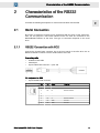
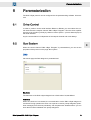
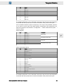
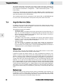
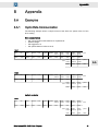
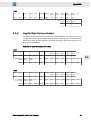
1
SIEB & MEYER
Drive System SD2
DNC 8 Byte Telegram
P-TD-0000147.2
2012-11-02
W
W
Copyright
Copyright © 2012 SIEB & MEYER AG.
All rights reserved.
This manual or extracts thereof may only be copied with the explicit authorization of
SIEB & MEYER AG.
Trademarks
All product, font and company names mentioned in this manual may be trademarks or registered
trademarks of their respective companies.
SIEB & MEYER worldwide
For questions regarding our products and technical problems please contact us.
SIEB & MEYER AG
Auf dem Schmaarkamp 21
D 21339 Lüneburg
Germany
Phone: +49 4131 203 0
Fax: +49 4131 203 2000
[email protected]
http://www.sieb-meyer.com
SIEB & MEYER Asia Co. Ltd.
4 Fl, No. 532, Sec. 1
Min-Sheng N. Road
Kwei-Shan Hsiang
333 Tao-Yuan Hsien
Taiwan
Phone: +886 3 311 5560
Fax: +886 3 322 1224
[email protected]
http://www.sieb-meyer.com
2
SIEB & MEYER Shenzhen Trading Co. Ltd.
1st floor, B room of D1 block, DongNan GongMao
Building
Dongjiaotou Shekou, Houhai Ave, Nanshan District
Shenzhen City, 518067
P.R. China
Phone: +86 755 2681 1417 / +86 755 2681 2487
Fax: +86 755 2681 2967
[email protected]
http://www.sieb-meyer.com
SIEB & MEYER USA, LLC
3975 Port Union Road
Fairfield, OH 45014
USA
Phone: +1 513 563 0860
Fax: +1 513 563 7576
[email protected]
http://www.sieb-meyer.com
Drive System SD2 - DNC 8 Byte Telegram
W
Chapter Overview
General Information
1
Characteristics of the RS232 Communication
2
Data Types
3
DNC Commands
4
Addressing the Devices
5
Parameterization
6
Telegram Structure
7
Appendix
8
Drive System SD2 - DNC 8 Byte Telegram
3
Chapter Overview
4
W
Drive System SD2 - DNC 8 Byte Telegram
W
Content
1
General Information .......................................................... 7
2
Characteristics of the RS232 Communication .................. 9
2.1
Serial Connection ........................................................................................ 9
2.2
2.3
Parameters of the Serial Interface ............................................................ 10
Time Response ......................................................................................... 10
3
Data Types ...................................................................... 13
3.1
3.2
3.3
3.4
1 Byte Data Types ....................................................................................
2 Byte Data Types ....................................................................................
4 Byte Data Types ....................................................................................
3 Byte Data Types ....................................................................................
4
DNC Commands ............................................................. 15
4.1
General Structure of the Command Interface ........................................... 15
5
Addressing the Devices .................................................. 17
6
Parameterization ............................................................. 19
6.1
6.2
Drive Control ............................................................................................. 19
Bus System ............................................................................................... 19
7
Telegram Structure ......................................................... 21
7.1
Description of the DNC 8 Byte Telegram .................................................. 21
7.2
Description of DNC 16 Byte Telegram ...................................................... 22
7.3
Cyclic Data ................................................................................................ 23
2.1.1
2.1.2
4.1.1
4.1.2
7.1.1
7.1.2
7.2.1
7.2.2
RS232 Connection with SD2 ................................................................................... 9
RS232 Connection with SD2S .............................................................................. 10
13
13
13
14
Command Block .................................................................................................... 15
Reply Block ........................................................................................................... 15
DNC 8 Byte Prompt Telegram .............................................................................. 21
DNC 8 Byte Response Telegram .......................................................................... 21
DNC 16 Byte Prompt Telegram ............................................................................ 22
DNC 16 Byte Response Telegram ........................................................................ 22
7.3.1
7.3.2
PDO Header (Byte 6 and 7) .................................................................................. 23
PDO Data .............................................................................................................. 24
7.4
Acyclic Service Data ................................................................................. 26
8
Appendix ......................................................................... 31
8.A
Examples .................................................................................................. 31
7.4.1
7.4.2
7.4.3
7.4.4
7.4.5
8.A.1
8.A.2
8.A.3
Service Control (Byte 17) ......................................................................................
Service Index (Byte 18, 19) ...................................................................................
Service Data (Byte 20…23) ..................................................................................
Service State (Byte 17) .........................................................................................
Error Codes in the Service Data Channel .............................................................
27
27
28
28
28
Cyclic Data Communication .................................................................................. 31
Acyclic Data Communication ................................................................................ 33
Calculation of Check Sum ..................................................................................... 35
Drive System SD2 - DNC 8 Byte Telegram
5
Content
6
W
Drive System SD2 - DNC 8 Byte Telegram
W
1
General Information
General Information
The DNC 8 Byte protocol is used for diagnosis and parameterization of SD2- drives. A
PC can be used for the diagnosis and as parameter interface, interchanging data with
the drive via the DNC 8 Byte protocol .
The following bus systems are supported for the connection of the drive:
< RS232
< RS485
The communication with the SD2 drive is established according to the master-slave
method. The PC acts as master and the drive acts as slave. Thus, the drive is only ac‐
tive on request of the master.
The data are exchanged as data telegrams. The master sends a command telegram to
the slave. When this is received the slave returns a response telegram to the master.
The data are only exchanged via the bus system, when the master initiates the ex‐
change.
The DNC 8 Byte protocol does not have fixed response times. For this rea‐
son it should only be used for parameterization and diagnosis purposes of
the drive.
Drive System SD2 - DNC 8 Byte Telegram
7
1
General Information
W
1
8
Drive System SD2 - DNC 8 Byte Telegram
W
2
Characteristics of the RS232 Communication
Characteristics of the RS232
Communication
2
Consider the following descriptions for serial communication with the SD2.
2.1
Serial Connection
By means of customary PC data can be exchanged with the drive via the serial inter‐
face. For this purpose a free serial interface of the PC must be connected to the
RS232/RS485 interface of the drive. The type of connection depends on the used
drive.
2.1.1
RS232 Connection with SD2
Connect the female RJ45 connector X3 at the front panel of the SD2 drive via an
RS232 to RS485 converter to a free serial interface of the PC.
Connecting cable
<
<
<
shielded round cable
twisted-pair
8-pole male RJ45 connector ↔ open end
Pin assignment on SD2
<
8-pole female RJ45 connector
Pin
I/O
Name
1
–
2
–
3
I/O
D+
4
–
5
–
Meaning
RS485 interface
6
I/O
D−
RS485 interface
7
I/O
GND
Ground
8
I/O
GND
Ground
Drive System SD2 - DNC 8 Byte Telegram
9
W
Characteristics of the RS232 Communication
2.1.2
RS232 Connection with SD2S
Connect X19 (9-pole male submin D connector) at the front panel of the SD2S-drive to
a free serial interface of the PC (9-pole male submin D connector).
Connecting cable
2
<
<
<
shielded round cable
twisted-pair
9-pole female submin D connector ↔ 9-pole female submin D connector
Pin assignment on the device
<
9-pole male submin D connector ↔ 9-pole male submin D connector
SD2S
Name
Pin
I/O
1
PC
I/O
Pin
–
2
I
RxD
Receive data from PC
O
3
3
O
TxD
Transmit data to PC
I
2
Ground
I/O
5
4
5
2.2
Description
–
I/O
GND
6
–
7
–
8
–
9
–
Parameters of the Serial Interface
The following settings are required for the serial interface:
< Baud rate: 57600 bit/s
< Data bits: 8
< Parity: None
< Stop bits: One
< Protocol: none
2.3
Time Response
When a DNC command block has been transmitted, the Drive will respond max.
250 µs after having received the last byte of the command block.
10
Drive System SD2 - DNC 8 Byte Telegram
W
Characteristics of the RS232 Communication
Please note that the transmission time depends on the quantity of data. Therefore the
PC software drivemaster2 uses a timeout of 1 s to make sure that the serial connection
is definitely interrupted.
2
Drive System SD2 - DNC 8 Byte Telegram
11
Characteristics of the RS232 Communication
W
2
12
Drive System SD2 - DNC 8 Byte Telegram
W
3
Data Types
Data Types
The communication with the SD2 is carried out by means of DNC commands. These
commands allow data exchange with the device via memory blocks.
Depending on the DNC command, memory blocks are organized bytewise, wordwise
or 3-bytewise. The following applies for a memory block of the length n:
< <byte 0, word 0, three byte 0> = byte with the lowest address
< <byte n-1, word n-1, three byte n-1 > = byte with the highest address
That means: During sequential transmission of the blocks the <byte 0> must be trans‐
mitted first and the <byte n-1> must be transmitted last.
The following sections describe the data types known by the SD2 and their bytewise
organization.
3.1
1 Byte Data Types
One byte is the smallest data format that can be transmitted with an DNC-command. A
distinction is drawn between unsigned and signed 1 byte data types:
T36_S36_SHORT‐
CARD
unsigned 8-bit number (0 … 255)
T36_S36_SHORT‐
INT
signed 8-bit number (-128 … 127)
These data types are equivalent to the C data types unsigned char and signed char.
3.2
2 Byte Data Types
2 byte data types are coded as below:
Byte 0
Byte 1
Bit 0 … 7
Bit 8 … 15
A distinction is drawn between unsigned and signed data types:
T36_S36_CARDI‐
NAL
unsigned 16-bit number (0 … 65535)
T36_S36_INTEGER
signed 16-bit number (-32768 … 32767)
These data types are equivalent to the C data types unsigned short and signed short.
3.3
4 Byte Data Types
4 byte data types are coded as below:
Byte 0
Byte 1
Byte 2
Byte 3
Bit 0 … 7
Bit 8 … 15
Bit 16 … 23
bit 24 … 31
A distinction is drawn between unsigned and signed data types:
Drive System SD2 - DNC 8 Byte Telegram
13
3
W
Data Types
T36_S36_LONG‐
CARD
unsigned 32-bit number (0 … 4,294,967,295)
T36_S36_LONGINT
signed 32-bit number (-2,147,483,647 … 2,147,483,647)
These data types are equivalent to the C data types unsigned int and signed int.
3
3.4
3 Byte Data Types
The devices of the series SD2 partly use 3-byte data items for internal processes.
Byte 0
Byte 1
Byte 2
Bit 0 … 7
Bit 8 … 15
Bit 16 … 23
The PC can not process this data type. Since some of the DNC commands use 3-byte
data items, they must be represented by the existing PC data types. One 3-byte data
item, for example, can be made up of 3 bytes of the type T36_S36_SHORTCARD. Two
3-byte data items can be replaced by three words of the type T36_S36_CARDINAL.
And four 3-Byte data items can be represented by three double words of the type
T36_S36_LONGCARD.
14
Drive System SD2 - DNC 8 Byte Telegram
W
4
DNC Commands
DNC Commands
In general the DNC communication with the Drive is established by the exchange of
data blocks between the DNC master (PC or PLC) and the slave (Drive).
A DNC command has the following structure:
< Command block (sent from the master to the Drive)
< Response block (sent from the Drive to the master)
A DNC command is always started by the master. The Drive only can react to the DNC
command.
The command and response blocks have a different structure and meaning for each
DNC command. The command block describes the actual DNC command and may
contain so-called sub commands.
4.1
General Structure of the Command Interface
Below the general structure of the command and reply telegram is described.
4.1.1
4.1.2
Command Block
Offset
Type
Name
Description
0x00
T36_S36_SHORTCARD
Zero
Start signal for a command transmission: It is always set
to zero.
0x01
T36_S36_SHORTCARD
Length
Protocol length in bytes: It is calculated by the number
of the transmitted data, but except of the leading zero,
the checksum and the length specification. The smallest
length is 3.
0x02
T36_S36_SHORTCARD
Dest
Destination of the command block: It contains the de‐
sired module number plus 2.
0x03
T36_S36_SHORTCARD
Src
Transmitter of the commands: Here the value 1 is en‐
tered for the PC or PLC.
0x04
T36_S36_SHORTCARD
cmd
Command number of the actual DNC command
0x05
T36_S36_SHORTCARD
array with a maximum
length of 48 bytes
Data
User data of the command: Depending on the command
up to 48 bytes, 24 words or 16 3-byte words can be
transmitted.
0x05 +
length-3
T36_S36_SHORTCARD
Check
Check sum: It consists of the ones complement of the
sum of the complete data block, except of the check‐
sum.
Reply Block
Offset
Type
Name
Description
0x00
T36_S36_SHORTCARD
Zero
Start signal for the reply transmission: It is always set to
zero.
0x01
T36_S36_SHORTCARD
Length
Protocol length in bytes: It is calculated by the number
of the transmitted data, but except of the leading zero,
the checksum and the length specification. The smallest
length is 3.
0x02
T36_S36_SHORTCARD
Dest
Destination of the reply block: Here the value 1 is en‐
tered for the PC or PLC.
Drive System SD2 - DNC 8 Byte Telegram
15
4
W
DNC Commands
Offset
Type
Name
Description
0x03
T36_S36_SHORTCARD
Src
Transmitter the reply block: It contains the module num‐
ber of the transmitter plus 2.
0x04
T36_S36_SHORTCARD
cmd
Number of the executed command: Note, that the most
significant bit is additionally set to 1.
0x05
T36_S36_SHORTCARD
array with a maximum
length of 48 bytes
Data
User data of the reply block: Depending on the com‐
mand up to 48 bytes, 24 words or 16 3-byte words can
be transmitted.
0x05 +
length-3
T36_S36_SHORTCARD
Check
Check sum: It consists of the ones complement of the
sum of the complete data block, except of the check
sum.
4
16
Drive System SD2 - DNC 8 Byte Telegram
W
5
Addressing the Devices
Addressing the Devices
In order to control the drives via PLC or an appropriate PC program the DNC address‐
es used in the DNC protocol must be known. The DNC drive addresses are derived
from the module addresses that are set by means of the address selection switch on
each device. Via the module address the software drivemaster2 communicates with
the devices.
For more information on proper addressing of the modules refer to the docu‐
mentation "drivemaster2 User Manual", chapter "Communication".
In the DNC protocol each device (double-axis devices and single-axis devices) has al‐
ways two DNC addresses, that means the master communicates with drive A via the
lower DNC address and with drive B via the higher DNC address. Single-axis devices
do not have a drive B. Therefore the higher DNC address is not used. The DNC ad‐
dresses 0 and 1 are reserved for the master. For this reason the numbering starts with
the DNC address 2.
The DNC address of a drive can be calculated from the position of the address selec‐
tion switch on the module by means of the following formula:
DNC address drive A = (address selection switch × 2) + 2
DNC address drive B = (address selection switch × 2) + 3
The following figure illustrates the relation of the drive address used in drivemaster2
and the drive address used in the DNC protocol:
Fig. 1: Drive addresses in drivemaster2 and in the DNC protocol
Drive System SD2 - DNC 8 Byte Telegram
17
5
Addressing the Devices
W
5
18
Drive System SD2 - DNC 8 Byte Telegram
W
6
Parameterization
Parameterization
The DNC 8 Byte protocol can be configured via the parameterizing software drivemas‐
ter2.
6.1
Drive Control
In order to position via the serial interface RS232 or RS485, you must select the con‐
trol channel and the setpoint channel "DNC 8 Byte Telegram". Thus the drive amplifier
expects to be supplied cyclically by reference values (PDOs – process data object) via
the serial interface.
Acyclic communication is independent of the setpoint channel and works always.
6.2
Bus System
6
When the control channel "DNC 8 Byte Telegram" is parameterized, you can set the
properties of the protocol on the page "Bus system".
DNC
Via this tab page the DNC telegram is parameterized.
Baud rate
The baud rate of the DNC 8 byte telegram has a fixed value of 57,600 kBaud.
Heartbeat
When the check box is activated, the communication via the DNC 8 Byte telegram is
monitored. During operation the drive now expects to receive prompt telegrams (heart‐
beat messages) from the host periodically. Via the parameter "Heartbeat time" you can
enter the time interval between two prompt telegrams.
Drive System SD2 - DNC 8 Byte Telegram
19
W
Parameterization
Heartbeat time
The parameter indicates the maximum length of time in milliseconds, in which a heart‐
beat message must be sent to the drive during operation. If the drive does not receive
a message within this time, an error is triggered.
PDO 0
The tab pages "PDO 0" and "PDO 1" display the assignment of the individual drive ob‐
jects (functions) in the DNC telegram.
6
There is only this one PDO in the DNC 8 Byte Telegram.
Receive PDO
The Receive PDO displays the received data. The data can not be changed.
Transmit PDO
The Transmit PDO displays the transmitted data. Here you can set when and in which
form the data are sent.
The following settings are available:
< Disabled:
No data are sent.
< At receive of RPDO 0:
The drive sends the adjacent data, when it is requested for them by a Re‐
ceive PDO from the master.
20
Drive System SD2 - DNC 8 Byte Telegram
W
Telegram Structure
7
Telegram Structure
7.1
Description of the DNC 8 Byte Telegram
Via the command 16 (0x10) "Write CAN Message" of the serial DNC communication
PDOs (process data object) are exchanged between master and drive. The user data
correspond to the data of the SD2 CAN connection.
The telegram has the following structure:
< Header (5 bytes)
< CAN Header (2 bytes)
< Data area (8 bytes)
< Check sum (1 byte)
7.1.1
DNC 8 Byte Prompt Telegram
Byte
Name
Value
Protocol
1
zero
0
DNC
2
Length
13
DNC
3
dest
DNC address
DNC
4
Source
1 for PC
DNC
5
cmd
0x10 (const)
DNC
6
PDO Header
PDO Header 0
Cyclic channel
7
PDO Header
PDO Header 1
Cyclic channel
8
PDO Data
PDO Data 0
Cyclic channel
⋮
PDO Data
⋮
Cyclic channel
15
PDO Data
PDO Data 7
Cyclic channel
16
Check(1)
Checksum
DNC
7
(1) Check = 0xFF - (sum of the bytes 2 to 15)
For an example of the check sum calculation see Appendix, p. 35.
7.1.2
DNC 8 Byte Response Telegram
Byte
Name
Value
Protocol
1
zero
0
DNC
2
Length
13 (if CAN message available)
DNC
3
dest
1 for PC
DNC
4
Source
DNC address
DNC
5
cmd
0x90 (const)
DNC
6
PDO Header
PDO Header 0
Cyclic channel
7
PDO Header
PDO Header 1
Cyclic channel
8
PDO Data
PDO Data 0
Cyclic channel
⋮
PDO Data
⋮
Cyclic channel
15
PDO Data
PDO Data 7
Cyclic channel
Drive System SD2 - DNC 8 Byte Telegram
21
W
Telegram Structure
Byte
16
Name
Value
Protocol
Check(1)
Checksum
DNC
(1) Check = 0xFF - (sum of the bytes 2 to 15)
For an example of the check sum calculation see Appendix, p. 35.
7.2
Description of DNC 16 Byte Telegram
The DNC 16 Byte telegram is an extended DNC 8 Byte telegram, in which 8 bytes noncyclic data are added.
The protocol structure corresponds to the DNC 8 Byte telegram. The acyclic data are
recognized via the length of the protocol (length byte).
In the following the telegram structure is described.
7.2.1
DNC 16 Byte Prompt Telegram
Byte
7
Name
Value
Protocol
1
zero
0
DNC
2
Length
21
DNC
3
dest
DNC address
DNC
4
Source
1 for PC
DNC
5
cmd
0x10 (const)
DNC
6
PDO Header
PDO Header 0
Cyclic channel
7
PDO Header
PDO Header 1
Cyclic channel
8
PDO Data
PDO Data 0
Cyclic channel
⋮
PDO Data
⋮
Cyclic channel
15
PDO Data
PDO Data 7
Cyclic channel
16
Service Control
Not used (0)
Acyclic service data
17
Service Control
Service Control
Acyclic service data
18
Service Index
Service Index 0
Acyclic service data
19
Service Index
Service Index 1
Acyclic service data
20
Service Data
Service Data 0
Acyclic service data
⋮
Service Data
⋮
Acyclic service data
23
Service Data
Service Data 3
Acyclic service data
24
Check(1)
Checksum
DNC
(1) Check = 0xFF - (sum of the bytes 2 to 23)
For an example of the check sum calculation see Appendix, p. 35.
7.2.2
DNC 16 Byte Response Telegram
Byte
22
Name
Value
Protocol
1
zero
0
DNC
2
Length
21 (if CAN message available)
DNC
3
dest
1 for PC
DNC
4
Source
DNC address
DNC
Drive System SD2 - DNC 8 Byte Telegram
W
Telegram Structure
Byte
Name
Value
Protocol
5
cmd
0x90 (const)
DNC
6
PDO Header
PDO Header 0
Cyclic channel
7
PDO Header
PDO Header 1
Cyclic channel
8
PDO Data
PDO Data 0
Cyclic channel
⋮
PDO Data
⋮
Cyclic channel
15
PDO Data
PDO Data 7
Cyclic channel
16
Service State
Not used (0)
Acyclic service data
17
Service State
Status
Acyclic service data
18
Service Index
Service Index 0
Acyclic service data
19
Service Index
Service Index 1
Acyclic service data
20
Service Data
Service Data 0
Acyclic service data
⋮
Service Data
⋮
Acyclic service data
23
Service Data
Service Data 3
Acyclic service data
24
Check(1)
Checksum
DNC
(1) Check
= 0xFF - (sum of the bytes 2 to 23)
For an example of the check sum calculation see Appendix, p. 35.
7.3
Cyclic Data
7.3.1
PDO Header (Byte 6 and 7)
Bit
7
Control telegram
Status telegram
0
NMT command bit 0
NMT command bit 0
1
NMT command bit 1
NMT command bit 1
2
Toggle bit
Toggle bit
3
PDO selection bit 0
PDO selection bit 0
4
PDO selection bit 1
PDO selection bit 1
5
PDO selection bit 2
PDO selection bit 2
6
0
0
⋮
0
0
15
0
0
NMT command
The communication of the drive is controlled by the communication state machine
(NMT state machine). The state machine can be controlled via the network manage‐
ment (NMT) protocol.
The following commands are supported:
Command
Meaning
0
No action
1
Switches NMT to the state operational
2
Switches NMT to the state pre-operational
3
No action
Heartbeat monitoring is only executed in the state "NMT operational". If so, the PDO
data can be exchanged.
Drive System SD2 - DNC 8 Byte Telegram
23
W
Telegram Structure
Toggle bit
The bit must be toggled (switched over/ inverted) during the parameterized monitoring
time (Watchdog timeout), otherwise an error is triggered. Then the axis adapts the tog‐
gled bit again. Thus it can be toggled again.
PDO selection
The PDO selection defines the way in which the user data will be interpreted. Via the
3 bits you can select PDO 0 to PDO 7. Since currently only PDO 0 is used, the bits
Bits 3, 4 and 5 in the PDO Header must be 0.
PDO
0
7
7.3.2
Meaning
Cyclic process data
1
Not used
2
Not used
3
Not used
4
Not used
5
Not used
6
Not used
7
Not used
PDO Data
PDO Data contains the user data according to the selected PDO (currently only
PDO 0).
PDO 0: cyclic exchange of process data
Control telegram:
Byte
Name
8
PDO data 0
9
PDO data 1
10
PDO data 2
11
PDO data 3
12
PDO data 4
13
PDO data 5
14
PDO data 6
15
PDO data 7
Description
Control Word
Normalized reference speed
0
0
Control word (byte 8 and 9):
Bit
24
Name
0
Switch On
1
Enable Voltage
2
Quick Stop
3
Enable Operation
4
Mode 0
5
Mode 1
6
Mode 2
7
Fault Reset
Drive System SD2 - DNC 8 Byte Telegram
W
Telegram Structure
Bit
Name
8
Hold
9
Reserved
10
Reserved
11
Reserved
12
Reserved
13
Reserved
14
Reserved
15
Reserved
For detailed information on the individual control bits and the finite state automaton
connected with these please refer to the documentation "SD2_DeviceControl.pdf".
The normalized reference speed corresponds to the object SPG_TARGET_VELOCI‐
TY_VL and is a 16 bit value. The value 0x3FFF corresponds to the speed that is en‐
tered in the software drivemaster2 in "Configuration ÿ Motor measurement system ÿ
Velocity scaling".
Status telegram:
Byte
Name
8
PDO data 0
9
PDO data 1
10
PDO data 2
11
PDO data 3
12
PDO data 4
13
PDO data 5
14
PDO data 6
15
PDO data 7
Description
Status word
7
Normalized actual speed
Drive error
Normalized actual current
Status word (byte 8 and 9):
Bit
Name
0
Ready to switch on
1
Switched on
2
Operation enabled
3
Fault
4
Voltage enabled
5
Quick Stop
6
Switch on disabled
7
Warning
8
Reserved
9
Remote
10
Target reached
11
Internal limit active
12
Speed zero
13
Max target torque reached
14
Reserved
15
Reserved
For detailed information on the individual control bits and the finite state automaton
connected with these please refer to the documentation "SD2_DeviceControl.pdf".
Drive System SD2 - DNC 8 Byte Telegram
25
Telegram Structure
W
The actual speed value corresponds to the object VCTRL_VELOCITY_ACTUAL_VA‐
LUE and is a 16 bit value. The value 0x3FFF corresponds to the speed that is entered
in the software drivemaster2 in "Configuration ÿ Motor measurement system ÿ Ve‐
locity scaling".
A drive error corresponds to the object DEV_CTRL_ERROR_CODE_LATCHED and is
a 16 bit value. A list comprising the error messages of the drive is to find in the hard‐
ware documentation of your used hardware.
The normalized actual current corresponds to the object ICTRL_IQ_REFERENCE and
is a 16 bit value. The value 0x3FFF corresponds to the peak current of the drive.
7.4
Acyclic Service Data
In addition to the process data channel (PDO 0) the acyclic channel can be used as
service data channel to access all objects in the drive. This service channel is only
available in the "DNC 16 Byte telegram".
The following accesses are available:
< Reading an object:
The read access is controlled in the service data channel via 'ServiceFunction = 0
(byte 17)'. Via Index low/high the corresponding object is selected. The result of
the read access is returned in the response service data channel. Via array in‐
dex 0…3 a subindex can be transmitted.
< Setting an array index:
The setting of an array index is controlled in the service data channel 'Service‐
Function = 1 (byte 17)'. Via Index low/high the corresponding object is selected.
Via array index 0…3 the array index is transmitted.
< Writing an object:
The write access is controlled in the service data channel via 'ServiceFunc‐
tion = 2'. Via Index low/high the corresponding object is selected and byte 20…
byte 23 contain the according value. Via ServiceLastValidByteIndex the number of
valid bytes (minus 1) in this telegram must be defined.
7
Writing of arrays
There are max. 32 bit user data available in the service data channel. For this reason
only objects with a maximum size of 32 bit can be written.
If objects of a larger size shall be written, e.g. arrays, an additional mechanism is nec‐
essary. In order to write arrays at first the corresponding array index must be ad‐
dressed. The array index is addressed in the service data channel via 'ServiceFunc‐
tion = 1' (Set Array Index). The drive acknowledges the telegram by returning the re‐
ceived array index in the actual value telegram. In one of the following reference value
telegrams 1 to 4 bytes can be written into the array via the command 'ServiceFunc‐
tion = 2' (Write Object). The array index saved in the device is automatically increased
by the written number of bytes. Thus it is possible to write the array consecutively with
a new command 'ServiceFunction = 2' (Write Object) in one of the following telegrams.
Since there is only one variable available in the drive to save the actual array index, a
nested access to two arrays is not possible e.g. write array A, write array B, write array
A etc.
Reading of arrays
During the reading of array objects the array index is transmitted in each reference va‐
lue telegram. For this reason setting an array index is not necessary. The variable
saved in the drive is not increased by read access. Therefore the read access to an
array does not interrupt the incremental writing of the array.
26
Drive System SD2 - DNC 8 Byte Telegram
W
Telegram Structure
Error during object access
When the access to a drive object is faulty (index is not valid, range of values is excee‐
ded, object is not writable etc.), this error is indicated in the actual value telegram via
the signal ServiceFault. In addition the detailed error number is returned via Service‐
Return.
7.4.1
Service Control (Byte 17)
Service Control:
Bit
Description
0
–
1
ServiceFunction bit 0
2
ServiceFunction bit 1
3
ServiceLastValidByteIndex bit 0
4
ServiceLastValidByteIndex bit 1
5
–
6
–
7
–
ServiceFunction bit 1, 2:
< 0 = Read Object
< 1 = Set Array Index
< 2 = Write Object
< 3 = free → fault
7
ServiceLastValidByteIndex bit 3, 4:
Number of valid bytes:
< 0 = 1 byte
< 1 = 2 bytes
< 2 = 3 bytes
< 3 = 4 bytes
Depending on the service function the bytes are interpreted differently in the control
telegram. The following table indicates the structure of the data in dependance on the
service function.
Control telegram:
Byte
7.4.2
Control telegram
Read Object (0)
Write Object (2)
Set Array Index (1)
16
Not used
–
–
–
17
Service Control
Service Control
Service Control
Service Control
18
Service Index 0
Index low
Index low
Not used
19
Service Index 1
Index high
Index high
Not used
20
Service Data 0
Array Index 0
Byte 0
Array Index 0
21
Service Data 1
Array Index 1
Byte 1
Array Index 1
22
Service Data 2
Array Index 2
Byte 2
Array Index 2
23
Service Data 3
Array Index 3
Byte 3
Array Index 3
Service Index (Byte 18, 19)
The Service Index is the object index of the object to be accessed.
Drive System SD2 - DNC 8 Byte Telegram
27
W
Telegram Structure
7.4.3
Service Data (Byte 20…23)
Service Data contains either the data bytes to be written in an object or the subindex
for the object access.
7.4.4
Service State (Byte 17)
Service State:
Bit
Description
0
–
1
ServiceFault
2
–
3
–
4
–
5
–
6
–
7
–
Depending on the executed service function and the service status the bytes in the sta‐
tus telegram have different meanings. The following table indicates the structure of the
data in dependance on the service function and the service status.
7
Status telegram:
Byte
7.4.5
28
Status telegram
Read Object (0)
Write Object (2)
Set Array Index (1)
16
Not used
–
–
–
17
Service State
Service State
Service State
Service State
18
Service Index 0
Index low
Index low
Not used
19
Service Index 1
Index high
Index high
Not used
20
Service Data 0
Byte 0 / error code
Array Index 0 / error
code
Array Index 0
21
Service Data 1
Byte 1 / error code
Array Index 1 / error
code
Array Index 1
22
Service Data 2
Byte 2 / error code
Array Index 2
Array Index 2
23
Service Data 3
Byte 3 / error code
Array Index 3
Array Index 3
Error Codes in the Service Data Channel
Error code
Description
0x00
no error
0x81 or 0x01
Toggle bit not alternated
0x86 or 0x06
CRC error
0x87 or 0x07
No free memory
0x88 or 0x08
Unsupported access to an object
0x89 or 0x09
Attempt to read a write-only object
0x8A or 0x0A
Attempt to write in a read-only object
0x8B or 0x0B
Object does not exist in the object directory!
0x8C or 0x0C
Reserved
0x8D or 0x0D
Reserved
Drive System SD2 - DNC 8 Byte Telegram
W
Telegram Structure
Error code
Description
0x8E or 0x0E
General parameter incompatibility reason
0x8F or 0x0F
General internal incompatibility in the device
0x90 or 0x10
Access failed due to hardware error
0x91 or 0x11
Data type not correct, length of the service parameter not correct
0x92 or 0x12
Data type not correct, length of the service parameter too long
0x93 or 0x13
Data type not correct, length of the service parameter too short
0x94 or 0x14
Subindex does not exist
0x95 or 0x15
Value range of the parameter exceeded (only for write access)
0x96 or 0x16
Value of the written parameter too high
0x97 or 0x17
Value of the written parameter too low
0x98 or 0x18
Maximum is less than minimum value
0x99 or 0x19
General error
0x9A or 0x1A
Data can not be transmitted or saved in the application.
0x9B or 0x1B
Data can not be transmitted or saved in the application due to the status of the
control.
0x9C or 0x1C
Data can not be transmitted or saved in the application due to the reset device.
0x9D or 0x1D
Dynamic generation of the object directory not possible or no object directory
existing
0x9E or 0x1E
Read access denied
0x9F or 0x1F
Write access denied
Drive System SD2 - DNC 8 Byte Telegram
7
29
Telegram Structure
W
7
30
Drive System SD2 - DNC 8 Byte Telegram
W
Appendix
8
Appendix
8.A
Examples
8.A.1
Cyclic Data Communication
The following example shows a simple control of the drive at a speed of 50 % of the
drive scaling.
Start communication
<
<
<
<
Set communication state machine to "operational".
Enable voltage.
Set toggle bit to 0.
Set speed reference value to 50 %.
Send:
zero
len
dest
Source
cmd
header
0
header
1
PDO
Data 0
PDO
Data 1
PDO
Data 2
PDO
Data 3
PDO
Data 4
0x00
0x0d
0x02
0x01
0x10
0x01
0x00
0x06
0x00
0xFF
0x1f
0x00
PDO
Data 5
PDO
Data 6
PDO
Data 7
psum
0x00
0x00
0x00
0xba
●●●
●●●
●●●
8.A
Reply:
zero
len
dest
Source
cmd
header
0
header
1
PDO
Data 0
PDO
Data 1
PDO
Data 2
PDO
Data 3
PDO
Data 4
0x00
0x0d
0x01
0x02
0x90
0x01
0x00
0x31
0x72
0x00
0x00
0x00
PDO
Data 5
PDO
Data 6
PDO
Data 7
psum
0x00
0x00
0x00
0xbb
●●●
●●●
Activate controller
Send:
zero
len
dest
Source
cmd
header
0
header
1
PDO
Data 0
PDO
Data 1
PDO
Data 2
PDO
Data 3
PDO
Data 4
0x00
0x0d
0x02
0x01
0x10
0x01
0x00
0x07
0x00
0xff
0x1f
0x00
PDO
Data 5
PDO
Data 6
PDO
Data 7
psum
0x00
0x00
0x00
0xb9
●●●
Drive System SD2 - DNC 8 Byte Telegram
31
W
Appendix
Reply:
zero
len
dest
Source
cmd
header
0
header
1
PDO
Data 0
PDO
Data 1
PDO
Data 2
PDO
Data 3
PDO
Data 4
0x00
0x0d
0x01
0x02
0x90
0x01
0x00
0x33
0x72
0x00
0x00
0x00
PDO
Data 5
PDO
Data 6
PDO
Data 7
psum
0x00
0x21
0x43
0x55
●●●
●●●
●●●
Operation enable
<
Toggle bit has been toggled.
Send:
zero
len
dest
Source
cmd
header
0
header
1
PDO
Data 0
PDO
Data 1
PDO
Data 2
PDO
Data 3
PDO
Data 4
0x00
0x0d
0x02
0x01
0x10
0x05
0x00
0x0f
0x00
0xff
0x1f
0x00
PDO
Data 5
PDO
Data 6
PDO
Data 7
psum
0x00
0x00
0x00
0xad
●●●
●●●
8.A
Reply:
zero
len
dest
Source
cmd
header
0
header
1
PDO
Data 0
PDO
Data 1
PDO
Data 2
PDO
Data 3
PDO
Data 4
0x00
0x0d
0x01
0x02
0x90
0x05
0x00
0x37
0x72
0xff
0x1f
0x00
PDO
Data 5
PDO
Data 6
PDO
Data 7
psum
0x00
0x21
0x43
0x2f
●●●
●●●
Deactivate controller
<
Toggle bit has been toggled.
Send:
zero
len
dest
Source
cmd
header
0
header
1
PDO
Data 0
PDO
Data 1
PDO
Data 2
PDO
Data 3
PDO
Data 4
0x00
0x0d
0x02
0x01
0x10
0x01
0x00
0x06
0x00
0xff
0x1f
0x00
PDO
Data 5
PDO
Data 6
PDO
Data 7
psum
0x00
0x00
0x00
0xba
●●●
32
Drive System SD2 - DNC 8 Byte Telegram
W
Appendix
Reply:
zero
len
dest
Source
cmd
header
0
header
1
PDO
Data 0
PDO
Data 1
PDO
Data 2
PDO
Data 3
PDO
Data 4
0x00
0x0d
0x01
0x02
0x90
0x01
0x00
0x31
0x72
0x00
0x00
0x00
PDO
Data 5
PDO
Data 6
PDO
Data 7
psum
0x00
0x21
0x43
0x57
●●●
8.A.2
●●●
Acyclic Data Communication
In addition to the cyclic data there are acyclic data attached to the data protocol. The
content of the cyclic part of the data must still be set according to the current operating
status of the drive. For this example we consider the drive in the status 'ready for oper‐
ation' but not switched on.
Read-out of object 33 (voltage of the bus)
Send:
zero
len
dest
Source
cmd
header
0
header
1
PDO
Data 0
PDO
Data 1
PDO
Data 2
PDO
Data 3
PDO
Data 4
0x00
0x15
0x02
0x01
0x10
0x01
0x00
0x06
0x00
0xff
0x1f
0x00
PDO
Data 5
PDO
Data 6
PDO
Data 7
0
ctrl
index
0
index
1
s-data
0
s-data
1
s-data
2
s-data
3
psum
0x00
0x00
0x00
0x00
0x08
0x21
0x00
0x00
0x00
0x00
0x00
0x89
zero
len
dest
Source
cmd
header
0
header
1
PDO
Data 0
PDO
Data 1
PDO
Data 2
PDO
Data 3
PDO
Data 4
●●●
0x00
0x15
0x01
0x02
0x90
0x01
0x00
0x31
0x72
0x00
0x00
0x00
PDO
Data 5
PDO
Data 6
PDO
Data 7
0
ctrl
index
0
index
1
s-data
0
s-data
1
s-data
2
s-data
3
psum
0x00
0xec
0xff
0x00
0x01
0x21
0x00
0xbf
0x0c
0x00
0x00
0xdb
●●●
●●●
8.A
Reply:
●●●
Drive System SD2 - DNC 8 Byte Telegram
33
W
Appendix
Writing of object 352 (parameter set selection):
Send:
zero
len
dest
Source
cmd
header
0
header
1
PDO
Data 0
PDO
Data 1
PDO
Data 2
PDO
Data 3
PDO
Data 4
0x00
0x15
0x02
0x01
0x10
0x01
0x00
0x06
0x00
0xff
0x1f
0x00
PDO
Data 5
PDO
Data 6
PDO
Data 7
0
ctrl
index
0
index
1
s-data
0
s-data
1
s-data
2
s-data
3
psum
0x00
0x00
0x00
0x00
0x0d
0x60
0x01
0x01
0x00
0x00
0x00
0x43
zero
len
dest
Source
cmd
header
0
header
1
PDO
Data 0
PDO
Data 1
PDO
Data 2
PDO
Data 3
PDO
Data 4
●●●
0x00
0x15
0x01
0x02
0x90
0x01
0x00
0x31
0x72
0x00
0x00
0x00
PDO
Data 5
PDO
Data 6
PDO
Data 7
0
ctrl
index
0
index
1
s-data
0
s-data
1
s-data
2
s-data
3
psum
0x00
0x21
0x43
0x00
0x00
0x60
0x01
0x01
0x00
0x00
0x00
0xed
●●●
●●●
Reply:
●●●
8.A
34
Drive System SD2 - DNC 8 Byte Telegram
W
8.A.3
Appendix
Calculation of Check Sum
Example code:
// example receive buffer filled with data from communication example 1:
char receiveBuffer[] = {0x00,0x0d,0x01,0x02,0x90,0x01,0x00,0x31,0x72,0x00,0x00,0x00,0x00,0x00,0x00,0xbb};
// this function creates the checksum
unsigned char CheckSumm (char * receiveBuffer)
{
unsigned char Summ = 0;
// start value for the checksum
int i;
// loop counter
int length = receiveBuffer[1];
// amount of bytes to create checksum
int lastIndex = length + 2;
// last valid index for checksum loop
for( i=1 ; i<lastIndex ; i++ )
// loop run from "length" byte to last "data" byte
{
Summ += receiveBuffer[i];
// add new value to last result
}
return (0xff - Summ);
}
8.A
// this function compares calculated checksum with received checksum from receive buffer
bool CompareCheckSumm(void)
{
int length = receiveBuffer[1];
// length of checksum data
int checksummoffset = length + 2;
// index in the array where the checksum is saved
if ( receiveBuffer[checksummoffset] == CheckSumm( &receiveBuffer[0] ) )
return true;
// compare received checksum with calculated checksum
else
return false;
}
Drive System SD2 - DNC 8 Byte Telegram
35
Appendix
W
8.A
36
Drive System SD2 - DNC 8 Byte Telegram