1
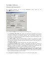
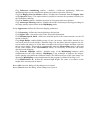
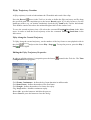
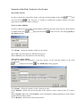
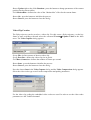
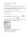
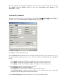
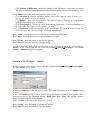
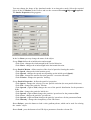
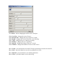
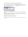
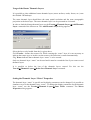
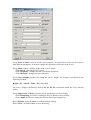
ScanEx IMAGE Processor version 1.0
TERRAIN Module
ScanEx IMAGE Processor version 1.0........................................................................................1
TERRAIN Module ......................................................................................................................1
3D Terrain Creation.....................................................................................................................3
3D Terrain Viewing Mode ..........................................................................................................6
Terrain Mode Toolbar .............................................................................................................7
The Terrain Module Main Menu .............................................................................................8
Status bar ...............................................................................................................................10
The Module’s Preferences .........................................................................................................11
Setting the rendering parameters ...........................................................................................11
Level of Detail Control for the 3D Terrain Display ..............................................................13
Camera Motion Control.........................................................................................................14
Flyby Trajectory Creation .........................................................................................................15
Editing the Flyby Trajectory Properties ................................................................................15
Properties of the Flyby Trajectory’s Key Frames .................................................................16
Video Clip Creation...............................................................................................................17
Operations with the 3D Objects and Models.............................................................................18
Cloud and Fog Simulation.....................................................................................................19
Creation of the 3D Object – “Smoke” ...................................................................................20
Creation of Trees ...................................................................................................................22
Creation of the 2D Textures with the Horizontal Disposition (Sticker)................................25
Editing and Manipulating the 3D Objects and Models Placed..................................................26
Adding a copy of a 3D object or model ................................................................................26
Selecting the 3D Objects .......................................................................................................27
Deletion of the 3D Objects Placed ........................................................................................27
Changing the Location of the 3D Objects .............................................................................27
Changing the Size of 3D Objects ..........................................................................................28
Disabling of the 3D Object Selection ....................................................................................28
Creation of the 3D Model Animation....................................................................................28
Usage of the Vector and Raster Thematic Layers .....................................................................30
Adding Vector Layers ...........................................................................................................30
Usage of the Raster Thematic Layers....................................................................................31
Setting the Thematic Layer “Water” Properties ....................................................................31
The TERRAIN Module is a powerful tool providing for the 3D terrain modeling and display.
An Elevation map and the RGB texture are the main elements of the 3D terrain model.
Raster digital elevation models (DEM) and digital elevation models in the GRID format are
used as the Elevation maps. The elevation values can be stored in the both integer and real
format. This application is intended for the following types of digital elevation models:
•
•
•
•
•
•
•
Digital elevation models in the SURFER GRID format.
Digital elevation models in the ArcInfo ASCII GRID format.
Digital elevation models in the ArcInfo Binary GRID format.
Digital elevation models in the USGS DEM format.
Digital model SRTM (Shuttle Radar Topography Mission).
Digital model GTOPO30.
Digital elevation models in the supported raster formats (GeoTIFF, ESRI BIL\BSQ,
ERDAS Imagine IMG, etc.) for which elevations are defined as brightness values.
Digital elevation models can be presented in any of the supported coordinate systems.
For the RGB textures space and aerial images are used. There is a possibility to create 3D
terrain models based on images of various types and resolution without their reduction to the
single spatial resolution.
In order to make 3D Terrain more realistic you may place 3D objects (buildings, trees, vehicles,
etc.) on it. The 3D models can be imported to the application in the exchange format of the 3D
Studio MAX (*.3ds) package.
In addition the embedded algorithms allow to interactively create certain 3D objects like trees,
clouds or smoke. The 2D textures of both the vertical (sprite) and horizontal (sticker)
arrangement may be also used.
There is also a possibility of displaying thematic maps (e.g. vegetation maps, thermal maps,
etc.). Thematic maps may be represented as the vector layers in the Mapinfo MIF and ESRI
SHP formats as well as the binary raster masks.
3D Terrain Creation
A procedure of creating a 3D Terrain is as follows:
1. Create a Working project and load data (a digital elevation model and an image to be
used as the RGB texture).
2. Fulfill an image geometrical correction if it has not been done yet.
3. Set a color palette for the RGB texture.
4. Set the working area (Extent).
5. Use command TerrainÎCreate Terrain of the Main menu. The Create Terrain dialog
appears.
Group Channels defines the RGB texture and the elevation map:
List Red : defines the RGB texture’s red channel.
List Green : defines the RGB texture’s green channel.
List Blue : defines the RGB texture’s blue channel.
List Height : defines the elevation map.
Group Terrain Maps defines the sky’s texture and the texture to be used for the sharpness
increase while zooming:
List Sky Map : defines the sky texture file. Sky textures can be in the BMP, JPG, GIF and
TGA formats and the picture size is a degree of 2.
List Detail Map : specifies a file with the highly detailed texture. These files can be in the
BMP, JPG, GIF and TGA formats and the picture size is a degree of 2.
In this application the Wavelet transform is used to compress elevation maps and RGB textures.
Due to compression the 3D terrain volume decreases up to 30 times almost without losses in the
image quality.
Group Relief Format defines the compression type for the elevation map:
Switch Plain switches off the compression mode and the elevation map is loaded in the
float32 format. We do not recommend this option for large terrain creation.
Switch MRA switches on the Wavelet transform compression mode.
Group Landscape Texture Format defines the compression type for the RGB texture.
Switch Plain switches off the compression mode. In this case 4 bytes of the video buffer are
allocated for 1 pixel of the RGB texture. We do not recommend this option for large terrain
creation.
Switch MRA switches on the Wavelet transform compression mode.
Switch None switches off the RGB texture usage.
Flag PCA enables a mode of the RGB texture principal component analysis and subsequent
compression based on each component Wavelet transform. This option reduces the 3D
terrain volume due to the various ratio compression of the extracted principal components
with. As the second and third principal components (PC2 and PC3) are less informative than
the first one (PC1), it is possible to increase the compression ratio for the second and third
components almost without losses in the image quality as a whole.
Group Quantizers for MRA defines parameters for the Wavelet compression of elevation maps
and RGB textures.
Field Relief : defines a compression ratio for the elevation map. Small values reduce the
compression ratio and the high ones - increase.
Field RGB : defines a compression ratio for the RGB texture; in case of enabling principal
components analysis - the compression ratio for the 1st principal component (PC1).
Field PC2 : defines a compression ratio for the 2nd principal component (PC2).
Field PC3 : defines a compression ratio for the 3rd principal component (PC3).
Groups Layer Resolution and Texture Resolution are used for creating 3D terrains with
various RGB textures' resolution and the elevation maps’ grid step. This option provides for a
possibility of creating a 3D scene with many levels of detail, i.e. a «basic layer» (an RGB
texture and an elevation map) with one spatial resolution and the layers with better spatial
resolution («detail layers») are created. For example, when creating a 3D scene for a certain
administrative district the RGB texture with a resolution of 30 m/pixel and a detailed insert for a
large city with a resolution of 1 m/pixel are used.
Group Layer Resolution defines spatial resolution of a «detail layer» relative to the «basic
layer». The value 1х means that there is no zoom, the value 32x corresponds to the 32-fold zoom
relative to the «basic layer».
Group Texture Resolution defines spatial resolution of the RGB texture relative to the zoom
factor of the «detail layer». This option provides for unloading both the Central processor
(CPU) and the Graphical processor (GPU) when displaying a 3D scene due to reducing level of
detail during this elevation map unpacking and visualization. E.g. a 3D scene is to be compiled
from a «basic layer» with a resolution of 30 m/pixel and a «detail layer» with a 4 m/pixel
resolution. There are two ways of solving this task. The first one is to define Layer Resolution
as 8х for the «detail layer». Thus, the whole «detail layer» including the RGB texture and the
elevation map will have eight times more details compared to the «basic layer» (30 / 8 = 3.75
m/pixel). The second way is to set the Layer Resolution equal to 4х and the Texture
Resolution - to 2х. In this case the elevation map will have twice more details (30 / 4 = 7.5
m/pixel) and the RGB texture will have eight times more details compared to the «basic layer»
((30 / (2*4) = 3.75 m/pixel).
Group Sun defines the Sun position for the shadow calculation.
Field Azimuth : defines the Sun azimuth in degrees.
Field Elevation : defines the Sun elevation in degrees.
Field Ambient : defines the background illumination.
Group Layer defines navigation around the layers.
Button Previous : press the button to move to the previous layer.
Button Next : press the button to move to the next layer.
Button New : press the button to create a new layer.
Button Delete : press the button to delete the current layer.
A figure right to the Delete button indicates the current layer's number. The value “0”
corresponds to the «basic layer».
Flag Skip Statistics switches off / on statistics during the 3D terrain creation. This provides for
reducing calculations and consequently the frame creation time. It is possible to calculate
statistics after the 3D terrain creation.
Flag Shadows switches on / off shadow calculation.
Field Pixel Size : defines a pixel size for the «basic layer».
Field Smooth Borders defines the number of iterations for the smoothing filter on the «detail
layer» / «basic layer» boundary. The filtering window is 3 х 3 pixels and the number of the
pixels from the boundary to be smoothed is set.
On completing the calculation procedure the software automatically changes for the 3D terrain
viewing mode.
3D Terrain Viewing Mode
The Terrain mode is used to display 3D terrains. In order to enter the Terrain mode load the
created 3D scene using the command TerrainÎLoad Terrain of the Main menu. After the 3D
terrain calculation the program automatically transfers to the Terrain mode.
Terrain Mode Toolbar
The Toolbar is located in the upper part of the display window.
The left control group provides for controlling the haze display parameters.
Field Haze Start : defines the lowest edge of the haze (in meters). A haze makes a 3D scene
more realistic as well as reduces the load onto the Central (CPU) and Graphical (GPU)
processors.
Field Haze Length : defines the «transparency depth» of the haze (in meters).
Button Apply : press the button to apply the haze display parameters set.
Flag Land inhibits changing the camera’s altitude; this option is used to animate objects and
models.
The right control group is used to control 3D objects.
List Meshes : press the button to open a list of the 3D objects added to the scene.
A Flag (to the right from the list Meshes) switches on / off displaying all the copies for the 3D
object type selected in the list Meshes.
Button Add Mesh
adds the 3D model.
Button Remove Mesh
Button Add Instance
removes either a 3D model or an object.
adds a copy of a 3D model or an object from the list Meshes.
Button Select Instance
selects a 3D model or a 3D object.
Button Move Instance moves the selected 3D model or object. The 3D models can be moved in
the both vertical and horizontal planes. When moving an object in the horizontal plane the Move
Instance button looks as
repeatedly to toggle modes.
; when moving in the vertical plane - like
. Press button
Button Rotate Instance rotates the selected 3D models and objects in three planes. For rotation
in the horizontal plane this button looks like
follows
; and for changing the roll it is as
Button Scale Instance
; for rotation in the vertical plane it is as
. Press button repeatedly to toggle modes.
interactively changes the size of the selected 3D models and objects.
Button Attach Instance
provides for attaching the camera to the selected 3D object; this
option is used to animate the 3D objects and models.
Button Detach Instance
detaches the camera from the 3D object; this option is used to
animate the 3D objects and models.
The Terrain Module Main Menu
In this section the description of menu items and subitems is given.
TerrainÎCreate Terrain - the Create Terrain dialog appears allowing to create the new 3D
terrain.
TerrainÎLoad Terrain - a file with the saved 3D terrain is loaded.
TerrainÎSave Terrain - the active 3D terrain is saved into a file.
TerrainÎBatch Creation – a new 3D terrain is saved in a batch mode.
TerrainÎLoad State – a flyby trajectory is loaded from a file.
TerrainÎSave State – a flyby trajectory is saved into a file.
TerrainÎLoad Sky - a sky texture is loaded.
TerrainÎLoad Detail Texture - a detail texture is loaded.
TerrainÎLoad Skin - a stylized instance (a control panel, etc.) is loaded.
TerrainÎObjects – a 3D object creation and change.
TerrainÎObjectsÎCreate Clouds - the Create Clouds / Volumetric Fog dialog appears
providing for the cloud and fog creation.
TerrainÎObjectsÎCreate Smoke - the New Smoke dialog appears providing for smoke
creation.
TerrainÎObjectsÎCreate Sprite - the New Sprite dialog appears providing for the
creation of 2D textures with the vertical disposition.
TerrainÎObjectsÎCreate Sticker - the New Sticker dialog appears providing for the
creation of 2D textures with the horizontal disposition.
TerrainÎObjectsÎCreate Tree - the New Procedure Tree dialog appears providing for
the creation of trees.
TerrainÎObjectsÎAdd Vector Layer - the Add Vector Object dialog appears providing
for the vector layer loading.
TerrainÎObjectsÎProperties - a dialog appears where the 3D objects’ properties are set.
TerrainÎInstances – control of the 3D models and objects added to the 3D terrain.
TerrainÎInstancesÎSelect All - selecting all the 3D models and objects added to the 3D
terrain.
TerrainÎInstancesÎSelect Mesh - selecting all the copies of the 3D objects chosen in the
Meshes list.
TerrainÎInstancesÎDelete - removal of all the selected models and objects.
TerrainÎInstancesÎLand - leveling the 3D models and objects relative to the ground
surface.
TerrainÎInstancesÎFreeze - disabling selection, move and zoom of the 3D models and
objects placed.
TerrainÎInstancesÎUnfreeze - enabling selection, move and zoom of the 3D models and
objects.
TerrainÎInstancesÎAnimate - initializes animation of the 3D models and objects.
TerrainÎGenerate Instances - the Generate Instances dialog appears providing for
automated adding copies of the 3D objects and models to the 3D landscape.
TerrainÎLayers - adding raster thematic layers to a 3D scene.
TerrainÎLayersÎAdd Thematic Layer - the Add Thematic Layers dialog appears,
where new raster thematic layer can be added.
TerrainÎLayersÎDelete Last Thematic Layer - deletes the last-loaded raster thematic
layer.
TerrainÎLayersÎTune Water - the Water Properties dialog appears where the
properties of the “water” thematic layer can be set.
TerrainÎOptions - control of the 3D terrain display parameters.
TerrainÎOptionsÎWire Landscape - switching on/off the coordinate grid when
displaying the 3D terrain.
TerrainÎOptionsÎWire Meshes - switching on/off the coordinate grid when displaying
3D models.
TerrainÎOptionsÎMotion Blur - enables / disables motion blur mode.
TerrainÎOptionsÎSky Sphere - enables / disables the sky display mode.
TerrainÎOptionsÎDetail Mapping - enables / disables the detail texture display mode.
TerrainÎOptionsÎThematic Mapping - enables / disables the raster thematic layer
display mode.
TerrainÎOptionsÎMeshes - enables / disables the display mode for all the 3D objects and
models added.
TerrainÎOptionsÎHaze - enables / disables the haze display mode.
TerrainÎOptionsÎNavigator - enables / disables the navigation mode.
TerrainÎOptionsÎTransparent Sprites - enables / disables the mode of transparency for
the 2D textures of vertical disposition.
TerrainÎOptionsÎSwitch Layers - enables / disables the mode of displaying the «basic
layer» and the «detail layer» for the 3D landscapes.
TerrainÎFreeze Scene - enables / disables the rendering inhibit outside the visible region.
TerrainÎReload Textures - display window repainting.
TerrainÎRecalculate Statistics – a new calculation of the 3D terrain statistics.
TerrainÎDelete All Keys - deleting all the key frames from the flyby trajectory.
TerrainÎCapture Video - the Video Capture dialog appears, where the flyby trajectory can
be saved in a video clip.
TerrainÎLOD Control - the Level of Detail Control dialog appears providing for controlling
the 3D terrain display level of detail.
TerrainÎPreferences - the Preferences dialog appears, where rendering parameters are set.
TerrainÎInformation outputs information on the current 3D terrain.
Status bar
The Status bar is located in the lower part of the display window and has the following control
tools.
Button Add Key
adds a new key frame to the flyby trajectory.
Button Delete Key
deletes the current key frame from the flyby trajectory.
Button Modify Key
frame can be changed.
opens the Modify Key dialog where the parameters of the current key
Buttons and field
provide for navigation around the key frames.
Button Apply provides for a transfer to the fixed key frame.
Button Play/Stop
- start / stop of automated flyby along the saved trajectory.
Slider
provides for navigation around the key frames.
Button Time Configuration
trajectory parameters are set.
Button Record
opens the Time Configuration dialog where the flyby
starts the flyby trajectory creation.
An information panel with the statistics for the current key frame is located in the right part of
the Status bar. In order to look through the below given properties press the button >>.
The mode
shows the number of multi triangles (multi
triangles) and strips of the multi triangles (Strips) for the current frame.
The mode
shows the CPU time for the current frame
calculation (Calculation Time, in ms) and the GPU time for this frame rendering (Rendering
Time, in ms).
The mode
(Frame per second).
shows the current frame display frequency
shows the current speed of the camera
The mode
motion (Speed : in km/h, in brackets there given the percentage of the utmost possible speed).
The mode
meters (Camera Height).
shows the current height of the camera in
The mode
Position) in decimal degrees.
shows camera’s current position (Camera
The Module’s Preferences
Setting the rendering parameters
The rendering parameters are
TerrainÎPreferences command.
set
in
the
Preferences
dialog
opened
by
the
Group Texture Swapping defines the RGB texture unpacking speed.
Field Unpacking Time Limit, ms : defines the maximal time allocated for one texture
unpacking (in milliseconds). This parameter increase provides for displaying a larger number
of textures but reduces the operation efficiency. The value decrease improves the
performance, but causes the risk of the quality worsening since texture unpacking time will
be too short to complete the procedure.
Field Queue Length : defines the maximal number of textures to be unpacked in a single
frame. The greater the parameter, the less the operation efficiency and the better the quality.
The smaller the parameter, the higher operation efficiency and the less the quality due to a
small number of textures.
Field Memory Limit, Mb : defines the limit for the video memory usage (in Mb).
Flag Out-Of-Core-Paging enables / disables a mode making it possible not to load the 3D
terrain into the RAM. This option reduces the rendering speed but allows large 3D frame
displaying. In addition this option is recommended if a computer has a small RAM. After
changing the mode it is necessary to restart the module (reload the 3D frame).
Flag Multi-threaded enables / disables a mode allowing the second CPU operation. This
option can be activated either for the dual-processor configuration or a computer with the
Intel Pentium IV processor and the Hyper-Threading technology. On this option enabling
the first processor manages the texture swapping and the second processor provides for
texture unpacking thus giving a gain in efficiency.
Group Performance and Quality defines parameters of the 3D frame display quality.
Flag Fullscreen AntiAliasing enables / disables a fullscreen antialiasing. Fullscreen
antialiasing improves the visualization quality but reduces operation efficiency.
Flag Use Display Lists for Meshes enables / disables the commands from the Display Lists
of the OpenGL library. This option makes it possible to increase the operation efficiency for
the 3D models rendering.
Flag Use Shaders enables / disables the mode of using pixel and vertex shaders.
Flag Anisotropic Filtering enables / disables the mode of anisotropic filtering providing for
the image quality improvement in the MipMaping mode.
Group Appearance defines the 3D terrain display parameters.
Field Scattering : defines the haze height above the horizon.
Field Light Color : selects the color for the 3D model illumination.
Field Maximal Speed, km/h : defines the maximal speed of the camera motion over the 3D
terrain (in km/h).
Flag Single Buffer enables/disables usage of one (on-screen) video buffer instead of two
(on-screen and off-screen) buffers. When the flag is on, the data is directly output to the onscreen buffer and when it is off the data is loaded to the off-screen butter and then copied to
the on-screen buffer. This mode is recommended when the Motion Blur mode is activated
for the video adapter of the ATI RADEON family. It is necessary to reload the 3D terrain
after this mode changing.
Flag Generate Mipmaps enables / disables usage of the MipMaping hardware mode
(implemented in the video adapter). MipMaping is the technique to improve the images’
texture quality using different resolution textures for different objects of the same frame. An
alternative MipMaping version implemented in the program is enabled if the flag is off.
Field MinElevation, m : defines the minimal flight height. The value is set relative to the
height in the current point in meters.
Button OK closes the dialog; all the changes are accepted.
Button Cancel closes the dialog; all the changes are rejected.
Level of Detail Control for the 3D Terrain Display
The Level of Detail Control dialog provides for controlling the 3D terrain display quality. In
order to open the dialog select the command TerrainÎLOD Control (CTRL+ALT+C) in the
Main menu.
Slider LOD : controls the level of detail for the elevation map. The less the level of detail, the
higher the operation efficiency and the worse the display quality (due to artifacts like abnormal
appearance or disappearance of the vertices).
Slider Exaggeration : controls the elevation map vertical scale.
Slider Geomorphing : controls compensation for the artifacts appearing in the LOD mode.
Geomorphing is a smooth rising or lowering of the vertex height. For the low LOD value it is
recommended to set the maximal Geomorphing value.
Slider Texture LOD : controls the level of detail for the RGB texture. This option makes it
possible to increase operating efficiency at the expense of the image quality decrease.
Slider Sprites LOD : controls the level of detail for displaying 2D textures of vertical
disposition.
Button Close : press the button to close the dialog.
Camera Motion Control
The camera motion is controlled using a keyboard, a mouth and a joystick.
Keyboard control
Start engine
Increase speed
Decrease speed
Level
Motion forwards (the engine is switched off)
Motion backwards (the engine is switched off)
Turn left
Turn right
Vertical up
Vertical down
=Q
=A
=D
=S
=↑
=↓
=←
=→
= Page Up
= Page Down
Mouse control
Turn left – move the mouth keeping the left button depressed.
Turn right – move the mouth to the right keeping the left button depressed.
Upwards – move the mouth forward keeping the left button depressed.
Downwards – move the mouth backward keeping the left button depressed.
Level – press the right button.
Joystick control
Motion downwards – push the handle away from you.
Motion upwards – pull the handle toward you.
Roll left – move the handle left.
Roll right – move the handle right.
Turn left – press the joystick’s button 2.
Turn right – press the joystick’s button 3.
Level – press the joystick’s button 4.
Speed increase / decrease – the joystick’s third axis.
You may change the control button destination in the file flcontrol.ini, in the root directory.
Flyby Trajectory Creation
A flyby trajectory is used to both animate the 3D models and record video clips.
Press the Record
button in the Task bar in order to define the flyby trajectory and fly along
the specified path. On completion press the button Record again. If you need to move over the
landscape surface (e.g. car motion simulation) check the flag Land in the Toolbar beforehand.
This disables camera raise above the minimal height relative to the surface level.
To save the created trajectory into a file select the command TerrainÎSave State in the Main
menu. In order to load the saved trajectory select the command TerrainÎLoad State in the
Main menu.
Flyby Along the Created Trajectory
To flyby along the created trajectory, set the number of the key frame to start playback with in
the field
and press the button Play \ Stop
Stop
button again.
. To stop the process, press the Play \
Editing the Flyby Trajectory Properties
In order to edit the trajectory’s properties press the button
Configuration dialog appears.
located in the Task bar. The Time
Field Frame Continuance : defines the key frame duration in milliseconds.
Field Start Frame : defines the number of the first frame.
Field Length : defines the number of a frames for replay.
Flag Loop enables / disables continuous replay.
Button Ok : press the button to initialize the process.
Button Cancel : press the button to close the dialog.
Properties of the Flyby Trajectory’s Key Frames
Key frame removal
In order to delete the required key frame, select the relevant number in the field
and
in the Task bar. A request to confirm the operation appears and after
press the button
approval the chosen key frame is deleted.
New key frame addition
In order to add a new key frame set the number indicating the place where the key frame should
be added in the field
key frame appears.
and press the button
in the Task bar. The dialog Specify a
Field Frame : defines the number of the new key frame.
Button Ok : press the button to initialize the process.
Button Cancel : press the button to close the dialog.
Current key frame editing
In order to change the properties of the key frames, set the relevant number in the field
and press the button
. The Modify Key dialog appears.
Field Frame : defines the number of the current key frame.
Fields Position : defines the current position of the camera’s center of mass in the X, Y and Z
axis.
Button Update right to the fields Position : press the button to change parameters of the camera
position for the current values.
Fields Rotation : defines the camera lens position.
Button Update right to the fields Rotation : press the button to change parameters of the camera
position for the current values.
Field Motion Blur : defines the value of the “Motion blur” effect for the current frame.
Button Ok : press the button to initialize the process.
Button Cancel : press the button to close the dialog.
Video Clip Creation
The flyby trajectory can be saved as a video clip. For this create a flyby trajectory, set the key
frame to start recording with and select the command TerrainÎCapture Video in the Main
menu. The Video Capture dialog appears.
Group File : defines a name of the next video clip.
Group Port Size : defines the video clip size in pixels.
Field Rate, frames/sec : defines the number of frames per second.
Button Start : press the button to initialize the process.
Button Cancel : press the button to close the dialog.
Press the button Start in the Video Capture dialog and the Video Compression dialog appears.
Select the video codec type as well as the compression and quality parameters.
For the video clip coding the embedded video codecs are used. In order to set the video codec
parameters see the Technical manual.
Operations with the 3D Objects and Models
Usage of the 3D Models
You may add 3D models to the created 3D terrain. These 3D models are stored in the internal
format supported by the software application. 3D Studio MAX models can be imported.
In order to import a model start the conv3ds.exe utility in the command line. This utility is
located in the subdirectory Tools of the root program directory (e.g., C:\Program Files\R$D
Center ScanEx\ScanEx Image Processor\Tools). Use the following syntax:
conv3ds.exe /s<model’s size in meters> <a file in the 3ds format>.
E.g., you would like to import the house.3ds file and to set the model size equal to 40 meters.
The command should be as follows:
conv3ds.exe /s40 house.3ds
The file "house.mesh" will be created.
In order to add an imported model to the 3D terrain, press a hot key Add Mesh
Toolbar and indicate the point on the landscape to place the model on.
In order to remove a model press the button Remove Mesh
in the
in the Toolbar.
In order to change the model illumination brightness and to activate the preset animation, select
the required model type in the list Meshes of the Toolbar and use the command
TerrainÎObjectsÎProperties. The Mesh Properties dialog appears.
Field Frame : defines the first frame for the preset animation replay.
Field Replay Speed : defines the speed of the preset animation replay.
Field Brightness : defines the illumination brightness.
Button Ok : press the button to initialize the process.
Button Cancel : press the button to close the dialog.
In order to update the illumination brightness it is necessary to check off and then on the flag
Use Display Lists for Meshes located in the group Performance and Quality of the
Preferences…dialog.
Cloud and Fog Simulation
In order to create a cloud or a fog select the command TerrainÎObjectsÎCreate Clouds in
the Main menu. The Create Clouds / Volumetric Fog dialog appears.
Field Name : defines the object name.
Group Grid Size defines the size of the 3D object. An object's size is set as the degree of 2, e.g.
the values 6*6*4 mean that the size of the 3D object will be (2^6)*(2^6)*(2^4) = 64*64*16
pixels.
Field Length : defines the 3D object's length. The range of values is from 4 to 8.
Field Width : defines the 3D object's width. The range of values is from 4 to 8.
Field Height : defines the 3D object's height. The range of values is from 4 to 8.
Group Animation defines cloud animation parameters.
Flag Enabled enables / disables animation.
Field Period, sec : defines a period of the complete animation cycle.
Field Random Speed : defines a random value for the animation start. By varying this
parameter you can change the cloud internal structure.
Group Rendering Quality defines parameters of the cloud rendering quality.
Field Number of Billboards : defines the number of the 2D textures, which form the cloud.
The more textures the higher the quality of the cloud rendering. The maximal number is 256.
Group Shape defines the shape and properties of the cloud.
Field Smoothness : defines smoothing inside a cloud. The range of values is from 0.1 to 1
(the less the number the less smoothing).
Field Density : defines the cloud density. The range of values is from 0.1 to 1 (the less the
value the higher the degree of structure).
Field Transparency : defines the cloud transparency (the degree of cloud permeability for
the solar light). The range of values is from 1 to 100.
Field Sharpness : defines transparency at the cloud’s edge. The range of values is from 1 to
1024 (the higher the value the less the cloud edge transparency).
Button Load : press the button to load 3D object parameters from the file.
Button Save : press the button to save the set parameters to a file.
Button Create : press the button to initialize the process.
Button Cancel : press the button to close the dialog.
You may change the shape of the created cloud or fog. Select the required 3D object in the list
Meshes in the Toolbar and use the command TerrainÎObjectsÎProperties. The Create
Clouds / Volumetric Fog dialog appears.
Creation of the 3D Object – “Smoke”
In order to create a 3D “smoke” object select the command TerrainÎObjectsÎCreate Smoke.
The New Smoke dialog appears.
In the field Name specify the 3D object’s name. This name will appear in the list Meshes in the
Toolbar.
In the field Particle specify a texture to be used for the smoke simulation. The textures can be
presented in one of the supported formats (BMP, JPG, GIF, TGA). The software module
supports textures with the alpha channel.
In the field Size set the size of the 3D object in meters.
Button Create : press the button to initialize the process.
Button Cancel : press the button to close the dialog.
You may change the shape of the simulated smoke in an interactive mode. Select the required
object in the list Meshes of the Toolbar and use the command TerrainÎObjectsÎProperties.
The Smoke Properties dialog appears.
In the list Name you may change the name of the object.
Group Wind defines the wind direction and strength.
Slider Vert : changes the wind strength in the vertical direction.
Slider Horiz : changes the wind strength in the horizontal direction.
Group Particle Motion : defines motion of the cloud of particles forming the smoke.
Slider Speed : changes the initial motion speed.
Slider Spread : changes the spread area depending on the initial speed (Speed).
Slider Side : changes the motion direction (particles’ recession sideward).
Slider Friction : changes the particles’ braking.
Group Particle Properties : defines the particles' properties.
Slider Spawn : changes the velocity of a new particle emission (the new particle birth rate).
Slider Life : changes the particles’ lifetime.
Slider Spread : (right to Life) changes the area of the particle distribution for the parameter
Life.
Slider Size : changes the particles' initial size.
Slider Spread : (right to Size) changes the particles' spread area for the parameter Size.
Slider Grow : changes the particles’ growth rate.
Slider Spread : (right to Grow) changes the particles' spread area for the parameter Grow.
Slider Intensity : changes the transparency of the 2D texture.
Button Palette : press the button to load a color gradient palette, which can be used for coloring
the “smoke” object.
Button Load : press the button to load 3D object parameters from the relevant file.
Button Save : press the button to save the set parameters to a file.
Button Default : press the button to set the default parameters.
Button Close : press the button to close the dialog.
Creation of Trees
In order to create a 3D object “tree” use the command TerrainÎObjectsÎCreate Tree. The
New Procedure Tree dialog appears.
Field Name : defines a name for the 3D object; this name will be shown in the list Meshes in the
Toolbar.
Field Leaf : defines the texture to be used as leaves. The textures can be presented in one of the
supported formats (BMP, JPG, GIF, TGA). The software module supports textures with the
alpha channel.
Field Bark : defines the texture to be used as trunks. The textures can be presented in one of the
supported formats (BMP, JPG, GIF, TGA). The software module supports textures with the
alpha channel.
Field Size : defines the size of the 3D object in meters.
Button Create : press the button to initialize the process.
Button Cancel : press the button to close the dialog.
You may change a shape of the created tree interactively. For this select the required 3D object
in the list Meshes in the Toolbar and use the command TerrainÎObjectsÎProperties. The
Procedure Tree Properties dialog appears.
Field Name : allows changing the name of the 3D object.
Slider Leaf Size : changes the size of leaves.
Slider Branch Size : changes the size of the tree’s trunk.
Slider Depth : changes the level of detail for a tree drawing.
Slider Twist : changes the tree’s shape by twisting.
Slider Balance : changes the tree’s symmetry.
Slider Spread : changes the shape of the tree’s crown.
Slider Fullness : changes the number of leaves in the crown.
Button Load : press the button to load the 3D object parameters from the relevant file.
Button Save : press the button to save the set parameters to a file.
Button Default : press the button to set default parameters.
Button Close : press the button to close the dialog.
Creation of 2D Textures with the Vertical Disposition (Sprites).
2D textures can be used as pseudo 3D objects like trees, signs and others. In order to place a 2D
texture select the command TerrainÎObjectsÎCreate Sprite in the Main menu. The Sprite
dialog appears.
Field Name : defines the name of the object; this name is to be shown in the list Meshes in the
Toolbar.
Field Image : specifies a path to the texture file. The textures can be presented in one of the
supported formats (BMP, JPG, GIF, TGA). The software module supports textures with the
alpha channel. The texture size is a degree of 2.
Field Size : defines the object’s size in meters.
Button Create : press the button to initialize the process.
Button Cancel : press the button to close the dialog.
You may change the size and the texture used for the created object. For this select the relevant
3D object in the list Meshes in the Toolbar and use the command
TerrainÎObjectsÎProperties. The Sprites dialog appears. You may change the size value
and select another file name for the texture in the corresponding fields of the dialog.
Creation of the 2D Textures with the Horizontal Disposition (Sticker).
You may use 2D textures to add inscriptions, photos and other information to the 3D terrain. In
order to set the 2D texture, select the command TerrainÎObjectsÎCreate Sticker in the Main
menu. The New Sticker dialog appears.
Field Name : defines the name of the object; this name is to be shown in the list Meshes in the
Toolbar.
Field Image : specifies the path to the texture file. The textures can be presented in one of the
supported formats (BMP, JPG, GIF, TGA). The software module supports textures with the
alpha channel. The texture size is a degree of 2.
Button Create : press the button to initialize the process.
Button Cancel : press the button to close the dialog.
You may change the object size and location with the standard methods using relevant tools from
the Toolbar.
Editing and Manipulating the 3D Objects and Models Placed
Adding a copy of a 3D object or model
There are two ways to add copies of objects and models:
•
•
Manually
Automatically within the vector contour.
Adding a Copy Manually
For adding a copy of a 3D object or model manually select the required type of the object in the
list Meshes of the Toolbar and press the hot button Add Instance
. Press the left button of
the mouth to place the model’s copy on the landscape. Then press the Esc key on the keyboard.
Adding a Copy Automatically
Since an automated adding of the copies of 3D objects is based on vector contours, at first it is
necessary to load a vector map with the contours presented as polygons.
In order to add copies of objects in the automated mode select the required type of the object in
the list Meshes in the Toolbar and use the command TerrainÎInstancesÎGenerate Instances
of the Main menu. The Generate Instances dialog appears.
Select the required vector layer in the above given list.
Field Number : defines the number of the object’s copies.
Button Ok : press the button to initialize the process.
Button Cancel : press the button to close the dialog.
It is necessary to keep in mind that setting a large number of copies for the 3D objects can
significantly reduce the total operating efficiency.
Selecting the 3D Objects
There are three ways to select 3D objects:
•
•
•
Manually.
To select all the copies of the objects of the chosen type.
To select all objects.
instrument in the Toolbar, point the
To select objects manually use the Select Instance
cursor to the required object and press the left button of the mouse. A cube with white sides
surrounding objects indicates the selected object.
To select all the copies of the 3D object choose the required type in the list Meshes in the
Toolbar and use the command TerrainÎInstancesÎSelect Mesh of the Main menu.
To select all the 3D objects placed, use the command TerrainÎInstancesÎSelect All.
Deletion of the 3D Objects Placed
To remove the 3D objects, select the required
TerrainÎInstancesÎDelete of the Main menu.
object
and
use
the
command
Changing the Location of the 3D Objects
You may move objects in both the vertical and horizontal planes. In addition you may rotate an
object in three planes.
In order to move an object in either vertical or horizontal plane select the required object, use the
Move Instance instrument in the Toolbar and move to the required place. The Move Instance
instrument provides for moving in the horizontal plane and the
. instrument – in the
vertical plane. For shifting between the two instruments press the hot button Move Instance in
the Toolbar again.
In addition you may force objects to be placed onto the 3D terrain's surface. For this select the
required objects and use the command TerrainÎInstancesÎLand of the Main menu.
You can rotate 3D objects using the Rotate Instance instrument. Select the required object, then
choose one of the three planes and rotate the object using the relevant instrument. For rotation in
the horizontal plane the button looks like
changing the roll -
; for rotation in the vertical plane -
. Press the button to switch between the modes.
; for
Changing the Size of 3D Objects
There are two ways to change the size of the 3D objects placed:
•
•
Changing properties of all the copies of the 3D object of the selected type.
Changing size for the selected 3D objects.
To change the size for all the copies of the 3D object select the required type in the list Meshes
in the Toolbar and use the command TerrainÎObjectsÎProperties. Depending on the object
type a corresponding dialog appears where you may change its size. For more details see the
corresponding chapter of this User’s Manual.
instrument in
To change the object's size select the 3D object, choose the Scale Instance
the Toolbar, place the cursor onto the selected object and keeping depressed the left button of the
mouse change the object’s size.
Disabling of the 3D Object Selection
Selection disabling can be useful to freeze objects in the 3D terrain. For this select 3D objects
and use the command TerrainÎInstancesÎFreeze of the Main menu. To enable selection, use
the TerrainÎInstancesÎUnfreeze command.
Creation of the 3D Model Animation
You can use two types of animation:
•
•
Use of the preset animation saved in the 3D Studio MAX file.
Creation of the animation (setting object motion trajectories).
In order to switch on the preset animation it is necessary to select the 3D model with the preset
animation and use the command TerrainÎObjectsÎProperties of the Main menu. The Mesh
Properties dialog appears.
In the field Frame set the frame to be the first one in the animation replay. It is necessary to set
the replay speed in the field Replay Speed.
In order to create the 3D model motion trajectory, press the hot button Attach Instance
in
the Toolbar, place the cursor onto the required model and press the left button of the mouse.
Thus, the camera will be attached to the selected model. Then, following the standard procedure
(see the corresponding chapter of the User’s Manual) specify the motion trajectory. On
completing the trajectory recording press the hot button Detach Instance
detach the camera. A message offering to close the trajectory appears.
in the Toolbar to
If you press "Yes" the trajectory will be automatically closed between the first and last points.
Otherwise it remains open.
To switch animation on, select the command TerrainÎInstancesÎAnimate in the Main menu.
It is necessary to keep in mind that standard tools of the camera motion trajectory creation are
used. Thus, you need to delete the previous trajectories.
Usage of the Vector and Raster Thematic Layers
Adding Vector Layers
Vector layers can be used to place roads, rivers and other objects. Polylines and polygons can be
used to place objects on the 3D terrain.
To add vector layers, select the command TerrainÎObjectsÎAdd Vector Layer in the Main
menu. The Add Vector Layer dialog appears.
The above given list specifies the required vector layer. Beforehand it is necessary to load this
layer to the application (see the corresponding chapter of the User’s Manual).
Field Texture : specifies the path to the texture file, which is to be used for the vector layer
display. The textures can be presented in one of the supported formats (BMP, JPG, GIF, TGA).
The software module supports textures with the alpha channel. The texture size is a degree of 2.
Field Line width : defines the width for polylines in millimeters.
Field Resolution : defines the value from 0 to 4; the value controls the degree of the relief
modification under the vector layer. For the zero value the relief under the vector layer becomes
simpler 32 times relative to the initial state; for the case of 1 – 16 times and for the case of 4 –
two times respectively.
Button Ok : press the button to initialize the process.
Button Cancel : press the button to close the dialog.
It is impossible to change the shape, the used texture and the size of the vector layer after its
loading. In order to make any change it is necessary to delete the vector layer and then load it
again with the modified properties.
Usage of the Raster Thematic Layers
It is possible to place additional raster thematic layers (water surfaces, roads, forests, etc.) onto
the finished 3D landscape.
The raster thematic layer should have the same spatial resolution and the same cartographic
projection as the basic layer. The raster thematic layer is to be presented as a bit mask.
In order to load the bitmap thematic layer use the TerrainÎThematic LayersÎAdd Thematic
Layer command of the Main menu. The Add Thematic Layer dialog appears.
Select the layer to be loaded from the list given above.
Field Texture : defines the texture file. While creating the “water” layer it is not necessary to
indicate the texture type as in this case the texture with reflection is created automatically.
Flag Water indicates that a thematic layer “water” is to be created.
Only one thematic layer “water” can be used and it must be created the first if you create several
thematic layers.
It is possible to delete the last of the thematic layers created. For this use the
TerrainÎThematic LayersÎDelete Last Thematic Layer command.
Setting the Thematic Layer “Water” Properties
The thematic layer “water” is specific and its display parameters can be changed. It is possible to
simulate waves for the thematic layer “water”. To change the display parameters for the thematic
layer “water” use the TerrainÎThematic LayersÎTune Water command. The Water
Properties dialog appears.
Group Wave to Tune is used to set the wave properties. It is possible to set five levels of waves
with different parameters. In order to change the parameters select one of the levels.
Group Mask enables / disables usage of the waves’ levels.
Slider Speed : changes the wave speed.
Slider Frequency : changes the wave oscillation frequency.
Slider Direction : changes the wave direction.
Group Wave Height provides for setting the wave’s height. The height is calculated by the
following formula:
Height = P1 * (sin(P2 * Time + P3) * P4 + P5)
The wave’s height is defined by the P1, P2, P3, P4, P5 coefficients which are set by moving
sliders.
Group Appearance of Water provides for the parameters of a layer display.
Slider Dampening provides for setting the level of detail for wave display.
Slider Alpha provides for setting the level of the texture transparency.
Button Default : press the button to load the default settings.
Button Close : press the button to close the dialog.