1
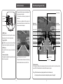
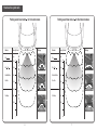
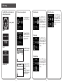
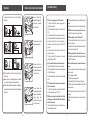
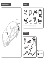
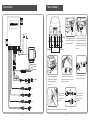
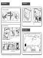
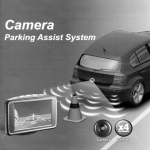
PTSV403
Camera
Parking Assist System
PTSV403 75545485
Camera
Sensor
Contents
Reasons to choose Steelmate
User's Manual
1. Professional manufacturer with high quality
standards.
Installation Manual
Reasons to choose Steelmate --------------------
1
Brief installation diagram -------------------------- 14
Disclaimer --------------------------------------------
1
Packing list ------------------------------------------- 15
Important notice -------------------------------------
2
Installation tools ------------------------------------ 15
Key features -----------------------------------------
2
Wire connection ------------------------------------- 16
About the product ----------------------------------
2
Sensor installation ---------------------------------- 17
Technical specifications ---------------------------
3
Camera installation -------------------------------------- 18
4. More than 100 engineers in the company, you
can enjoy the latest technology.
About the monitor ----------------------------------
3
ECU installation ------------------------------------------- 19
5. More than 300 patents.
Self-test function ------------------------------------
4
Monitor installation -------------------------------------- 19
About the parking assist lines --------------------
5
Parking assist lines mode selection and
How does the system work ------------------------
6
adjustment -------------------------------------------------- 20
Assist System
OSD setting ------------------------------------------
8
Function test after installation ----------------------- 21
User's Manual
2. Complete range of products, you can easily
select a product to match.
3. There are agents/distributors in more than 80
countries to supply local service.
6. Products have international approvals, high
quality guaranteed.
Camera Parking
7. Leading manufacturer in automotive industry,
ISO9001, ISO/TS16949, ISO14001 and
OHSAS18001 certified.
Attention ---------------------------------------------- 10
Sensor and camera maintenance ---------------- 10
Troubleshooting ------------------------------------- 11
Disclaimer
Warranty terms -------------------------------------- 12
Steelmate warranty card --------------------------- 12
The camera parking assist system is designed
as a driver assistance device, and should not be
used as a substitute for safe parking practices.
The area into which the vehicle is to be reversed
must be constantly visually monitored while
parking.
Steelmate and its distributors do not guarantee
or assume liability for collisions or damages while
reversing your vehicle.
1
Important notice
About the product
Technical specifications
Steelmate parking assist systems help to provide
assistance when reversing and parking. Driving skills,
such as slowing down, use of mirrors etc. are always
essential.
PTSV403 is a camera parking assist system with
parking assist lines shown on the TFT LCD monitor.
For parking assist system
Input voltage
10~16VDC
Operating current
<250mA
Detection range
0.1 ~ 2.5m
Display range
0.3 ~ 2.5m
Operating temperature
-40* ~ +85*
Turn ACC on and engage reverse gear, the system
will start scanning the rear area. If there is any
object within the detection range, the image, digital
distances and corresponding parking assist lines
will appear on the monitor while the audible sound
will change tones when the distance gets shorter
(voice warning is optional).
1. This unit is for vehicles with 12V DC only.
2. This unit should be installed by a professional auto
technician.
3. Route wiring harness away from heat sources
and electrical components.
4. It is strongly recommended to check the position
of the sensors before the actual drilling of the
holes.
5. Perform tests after finishing the installation.
Each piece of our products has passed the most
stringent test before releasing to the market. It
performs well at a wide temperature range and
becomes very useful when you are reversing at
a raining day, snowing day or at night etc. With
Steelmate's camera parking assist system on
board, you can enjoy a convenient and nervousfree
reversing experience.
Key features
TFT LCD monitor with parking assist lines
OSD menu
Flush mount or micro-tab camera available
Shock, vibration and water resistant camera
PAL or NTSC mode available
Accurate digital distance and clear rearview shown
on the monitor
Audible warning and voice warning (optional),
volume adjustable
Self-test function
Anti-false alert technology
For rearview camera
Video standard
Graphic sensor
Horizontal resolution
Minimum illumination
View angle
Operating temperature
For TFT monitor
Size
Resolution
System
Input voltage
Working current
Operating temperature
Beep volume
About the monitor
1. Rearview
on the LCD monitor
2.OSD parking
assist lines
3.Digital distance
NTSC / PAL
Color sensor
400 TV lines
<1.5 Lux
120 / 135 / 138
-20*~+80*/
-40*~+85*
(Front)
1. Rearview on the LCD monitor
The color camera automatically projects the image
behind the car to the monitor once the reverse gear
is engaged.
2. Parking assist lines
The space between the 2 vertical parking assist
lines is equivalent to the width of your vehicle. Any
object in that space will hinder your reversing.
The color distance indicator will appear on the monitor
when the vehicle is getting closer to the obstacle.
2.5''
640 (H) x 240 (V)
NTSC / PAL
9 ~ 16VDC
<250mA
-20* ~ +60*
70~90dB
3. Digital distance
Detection range: 0.3~2.5m.
The distance detected by the sensors will be shown
on the left and right side of the monitor. The digital
number on the monitor will be refreshed every 0.1m.
When the obstacle distance is less than 0.3m,"STOP"
will be shown on the monitor and the speaker will beep
continuously or say "STOP" (when the voice warning
is turned on).
* The technical specification of the camera
may vary. It may change according to the camera
design.
2
2.5m
3
Self-test function
The system will test the sensors automatically when
the reverse gear is selected.
1) If all sensors are functioning, the system will
beep once.
2) If there is any problem with the sensors, the
system will beep three times to indicate that one
or more sensors are damaged.
4. MENU button
5.
and
button
6. SET button
7. Universal joint base
(Rear)
4. MENU button
The MENU button is used to open the on-screendisplay menu and to return to pevious menu.
5.
and button
and button are used to select voice on/off and
to adjust volume, brightness, contrast, and color .
About the parking assist lines
The rear image
Right obstacle
distance indicator
Left obstacle
distance indicator
Green (2.59-1.6M)
Green (2.59-1.6M)
Yellow (1.59-1.2M)
Yellow (1.59-1.2M)
Yellow (1.19-0.9M)
Yellow (1.19-0.9M)
Red (0.89-0.6M)
Red (0.89-0.6M)
Red (0.59-0.3M)
Red (0.59-0.3M)
2.5m
6. SET button
Press the SET button to save and confirm the
selection.
7. Universal joint base
The display can be adjusted to any direction to meet
the driver's requirement.
Any damaged sensors should be replaced.
Obstacle distance
This picture indicates all sensors are functioning
and the obstacle distance is more than 2.59m.
Parking assist lines
Status preserving
All the previous settings (such as parking assist lines mode and color contrast etc.) will be saved after
power-off. No further adjustment is needed when the power is on again.
Note
4
All the distances shown by parking assist lines are for reference only.
For parking assist lines mode selection and adjustment, please refer to page 20.
5
How does the system work
Parking assist lines mode 1
Buzzer
for micro-tab camera
Parking assist lines mode 2
Display
Voice (Optional)
Stop
Be
Buzzer
Be
0.6m
Be-Be-Be-Be-
0.8m
Be--Be--
0.3m
STOP
Be
Be
0.6m
Be-Be-Be-Be-
0.8m
Be--Be--
1.2m
0.8m
1.5m
No Beep
Display
Voice (Optional)
Stop
Be
0.3m
Be
for flush mount camera
2.5m
1.2m
0.8m
1.5m
No Beep
2m
STOP
2m
2.5m
2.5m
2.5m
6
7
OSD setting
Once ACC is ON, one of the default clock
setting will appear as below
1. Volume and voice adjustment
2. Date & calendar
5. Turn off the display
DISPLAY OFF
INPUT
Press the MENU button
to enter the OSD menu.
VOLUME/VOICE
Press or button to
choose. Press SET
button to activate the
hightlighted option.
CALENDAR
(Factory default)
Press MENU and then
button to select
CALENDAR icon, then
press SET button to
enter CALENDAR
menu to change setting.
Mode 1
09/14/2009 MON
3. Time setting
TIME
17:00
Mode 2
VOLUME/VOICE
VOLUME
VOICE
17:00
09/14/2009
Press MENU and then
button to select TIME
icon, then press SET
button to change the
setting.
Press SET button again
to choose the volume.
SUN MON TUE WED THU FRI SAT
30
31
1
2
3
4
5
6
7
8
9 10 11 12
13
14 15
16 17 18 19
20
21 22
23 24 25 26
27
28 29
30
1
2
3
4. Display setting
SYSTEM
Calendar mode
VOLUME
1
2
3
4
8
Press or
button to
select the volume (1 low
4 high).
Press MENU and
button to select SYSTEM
icon, then press SET
button to change the
setting.
Press SET to save and
press MENU to return to
the previous menu.
9
Press the MENU and
button to select DISPLAY
OFF. Press SET to turn
off the display. Press any
button to turn on the
display.
Attention
Sensor and camera maintenance
False detection may occur in the following
situations:
Do not wash the
sensor/camera with
squirt gun or swab
them forcibly.
Please wash car with
lowpressure water.
Please melt the ice
with warm water when
the sensors/camera is
covered by ice.
After installation, please fully test the system
before use.
Heavy rain, dirty or damanged sensor or camera
may result in false warning occasionally.
Ensure that the self-test procedure is completed,
the camera and all sensors are functioning before
reversing.
Please clean the
sensors/camera with
cloth or low-pressure
water when the
sensors are covered
by mud or snow.
10
Troubleshooting
There is no image on the LCD monitor.
1) Check whether the power supply wire is
connected correctly.
2) Check whether the ignition is turned to ACC
ON.
3) Check whether the reverse gear is selected.
4) Check whether all the connections are correct.
5) Check whether the video output plug is
connected to the video-in socket of the LCD
monitor.
6) Check whether the function setting of the
monitor is correct.
7) Check whether the camera is correctly
connected to the ECU.
2) Check whether the sensor is installed up-sidedown.
3) Unplug 1 sensor at a time to check for response.
Audible voice or warning sound is too low.
1) Adjust the volume to a certain level.
Blurred image on the LCD monitor?
1) Check whether there is dirt or water on the
lens of the camera.
2) Clean the lens with a wet cotton swab and then
dry it with a soft clean cloth.
Parking assist lines is too high or too low.
1) Adjust the parking assist lines properly according
to P20 in the manual.
If the problem persists, please follow these
steps:
A. For consumers: contact your dealer or nearby
service center.
B. For installer or dealer:
1) Check the wire connection.
2) Replace the ECU and recheck the system
3) Test the sensors with certified ECU using a flat
wooden board.
4) Plug the certified sensors into the ECU and
recheck.
5) Email your questions to us and we will reply
ASAP.
The monitor indicates a defective sensor.
1) Check whether the sensor surface is clean.
2) Check whether the sensor wires are plugged
in the ECU properly.
3) Check whether the sensor wires are damaged
or not.
The object position does not correspond to
that on the monitor.
1) Are the sensor cables connected to the ECU
in the correct order e.g. A. B. C. D?
When reverse gear is selected, 0.5m ~ 0.6m
will be shown on the LCD monitor. (No obstacle
behind the vehicle)
1) Check whether sensors are mounted too low
or detecting the ground?
11
Warranty terms
b) Damage to the system caused by accident or
improper use in any manner whatsoever not the
fault of Steelmate, including but not limited to
damage by water or as a result of excess voltage
applied to the system or if misused or repaired or
altered in any way other than by Steelmate or it's
authorized agent.
c) False information displayed in the panel of the dash
board that is caused by car with CAN bus system.
I. The unit is warranted for a limited period of time
from the date of purchase. In the unlikely event
of a defect arising in this product when used in
accordance with the manufacturer's instructions,
the parts would be repaired or replaced free of
charge.
a) It is required to show warranty card when making
any warranty claims.
b) The model and the unit's serial number must
be the same as the information on the warranty
card.
Steelmate warranty card
II. This warranty is non-transferable and is
automatically void if:
a) The original purchaser has not completed the
warranty card.
b) The unit's serial number is defaced, missing or
altered.
c) The unit has been modified or used in not to
its intended purpose.
d) The unit has been damaged by accident,
unreasonable use, neglect, improper installation
or service.
Camera Parking
User:
Assist System
Tel:
Installation Manual
Vehicle Reg No.:
Product Model No.:
Serial No.:
Date of Installation:
III. The warranty does not cover:
a) Damage caused by incorrect or poor installation,
problems which may be caused by anomalies
in the vehicle's electrical system or originating
from the environment in which the system is
operated;
Name of the Retailer:
Signed by Retailer:
12
13
Packing list
Brief installation diagram
x4
x4
*
Sensor
D
C
Camera
B
* Camera
Hole saw
Power harness
Harness
* The actual sensor or camera may vary from the image shown above
A
ECU
LCD monitor
Installation tools
45' ~ 60'
14
15
Wire connection
Sensor installation
GND
A B C D
Red
Reversing light
45~70cm
12~20cm
1. Select a proper surface area
which is 45~70cm to the ground
as a horizontal guideline.
12~20cm
2. Select a smooth surface area
along the horizontal guideline, and
12~20cm away from the left and
right side. Mark them for A and D
sensors.
Black
(Pink) ACC
(Orange) DC
Equal
(Black) GND
Black
Red
Black
or
Flush mount camera
Micro - tab camera
3. Divide the distance between
sensor A and D into three parts.
Mark the average point for B
and C sensor.
4. Check the size of the hole saw to be
matching the diameter of the sensors
before drilling any holes.
up
5. Install the sensor vertically, the
"up" sign must be on upside.
Sensor D
Sensor C
Sensor B
7. Insert the plug into
the socket and turn
the sealing screw
cap tightly.
6. Install the sensor
into the hole and
mount firmly in the
bumper.
Sensor A
The sensor shown above may be different from the product.
16
17
Camera installation
ECU installation
Flush mount camera installation
Equal
Insert the
camera
and press
into the
hole firmly.
Camera
Mount ECU on the driver's side of the trunk.
Connect the red wire to the reversing light
wire (+).
Micro - tab camera installation
Monitor installation
1. Choose a proper place
above the number plate and
drill a hole.
2. Fix one side of the camera
with screw
2.5m
3. Fix the other side of the camera with screw
4. Connect the system to the monitor and adjust the
camera direction accordingly.
18
Before fixing the monitor on the dash board, adjust the brightness or contrast of the monitor if needed.
19
Parking assist lines mode selection and adjustment
The choice of parking assist lines
mode is based on the camera type.
Mode 1 is for micro-tab camera, while
mode 2 is for flush mount camera.
STOP
Mode 1
STOP
The width of rear view image is
suggested to be the same as the
width of the vehicle.
Function test after installation
1 3 5
2 4 R
Mode 2
Parking assist lines adjustment
a. Select the reverse gear
b. Press and hold the MENU button to
enter the parking assist lines mode
c. Select mode 1 or mode 2 with or
button
d. Press SET button once to confirm
the selection.
e. Press or
button to adjust the
width of parking assist lines. Press
SET button to confirm the selection.
2.59m
Use a flat board (1.0x1.5m) standing behind the car, reverse slowly to test each function respetively as
shown in the manual.
20
21