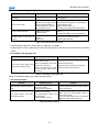
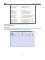
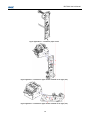
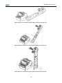
1
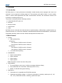
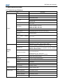
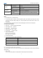
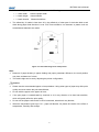
User’s Manual Kiosk Printer BK-T680 Shandong New Beiyang Information Technology Co., Ltd BK-T680 User’s Manual Declaration Information in this document is subject to change without notice. SHANDONG NEW BEIYANG INFORMATION TECHNOLOGY CO., LTD. (hereinafter referred to as “SNBC”) reserves the right to improve products as new technology, components, software, and hardware become available. If users need further data about these products, please feel free to contact SNBC or your local dealer. No part of this document may be reproduced or transmitted in any form or by any means for any purpose without the express written permission of SNBC. Copyright Copyright © 2011 by SNBC Printed in China Version 1.0 Trademark Registered trademark of SNBC: Warning and caution Warning: Items shall be strictly followed to avoid injury or damage to body and equipment. Caution: Items with important information and prompts for operating the printer. SNBC has been approved by the following certifications: ISO9001 Quality Control System ISO14001 Environmental Management System OHSAS18001 Occupational Health and Safety Management System IECQ QC080000 Hazardous Substance Process Management System -1- BK-T680 User’s Manual Safety instructions Before installing and using the printer, please read the following items carefully: 1. Safety warning Warning Warning Do not touch the cutter of the printer. The print head is a thermal element and it is at a high temperature during printing or just after operation, therefore do not touch it or its peripherals for reasons of safety. Warning The print head is an ESD-sensitive device. To avoid damage, do not touch either its printing parts or connecting parts. 2. Cautions 1) Install the printer on a flat and stable surface; 2) Reserve adequate space around the printer so that convenient operation and maintenance can be performed; 3) Keep the printer far away from water source, and do not expose the printer to direct sunlight, strong light and heat; 4) Do not use or store the printer in a place exposed to high temperature, high humidity or serious pollution; 5) Do not place the printer in a place exposed to vibration or impact; 6) No condensation is allowed to the printer. In case of such condensation, do not turn on the power until it has completely gone away; 7) Connect the printer power to an appropriate grounding outlet. Avoid sharing one electrical outlet with large power motors or other devices that may cause the fluctuation of voltage; 8) Disconnect the power when the printer is deemed to idle for a long time; 9) Don’t spill water or other electric materials into the printer (e.g. metal). In case this happens, turn off the power immediately; 10) Do not allow the printer to start printing when there is no recording paper installed; otherwise the print head and platen roller will be damaged; 11) To ensure quality print and normal lifetime, use recommended paper or its equivalent; 12) Shut down the printer when connecting or disconnecting interfaces to avoid damages to control board; 13) Set the print darkness to a lower grade as long as the print quality is acceptable. This will help to keep the print head durable; 14) Do not disassemble the printer without permission of a technician, even for repairing purpose; 15) Keep this manual safe and at hand for reference purpose. -2- BK-T680 User’s Manual Content 1 Overview.............................................................................................................................................. 1 1.1 Introduction .................................................................................................................................... 1 1.2 Main features ................................................................................................................................. 1 2 Main technical index........................................................................................................................... 3 2.1 Technical specifications ................................................................................................................. 3 2.2 Paper specifications ....................................................................................................................... 4 3 Structures and functions ................................................................................................................... 6 3.1 Appearance.................................................................................................................................... 6 3.2 Overall size .................................................................................................................................... 6 3.3 Print module and controlling parts.................................................................................................. 7 3.4 Presenter ....................................................................................................................................... 9 4 Installation and suggestion ............................................................................................................. 11 4.1 Unpacking .................................................................................................................................... 11 4.2 Adjusting paper guide .................................................................................................................. 11 4.3 Adjusting mark sensor.................................................................................................................. 11 4.4 Grounding .................................................................................................................................... 12 4.5 Connecting power adapter ........................................................................................................... 13 4.6 Connecting interface cable........................................................................................................... 14 4.7 Installing paper roll and loading paper ......................................................................................... 14 4.8 Installing printer............................................................................................................................ 15 4.9 Installing printer driver.................................................................................................................. 17 5 Routine maintenances...................................................................................................................... 21 5.1 Cleaning mark sensor .................................................................................................................. 21 5.2 Cleaning print head and platen roller ........................................................................................... 22 5.3 Cleaning paper out sensor ........................................................................................................... 23 5.4 Cleaning retraction sensor ........................................................................................................... 24 5.5 Clearing jammed paper in the cutter ............................................................................................ 25 5.6 Clearing jammed paper in the presenter ...................................................................................... 25 6 Interface signal ................................................................................................................................. 26 -3- BK-T680 User’s Manual 6.1 RS-232 interface .......................................................................................................................... 26 6.2 USB interface ............................................................................................................................... 27 6.3 Parallel interface .......................................................................................................................... 27 6.4 Ethernet interface......................................................................................................................... 29 6.5 Power interface ............................................................................................................................ 29 7 Troubleshooting and maintenance ................................................................................................. 31 7.1 Error type and settlement............................................................................................................. 31 7.2 Solution for common errors .......................................................................................................... 31 Appendix ............................................................................................................................................... 33 Appendix 1 Self-test page................................................................................................................... 33 Appendix 2 Software Tools ................................................................................................................. 36 Appendix 3 Optional parts................................................................................................................... 37 -4- BK-T680 User’s Manual 1 Overview 1.1 Introduction BK-T680 printer is a high performance embedded 2-sided thermal printer equipped with cutter and presenter, it can accept up to 300mm paper roll. The maximum print width is 80mm. It can be widely used in various Kiosk applications like data communication terminal, test instrument terminal and information consulting terminal, etc. The printer is configured with the following modules: ¾ 2-sided thermal (2ST) print unit ¾ Presenter ¾ Anti-jam module ¾ Control board ¾ Cutter BK-T680 can be connected with other devices via serial interface, USB interface, parallel interface or Ethernet interface, etc. Drivers are available for WINDOWS2000/XP/2003/Vista/2008/Win7, WindowsXP Embedded operating systems and the software development kit based on DLL. 1.2 Main features ¾ Printing High-speed printing 1ST printing: Print speed of 203DPI model is 275mm/s; Print speed of 305DPI model is 180mm/s. 2ST printing: Print speed of 203DPI model is 150mm/s; Print speed of 305DPI model is 100mm/s. ¾ Low-noise thermal printing PRESENTER Paper accommodation Paper retraction Paper holding Paper ejection Note: Presenter is at the front end of the printer. ¾ ¾ High reliability The cutter lifetime can be up to 1 million cuts (paper thickness: 65μm); Print head lifetime is no less than 100km (duty ratio 12.5%); MCBF: 37,000,000 lines (paper feeding) Applications Command set is compatible with ESC/POS standard; Characters processing: enlarge 1 to 6 times horizontally or vertically, rotation print (0°, 90°, 180°, 270°), black/white reverse, underline, upside-down print; 1 BK-T680 User’s Manual Barcode print: print barcode by commands in horizontal and vertical directions; Character size (Font A or Font B) can be selected by commands; ¾ Printer maintenance Replace paper roll easily; Clean the print head conveniently Characteristics and parameters can be set by software; Cut paper automatically; Semi-auto paper loading; Mark identification and calibration; Printer firmware on-line update. 2 BK-T680 User’s Manual 2 Main technical index 2.1 Technical specifications Item Parameter Print method Thermal Resolution 203/305DPI Paper width 48~82.5±0.5 mm Max.80mm (3.2 ") Print width Max.640 dots Max: 450 mm Min: 70 mm 200DPI 1ST (Max): 275 mm/s 200DPI 2ST(Max): 150 mm/s 300DPI 1ST (Max): 180 mm/s 300DPI 2ST (Max): 100 mm/s Print height Print speed Printing RAM memory SDRAM: 8 MB Flash memory 2MB/4MB (depends on the size of font library) Print head temperature detection Print head position detection Barcode Character Image Thermal resistor Micro switch Paper/mark detection Photoelectric/Mechanical photoelectric sensor Paper near end detection Photoelectric sensor Communication interface USB, RS-232 (optional) Barcode CODE128, ITF , UPC-A, UPC-E, EAN13, EAN8 CODE39, CODE93, CODABAR, PDF417, GS1, QR Character set Standard characters, compressed characters Optional Asian character set (simplified Chinese, traditional Chinese, Japanese, Korea) All characters can be enlarged 1 to 6 times vertical and Character processing Image horizontal respectively. Rotation print (0°, 90°, 180°, 270°); Emphasized, white/black reverse, underline. BMP bitmap can be downloaded to RAM and FLASH; Support direct bitmap printing Paper type Continuous paper/marked paper Paper roll OD Max.300mm Core ID ф18-60mm Paper thickness 60~150 um Thermal layer Outward / Inward Power consumption +24V power supply, at room temperature, average value 1.9A(12.5% duty ratio) PRESENTER Paper out detection Photoelectric sensor Paper out speed 1000mm/s Retraction detection Photoelectric sensor Retraction speed 1000mm/s Media 3 BK-T680 User’s Manual Reliability Environmental requirements Physical features Paper out mode Retraction/ holding /closing/ejection (optional) Print head lifetime ≥100Km Cutter lifetime ≥1, 000, 000(65μm thick thermal paper) MTBF 360,000 hours Operating environment 0~50℃, 20~90%RH(40℃) Storage environment -40~60℃, 20~93% RH(40℃) Overall size 161(L) X 123.2(W) X 120.9(H) (excluding paper holder, paper roll, including control board) Weight About 2.1Kg (excluding paper roll) Table 2.1-1technical specifications Notes: DPI: dots per inch. (1 inch≈25.4 mm); The real print speed is related to data transmission speed, print darkness, print duty ratio, control commands and power supply voltage, etc. The print speed may be lower than the value in the above table. PRESENTER is a mechanism used to accommodate paper at the front end of the printer. 2.2 Paper specifications ¾ Paper type: continuous paper/marked paper ¾ Paper supply mode: ¾ Paper width: ¾ Paper thickness: 60um~150um ¾ Thermal layer: ¾ Paper roll specifications: paper roll 48~82.5±0.5 mm outward / inward Optional core ID: ф18-60mm Max. paper roll OD: ф300mm ¾ Recommended paper: 1) Recommended continuous paper specifications: Paper model Manufacturer TF50KS-E2C Nippon Paper Industries Co., Ltd F240AC/F220-VP Mitsubishi Paper Mill CO., LTD KF060-FEAH NEW OJI Paper CO., LTD. F70NA FUJI PHOTO FILM CO., LTD FV230A1 MITSUBISHI PAPER MILL CO., LTD. Table 2.2-1 Recommended paper 2) Recommended marked paper specifications: The marked paper should not only meet the requirements for standard paper, but also meet the following requirements: Mark position User can select the position of mark (located on thermal layer/non-thermal layer); 4 BK-T680 User’s Manual When selecting mark, it is recommended to use the following parameters: 9 L1 mark width: 8mm≤L1≤paper width 9 L2 mark height: 4mm≤L2≤8mm 9 L3 mark interval: 58mm≤L2≤305mm The reflectivity of marks is less than 10%; the reflectivity of other part of the ticket within mark width along paper feed direction is over 75%.There should be no character or pattern such as advertisement between two marks. Figure 2.2-1 Schematic diagram of mark position Note: Because of paper shaking in paper feeding and paper parameter difference, the mark position may have a tolerance of ±1mm; The mark height can be set by adjusting the printer configuration; Caution: Please use the recommended paper or its equivalents. Using other types of paper may affect print quality and even reduce the print head lifetime; Do not stick the paper to the paper roll core; If the print paper is contaminated by chemical or oil, it may discolor or be less heat sensitive, which will greatly affect the print quality; Do not rub the paper surface with a nail or hard metal, otherwise it may discolor; When the temperature goes up to 70℃, paper will discolor. So please be careful of the effect of temperature, humidity and sunlight. 5 BK-T680 User’s Manual 3 Structures and functions 3.1 Appearance Figure 3.1-1 BK-T680 printer appearance 1 —paper guide 2 —button 3 —print module 4 —cutter 5 —top cover locking axis 6 —Presenter 7 —LED paper outlet mouth 8 —paper near end sensor socket 9 —power interface 10 —USB interface 11 —serial interface 3.2 Overall size 6 BK-T680 User’s Manual Figure 3.2-1 Overall size of the printer with presenter Figure 3.2-2 Overall size of the printer with presenter and anti-jam module Note: The overall size of the printer only with anti-jam module is the same as that of figure 3.2-1. 3.3 Print module and controlling parts The controlling parts include circuit board and the corresponding adjustment buttons, interfaces, etc. 3.3.1 Appearance of print module and controlling parts Print module mainly consists of print mechanism, paper cutting mechanism, etc. Please refer to figure 3.3-1 for details: 7 BK-T680 User’s Manual Figure 3.3-1 Appearance of print module and controlling parts 1 —paper guide 2 —POWER LED 3 —ERROR LED 4 —PAPER LED 5 —RESET button 6 —FEED button 7 —CUT button 8 —cutter 9 —top cover locking axis 10 —power socket 11 —USB interface 12 —serial interface 3.3.2 Print module description ¾ Top cover locking axis Press the top cover locking axis slightly to separate the print platen roller from print head so as to clear some errors. ¾ CUTTON button Press this button to cut paper in any status (no matter the printer alarms or not). ¾ FEED button If the printer doesn’t alarm, press down this button to feed paper; Press this button continuously to feed long distance; Pressing and holding the FEED button while powering on the printer for one second, the printer will start and print a self-test page, the printout of which depends on the printer configuration. Note: Make sure that there is paper in the printer and the print head is not uplifted before starting self-test (for self-test page, please refer to Appendix 1 Self-test page) ¾ RESET button When pressing down this button, the printer will execute its reset and the print data will be cleared ¾ CUT button Press this button to cut paper in any status (no matter the printer alarms or not). ¾ PAPER LED (red) When paper end or paper near end is detected, PAPER LED will be always on; if the paper is in normal status, PAPER LED will not be on. ¾ ERROR LED (red) Indicate different status of the printer. Normally, ERROR LED is not on; when errors occur (for 8 BK-T680 User’s Manual example, paper end), ERROR LED will flash to give alarms. Note: ERROR LED flashes when the printer is executing macro definition. ¾ POWER LED (green) Indicate whether the power is on or not, and it is always on when the power is turned on. Heating: Print head: The print head and motor generates heat in use; please do not touch them just after operation. 3.4 Presenter Figure 3.4-1 Presenter appearance 1. Presenter upper path 2. Presenter floating roller 3. LED paper outlet mouth 4. Paper near end sensor socket 9 BK-T680 User’s Manual 5. Presenter turning board 6. Presenter drive roller 7. Paper out sensor: to detect paper status and determine whether it is taken away or not. 8. Retraction sensor: to detect whether paper is retracted correctly or not in the paper retraction process. 10 BK-T680 User’s Manual 4 Installation and suggestion 4.1 Unpacking Open the carton and check whether all items listed on the packing list are included or have any damages. In case of damages or missing items, please contact your dealer or the manufacture for assistance. 4.2 Adjusting paper guide Open the carton and adjust the paper guide to meet different paper width before installing printer. BK-T680 can use paper adjustable from 48 to 82.5mm. Adjust the paper guide to right position as showed in the following figure. Three are six scale marks on bottom cover of paper guide: 82.5mm, 80 mm, 76 mm, 70 mm, 56 mm, 48mm. Remove the paper guide to adjust the gap be aligned with the dot of target scale mark. Figure 4.2-1 Adjusting paper guide Note: Unscrew the screws that fix the paper guide in anticlockwise direction before removing the paper guide, and then tighten the screws after the paper guide reaching the right position. Figure 4.2-2 Adjust the paper guide fixing screws 4.3 Adjusting mark sensor The position of mark sensor on BK-T680 printer can be adjusted to right or left side, thermal or non-thermal side. The mark sensor needs to be adjusted when following cases occur: 11 BK-T680 User’s Manual The position of mark on paper is inconsistent with the position of mark sensor (including right/left side, thermal/non-thermal side). Steps to adjust the position of mark sensor to right/left side: 1) Rotate the cross screw driver deep in the printer in the direction shown in the figure 4.3-1 to adjust the position of mark sensor; Figure 4.3-1 Adjusting mark sensor 2) The bulge that aligns with scale mark indicates the corresponding mark sensor position, as shown in the figure 4.3-2. Take out the cross screw driver when the sensor get to the right position; Figure 4.3-2 Adjusting mark sensor Steps to adjust the position of mark sensor to thermal/non-thermal side: 1) Refer to step 1 in “5.1 cleaning mark sensor” to remove the paper guide module; 2) Refer to step 2 in “cleaning mark sensor” to remove the screw module of mark sensor, and exchange the upper and the lower screw modules of mark sensor, then the position of mark sensor (thermal/non-thermal side) is changed. 4.4 Grounding To ensure the printer is well grounded, connect the grounding cable as showed in the figure 4.3-1. Necessary tools: cross screw driver. Fix the grounding cable to one of the fixing holes (11 pcs of M3 holes) shown in figure 4.4-1 when installing the printer, and complete the connection of grounding cable. Note: The screw length is 4mm. 12 BK-T680 User’s Manual Figure 4.4-1 Grounding place 4.5 Connecting power adapter 1) Ensure the printer power is turned off; 2) Insert the power adapter cable into the power interface at the bottom of the printer as showing in figure 4.5-1. Figure 4.5-1 Connecting power adapter 3) Connect the input power supply of power adapter. Caution: Use the recommended power adapter or the equalities. Connect power adapter connector at a right angle between pin and socket; When connecting or disconnecting the cable connector of power adapter, always hold the connecter shell and don’t pull the cable forcibly. Avoid dragging or pulling the cable of AC adapter, otherwise the cable may be damaged or broken, and a fire and electric shocking may be caused accordingly. Avoid placing the power adapter near an overheating device, otherwise the surface of cable may melt and cause a fire or electric shock. If leaving the printer idle for a long time, please disconnect the power adapter of printer. 13 BK-T680 User’s Manual 4.6 Connecting interface cable 1) Make sure that the printer has been shut down, (sign “O” in power switch is pressed down); 2) Connect the interface cable to the corresponding interface (refer to figure 4.6-1); 3) Connect the other end of the cable to PC. Figure 4.6-1 Connecting interface cable Caution: Make sure the interface cable is connected in correct direction. When connect or disconnect the interface cable, make sure to hold the plug shell instead of dragging the cable forcibly. 4.7 Installing paper roll and loading paper Before starting to load the paper roll, make sure the specification of paper roll is conformity with printer requirements (refer to 2.2 Paper specification). 4.7.1 Steps for installing paper roll The paper roll installation of BK-T680 is quite easy, detail operations are as following: 1) Turn on power and place the paper head into the paper feeding path as shown in figure 4.7-1: Figure 4.7-1 Paper loading 2) Roller starts rotating when paper sensor detects paper presence to finish semi-automatic paper feeding. Note: Before loading paper, cut the paper head trimly as showed in the following figure. Figure 4.7-2 Paper head 14 BK-T680 User’s Manual 4.7.2 Semi-automatic paper loading 1) Turn on the power and the LED flashes for alarming paper end; 2) Refer to figure 4.7-1, push the paper into paper inlet slightly for a certain distance, and release the hand when the platen roller starts to rotate and hold the paper; 3) Printer starts to feed paper and is possible to print when paper head stops at the normal printing position after printer stops feeding paper. Caution: When push the paper into the feeding path, the strength should be well-distributed and gentle, try to make the front head of the paper parallel to the feeding paper path to avoid the paper decline. 4.8 Installing printer BK-T680 embedded printer is a printer with easy and reliable operation, and it has good adaptability of installing and good maintenance. It adapts modularization design, active connection, flexible maintenance and operation station according to the embedded characters. Please refer to the content of this section when design the whole machine that the printer will be used for, to ensure the reliable and effective work of BK-T680 embedded printer. 4.8.1 Installation notice ¾ Install the printer on a flat and stable place. Recommend to use horizontal installation, the inclination angle shouldn’t exceed ±15° (paper feeding direction). Inclination in other directions is strictly forbidden; ¾ the flatness of fixed surface should equal and less than 0.3mm; ¾ Keep the printer far away from water source. ¾ Do not place the printer in the place exposed to vibration and impact. ¾ Ground the printer safely; 4.8.2 Fixing printer Figure 4.8-1 Fixing printer ¾ The printer fixing hole position please refer to figure 3.2-1 and figure 3.2-2 ; ¾ Screw length (H) ≤ bottom board thickness (h) + 6mm. For example, when the thickness of bottom board is 4mm, the length of screw should not exceed 10mm. 15 BK-T680 User’s Manual 4.8.3 Operation space ¾ Open the top cover: push forward the open cover shaft to open the top cover as shown in the figure; Figure 4.8-2 Printer space with standard paper holder ¾ Retraction space: Space to collect the receipt not taken away by customer. Figure 4.8-3 PRESENTER space ¾ PRESENTER space:PRESENTER space is inside the printer and its acceptable maximum length of receipt is 170mm. If the length of receipt exceeds 170mm, space needs to be reserved at the bottom of printer. Height of reserved space (H) ≥ (receipt length – 170mm) / 2. 16 BK-T680 User’s Manual 4.9 Installing printer driver BK-T680 printer provides driver for operation system as Windows 2000/ Windows XP/ Windows server 2003/Windows Vista/Windows Server 2008/Windows 7, and the installation includes typical installation and advanced installation. 4.9.1 Typical installation Steps for typical installation are as following: 1) Run " Setup_BK-T680_EN V1.0\Setup.exe". Please read the legal agreement carefully. If you agree to the terms of this agreement, click on the "I Accept" button, and then click on "Next" button. 2) Select install module and the name of the printer that will be installed. If you want to set the current printer as the default printer, select "Set As Default Printer", and then click on "Next" button. 3) Select the setup type "Typical", and then click on "Next" button. 17 BK-T680 User’s Manual 4) Select the current system, and then click on "Next" button. (Not support windows 2000 in 64bit OS) 5) Set printer port, select port "LPT1" as printer port, and then click on "Install" button to start the installation. 4.9.2 Advanced installation Advanced installation is mainly used for the users who have special requests to the printer driver. Different to typical installation, it supports driver for printer with several USB ports and has the function to 18 BK-T680 User’s Manual set printer driving mode. Steps for advanced installation are as following: 1) Run " Setup_BK-T680_EN V1.0\Setup.exe". Please read the legal agreement carefully. If you agree to the terms of this agreement, click on the "I Accept" button, and then click on "Next" button. 2) Select install module and the name of the printer that will be installed. If you want to set the current printer as the default printer, click on "Set As Default Printer", and then click on "Next" button. 3) Select the setup type: "Advanced", then click on "Next" button. 19 BK-T680 User’s Manual 4) Select the current system, and then click on "Next" button. ( Not support windows 2000 in 64bit OS ). 5) Select printer port. The default print port is "LPT1". If the port is USB port, you can install Multi-USB printers. Click "Install" to start the installation. 20 BK-T680 User’s Manual 5 Routine maintenance Caution: Before starting routine maintenance for the printer, make sure the power is turned off. Do not touch the surface of print head with hands or metal. Do not use forceps so as to prevent print head, platen roller and sensors being scratched. Do not use organic solvent like gasoline, acetone and etc. When cleaning print head or sensors, please wait for pure alcohol to evaporate totally before starting printing. It is recommended to do routine maintenance per month. 5.1 Cleaning mark sensor When the following cases occur, the ,mark sensor should be cleaned: ¾ The printer doesn’t identify marks correctly. Cleaning steps for mark sensor: 1) Slightly nip the latches on both sides of paper guide cover and pull outward the top of paper guide cover to remove the paper guide module. Figure 5.1-1 Cleaning mark sensor Caution: The cable of sensor on paper guide module is connected with main control board, thus do not remove the paper guide module by force. Pull out the cable of sensor from the main control board after slowing opening the paper guide module as the above method. 2) Remove the thumb wheel shown in figure 5.1-2, and then remove the screw where the mark sensor is installed (refer to figure 5.1-2) and wipe off the dust or stains on the sensor surface with soft cotton cloth dipped with pure alcohol (it should be wrung out). Wait for 5 to 10 minutes until pure alcohol evaporates completely, and then assemble it in the reverse steps. Check the cable 21 BK-T680 User’s Manual connection after completing the assembly, and turn on the power if the cable is correctly connected. Figure 5.1-2 Cleaning mark sensor 5.2 Cleaning print head and platen roller When the following cases occur, the print head and platen roller should be cleaned; ¾ Printout is not clear; ¾ Some columns on the page are not clear; ¾ Paper feeds or retracts with big noises. Cleaning steps for print head and platen roller: 1) Turn off the printer power; 2) Slightly press the lock axis of top cover in the direction shown in the figure 5.2-1 to open the top cover module; Figure 5.2-1 Cleaning print head 3) In figure 5.2-2, No.1 is platen roller and No.2 is print head. Clean the surface of print head with soft cotton cloth dipped with pure alcohol (it should be wrung out); 22 BK-T680 User’s Manual Figure 5.2-2 Cleaning print head 4) Wipe off dust and stains on the surface of the platen roller with soft cotton cloth dipped with neutral detergent (it should be wrung out); 5) Execute the assembly according to the reverse steps after the print head and platen roller are dry, and then check the connecting cable and turn on the power after ensuring the correct connection. 5.3 Cleaning paper out sensor When any of the following case occurs, paper out sensor should be cleaned; The paper can’t back to normal printing position during semi-automatic paper load; Motor for printing reverses backward for long time during semi-automatic paper load; PRESENTER can not hold paper normally; Not execute paper retraction after PRESENTER holding paper; Cleaning steps for paper out sensor: 1) Turn off the printer power; 2) Slightly press down the clock axis of top cover in the direction shown in the figure 5.2-1 to open the top cover module; 3) Slightly press the latch on Presenter upper path in the direction shown in the figure 5.3-1, remove the Presenter upper path module, then the dustproof cover of paper out sensor located on Presenter path can be seen. Wipe off dust and stains on the surface of the dustproof cover with soft cotton cloth dipped with pure alcohol (it should be wrung out); 23 BK-T680 User’s Manual Figure 5.3-1 Cleaning paper out sensor 4) Wait for 5 to 10 minutes until pure alcohol evaporates completely, and then install the Presenter upper path module and turn on power. 5.4 Cleaning retraction sensor When any of the following case occurs, retraction sensor should be cleaned; ¾ Presenter fails to transmit paper retraction information properly. Cleaning steps for retraction sensor: 1) Turn off the power; 2) Shown as in Fig.5.4-1, you can view the retraction sensor at the retraction path of PRESENTER. Wipe off dust and stains on the sensor surface with soft cotton cloth dipped with pure alcohol (it should be wrung out); Figure 5.4-1 Cleaning retraction sensor 3) Wait for 5 to 10 minutes until pure alcohol evaporates completely, and turn on the power. 24 BK-T680 User’s Manual 5.5 Clearing jammed paper in the cutter When any of the following errors occurs, please remove jammed paper manually; ¾ Paper jams between platen roller and cutter; ¾ Paper accumulates at paper inlet of the cutter in the front of print head. ¾ The cutter can’t cut off paper. Remove jammed paper in the following steps: 1) Turn off the power; 2) Refer to steps 2 in “5.2 Cleaning print head and platen roller”, slightly press down the lock axis of top cover in the direction shown in figure 5.2-1, and open the top cover module; 3) Check whether there is any wastepaper under the cutter blade and print head. If so, please take it out; 4) Close the top cover if there is no wastepaper; Caution: Turn off the power before you remove the jammed paper. 5.6 Clearing jammed paper in the presenter When any of the following errors occurs, please remove the paper manually: ¾ Paper is jammed into the path of presenter; ¾ Paper does not enter into paper out path of presenter; Remove jammed paper in the following steps: 1) Refer to step 3 in “5.3 Cleaning paper out sensor”, slightly press down the latch on Presenter upper path in the direction shown in figure 5.3-1, and then remove Presenter upper path module; 2) Remove the jammed paper. 25 BK-T680 User’s Manual 6 Interface signal 6.1 RS-232 interface 6.1.1 Parameter Data transfer mode: asynchronous serial communication Handshake mode: RTS/CTS control Voltage level: MARK = -3 to -15 V: Logic "1"/ OFF SPACE = +3 to +15 V: Logic "0"/ ON Baud rate: 1200, 2400, 4800, 9600, 19200, 38400, 57600 bps Data bit: 8 bit or 7 bit Parity checkout: None, even, or odd Stop bit: 1 bit Connector: 9 pins serial connector (negative head) Note: Serial baud rate, data bit, parity bit are set by EEPROM 6.1.2 Interface linking terminal distribution and signal function Printer signal and status is described as the following table: No. Signal name Signal direction Function 1 NC — Not connected 2 TXD Output Transmit data 3 RXD Input Receive data 4 DSR Input Data set ready 5 GND — Signal ground 6 DTR Output Data terminal ready 7 CTS Input Clear to send 8 RTS Output Request to send 9 NC — Table 6.1-1 Interface and pin explanation 6.1.3 Demonstration of interface connection Host side Printer side TXD---------------RXD RXD---------------TXD DSR---------------DTR CTS---------------RTS RTS---------------CTS DTR---------------DSR GND---------------GND Note: Please make sure the printer is turned on and wait for the end of initialization, then send data to the printer. 26 BK-T680 User’s Manual 6.2 USB interface USB interface is the standard interface of the printer, which meets USB 2.0 protocol standard, and work in full speed mode. Data transfer bit rate is 12Mbps. 6.2.1 Interface specification Data transmission: Support USB 2.0 protocol Connector (printer end): USB B series socket. Support and connect through USB HUB 6.2.2 Interface definition and functions Pin No. Signal name Description 1 VBUS +5V 2 DATA- Data transmission negative end 3 DATA+ Data transmission positive end 4 GND Grounding Table 6.2-1 USB interface signal definition 6.2.3 Demonstration of USB interface connection Host side Printer side VBUS ..................................…VBUS DATA-................................…. DATADATA+................................... DATA+ GND .................................... GND 6.2.4 Interface connector Figure 6.2-1 USB interface connector 6.3 Parallel interface 6.3.1 Parameter Support IEEE1284 byte mode; Handshake mode: Busy signal; Signal voltage level: TTL; 6.3.2 Interface linking terminal distribution and signal function Printer signal and status is described as the following table: Pin Source Compatible mode 1 H nStrobe 2 Signal Ground 27 BK-T680 User’s Manual Pin Source Compatible mode 3 H Data 0 4 5 Signal Ground H Data 1 6 Signal Ground 7 H Data 2 8 H nSelectIn 9 H Data 3 10 Signal Ground 11 H Data 4 12 P Peripheral Logic High 13 H Data 5 14 Signal Ground 15 H Data 6 16 P nFault 17 H Data 7 18 Signal Ground 19 P nAck 20 H nAutoFd 21 P Busy 22 Signal Ground 23 P Perror 24 H nInit 25 P Select 26 Signal Ground Table 6.3-1 Pin list of interface module 6.3.3 Demonstration of interface connection Interface connector: IDC26 (CH2.54) socket; Use special parallel interface connecting wire with one end connecting with printer and the other end connecting with standard parallel interface communication cable (DB25M to CN36M). The standard parallel interface communication cable is connected with PC. 28 BK-T680 User’s Manual 6.4 Ethernet interface 6.4.1 Parameter ¾ Support 10BASE-T/100BASE-TX communication ¾ Compatible with Ethernet II standard frame type ¾ Indicator shows network connecting status and data transmission status ¾ Support 9100 port print ¾ Support status back ¾ Support parameter configuration ¾ Support firmware update on-line ¾ Support HTTP service, configure printer and detect status via embedded web page. 6.4.2 Interface linking terminal distribution and signal function Interface adopts 10BASE-T/100BASE-TX standard in accordance with IEEE 802.3/802.3u. The interface signal is defined as below: PIN Signal Name Instruction 1 TX+ Data transmission + 2 TX- Data transmission - 3 RX+ Data receiving + 4 NC Reserve 5 NC Reserve 6 RX- Data receiving - 7 NC Reserve 8 NC Reserve Table 6.1-1 Pin list of interface module 6.4.3 Interface connector Figure 6.4-1 Socket of interface module 6.5 Power interface Power connector is used to connect printer and external power supply device. 6.5.1 Pin distribution Reference connector type: molex/39-01-2020 Reference socket type: molex/39-30-7025 29 BK-T680 User’s Manual Figure 6.5-1 Power socket and connector Pin definition of power interface: Pin Signal definition Cable color 1 +24V Red 2 GND Black Table 6.5-2 Pin list of power interface 6.5.2 Power supply requirements Voltage supplied: +24 VDC ±10% Average current (24V, room temperature, 12.5% duty ratio sample): 2.5A 30 BK-T680 User’s Manual 7 Troubleshooting and maintenance In case of printer fault, consult this section for solutions and advice. If you do not find a solution in this section, please contact your local dealer for assistance. 7.1 Error type and settlement Display mode of error LED Error Description Recovery Print head overheating Temperature of print head is too high. Automatic recovery after temperature falling down. Print head uplifting Print head is uplifted. Automatic recovery after putting down the print head. Paper end Paper sensor detects paper end. Automatic recovery after reloading paper. Cutter error or paper jam Paper jams or cutter can’t work normally. Remove the jammed paper and press CUT button to cut paper. Table 7.1-1 Error index Note: Under printer default configuration, printer will not stop printing when paper near end, and user could change the printer configuration as stop printing when paper near end via KIOSKUtility software. Printer executes the follows activities when errors occur: ¾ Stop printing; ¾ Busy signal is available; ¾ Error LED flashes; 7.2 Solution for common errors 7.2.1 Problems during paper loading Problem Possible reasons Paper roll can’t be loaded into paper holder The core ID of paper roll does not match the printer. Paper head is irregular; paper jams; The paper out sensor is not covered by paper head; Dust and wastepaper covers the Paper out sensor. The printer can’t feed paper automatically Paper not stops at the normal printing position after automatically paper feeding Dust or wastepaper covers the paper out sensor Solution Replace paper. Dispose the paper head as requirements; Remove jammed paper; Check the front head of paper to confirm that the paper out sensor is covered fully; Clean the paper out sensor. Clean the paper out sensor. Table 7.2-1 Problems during paper loading 31 BK-T680 User’s Manual 7.2.2 Problems during printing Problems Possible reasons The receipt can’t be ejected out smoothly. Paper jams Printout is not clear The paper is loaded in wrong direction or its quality is poor; Print head needs cleaning; Printing darkness is too low; Input voltage is too low. Cutter works abnormally Paper jams in cutter; Cutter is broken Printing data is lost and no printing The top cover module is not closed; Paper jams. Solution Check paper path, remove wastepaper and reload paper. Make sure the paper roll is loaded correctly; Use recommended paper or its equivalents; Clean the print head; Adjust print darkness(*); Use the power supply that meets requires. Check if there are sundries in cutter path(*); Contact with SNBC or your local distributor. Close top cover module properly; Remove jammed paper. Table 7.2-2 Problems during printing *To adjust print darkness, contact with our distributors or SNBC; *If paper jams in cutter, please remove the jammed paper first, and then press CUT button to reset the cutter. 7.2.3 Problems during paper out Problems Possible reasons The printer stops printing and warns errors during printing. Paper is end; Paper jams in cutter; Dust or wastepaper covers the paper near end sensor; Paper near end (Printer is set to stop printing when paper near end). Solution Install a new paper roll; Check if there are sundries in cutter path; Clean the paper near end sensor. Table 7.2-3 Problems during paper out Note: Contaminated paper may cause detection failure. 7.2.4 Other problems Problem Possible reasons Solution LED isn’t light and printer doesn’t work The printer is not connected with the power correctly; The printer isn’t turned on. Connect the printer with the power correctly; Turn on the printer. The printer doesn’t work after receiving commands Printer is in error status; The communication cable is not connected well; Interface setting is wrong. Remove all errors(*); Make sure the communication cable is connected correctly; Print a self-test page and set the interface again according to information on it. Table 7.2-4 Other problems 32 BK-T680 User’s Manual Appendix Appendix 1 Self-test page Print self test page in the following steps: Turn off printer power, and then press down the FEED button for at least 3 second while turning on the printer. The printer will start to print a self-test page. ***BK-T680 TEST FORM*** Boot Firmware :FV1.000 Main Firmware :FV1.000 H/W Parameters Flash Memory Size :4M Bytes Flash Logos Size : 1536k Bytes Resolution :203×203DPI Print Width(Max) :80mm Fixed LeftMargin :2mm Fixed RightMargin :0mm PrintSpeed(MAX) :275mm/s Dark Scale :100 Cutter :Enabled CR Command :Disable Current Code Pages :PC437 Communication Interface Interface Type1 :RS232 Baud Rate :38400 Data Bits :8 Stop Bits :1 Parity :None Handshanking :DTR/DSR Data Received Error :Ignored Interface Type2 :USB_BK-T680(U)_1 Interface Mode :API Mode Rx Buffer Size :4K Bytes Resident Fonts Code Pages :PC437,PC8580 :PC852,PC858 :PC860,PC863 33 BK-T680 User’s Manual :PC865,PC866 :1252,katakana :More in Feed button configuration International Character :U.S.A. :France :German :U.K. :Denmart I :Sweden :Italy :Spain :Japan :Norway :Denmark II :Spain II :Latin America Bar Code Available :UPC-A :UPC-E :EAN-8 :EAN-13. :CODE 39 :CODE 93 :ITF :CODABAR :CODE128 :PDF417 :GS1 :QR-CODE :MAXICODE ----------------------------------------Statistic Data: Printed paper length :xxxxxxxx 34 BK-T680 User’s Manual Tph(Upside): Printed lines(Total) :xxxxxxxx Printed lines(Actual) :xxxxxxxx Tph(Downside): Printed lines(Total) :xxxxxxxx Printed lines(Actual) :xxxxxxxx Number of Cuts(Toatal) :xxxxxxxx Number of Cuts(Actual) :xxxxxxxx Power On time :xxxxxxxx Notes: xxxxxxxx indicates the detail contents or values of items to be printed. Explanation of self-test page Boot Firmware: Printer BOOTLOADER version Main Firmware: Printer monitor program version H/W Parameters: Printer parameter setting Flash Memory Size: Printer FLASH capability Flash Logos Size: Flash size for bitmap downloading Resolution: Printer resolution Fixed LeftMargin: Printer fixed left margin Fixed RightMargin: Printer fixed right margin Print Width(Max): Maximum printable width Dark Scale: Print darkness PrintSpeed(MAX): Print speed Cutter: Enable or disable auto cutter CR Command: Enable or disable CR command Current Code Pages: PC437 Communication Interface: Communication interface setting Interface Type1: Name of interface 1 Baud Rate: baud rate Data Bits: Data bit Stop Bits: Stop bit Parity: Parity Handshanking: Handshake Data Received Error: Data receiving failure settlement Interface Type2: Name of interface 2 Interface Mode: Mode Rx Buffer Size: Receiving buffer size Resident Fonts: Font setting 35 BK-T680 User’s Manual Code Pages: Printable code pages International Character: International character set BarCode Avaliable: Printable barcode type Statistics : Historical data Printed paper length: Printer feed paper length (total) Tph(Upside) : Print head parameter (upside) Printed lines(Total) : Printer printed lines (total) Printed lines(Actual) : Printer printed lines of current print head Tph(Downside): Print head parameter (downside) Printed lines(Total): Printer printed lines (total) Printed lines(Actual) : Printer printed lines of current print head Number of Cuts(Toatal): Printer total cut numbers Number of Cuts(Toatal) : Printer total cut numbers of current cutter Power On time: Printer powers on time Note: Different printer configuration, different self-test page contents. Appendix 2 Software Tools KIOSKDemo This tool is designed for KIOSK serial printers. With it, you can update the firmware of the printer, edit and download logos, edit and download code page, print samples and so on. 36 BK-T680 User’s Manual KIOSKUtility This tool is designed to configure and control kiosk printer. Appendix 3 Optional parts Appendix 3.1: Cantilever paper holder Cantilever paper holder is optional for BK-T680 printer, in order to support paper roll with maximum diameter of 300mm. ¾ The cantilever paper holder is packed separately from printer mechanism and needs user itself to assemble. The cantilever paper holder package includes 6 pcs of M3 screw for fixing. ¾ There are 8 fixing positions between cantilever paper holder and printer mechanism, which can be chosen according to the space needs. 37 BK-T680 User’s Manual Figure appendix 3.1-1 Cantilever paper holder Figure appendix 3.1-2 Cantilever paper holder installed on the right (-90°) Figure appendix 3.1-3 Cantilever paper holder installed on the right (-45°) 38 BK-T680 User’s Manual Figure appendix 3.1-4 Cantilever paper holder installed on the right (15°) Figure appendix 3.1-5 Cantilever paper holder installed on the right (60°) Figure appendix 3.1-6 Cantilever paper holder installed on the right (90°) 39 BK-T680 User’s Manual Figure appendix 3.1-7 Cantilever paper holder installed on the left (90°) Figure appendix 3.1-8 Cantilever paper holder installed on the left (60°) Figure appendix 3.1-9 Cantilever paper holder installed on the left (15°) 40 BK-T680 User’s Manual ¾ After installing cantilever paper holder, insert the plug of paper near end sensor into the socket of printer mechanism. ¾ Overall size of printer after installing cantilever paper holder is as following: Figure appendix 3.1-10 Installing cantilever paper holder at right side Figure appendix 3.1-11 Installing cantilever paper holder at left side 41 BK-T680 User’s Manual ¾ Refer to the following figure, the paper guide of cantilever paper holder can rotate around the paper roll shaft. Make sure the arrowhead on paper guide is upward after installing the cantilever paper holder. Figure appendix 3.1-12 Installing cantilever paper holder at left side ¾ Refer to the following figure, the paper guide of cantilever paper holder can be adjusted to meet paper of width from 48mm to 82.5mm via rotating the thumb wheel. Figure appendix 3.1-13 Adjusting paper width There are scale marks on paper roll shaft of cantilever paper holder, and the scale mark position where paper guide locates indicates the corresponding paper width. In the following figure, it indicates the corresponding paper width is 82.5mm. 42 BK-T680 User’s Manual Figure appendix 3.1-14 Scale marks on paper roll shaft of cantilever paper holder ¾ Refer to following figure, turn the spanner of paper near end sensor to adjust the position of paper near end sensor and weekend paper near end sensor. Figure appendix 3.1-15 Adjusting paper near end senor on cantilever paper holder 43 BK-T680 User’s Manual ¾ Refer to following figure, to replace the paper roll. Figure appendix 3.1-16 Replacing paper roll 44