1
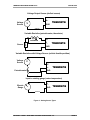
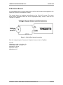
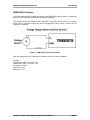
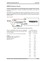
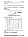
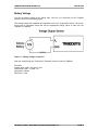
Traqmate GPS Data Acquisition System TraqData application guide Version 3.70 June 16, 2015 Copyright © 2005 - 2015 Track Systems Technologies, LLC Traqdata application guide V3.70 June 16, 2015 Traqmate, Traqview, TraqData, TraqTach, TraqCam, TraqStudio, TraqSync, the Traqmate logo, and the Track Systems logo are trademarks of Track Systems Technologies, LLC Sony, HDR-CX100, HDR-CX110, and LANC are registered trademarks of Sony Corporation. GoPro and GoPro HD are registered trademarks of Woodman Labs, Inc. Replay XD and Replay Prime X are trademarks of Stable Imaging Solutions, LLC. AEM is a trademark of AEM Electronics, Inc. PLX Is a trademark of PLX Devices, Inc. Microsoft, Windows, XP, Vista, Windows 7, and Windows 8 are trademarks of Microsoft Corp. Velcro is a trademark of Velcro Industries B.V. TraqData HD is manufactured with RaceCam Technology licensed from Northeast Microelectronics. Copyright © 2005 - 2015 Track Systems Technologies, LLC Page 2 Traqdata application guide V3.70 June 16, 2015 Table of Contents TRAQDATA INPUT DEVICES ................................................................................................................. 4 ADDING DATA INPUTS AND VIDEO CAMERAS......................................................................................... 5 CONNECTING A TACH INPUT (TRAQDATA, TRAQTACH, TRAQSYNC).......................................................................5 Changing Voltage Range of TraqTach, TraqSync, TraqData II, TraqData HD, TraqData PRO, TraqData HD2, or TraqData USB.............................................................................................................5 Selecting the Tach Signal......................................................................................................................... 5 Terminating Wire at Input Device..............................................................................................................6 CONNECTING DATA INPUTS AND OUTPUTS...........................................................................................................7 Digitals...................................................................................................................................................... 7 Analogs..................................................................................................................................................... 9 Sensor Types............................................................................................................................................ 9 PLX AIR/FUEL SENSOR................................................................................................................... 12 AEM AIR/FUEL SENSOR.................................................................................................................. 13 PLX PRESSURE SENSOR.................................................................................................................. 14 AEM FLUID PRESSURE SENSOR....................................................................................................... 15 PLX TEMPERATURE SENSOR............................................................................................................ 16 AEM FLUID TEMPERATURE SENSOR.................................................................................................. 17 BATTERY VOLTAGE.......................................................................................................................... 18 COMPLETE SENSOR LIST.................................................................................................................. 19 APPENDICES.................................................................................................................................... 20 TABLE OF FIGURES......................................................................................................................................... 20 WARRANTY INFORMATION................................................................................................................................ 21 GLOSSARY...................................................................................................................................... 22 Copyright © 2005 - 2015 Track Systems Technologies, LLC Page 3 Traqdata application guide V3.70 June 16, 2015 TraqData Input Devices Traqmate has manufactured several data input devices for the Traqmate system and all are supported. Here is a description of the devices and their capabilities. TraqTach (original) – gray 15 pin connector with 3 screw-down terminals. This device is used to connect a tach input. It came in either COIL or ELECTRONIC voltage ranges. TraqTach (revised) – black 15 pin connector with blue wire. This device is used to connect a tach input. This unit can be switched for COIL or ELECTRONIC ranges with a microswitch on the circuit board inside the connector cover. TraqSync (original) - black 15 pin connector with blue wire and RJ-45 cable. This device is used to connect a tach input and control a ChaseCam PDR-100 video recorder. This unit can be switched for COIL or ELECTRONIC ranges with a microswitch on the circuit board inside the connector cover. TraqSync PRO - black 15 pin connector with blue wire and RJ-45 cable. This device is used to connect a tach input and control a GoPro HERO2 HD video camera. This unit can be switched for COIL or ELECTRONIC ranges with a microswitch on the circuit board inside the connector cover. TraqData (original) - gray 15 pin connector with 8 screw-down terminals. This device is used to connect a tach input, 4 analog inputs, and 2 digital inputs / outputs. It came in either COIL or ELECTRONIC voltage ranges. TraqData II – 2.5” square box with removable terminal strip. This device is used to connect a tach input, 4 analog inputs, and 2 digital inputs / outputs, and control a ChaseCam PDR-100 video recorder. This unit can be switched for COIL or ELECTRONIC ranges with a microswitch on the circuit board inside the housing. TraqData HD – 2.5” square box with removable terminal strip. This device is used to connect a tach input, 4 analog inputs, and 2 digital inputs / outputs, and control a Sony HD video recorder. This unit can be switched for COIL or ELECTRONIC ranges with a microswitch on the circuit board inside the housing. TraqData PRO – 2.5” square box with removable terminal strip. This device is used to connect a tach input, 4 analog inputs, and 2 digital inputs / outputs, and control a GoPro HERO2 HD video camera. This unit can be switched for COIL or ELECTRONIC ranges with a microswitch on the circuit board inside the housing. TraqData HD2 – 2.5” square box with removable terminal strip. This device is used to connect a tach input, 4 analog inputs, and 2 digital inputs / outputs, and control a GoPro HERO2 or Replay XD HD video cameras. This unit can be switched for COIL or ELECTRONIC ranges with a microswitch on the circuit board inside the housing. TraqData USB – 2.5” square box with removable terminal strip. This device is used to connect a tach input, 4 analog inputs, and 2 digital inputs / outputs, and control a Mobius or Replay Prime X HD video cameras HD video camera. This unit can be switched for COIL or ELECTRONIC ranges with a microswitch on the circuit board inside the housing. Copyright © 2005 - 2015 Track Systems Technologies, LLC Page 4 Traqdata application guide V3.70 June 16, 2015 Adding Data Inputs and Video Cameras Connecting a Tach Input (TraqData, TraqTach, TraqSync) This requires a TraqData, TraqTach, or TraqSync interface module. The instructions are similar for each unit. The connections are the same for a TraqData, TraqData II, TraqData HD, TraqData PRO, TraqData HD2, or TraqData USB interface module. The original gray-case TraqData and TraqTach devices came in two voltage ranges, ‘Electronic’ and ‘Coil’. Later black-case TraqTachs, TraqSyncs, TraqData II and the TraqData HD, TraqData PRO, TraqData HD2, and TraqData USB modules are switchable. The ‘Electronic’ setting works with most modern cars with either a 5V or 12V tach signal. ‘Coil’ works with older cars with a 12V signal or by attaching directly to the negative coil terminal or when directly connected to an ECU. Changing Voltage Range of TraqTach, TraqSync, TraqData II, TraqData HD, TraqData PRO, TraqData HD2, or TraqData USB To open a TraqTach or TraqSync (black case), gently pry open the cover of the 15 pin connector. Be careful not to lose the thumbscrews. To open a TraqData II, TraqData HD, TraqData PRO, TraqData HD2, or TraqData USB device, remove the two screws on the bottom of the unit and lift off the top cover. For all devices, there is a very small dip switch on the circuit board that is covered in transparent tape. Use a sharp instrument to flip it to the other position. Selecting the Tach Signal First you must find a signal that pulses at least once per engine revolution. You will need to attach a wire to this signal using either a wire tap or a hard contact such as a spade lug. If you use a wire tap, take special care not to cut the source wire. There are several places where a signal may be located on your car. TraqTach/ TraqData Connection Wire Figure 1 - Tapping ECU Signal Figure 2 - Connecting to Ignition Coil Copyright © 2005 - 2015 Track Systems Technologies, LLC Page 5 Traqdata application guide V3.70 June 16, 2015 If using an MSD or similar capacitive discharge ignition use the supplied TACH signal. DO NOT CONNECT TO THE COIL. Set switch to ‘ELECTRONIC’. For older vehicles (generally 1976 and earlier), locate the ignition coil. Connect to the terminal labeled ‘– ‘. Set switch to ‘COIL’. For many modern cars, there is a 5V or 12V ECU signal labeled TACH or IGN that is a single or double pulse per engine revolution. Set switch to ‘ELECTRONIC’. For many vehicles, you can tap the wire going to the tachometer in the instrument cluster. Set switch to ‘ELECTRONIC’. For fuel-injected vehicles, you can use a fuel injector signal. Set switch to ‘COIL’. For distributor-less ignition, you can use a low voltage coil-on-plug signal at the plug or the ECU. Set switch to ‘COIL’. Terminating Wire at Input Device Attach a wire to your tach signal source. For original TraqTach and either TraqData input modules, run a wire to the module and terminate it securely in the screwdown terminal labeled ‘RPM’. For black-case TraqTach and TraqSync modules, connect the tach signal to the TraqSync blue wire using the supplied crimpless connector. Plug the input module into the Traqmate Sensor Unit. If you are operating Traqmate on vehicle power, there is only one connection required. If you are operating on battery power (not recommended for TraqTach or TraqData), you must connect the terminal labeled ‘GND’ to vehicle ground or ground the Traqmate Sensor Unit case. Refer to the applicable Traqview or TraqDash User Manuals to set up Traqmate so that the proper RPM is displayed on the unit and in Traqview. See TraqDash or Traqmate Classic User Manuals for instructions on configuring the RPM ranges and number of cylinders. Copyright © 2005 - 2015 Track Systems Technologies, LLC Page 6 Traqdata application guide V3.70 June 16, 2015 Connecting Data Inputs and Outputs Traqmate can deliver amazing results with just the internal GPS and accelerometers but sometimes you want to monitor other external points in the car such as air/fuel mixture for tuning the vehicle or perhaps steering angle to better evaluate driver and setup. For this purpose, Track Systems offers the TraqData analog and digital input device. TraqData contains screwdown terminals for 4 Analog, 2 Digital, and 1 RPM connections. It also contains a 5V reference line for resistive sensors. TraqData modules also have a 12V power line that can be used to power a sensor up to 100mA. TraqData is a convenient way to monitor external sensors for temperature, pressure, deflection, or just about anything else. However, connecting electrical components requires some knowledge of voltage, current, and wiring. If you hook up something wrong, you risk damage to yourself, your vehicle, and your Traqmate. If you do not have electrical knowledge, get help from your Traqmate dealer or a friend with the proper experience. Digitals Inputs Digital Inputs are straightforward. Tie them to a signal that measures between 0V and 0.5V in one state and between 3V and 20V in the other state. An example is the brake light. Tap the wire going to the brakes and attach it to either the D4 or D5 terminal. 0V is a logic 0, 3V+ is a logic 1. If input is not connected it will read as a 1. You can change the definitions of the digital points to define “ON” and “OFF” using Traqview. If a ChaseCam PDR or Sony camcorder is connected, D4 cannot be used as an input. NEVER CONNECT A DIGITAL INPUT TO THE COIL OR OTHER HIGH VOLTAGE SOURCE. Do not configure the Digitals as Outputs in Traqview if they are connected as Inputs. This could damage Traqmate and/or the vehicle. Outputs Digital Outputs are used to signal when a pre-programmed event occurs. When activated, they form a connection to ground. Each Digital Output is an open-collector signal and will normally read approximately 2 Volts when not “activated”. IF ANY CAMERA IS CONNECTED, D4 SHOULD NOT BE USED. Otherwise, Digital Output D4 may be used as an alarm notification for RPM or the A0 Analog input. D5 may be used as an alarm notification for RPM or the A1 Analog input. When used as an alarm, these outputs can be used to trigger a relay to an external warning light or directly drive a low-current indicator such as an LED. The figure below shows the connections required to connect an external light or LED to a digital output. The max sink current on each digital output is 250mA. If you use a relay, you must have a current limiting diode for the flyback current as shown below. Copyright © 2005 - 2015 Track Systems Technologies, LLC Page 7 Traqdata application guide V3.70 June 16, 2015 +12V from Vehicle Relay 1N4003 currentlimiting diode Traqdata Dn Lamp or other load GND Connection to Warning Lamp or High Current Load +12V from Vehicle Current Limiting Resistor Traqdata Dn LED Connection to LED or Low Current Load Figure 3 - Digital Output Connections Copyright © 2005 - 2015 Track Systems Technologies, LLC Page 8 Traqdata application guide V3.70 June 16, 2015 Analogs Analogs are a little trickier. There are many ways they can be attached depending on the electrical characteristics of the sensor. Sensor Types There are several types of analogs. Determine what you have before proceeding. Diagrams for connection of these sensor types are shown in Figure 4. 1. Voltage output. This is a powered sensor such as an AEM, Innovate, or PLX Air/Fuel sensor or a PLX Fluid Pressure Sensor. Typically these sensors output a linear 0V – 5V signal. This is the best type of sensor. It is very accurate and provides the most resolution for logging. 2. Variable Resistive. This type of sensor changes resistance with changes in movement or property. Examples include a string potentiometer, a linear potentiometer, or a thermistor based temperature sensor such as an AEM water temperature sensor. This type of sensor is inexpensive but requires a resistor, can be non-linear (inaccurate), and does not use all of the Traqmate input voltage range. The resistance change over the operating range must be greater than 470Ω. More resistance change is better. 3. Resistive with vehicle voltage source. Examples include a factory throttle position sensor. This sensor is a #2 type but acts like a #1 in that it has a voltage output. If the sensor resistance is too low, connecting to the Traqmate can affect the readings to the vehicle. 4. Gauge Sending Unit. Sometimes you can connect to an existing gauge electrical sending unit to log the information on the gauge. Connecting to a gauge is like getting a free input but not all gauges are suitable. Total voltage change over operating range needs to be at least 3V for practical use. Connecting to the Traqmate can interfere with the accuracy of the gauge. Copyright © 2005 - 2015 Track Systems Technologies, LLC Page 9 Traqdata application guide V3.70 June 16, 2015 Voltage Output Sensor (air/fuel sensor) + Voltage Source An V GND - Traqdata optional Variable Resistive (potentiometer, thermistor) 470 minimum 5V An Sensor Traqdata GND Variable Resistive with Voltage Source (vehicle throttle position) + Voltage Source V 5V - An Potentiometer Traqdata GND Input to existing gauge (water temperature) + An Electric Gauge GND - Traqdata optional Figure 4 - Analog Sensor Types Copyright © 2005 - 2015 Track Systems Technologies, LLC Page 10 Traqdata application guide V3.70 June 16, 2015 Connection Rules 1. Do not use the vehicle’s 12V power or the TraqData 12V connection) as a reference voltage as it changes depending on charging status. Use the supplied 5V source instead. 2. The maximum voltage you can monitor is 20V. Do not exceed this or you can damage the Traqmate. 3. If you are using batteries (not recommended for TraqData), you must connect the sensor ground to the TraqData GND terminal. 4. If you are operating off vehicle power (recommended), your sensor circuit must be grounded to the vehicle or attached to the TraqData GND terminal. 5. If you place sensors near high voltage sources you may corrupt your signal with electromagnetic interference. Requirements To setup and use TraqData you will need the following: Traqmate Complete, Traqmate Basic, or TraqDash System TraqData input module PC with Traqview installed (except TraqDash) 20 gauge or smaller wire (the higher the gauge the smaller the wire) This is a size issue not an electrical issue. Larger wire will not fit into the screwdown terminals on the TraqData or TraqTach device. Means to terminate wires (spade lugs, wire taps, solder, ring lugs, etc.) Very small screwdriver for screwdown terminals (blade < 0.08” or 2 mm) Crimper tool Wire cutters Wire strippers Volt-Ohm Meter (VOM) Sensors and series resistors as desired Analog Input Installation Overview See detailed instructions for these steps in subsequent pages. 1. Identify which input points are to be monitored. These could be points already available in the vehicle (electric oil pressure gauge) or require new sensors (steering wheel deflection). 2. Give each point a name and identify the units in which to report this input point. (i.e. PSI, Ratio, Deg-C, Degrees, or possibly just Volts). If the value you want is not on the list you can just type it in. 3. Wire up a sensor with an appropriate series resistor (if necessary). 4. Measure the resistance or voltage at either end of the range. For example, if you are using a thermocouple, heat it to the max temperature and cool it to the min temperature and measure the temperature and resistance/voltage at either extreme. You can measure the voltage using the Inputs screen on the Display Unit or with a VOM. 5. Enter the information into Traqview or on the TraqDash and enable the data point. 6. Turn on data collection (must have GPS signal!) and record some data. 7. Upload into Traqview and verify the results. Tweak as necessary. Many customers use sensors purchased from AEM or PLX which provide a convenient and accurate linear 5V output that is perfect for the TraqData input device. Copyright © 2005 - 2015 Track Systems Technologies, LLC Page 11 Traqdata application guide V3.70 June 16, 2015 PLX Air/Fuel Sensor A recommended sensor for logging air/fuel ratio is the PLX Air/Fuel Sensor that supplies a 0-5V output that is perfect for use with the Traqmate. This example shows the installation and calibration of the PLX Air/Fuel sensor. The sensor comes with an information sheet that lists the appropriate scaling values to enter into the Traqmate or TraqDash. Figure 5 – PLX Air/Fuel Sensor Connection Enter this voltage range into Traqview (for Traqmate Classic) or into the TraqDash. 5V Scale Voltage range: LOW = 0V, HIGH = 5V Value range: LOW = 10, HIGH = 20 Input Name = AirFuel Input Units = Ratio Alarm Above 13.7 Copyright © 2005 - 2015 Track Systems Technologies, LLC Page 12 Traqdata application guide V3.70 June 16, 2015 AEM Air/Fuel Sensor A recommended sensor for logging air/fuel ratio is the AEM UEGO Air/Fuel Sensor or Gauge that supplies a 0-5V output that is perfect for use with the Traqmate. This example shows the installation and calibration of the AEM Air/Fuel sensor. The sensor comes with an information sheet that lists the appropriate scaling values to enter into the Traqmate or TraqDash. Figure 6 – AEM Air/Fuel Sensor Connection Enter this voltage range into Traqview (for Traqmate Classic) or into the TraqDash. 5V Scale Voltage range: LOW = 0V, HIGH = 5V Value range: LOW = 8.5, HIGH = 18.0 Input Name = AirFuel Input Units = Ratio Alarm Above 13.7 Copyright © 2005 - 2015 Track Systems Technologies, LLC Page 13 Traqdata application guide V3.70 June 16, 2015 PLX Pressure Sensor A recommended sensor for logging oil pressure, fuel pressure, brake pressure, or any other fluid measurement is the PLX Pressure Sensor that supplies a voltage output that is compatible for use with the Traqmate. This example shows the installation and calibration of the PLX Pressure Sensor. The sensor comes with an information sheet that lists the appropriate scaling values to enter into the Traqmate or TraqDash. Figure 7 – PLX Pressure Sensor Connection Enter this voltage range into Traqview (for Traqmate Classic) or into the TraqDash. 5V Scale Voltage range: LOW = 0V, HIGH = 3.75V Value range: LOW = 0, HIGH = 150 Input Name = Pressure Input Units = PSI Copyright © 2005 - 2015 Track Systems Technologies, LLC Page 14 Traqdata application guide V3.70 June 16, 2015 AEM Fluid Pressure Sensor A sensor for pressure measurement is the AEM 30-2130 series of sensors that come in a variety of pressure ranges and supply a 0-5V output compatible with the Traqmate. These sensors can be used for measurement of oil pressure, fuel pressure, brake pressure, or any other fluid measurement. This example shows the installation and calibration of the AEM 30-2130-100 sensor. The sensor comes with an information sheet that lists the appropriate scaling values to enter into the Traqmate or TraqDash. There is some variability from sensor to sensor so additional calibration may be required. Connect as shown: Figure 8 – AEM 30-2130 Pressure Sensor Connection Using the AEM-supplied chart, choose the appropriate voltage range and enter into Traqview (for Traqmate Classic) or into the TraqDash. For an oil pressure from 0 to 100 PSI, enter the following: 5V Scale Voltage range: LOW = 0.5, HIGH = 4.5V Value range: LOW = 0, HIGH = 100 Input Name = Oil Press Input Units = PSI Copyright © 2005 - 2015 Track Systems Technologies, LLC Page 15 Traqdata application guide V3.70 June 16, 2015 PLX Temperature Sensor A recommended sensor for logging water or oil temperature is the PLX Temperature Sensor that supplies a voltage output that is compatible for use with the Traqmate. This example shows the installation and calibration of the PLX Temperature Sensor. The sensor comes with an information sheet that lists the appropriate scaling values to enter into the Traqmate or TraqDash. Figure 9 – PLX Temperature Sensor Connection Enter this voltage range into Traqview (for Traqmate Classic) or into the TraqDash. 5V Scale Voltage range: LOW = 0V, HIGH = 5V Value range: LOW = 32, HIGH = 230 Input Name = Temperature Input Units = DegF Copyright © 2005 - 2015 Track Systems Technologies, LLC Page 16 Traqdata application guide V3.70 June 16, 2015 AEM Fluid Temperature Sensor A recommended sensor for temperature measurement is the AEM 30-2012. This is a resistive sensor that can be used for water or oil temperature measurement. You will need to source a ½ watt 2.2K Ohm resister. This example shows the installation and calibration of the AEM 30-2012 sensor. The sensor comes with an information sheet that lists the appropriate scaling values to enter into the Traqmate or TraqDash. There is some variability from sensor to sensor so additional calibration may be required. Connect the sensor as shown: Figure 10 – AEM 30-2012 Temperature Sensor Connection Using the AEM-supplied chart, choose the appropriate voltage range and enter into Traqview (for Traqmate Classic) or into the TraqDash. For a water temperature application from 100 degrees F to 250 degrees F, enter the following: 5V Scale Voltage range: LOW = 0.69V, HIGH = 3.63V Value range: LOW = 257, HIGH = 104 Note inverted scale Input Name = Water Temp Input Units = DegF Copyright © 2005 - 2015 Track Systems Technologies, LLC Page 17 Traqdata application guide V3.70 June 16, 2015 Battery Voltage You can log battery voltage as an analog input. Loop the 12V connection on the TraqData module over to one of the analog inputs. This example shows the installation and calibration of the PLX Temperature Sensor. The sensor comes with an information sheet that lists the appropriate scaling values to enter into the Traqmate or TraqDash. Figure 11 – Battery Voltage Connection Enter this voltage range into Traqview (for Traqmate Classic) or into the TraqDash. 20V Scale Voltage range: LOW = 0V, HIGH = 20V Value range: LOW = 0, HIGH = 20 Input Name = Battery Input Units = Volts Copyright © 2005 - 2015 Track Systems Technologies, LLC Page 18 Traqdata application guide V3.70 June 16, 2015 Complete Sensor List Here is a list of the scale values for many compatible sensors. This information is also available in the TraqDash Analog Input screen help page. ** AEM AirFuel ** Volts: LOW 0V HIGH 5V Values: LOW 8.5 HIGH 18.0 5 Volt Range Units = Ratio Alarm Above 13.7 ** AEM 75PSI MAP Sensor ** Volts: LOW 0.5V HIGH 4.5V Values: LOW -14.7 HIGH 35.3 5 Volt Range Units = PSI ** AEM Temperature Sensor ** Volts: LOW 0.016V HIGH 0.9V Values: LOW 32.0 HIGH 230.0 5 Volt Range Units = DegF ** PLX AirFuel ** Volts: LOW 0V HIGH 5V Values: LOW 10.0 HIGH 20.0 5 Volt Range Units = Ratio Alarm Above 13.7 ** PLX Pressure Sensor ** Volts: LOW 0.0V HIGH 3.75V Values: LOW 0.0 HIGH 150.0 5 Volt Range Units = PSI ** PLX Temperature Sensor ** Volts: LOW 0.0V HIGH 5.0V Values: LOW 32.0 HIGH 302.0 5 Volt Range Units = DegF ** PLX Exhaust Temperature ** Volts: LOW 0.0V HIGH 3.33V Values: LOW 32.0 HIGH 1000.0 5 Volt Range Units = DegF ** PLX Boost Sensor ** Volts: LOW 0.0V HIGH 5V Values: LOW -15 HIGH 30 5 Volt Range Units = PSI ** Innovate LC-1 AirFuel ** Volts: LOW 0V HIGH 5V Values: LOW 7.35 HIGH 22.33 5 Volt Range Units = Ratio Alarm Above 13.7 ** Battery Voltage ** Volts: LOW 0V HIGH 20V Values: LOW 0.0 HIGH 20.0 20 Volt Range Units = Volts Alarm Below 11.5 Copyright © 2005 - 2015 Track Systems Technologies, LLC Page 19 Traqdata application guide V3.70 June 16, 2015 Appendices Table of Figures FIGURE 1 - TAPPING ECU SIGNAL...................................................................................................... 5 FIGURE 2 - CONNECTING TO IGNITION COIL........................................................................................... 5 FIGURE 3 - DIGITAL OUTPUT CONNECTIONS.......................................................................................... 8 FIGURE 4 - ANALOG SENSOR TYPES.................................................................................................. 10 FIGURE 5 – PLX AIR/FUEL SENSOR CONNECTION..............................................................................12 FIGURE 6 – AEM AIR/FUEL SENSOR CONNECTION.............................................................................13 FIGURE 7 – PLX PRESSURE SENSOR CONNECTION.............................................................................14 FIGURE 8 – AEM 30-2130 PRESSURE SENSOR CONNECTION..............................................................15 FIGURE 9 – PLX TEMPERATURE SENSOR CONNECTION.......................................................................16 FIGURE 10 – AEM 30-2012 TEMPERATURE SENSOR CONNECTION......................................................17 FIGURE 11 – BATTERY VOLTAGE CONNECTION...................................................................................18 Copyright © 2005 - 2015 Track Systems Technologies, LLC Page 20 Traqdata application guide V3.70 June 16, 2015 Warranty Information Track Systems warrants to the owner of this Traqmate GPS Data Acquisition System that it is free from defects in materials and workmanship for a period of 180 days from the original date of consumer purchase. This warranty does not cover damage to the product as a result of misuse or accident, including but not limited to shock or water damage. Remedies shall be limited to repair or replacement of the defective unit at Track Systems discretion. IN NO EVENT SHALL TRACK SYSTEMS BE LIABLE FOR INCIDENTAL OR CONSEQUENTIAL DAMAGES. Some states do not allow for limitation of incidental or consequential damages, so this limitation may not apply to you. To arrange for service, check the Traqmate website at http://traqmate.com and click the Service and Repair button to create a repair ticket. This applies to both in and out of warranty service. For technical support, call 1-877-289-0312 (9 AM to 5 PM EST M-F). Copyright © 2005 - 2015 Track Systems Technologies, LLC Page 21 Traqdata application guide V3.70 June 16, 2015 Glossary Accelerometer Analysis A sensor that measures the G-forces on the vehicle The effort of examining recorded data for useful information Analysis File File with extension of “.tqs” that contains an analysis. May contain one or more sessions AutoOn Feature to allow Traqmate to automatically turn on with power AutoStart Feature to designate automatic starting mode for Traqmate AutoPan A Traqview feature that causes the AutoPan Vehicle to remain in the Track window regardless of Zoom level AutoPan Vehicle The vehicle selected in Traqview menu to be followed during AutoPan Data Acquisition Measuring and recording of information Display Unit Lap Timer component of the Traqmate Complete System DU Display Unit Firmware Software that is embedded into the SU and DU that controls their operation GPS Global Positioning System, a satellite-based location method Post Roll Video recorded after the selected Laps Predictive Lap Timer Display Unit timer that compares current lap progress with a stored reference lap Pre Roll Video recorded before the selected Laps Reference Vehicle In Traqview, first vehicle selected for map display Segment portion of the track that is being analyzed in Segment Analysis Segment Separator bent line on Track Map that separates segments Sensor Unit Silver box containing GPS receiver and accelerometers Session One group of continuous recording, typically a single trip or series of laps Session File File with extension of “.tqm” that contains one recorded session Slider Slide control at bottom of screen for positioning vehicle on track Start/Finish Line Place on track where a lap starts SU Sensor Unit Theoretical Best Lap (TBL) Best combinations of segment times from a session TraqData Analog, Digital and RPM input module TraqData II Analog, Digital and RPM input module with 4-wire ChaseCam interface TraqData HD Analog, Digital and RPM input module with LANC camera interface TraqData PRO Analog, Digital and RPM input module with GoPro Camera interface TraqData HD2 Analog, Digital and RPM input module, GoPro & Replay XD Camera TraqData USB Analog, Digital and RPM input module, Mobius & Replay Prime X Camera TraqPaq Traqmate Battery Pack Traqmate Basic GPS Data Acquisition system without a Display Unit (Sensor Unit only) Traqmate Complete GPS Data Acquisition system with both Sensor Unit and Display Unit TraqSync RPM input module with 4-wire ChaseCam interface TraqSync PRO RPM input module with GoPro Camera interface TraqTach RPM input module Traqview Windows data playback and analysis program TraqStudio Windows data and video playback and analysis program Copyright © 2005 - 2015 Track Systems Technologies, LLC Page 22