1
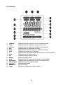
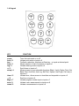
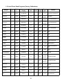
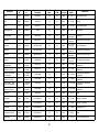
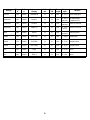
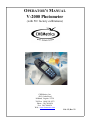
OPERATOR’S MANUAL
V-2000 Photometer
(with 50+ factory calibrations)
CHEMetrics, Inc.
4295 Catlett Road
Midland, Virginia 22728
Toll Free 1-800-356-3072
Phone: 540-788-9026
Fax: 540-788-4856
Web: www.chemetrics.com
Feb. 15, Rev. 22
Table of Contents
Chapter 1 - Introduction
1-1
Battery Installation . . . . . . . . . . . . . . . . . . . . . . . . . . . . . . . . . .
1
1-2
Sample Cell Adapters . . . . . . . . . . . . . . . . . . . . . . . . . . . . . . . .
1
1-3
LCD Display . . . . . . . . . . . . . . . . . . . . . . . . . . . . . . . . . . . . . . .
2
1-4
Keypad . . . . . . . . . . . . . . . . . . . . . . . . . . . . . . . . . . . . . . . . . . .
3
1-5
List of Direct Read Programs (Factory Calibrations) . . . . . . . .
4
Chapter 2 - Setup Menu Functions
2-1
Blank . . . . . . . . . . . . . . . . . . . . . . . . . . . . . . . . . . . . . . . . . . . . .
7
2-2
Verify . . . . . . . . . . . . . . . . . . . . . . . . . . . . . . . . . . . . . . . . . . . .
7
2-3
Digits . . . . . . . . . . . . . . . . . . . . . . . . . . . . . . . . . . . . . . . . . . . . .
7
2-4
Clock . . . . . . . . . . . . . . . . . . . . . . . . . . . . . . . . . . . . . . . . . . . . .
8
2-5
Set Baud . . . . . . . . . . . . . . . . . . . . . . . . . . . . . . . . . . . . . . . . . .
8
2-6
Print . . . . . . . . . . . . . . . . . . . . . . . . . . . . . . . . . . . . . . . . . . . . .
8
2-7
Auto Print . . . . . . . . . . . . . . . . . . . . . . . . . . . . . . . . . . . . . . . . .
9
2-8
Auto Log . . . . . . . . . . . . . . . . . . . . . . . . . . . . . . . . . . . . . . . . . .
9
2-9
Self-Test . . . . . . . . . . . . . . . . . . . . . . . . . . . . . . . . . . . . . . . . . .
9
2-10 Upload . . . . . . . . . . . . . . . . . . . . . . . . . . . . . . . . . . . . . . . . . . .
9
Chapter 3 - Setup and Measurement Procedures
3-1
General Operating Instructions . . . . . . . . . . . . . . . . . . . . . . . . .
10
3-2
Procedure A - Zeroing, Program Selection and Measuring . . .
10
3-3
Procedure B - Zeroing, Program Selection, Setting Reagent Blank
and Measuring . . . . . . . . . . . . . . . . . . . . . . . . . . . . . . . . . . .
11
Chapter 4 - Data Logging
4-1
Logging Data Manually . . . . . . . . . . . . . . . . . . . . . . . . . . . . . . .
12
4-2
Logging Data Automatically . . . . . . . . . . . . . . . . . . . . . . . . . . .
12
4-3
Displaying the Log . . . . . . . . . . . . . . . . . . . . . . . . . . . . . . . . . .
12
4-4
Clearing the Log . . . . . . . . . . . . . . . . . . . . . . . . . . . . . . . . . . . .
12
Chapter 5 - Use with Printers and Computers
5-1
Printing Logged Data Directly to a Printer . . . . . . . . . . . . . . . . .
13
5-2
Downloading Logged Data to a Computer . . . . . . . . . . . . . . . .
13
5-3
Uploading Method Revisions . . . . . . . . . . . . . . . . . . . . . . . . . .
14
Chapter 6 - Error Messages . . . . . . . . . . . . . . . . . . . . . . . . . . . . . . . . . .
16
Chapter 7 - Custom User Programs
7-1
Creating a Custom User Program . . . . . . . . . . . . . . . . . . . . . .
17
7-2
Calibrating a Custom User Program . . . . . . . . . . . . . . . . . . . . .
18
7-3
Replacing or Reviewing a Custom User Program . . . . . . . . . .
18
Chapter 8 - Specifications & Features . . . . . . . . . . . . . . . . . . . . . . . . .
19
Chapter 9 - Product Information
9-1
Instrument & Accessories . . . . . . . . . . . . . . . . . . . . . . . . . . . . .
20
9-2
Warranty Information . . . . . . . . . . . . . . . . . . . . . . . . . . . . . . . .
20
9-3
European Union’s WEEE Directive 2002/96/EC . . . . . . . . . . . .
20
Chapter 1
Introduction
1-1 Battery Installation
The V-2000 requires 4 AA alkaline or lithium batteries. With alkaline batteries, the expected life
is 2,500 hours of operation. With lithium batteries, the expected life is 10,000 hours of operation.
The V-2000 has a battery saving auto-shutoff feature that turns the instrument off after 20
minutes of non-use. Remove batteries when photometer is not in use.
To install batteries, carefully loosen the 2 captive screws on the battery cover (back of
instrument). Remove the cover, and insert the batteries with the correct orientation as illustrated
in the battery compartment. Replace the battery cover and replace the captive screws.
1-2 Sample Cell Adapters
The V-2000 comes with 2 sample cell adapters: 13 mm adapter for Vacu-vials; 16 mm adapter
for COD Vials. The adapters ensure correct alignment of the ampoule or vial being used. If the
ampoule or vial is not aligned correctly (i.e. wrong adapter or no adapter is used), measurement
errors will occur.
To insert an adapter, the male tabs on the adapter (left and right sides) should be matched up
with the alignment slots to the left and right of the sample cell compartment. Insert the adapter
with the correct alignment and push down firmly until it snaps into place.
Important Note:
Above the sample cell compartment, the instrument says
“cuvette adapter = lock-unlock <”. Disregard this message!
There is no lock, unlock feature to the current cell adapters.
They go straight in and out. DO NOT attempt to turn the
adapter from left to right when inserting it or removing it.
1
1-3 LCD Display
1
2
3
4
5
6
7
8
9
10
11
12
13
14
15
16
calibrate
setup
measure
zero
blank
units
?
timer
log
battery
print
verification
XXX program
ÇÇÇÇÇÇÇÇ
-8.8:8.8
range
Displays when the instrument is in the calibration mode
Displays when the instrument is in the setup mode
Displays when the instrument is taking a measurement
Displays when the instrument is zeroing
Displays when a blank is active for a selected method
Displays the chosen unit of measure
Displays when the instrument is prompting the user for a response
Displays when the timer is active
Displays if data is stored in the log
Displays if battery is low
Displays when the instrument is printing (or downloading)
Displays when the instrument is in the verification mode
Displays the active program number
Alphanumeric display
Numeric display
Displays to indicate over range condition
2
1-4 Keypad
KEY
power
print / 0
yes / .
units / 1
log / 2
? /3
setup / 4
timer / 5
>/6
prgm / 7
zero / 8
meas / 9
FUNCTION
Turns the instrument on or off
Initiates print mode or inputs a 0
Confirms a selection, functions as Enter key, or inputs a decimal point
Allows selection of unit of measure or inputs a 1
Initiates data log mode or inputs a 2
Scroll down or inputs a 3
Allows access to user selectable functions (Blank, Verify, Digits, Clock, Set
Baud, Print, AutoPrint, Auto Log, Self-Test, Upload, User Prgm, Cal User) or
inputs a 4
Initiates timer, allows access to time/date and stopwatch or inputs a 5
Scroll up or inputs a 6
Initiates program number input or inputs a 7
Initiates a zero measurement or inputs an 8
Initiates a measurement or inputs a 9
3
1-5 List of Direct Read Programs (Factory Calibrations)
Prog.
#
Kit Cat.
#
Instrument
Display
Aluminum
9
K-0603
ALUMINUM
13
Y
520
0 - 0.25
Ammonia
14
K-1403
AMMONIA3
13
N
610
0 - 30.00
Salicylate
(as N)
Ammonia
15
K-1503
AMMONIA
13
N
420
0 - 7.00
(as N)
Direct Nesslerization
Ammonia
16
K-1523
AMMONIA2
13
N
420
0 - 14.0
(as N)
Direct Nesslerization
Bromine
22
K-1613
BROMINE
13
N
520
0 - 12.0
DPD
Chloride
26
K-2103
CHLORIDE
13
Y
420
0 - 40.0
Ferric Thiocyanate
Chlorine
32
K-2513
CHLOR 2
13
N
520
0 - 5.00
DPD
Chlorine
32
K-2523
CHLOR 2
13
N
520
0 - 5.00
DPD
Chlorine
Dioxide
37
K-2703
CLORDIOX
13
N
520
0 - 11.0
DPD
Chromate
42
K-2803
CHROM
13
N
520
0 - 3.50
Diphenylcarbazide
(as CrO4)
Copper
55
K-3503
COPPER
13
N
420
0 - 12.00 Bathocuproine
Cyanide
60
K-3803
CYANIDE
13
Y
610
0 - 0.400
Isonicotinic/Barbituric
Acid
DEHA
64
K-3903
DEHA 1
13
N
580
0 - 2.00
PDTS
Formaldehyde
78
K-4203
FORMALD
13
N
520
0 - 8.00
Purpald
Glycol
83
K-4403
GLYCOL
13
N
520
0 - 10.0
(as EG)
Purpald/Periodate
Glycol
84
K-4423
GLYCOL 2
13
N
520
0 - 200
(as PG)
Purpald/Periodate
89
K-5003
HYDRAZ
13
Y
420
0 - 1.20
PDMAB
Peroxide
93
K-5513
PEROX
13
N
520
0 - 3.00
DPD
Peroxide
95
K-5543
PEROX 2
13
N
520
0 - 6.00
Ferric Thiocyanate
Iron
100
K-6003
IRON 1
13
N
520
0 - 6.00
Phenanthroline
Analyte
Hydrazine
Cell Size, Blank Wavemm
Y/N length
4
Range
ppm
Method
Eriochrome Cyanine R
Prog.
#
Kit Cat.
#
Instrument
Display
Iron
101
K-6013
IRON 3
13
N
420
0 - 25.0
Phenanthroline
Iron
102
K-6023
IRON 2
13
N
580
0 - 2.50
PDTS
Iron
100
K-6203
IRON 1
13
N
520
0 - 6.00
Phenanthroline
Manganese
110
K-6503
MN
13
N
520
0 - 30.0
Periodate
Molybdate
115
K-6703
MOLYB
13
N
420
0 - 25.0
(as Mo)
Catechol
Nitrate
119
K-6903
NITRATE
13
N
520
0 - 1.50
(as N)
Cadmium Reduction
Nitrate
122
K-6913
NITRATE4
13
N
520
0 - 1.50
(as N)
Zinc Reduction
Nitrate
120
K-6923
NITRATE2
13
N
520
0 - 7.5
(as N)
Cadmium Reduction
Nitrate
121
K-6933
NITRATE3
13
N
520
0 - 50.0
(as NO3)
Cadmium Reduction
Nitrite
125
K-7003
NITRITE
13
N
520
0 - 1.00
(as N)
Azo Dye Formation
COD LR, EPA
Accepted
48
K-7350S
K-7355
COD LR
16
Y
420
0 - 150
Dichromate Reactor
Digestion
COD LR,
Mercury Free
48
K-7351S
K-7356
COD LR
16
Y
420
0 - 150
Dichromate Reactor
Digestion
COD HR, EPA
Accepted
49
K-7360S
K-7365
COD HR
16
Y
610
0 - 1500
Dichromate Reactor
Digestion
COD HR,
Mercury Free
49
K-7361S
K-7366
COD HR
16
Y
610
0 - 1500
Dichromate Reactor
Digestion
COD HR+, Not
EPA Accepted
49
K-7370S
K-7375
COD HR
16
Y
610
0 - 15,000
Dichromate Reactor
Digestion
COD HR+,
Mercury Free
49
K-7371S
K-7376
COD HR
16
Y
610
0 - 15,000
Dichromate Reactor
Digestion
Ozone
133
K-7423
OZONE
13
N
520
0 - 5.00
DPD
Oxygen
140
K-7503
OXYGEN 1
13
N
610
0 - 2.00
Indigo Carmine
Oxygen
141
K-7513
OXYGEN 2
13
N
520
0 - 15.0
Indigo Carmine
Oxygen
142
K-7553
OXYGEN 3
13
N
520
0 - 1.000
Rhodazine D™
Peracetic Acid
148
K-7913
PERACET
13
N
520
0 - 5.00
DPD
Phenols
152
K-8003
PHENOLS
13
N
520
0 - 8.00
4-Aminoantipyrine
Analyte
Cell Size, Blank Wavemm
Y/N length
5
Range
ppm
Method
Prog.
#
Kit Cat.
#
Instrument
Display
Phenols
153
K-8023
PHENOLS2
13
N
520
0 - 20.0
4-Aminoantipyrine
Phosphate
158
K-8503
PHOS 1
13
N
420
0 - 80.0
(as PO4)
Vanadomolybdophosphoric Acid
Phosphate
159
K-8513
PHOS 2
13
N
610
0 - 8.00
(as PO4)
Stannous Chloride
Phosphate
160
K-8513
PHOS 2 P
13
N
610
0 - 2.64
(as P)
Stannous Chloride
Silica
168
K-9003
SILICA
13
N
610
0 - 10.00
Heteropoly Blue
(as SiO2)
Sulfate
174
K-9203
SULFATE
13
N
420
0 - 100.0 Turbidimetric
Sulfide
179
K-9503
SULFIDE
13
N
610
0 - 3.00
Methylene Blue
Sulfide
180
K-9523
SULFIDE2
13
N
610
0 - 6.00
Methylene Blue
Zinc
187
K-9903
ZINC
13
N
610
0 - 3.00
Zincon
Zinc
188
K-9923
ZINC 2
13
N
610
0 - 15.0
Zincon
Analyte
Cell Size, Blank Wavemm
Y/N length
6
Range
ppm
Method
Chapter 2
Setup Menu Functions
To view the Setup menu functions, press the setup key and use the • or – keys to scroll through the
list of functions.
2-1 Blank
The blank function is employed for specific methods that require the generation and use of a reagent
blank ampoule or vial. See table in section 1-5 and the product specific instructions for methods that
require the use of a reagent blank. The procedure for using the blank function is found in Chapter 3,
Section 3-3 Procedure B - Zeroing, Program Selection, Setting Reagent Blank and Measuring. Detailed
directions for generating a reagent blank are in the product specific instructions.
The V-2000 automatically displays the BLANK icon when the selected method requires a reagent blank.
If the blank is accidentally set (BLANK icon appears on the LCD display for a method that does not
employ a reagent blank), it is important to clear the blank before running the method.
To Clear Blank:
1. Press the setup key and use the • or – keys until “BLANK” is displayed, then press the yes key.
2. “SET BLNK?” will be displayed.
3. Use the • or – keys to toggle from “SET BLNK?” to “CLR BLNK”. When “CLR BLNK” is displayed,
press the yes key.
4. “CLEARED” will be displayed.
5. Press the meas key to exit the setup menu.
2-2 Verify
Disregard this function. It offers no added value to the instrument user.
2-3 Digits
The digits function allows the user to select the resolution of the reading (the number of significant digits
in the displayed test result): 0.000, 0.00, 0.0, and 0. The default setting for this function is 0.000, however
the test range on the parameter specific test kit instructions and in the List of Supported Parameters in
Chapter 9 of this manual is displayed with the suggested number of significant digits for each particular
method.
NOTE:
The digits resolution setting on the V-2000 is not method specific, and therefore must be reset as
needed when moving from one preprogrammed method to another.
7
1.
2.
3.
Press the setup key and use the • or – keys until “DIGITS” is displayed, then press the yes key.
Use the • or – keys until the desired resolution is displayed, then press the yes key.
Press the meas key to exit the setup menu.
2-4 Clock
The clock function allows the user to set the time and date.
1.
2.
3.
4.
5.
6.
Press the setup key and use the • or – keys until “CLOCK” is displayed, then press the yes key.
“20__” will be displayed. Enter the year.
“__Month” will be displayed. Enter the month.
“__Day” will be displayed. Enter the day.
“__:__ (24) hour” will be displayed. Enter the time.
Press the meas key to exit the setup menu.
2-5 Set Baud
The set baud function allows the user to select the baud rate:1200, 2400, 4800, and 9600. The default
setting for this function is 1200.
1.
2.
3.
Press the setup key and use the • or – keys until “SET BAUD” is displayed, then press the yes
key.
Use the • or – keys until the desired baud rate is displayed, then press the yes key.
Press the meas key to exit the setup menu.
2-6 Print
The print function allows the user to select the printout format. The user can select between a standard
printout (used if printing directly to a printer) and a comma delimited format (used for importing data into
a spreadsheet).
1.
2.
3.
Press the setup key and use the • or – keys until “PRINT” is displayed, then press the yes key.
Use the • or – keys to toggle between “STND PRN” and “CMA DELM”. When the desired printout
format is displayed, press the yes key.
Press the meas key to exit the setup menu.
8
2-7 Auto Print
The auto print function allows the user to automatically send readings to a printer.
1.
2.
3.
Press the setup key and use the • or – keys until “AUTO PRT” is displayed, then press the yes
key.
Use the • or – keys to toggle between “AUTO OFF” and “AUTO ON”. When the desired printing
function is displayed, press the yes key.
Press the meas key to exit the setup menu.
2-8 Auto Log
The auto log function allows the user to automatically save up to 100 test results in the photometer’s
memory. The procedure for using the auto log function is found in Chapter 4, Section 4-2 Logging Data
Automatically.
2-9 Self-Test
The self-test function puts the photometer into self-diagnostic mode. It is not recommended as a routine
test, but rather as a troubleshooting tool to be used if the unit gives an error message, produces a
suspect test result or in any way malfunctions. If an instrument fails any portion of the self-test, contact
CHEMetrics Technical Services Department.
1.
2.
3.
4.
5.
6.
7.
Before initiating the self-test, the sample cell adapter must be removed and the light shield must be
in place.
Press the setup key and use the • or – keys until “SELFTEST” is displayed, then press the yes
key.
The instrument will display “KBD TEST”. Then it will prompt the user to press each of the keys
beginning with the 7 key.
When the test is complete, the instrument should display “UNIT OK”.
Press any key to view the complete LCD display capabilities. Compare the instrument display to the
display graphic in Chapter 1, Section 1-3 LCD Display.
Press any key to exit the self-test.
Press the meas key to exit the setup menu.
2-10 Upload
The upload function allows the user to update the V-2000 to the most current method version. The V2000 is updated by logging on to the CHEMetrics website, www.chemetrics.com and clicking on “V-2000
New Method Update” under the Support tab. To ensure that the most current program calibrations are
being used, it is recommended that every V-2000 user check the CHEMetrics website frequently. For
more information, see Chapter 5, Section 5-3 Uploading Method Revisions.
9
Chapter 3
Setup and Measurement Procedures
3-1 General Operating Instructions
The following guidelines can be considered general operating instructions for the V-2000 photometer.
More parameter specific information is provided in the kit instructions supplied with each Vacu-vial or
COD test kit.
The V-2000 must be zeroed prior to each series of measurements. Additionally, if the
ampoule/vial adapter has been removed or comes loose during operation, the V-2000 should
be re-zeroed.
#
#
For best results, always cover the ampoule or vial with the light shield prior to zeroing the
instrument, setting a reagent blank value or measuring a sample.
#
For COD testing, LED based photometers do not produce accuracy, precision and
sensitivity equivalent to that attainable from spectrophotometers. For NPDES reporting
purposes for COD, a spectrophotometer is the preferred method of measurement. Range
and accuracy claims for COD on different instrument platforms is available on the
CHEMetrics website in the Frequently Asked Questions section under the Support tab.
#
A 13 mm sealed ampoule containing distilled water is supplied in each Vacu-vials Test
Kit for use as a ZERO vial for Vacu-vial test procedures.
#
A 16 mm screw cap vial containing distilled water is supplied with the V-2000 Photometer
for use as a zeroing vial for the COD test procedure.
#
Methods that do not specifically call for the generation of a reagent blank should follow
Procedure A - Zeroing, Program Selection and Measuring below.
#
Methods that do specifically call for the generation of a reagent blank should follow
Procedure B - Zeroing, Program Selection, Setting Reagent Blank and Measuring
below.
3-2 Procedure A - Zeroing, Program Selection and Measuring
1.
2.
Install the appropriate sample cell adapter into the photometer.
Turn the photometer on by pressing the power key.
10
3.
Insert the ZERO vial into the V-2000, cover the ZERO vial with the light shield, and press the
zero key. “Wait” is displayed, then the result is displayed as “0.000".
NOTE: In the total phosphate test procedure, the test vial is used to zero the V-2000.
4.
Press the prgm key, enter the appropriate program number, then press the yes key. The
instrument will display the appropriate method name and program number.
NOTE: If the program number is a 3 digit number, the yes key does not have to be pressed.
5.
6.
Follow the parameter specific Test Procedure supplied with the Test Kit on the sample to be
tested and insert the resulting test vial into the V-2000. Cover the test vial with the light shield.
Press meas key. If a color development wait time is specified in the parameter specific Test
Procedure, the V-2000 timer will begin to countdown. The V-2000 will automatically proceed to
the measure mode when wait time is complete. The instrument will read the test vial and display
the test result. The test result can either be recorded manually, logged manually or logged
automatically. The instrument displays under and over-range results only very briefly. Under
and over-range results cannot be logged.
NOTE: To bypass the timer feature, simply press the timer key. The instrument will immediately initiate
measurement mode.
3-3 Procedure B - Zeroing, Program Selection, Setting Reagent Blank and Measuring
1.
2.
3.
4.
Install the appropriate sample cell adapter into the photometer.
Turn the photometer on by pressing the power key.
Insert the zeroing vial into the V-2000, cover the zeroing vial with the light shield, and press the
zero key. “Wait” is displayed, then the result is displayed as “0.000".
Press the prgm key, enter the appropriate program number, then press the yes key. The
instrument will display the appropriate method name and program number.
NOTE: If the program number is a 3 digit number, the yes key does not have to be pressed.
5.
Press the setup key and use the • or – keys until “BLANK” is displayed, then press the yes
key.
6. “SET BLNK?” will be displayed, press the yes key.
7. “SAMPLE?” will be displayed.
8. Follow the parameter specific instructions supplied with the test kit for Generating a Reagent
Blank. Insert the Reagent Blank into the V-2000. Cover the Reagent Blank with the light shield,
then press the yes key. The instrument will read the blank, display an absorbance value
momentarily, and then move to the next setup function.
9. Press the meas key to exit the setup menu. The instrument display will return to the appropriate
method name and program number.
10. Follow the parameter specific Test Procedure supplied with the test kit on the sample to be
tested, and insert the resulting test ampoule or vial into the V-2000. Cover the test ampoule with
the light shield.
11. Press the meas key. If a color development wait time is specified in the parameter specific Test
Procedure, the V-2000 timer will begin to countdown. The V-2000 will automatically proceed to
the measure mode when wait time is complete. The instrument will read the test ampoule or vial
and display the test result. The test result can either be recorded manually, logged manually or
logged automatically. The instrument displays under and over-range results only very briefly.
Under and over-range results cannot be logged.
NOTE: To bypass the timer feature, simply press the timer key. The instrument will immediately initiate
measurement mode.
11
Chapter 4
Data Logging
The V-2000 allows the user to store up to 100 test results in the photometer’s memory.
4-1 Logging Data Manually
When a test result is being displayed by the instrument, press the log key. The log icon will appear
in the display. The V-2000 will display “1 LOGGED”. As new test results are logged, the number
preceding LOGGED will append to reflect the number of saved test results.
4-2 Logging Data Automatically
Auto log automatically saves test results to the photometer’s memory.
1.
2.
3.
4.
Press the setup key and use the • or – keys until “AUTO LOG” is displayed, then press the
yes key.
Use the • or – keys to toggle between “AUTO OFF” and “AUTO ON”. When the desired
function is displayed, press the yes key.
Press the meas key to exit the setup menu.
With auto log turned on, the log icon will appear in the display. After the first data point is logged,
the V-2000 will display “1 LOGGED”. As new test results are logged, the number preceding
LOGGED will append to reflect the number of saved test results.
NOTE: Under and over-range results are not logged.
4-3 Displaying the Log
1.
2.
3.
4.
Press and hold the log key for approximately 4 seconds.
“DISPLAY” will be displayed and the last test result saved into the log will be displayed.
Use • or the – keys to scroll through the log test results.
Press the meas key to escape log display.
4-4 Clearing the Log
1.
2.
Press and hold the log key for approximately 4 seconds.
Press the zero key; “CLR LOG?” will be displayed.
NOTE: It is recommended to print or download the log prior to clearing.
3.
Press the yes key to clear the log. “DELETED” will be displayed and the V-2000 will return to
the measurement mode.
12
Chapter 5
Use with Printers and Computers
The V-2000 photometer allows communication directly to a printer or bidirectional communication
with a computer.
Connecting to a printer or a computer requires the use of the supplied RS-232 serial cable. This
cable has a special 3-pin connector on one end for the V-2000. The RS-232 port is on the underside
of the instrument. When connecting the RS-232 cable to a computer, a serial connector may be
required (a 25 pin to 9 pin adapter is included with the V-2000). If your computer does not have a
serial port, you will need to purchase a separate adapter that will allow you to connect the V-2000
RS-232 serial cable to the USB port on your computer. See Section 9-1 for ordering information.
5-1 Printing Logged Data Directly to a Printer
1.
2.
3.
4.
5.
6.
7.
With the V-2000 power off, connect the V-2000 to a printer using the supplied RS-232 serial
cable.
Press the power key.
Press the setup key and use the • or – keys until “PRINT” is displayed, then press the yes
key.
Use the • or – keys to toggle between “STND PRN” and “CMA DELM”. When “STND PRN”
is displayed, press the yes key.
Press the meas key to exit the setup menu.
Press and hold the log key for approximately 4 seconds.
Press and hold the print key for approximately 4 seconds to download all saved data.
5-2 Downloading Logged Data to a Computer
Logged data can be sent to a terminal emulator program (example: Hyper Terminal) and then
exported to a spreadsheet or database software application.
1.
2.
3.
4.
5.
6.
7.
8.
9.
Create a text file (*.txt) to receive the V-2000 logged data. Close this file.
With the V-2000 power off, connect the V-2000 to a computer using the supplied RS-232 serial
cable.
Press the power key.
Press the setup key and use the • or – keys until “PRINT” is displayed, then press the yes
key.
Use the • or – keys to toggle between “STND PRN” and “CMA DELM”. When “CMA DELM”
is displayed, press the yes key.
Press the meas key to exit the setup menu.
Open HyperTerminal by going to the Start button, then clicking on Programs/
Accessories/Communications/HyperTerminal.
A “New Connection” window will open. Enter a name to call the terminal program, for example,
“V2000". Select an icon to represent the terminal program.
A “Connect To” window will open. Select the Com (serial) port to which V-2000 is connected.
13
10. Enter the port transmission settings:
Baud Rate
1200, 2400, 4800, 9600
Data Bits
8
Parity
None
Stop Bit
1
Start Bit
1
Flow Control
Hardware
NOTE:
The baud rate selected in Hyper Terminal must match the V-2000 baud rate. See Chapter 2, Section 2-5
Baud Rate.
11. From the HyperTerminal menu, select Transfer. Click on Capture Text. Enter the path and name
of the file created in Step 1. Click on Start.
12. Make sure that the desired V-2000 printout format has been chosen as outlined in Chapter 2,
Section 2-6 Print.
13. Press and hold the log key for approximately 4 seconds.
14. Press and hold the print key for approximately 4 seconds to download all saved data.
15. Log #, test results, program #, parameter, and date/time tag should appear in the Hyper
Terminal window. When transmission is complete, click the Disconnect icon. Click on
Transfer/Capture Text and Stop. Exit the HyperTerminal program.
16. The text file which captured the V-2000 data can now be opened in the appropriate software
application. Data may be reformatted as needed for spreadsheet or database manipulation.
5-3 Uploading Method Revisions
The V-2000 method version can be updated by logging onto the CHEMetrics website,
www.chemetrics.com and clicking on “V-2000 Upload New Method Update” under the Support tab.
The CHEMetrics website will inform customers when new programs are available or existing
programs have been updated. Also, the product specific test kits will have information about method
updates as they occur. To ensure that the most current program calibrations are being used, it is
recommended that every V-2000 user check the CHEMetrics website frequently.
To determine which method revision is currently present on your V-2000 instrument, simply turn the
instrument on. On start up, the V-2000 briefly displays the current method revision.
Note:
Uploading a new method revision does not overwrite any user generated custom methods.
14
Method Revision Update Instructions:
1.
2.
3.
4.
5.
With the V-2000 power off, connect the V-2000 to a computer using the supplied RS-232
serial cable.
Press the power key to turn the meter on.
Then press the setup key.
Press the • or – keys until “UPLOAD” is displayed, then press the yes key to accept.
Meter should read “WAITING”, indicating meter is ready for the Method Revision Update.
NOTE:
6.
7.
8.
To abort the upload process, press yes key again.
Click on the link provided on the CHEMetrics website and open the program.
Follow the instructions provided in the file.
When the program is complete, the instrument will briefly display “ALL DONE” along with the
new method revision number.
NOTE:
If the above Method Revision Update does not complete successfully, contact CHEMetrics Technical
Support at 540-788-9026 or [email protected].
15
Chapter 6
Error Messages
Error code
Explanation
E11, 420 LOW, 420 HIGH
420 nm LED Failure
E12, 520 LOW, 520 HIGH
520 nm LED Failure
E13, 580 LOW, 580 HIGH
580 nm LED Failure
E14, 610 LOW, 610 HIGH
610 nm LED Failure
E19
LCD Driver Error
OVERRNG
Over-range: Test result is more than 110% above
claimed operational range; dilute that sample and repeat
the test
UNDRRNG
Under-range: Test result is less than zero.
16
Chapter 7
Custom User Programs
The V-2000 offers the user the option of taking readings in absorbance or % Transmittance at each
of the 4 available wavelengths (program numbers 1 - 4). Absorbance readings can then be used to
generate a user specific custom method.
The V-2000 offers the user the ability to store up 10 user specific custom methods.
Program Number
0
1
2
3
4
190-199
Designation
manual zeroing; equivalent to using the zero key
420 nm absorbance or % Transmittance
520 nm absorbance or % Transmittance
580 nm absorbance or % Transmittance
610 nm absorbance or % Transmittance
user generated custom methods
7-1 Creating a Custom User Program
1.
2.
3.
Install the appropriate sample cell adapter into the photometer.
Turn the photometer on by pressing the power key.
Insert the zeroing vial into the V-2000, cover the zeroing vial with the light shield, and press the
zero key. “Wait” is displayed, then the result is displayed as “0.000".
4. Press the prgm key, enter the desired program number (190 -199 only), The instrument will
display “No User X” if no user program is currently stored at that location.
5. Press the setup key and use the • or – keys until “USR PRGM” is displayed, then press the
yes key.
6. “WAVELENGTH?” will be displayed. Use the • or – keys to select the desired wavelength.
When the desired wavelength is displayed, press the yes key.
7. “UNITS” will be displayed. Use the • or – keys to select the desired units. When the desired
units are displayed, press the yes key.
8. “TIMER 1” will be displayed. Press the yes key to set the first timer, then use the • or – keys
to select the desired length of time (10 second intervals). When the desired length of time is
displayed, press the yes key.
9. “TIMER 2” will be displayed. Press the yes key to set the second timer, then use the • or –
keys to select the desired length of time (10 second intervals). When the desired length of time
is displayed, press the yes key.
10. “SAVE USR ?” will be displayed. Press the yes key to save the new user program.
“—SAVED—“ will be displayed. The instrument will automatically proceed to “CAL USR”.
17
7-2 Calibrating a Custom User Program
A calibration must be entered to use a new custom user program. Calibrating a user program
requires a minimum of 2 calibration standards, selected to bracket the anticipated sample
concentration. However, the V-2000 will accept up to 5 calibration standards which cover the
expected range of the test.
1.
2.
3.
4.
Follow the parameter specific Test Procedure to generate 2 to 5 fully reacted test vials for the
selected standard concentrations.
While “CAL USR” is displayed, press the yes key.
“3 CAL PTS?” will be displayed. Use the • or – keys until the desired number of calibration
points is displayed, then press the yes key.
“PT1 CONC?” will be displayed. Insert the first reacted standard into the V-2000 and cover it
with the light shield. Enter the value for the first standard using the numeric keypad. Press the
yes key to accept the value entered. The V-2000 will read the first standard and automatically
proceed to the next standard.
NOTE:
5.
6.
If no decimal point is used in the concentration value, press the yes key again to accept the value.
Repeat Step 4 for each of the remaining standard concentrations.
“CAL OK” will be displayed at the completion of the calibration.
7-3 Replacing or Reviewing a Custom User Program
1.
2.
3.
4.
5.
6.
Install the appropriate sample cell adapter into the photometer.
Turn the photometer on by pressing the power key.
Insert the zeroing vial into the V-2000, cover the zeroing vial with the light shield, and press the
zero key. “Wait” is displayed, then the result is displayed as “0.000".
Press the prgm key, enter the desired program number (190 -199 only), The instrument will
display “No User X” if no user program is currently stored at that location or “**USR X” if a
program is stored at that location.
Press the setup key and use the • or – keys until “USR PRGM” is displayed, then press the
yes key.
If a stored user program exists, “REPL OLD?” will be displayed. Use the • or – keys to toggle
between “REPL OLD?” and “REVIEW?”. To view program settings, press the yes key to select
“REVIEW?”. To replace the existing program or change certain settings, press the yes key to
select “REPL OLD?”.
18
Chapter 8
Specifications & Features
Direct Read Programs
50+
Wavelength (nm)
420, 520, 580, 610
Wavelength Accuracy
± 2 nm
Wavelength Selection
Automatic
Photometric Reproducibility
± 0.005A (0-1A)
Photometric Accuracy
± 0.005A @ 1.0 Abs Nominal
Photometric Range
0-2A
Light Source
Light Emitting Diode (LED)
Detector
Photodiode
Bandwidth
10 ± 2 nm
Operating Temperature
0.0 to 45.0 °C
Humidity
90% at 50.0 °C max
Waterproof
IP67
Cell Adapter(s)
16 mm, 13 mm
Output Units
mg/L, ppm, μg/L, ppb, g/L, Absorbance, or
% Transmittance
Datalogging
100 points, Date and Time Tag
Download Capability
Data to Spreadsheet and Printer, RS232 Output
Upload Capability
Methods Update, RS232 Input
Power Supply
4 AA Alkaline Batteries
Compliance
European CE Mark
Timing Capability
Built-in Timer
19
Chapter 9
Product Information
9-1 Instrument & Accessories
Catalog Number
Description
V-2000
V-2000 Photometer, comes with 13 mm sample cell adapter (installed), 16
mm sample cell adapter, COD ZEROING Vial, RS-232 cable, serial
connector, light shield, operator’s manual, 4 alkaline AA batteries.
A-0182
V-2000 Carrying case, hard plastic kit case with handle and foam insert
that holds V-2000 Photometer and up to 4 Vacu-vials Test Kits.
A-0183
COD ZEROING Vial, package of one
A-0188
Sample Dilution Kit, to extend the kit ranges on the V-2000, equipment to
perform 30 sample dilutions (10X, 125X, 250X, 500X, 1000X and 5000X).
Not applicable to Oxygen or Ozone analysis.
A-0190
Canvas Tote Bag, soft canvas bag with shoulder strap and multiple
pockets that hold V-2000 Photometer and up to 4 Vacu-vials Test Kits.
A-0305
RS232 (9 pin) to USB cable adapter, package of one.
9-2 Warranty Information
The V-2000 Photometer, other than its expendable components (sample cell adapters, light
shield, RS-232 cable and serial connector), carries an unconditional guarantee of freedom from
defects in material and workmanship for a period of two years from date of shipment. User
access to the interior of the instrument may impair its function and will void this warranty.
Improper use, application or servicing also voids this warranty. Manufacturer’s liability shall not
exceed cost of replacement of the photometer.
9-3 European Union’s WEEE Directive 2002/96/EC
This product is required to comply with European Union’s Waste Electrical & Electronic
Equipment (WEEE) Directive 2002/96/EC. It is marked with the WEEE symbol. For
information on recycling this instrument, contact the instrument distributor.
Marking of electrical and electronic equipment, which applies to electrical and
electronic equipment falling under the Directive 2002/96/EC (WEEE) and the
equipment that has been put on the market after 13 August 2005.
20