1
EasyVR
User Manual
Release 3.3
www.veear.eu
www.veear.eu
Table of Contents
EasyVR Module ................................................................................................................................................ 4
Product Description ........................................................................................................................................ 4
EasyVR features ........................................................................................................................................ 4
Technical specifications ................................................................................................................................. 5
Physical dimensions and pin assignment .................................................................................................. 5
Recommended Operating Conditions ....................................................................................................... 6
Electrical Characteristics ........................................................................................................................... 6
Power Supply Requirements ..................................................................................................................... 6
Serial Interface ........................................................................................................................................... 6
Microphone ................................................................................................................................................ 7
Audio Output .............................................................................................................................................. 8
General Purpose I/O .................................................................................................................................. 8
Flash Update ........................................................................................................................................... 10
Quick start for using the module .................................................................................................................. 11
EasyVR on Arduino ................................................................................................................................. 11
EasyVR on Robonova ............................................................................................................................. 14
EasyVR on Basic Stamp.......................................................................................................................... 15
EasyVR Shield for Arduino ........................................................................................................................... 16
Technical specifications ............................................................................................................................... 16
Physical dimensions and pin assignment ................................................................................................ 16
Jumper settings ....................................................................................................................................... 17
LEDs ........................................................................................................................................................ 17
Quick start for using the Shield .................................................................................................................... 17
EasyVR Programming ................................................................................................................................... 19
Communication Protocol .............................................................................................................................. 19
Introduction .............................................................................................................................................. 19
Arguments Mapping ................................................................................................................................. 20
Command Details .................................................................................................................................... 21
Status Details ........................................................................................................................................... 25
Communication Examples ........................................................................................................................... 27
Recommended wake up procedure ......................................................................................................... 27
Recommended setup procedure ............................................................................................................. 27
Recognition of a built-in SI command ...................................................................................................... 28
Adding a new SD command .................................................................................................................... 28
Training an SD command ........................................................................................................................ 29
Recognition of an SD command .............................................................................................................. 29
Read used command groups................................................................................................................... 30
Read how many commands in a group ................................................................................................... 30
Read a user defined command ............................................................................................................... 30
Use general purpose I/O pins .................................................................................................................. 31
Use custom sound playback .................................................................................................................... 31
Read sound table ..................................................................................................................................... 31
Built-in Command Sets ................................................................................................................................ 32
Error codes ................................................................................................................................................... 33
Protocol header file ...................................................................................................................................... 34
2
EasyVR
User Manual (3.3)
www.veear.eu
EasyVR Arduino Library Documentation .................................................................................................... 35
EasyVR Class Reference............................................................................................................................. 35
Public Types ............................................................................................................................................ 35
Public Member Functions ........................................................................................................................ 35
Detailed Description ................................................................................................................................. 36
Member Enumeration Documentation ..................................................................................................... 36
Constructor & Destructor Documentation ................................................................................................ 38
Member Function Documentation ........................................................................................................... 38
EasyVRBridge Class Reference .................................................................................................................. 44
Public Member Functions ........................................................................................................................ 44
Detailed Description ................................................................................................................................. 44
Member Function Documentation ........................................................................................................... 44
EasyVR Commander ..................................................................................................................................... 45
Getting Started ............................................................................................................................................. 45
Speech Recognition ..................................................................................................................................... 46
Using Sound Tables ..................................................................................................................................... 48
How to get support ........................................................................................................................................ 50
User Manual (3.3)
EasyVR
3
www.veear.eu
EasyVR Module
Product Description
EasyVR is a multi-purpose speech recognition module designed to easily add versatile, robust and cost
effective speech recognition capabilities to virtually any application.
The EasyVR module can be used with any host with an UART interface powered at 3.3V – 5V, such as PIC
and Arduino boards. Some application examples include home automation, such as voice controlled light
switches, locks or beds, or adding “hearing” to the most popular robots on the market.
EasyVR features
4
A host of built-in Speaker Independent (SI) commands for ready to run basic controls, in the
followings languages:
o English (US)
o Italian
o German
o French
o Spanish
o Japanese
Supports up to 32 user-defined Speaker Dependent (SD) triggers or commands as well as Voice
Passwords. SD custom commands can be spoken in ANY language.
Easy-to-use and simple Graphical User Interface to program Voice Commands and audio.
Module can be used with any host with an UART interface (powered at 3.3V - 5V)
Simple and robust documented serial protocol to access and program through the host board
3 GPIO lines (IO1, IO2, IO3) that can be controlled by new protocol commands.
PWM audio output that supports 8Ω speakers.
Sound playback of up to 9 minutes of recorded sounds or speech.
EasyVR
User Manual (3.3)
www.veear.eu
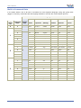
Technical specifications
Physical dimensions and pin assignment
Connector
J1
J2
J3
J4
Number
Name
Type
Description
1
GND
-
Ground
2
VCC
I
Voltage DC input
3
ERX
I
Serial Data Receive (TTL level)
4
ETX
O
Serial Data Transmit (TTL level)
1-2
PWM
O
Differential audio output (can directly drive 8Ω speaker)
1
MIC_RET
-
Microphone reference ground
2
MIC_IN
I
Microphone input signal
1
/RST
I
Active low asynchronous reset (internal 100K pull-up)
2
/XM
I
Boot select (internal 1K pull-down)
3
IO1
I/O
General purpose I/O (3.0 VDC TTL level)
4
IO2
I/O
General purpose I/O (3.0 VDC TTL level)
5
IO3
I/O
General purpose I/O (3.0 VDC TTL level)
Note: the GPIO (J4.3, J4.4, and J4.5) are at nominal 3.0VDC level. Do not connect 5VDC
directly to these pins!
User Manual (3.3)
EasyVR
5
www.veear.eu
Recommended Operating Conditions
Symbol
Min
Typ
Max
Unit
3.3
5.0
5.5
V
Ambient Operating Temperature Range
0
25
70
°C
ERX
Serial Port Receive Data
0
-
VCC
V
ETX
Serial Port Transmit Data
0
-
VCC
V
Min
Typ
Max
Unit
VCC
Parameter
Voltage DC Input
Ta
Electrical Characteristics
These are applicable to J4 pins only, including IO1-3, /XM and /RST.
Symbol
Parameter
VIH
Input High Voltage
2.4
3.0
3.3
V
VIL
Input Low Voltage
-0.1
0.0
0.75
V
IIL
Input Leakage Current (0 < VIO < 3V, Hi-Z Input)
<1
10
µA
Strong
10
kΩ
Weak
200
kΩ
RPU
Pull-up Resistance
VOH
Output High Voltage (IOH = -5 mA)
VOL
Output Low Voltage (IOL = 8 mA)
2.4
V
0.6
V
Power Supply Requirements
Symbol
Parameter
Min
Typ
Max
Unit
ISleep
Sleep current
<1
mA
IOper
Operating current
12
mA
Audio playback current (with 8Ω speaker)
180
mA (RMS)
ISpeaker
Serial Interface
The EasyVR is a “slave” module communicating via an asynchronous serial interface (commonly known as
UART interface), with the following features:
Baud Rate: 9600 (default), 19200, 38700, 57600, 115200
Frame: 8 Data bits, No parity, 1 Stop bit
The receiver input data line is ERX, while the transmitter output data line is ETX. No handshake lines are
used.
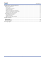
Example of a serial data frame representing character “A” (decimal 65 or hexadecimal 41):
VCC
Idle
Start
1
0
0
0
0
0
1
0
Stop
Idle
0V
See also chapter Communication Protocol later on this manual for communication details.
6
EasyVR
User Manual (3.3)
www.veear.eu
Microphone
The microphone provided with the EasyVR module is an omnidirectional electret condenser microphone
(Horn EM9745P-382):
Sensitivity -38dB (0dB=1V/Pa @1KHz)
Load Impedance 2.2K
Operating Voltage 3V
Almost flat frequency response in range 100Hz – 20kHz
If you use a microphone with different specifications the recognition accuracy may be adversely affected. No
other kind of microphone is supported by the EasyVR.
Note: Vocal commands should be given from about 60cm from the microphone, but you can try
at greater distances by talking louder.
Please note that improper acoustic positioning of the microphone will reduce recognition accuracy. Many
mechanical arrangements are possible for the microphone element, and some will work better than others.
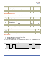
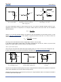
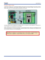
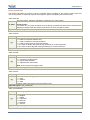
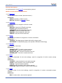
When mounting the microphone in the final device, keep in mind the following guidelines:
1. Flush Mounting - The microphone element should be positioned as close to the mounting surface
as possible and should be fully seated in the plastic housing. There must be no airspace between
the microphone element and the housing. Having such airspace can lead to acoustic resonance,
which can reduce recognition accuracy.
GOOD
BAD
cavity
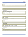
2. No Obstructions, Large Hole - The area in front of the microphone element must be kept clear of
obstructions to avoid interference with recognition. The diameter of the hole in the housing in front of
the microphone should be at least 5 mm. Any necessary plastic surface in front of the microphone
should be as thin as possible, being no more than 0.7 mm, if possible.
clear area
internal
diaphragm
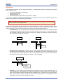
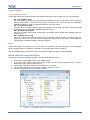
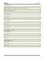
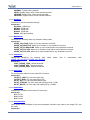
3. Insulation - The microphone should be acoustically isolated from the housing if possible. This can
be accomplished by surrounding the microphone element with a spongy material such as rubber or
foam. The provided microphone has this kind of insulating foam. The purpose is to prevent auditory
noises produced by handling or jarring the device from being “picked up” by the microphone. Such
extraneous noises can reduce recognition accuracy.
User Manual (3.3)
EasyVR
7
www.veear.eu
GOOD
BAD
absorbent
material
fastened
directly
4. Distance - If the microphone is moved from 15 cm to 30 cm from the speaker’s mouth, the signal
power decreases by a factor of four. The difference between a loud and a soft voice can also be
more than a factor of four. Although the internal preamplifier of the EasyVR compensates for a wide
dynamic range of input signal strength, if its range is exceeded, the user application can provide
feedback to the speaker about the voice volume (see appendix Error codes).
Audio Output
The EasyVR audio output interface is capable of directly driving an 8Ω speaker. It could also be connected to
an external audio amplifier to drive lower impedance loudspeakers.
Note: Connecting speakers with lower impedance directly to the module may permanently
damage the EasyVR audio output or the whole module.
It is possible to connect higher impedance loads such as headphones, provided that you scale down the
output power according to the speaker ratings, for example using a series resistor. The exact resistor value
depends on the headphone power ratings and the desired output volume (usually in the order of 10kΩ).
Note: Connecting headphone speakers directly to the EasyVR audio output may damage your
hearing.
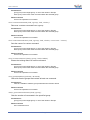
General Purpose I/O
Since the EasyVR communication interface takes two pins of the host controller, a few spare I/O pins are
provided, that can be controlled with the communication protocol, to get those pins back for basic tasks, such
as lighting an LED.
The three I/O pins IO1–IO3 are connected directly to the embedded microcontroller on the EasyVR module,
so they are referenced to the internal 3.0V regulated power supply. If you need to interface to circuits using a
different supply, there are a number of solutions you can adopt. Some of these are outlined below (here IOn
indicates any one of the three I/O pins of the EasyVR).
Use a pin as an output
All the I/O pins are inputs with weak internal pull-up after power on. You must explicitly configure a pin before
you can use it as an output (see the example code Use general purpose I/O pins).
8
EasyVR
User Manual (3.3)
www.veear.eu
5V
12V
IOn
AC MAINS
Voltage
RELAY
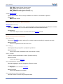
LED
Inverted
OUT
I/O pin directly driving a
low-current LED
Switched
Load
IOn
IOn
I/O pin connected to high
impedance 5V circuit (such as
MCU input pin)
I/O pin switching a load on a high voltage
line using a 12V relay
Z
-
The exact components values in these circuits may vary. You need to calculate required values for your
application and choice of components. For example, resistor value for the LED circuit can be calculated
approximately as:
Where VLED is the LED forward voltage, as reported on the LED datasheet, at the driving current IOH (see
section Electrical Characteristics). Let’s assume a typical low-current LED has a VF=1.8V at 5mA, the
resistor value is:
Now stay on the safe side and choose a slightly larger resistor, such as 150Ω.
If you want to drive higher current LEDs, you need a circuit like the second one, where you put the LED
between the output resistor and the collector of the NPN transistor.
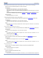
Use a pin as an input
All the I/O pins are inputs with weak internal pull-up after power on or reset. You may also configure the pin
to have a strong pull-up or no pull-up at all (see the example code Use general purpose I/O pins).
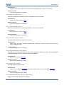
IOn
IOn
optional
filter
Isolated
IN
IOn
5V
IN
SWITCH
optocoupler
I/O pin connected to a switch
(or switching sensor)
I/O pin connected 5V source
(such as MCU output pin)
I/O pin with isolated input (for safety
circuits)
All these circuits assume the EasyVR pin has been configured with an internal pull-up (passive components
value can be adjusted to account for weak or strong pull-up).
Disabling the internal pull-up could be used to put the pin in high-impedance state, for example to simulate a
tri-state or open-drain output port.
User Manual (3.3)
EasyVR
9
www.veear.eu
Again, you should refer to the manufacturer’s datasheet when interfacing any external components and to
calculate required resistors values or other passive components.
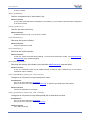
Flash Update
The EasyVR module includes a bootloader that allows to update the firmware and to download new sound
tables to the on-board memory.
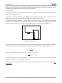
The boot mode is activated by keeping the /XM signal to a high logical level at power on or reset. This can be
easily done with a jumper (or switch) taking the signal to a suitable pull-up resistor.
To download a firmware update or a sound table to the EasyVR, power on the module with the jumper
closed. For normal operation, just leave the jumper open. Do not change the jumper position while the
module is already powered on. It is safe to change /XM level while the module is reset (/RST low).
VCC
/XM
Internal 1KΩ
Pull-down
Jumper
Boot mode selection circuit
The pull-up resistor value to use depends on the VCC power supply voltage. For the voltage of the /XM pin
when the jumper is closed (short) the following relation holds (note you have a voltage divider circuit):
Now if you want /XM to be at 3V (logic high) and solving for R, you get:
That makes 100Ω for 3.3V and around 680Ω for 5V power supplies. Other kinds of circuit are possible, that
is just an example and one of the simplest to realize.
To learn how to download new sound tables to your EasyVR module, have a look at the section Using
Sound Table.
10
EasyVR
User Manual (3.3)
www.veear.eu
Quick start for using the module
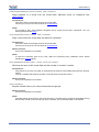
EasyVR on Arduino
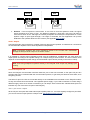
You can connect the EasyVR module to an Arduino board basically in two ways:
1. Bridge mode – You can control the module using a software serial library and connect to the
module with the EasyVR Commander from your PC, with the same pin configuration
2. Adapter mode – You can use the Arduino board as a USB/Serial adapter by holding the
microcontroller in reset, but you need to change the connections once you want to control the
module from the microcontroller
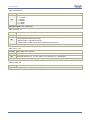
Bridge mode
This is the preferred connection mode, since it allows simple communication with both the Arduino
microcontroller and the PC. All the provided examples for Arduino manage the bridge mode automatically
when the EasyVR Commander requests a connection.
Arduino 2009
EasyVR Module
13 12
Blue
White
MIC
ETX
ERX
VCC
GND
Red
5V
GND
Black
Automatic bridge mode used to be supported only on Arduino boards with a bootloader implementing
EEPROM programming.
The latest version of EasyVR Commander (since 3.1.x) and Arduino libraries (since 1.1) does not rely on that
feature anymore, so it should work on all Arduino boards.
Note: bridge mode cannot be used to download a Sound Table or to perform a flash update.
You need to use adapter mode or a true USB/Serial adapter.
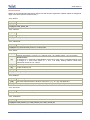
Adapter mode
This connection scheme has the advantage of working with any Arduino board that has an on-board
USB/Serial adapter and not needing a spare input pin to enter bridge mode.
Also, it does not rely on the AVR microcontroller to do any software bridge between communication pins, so
it can be used to check your hardware in case of connection problems.
Using this method also allows you to download a Sound Table to the EasyVR module, provided you also
configure the module to start in boot mode (see paragraph Flash Update).
User Manual (3.3)
EasyVR
11
www.veear.eu
Tx Rx
10
Arduino 2009/UNO/Mega
EasyVR Module
White
Blue
ETX
ERX
MIC
VCC
GND
Red
Reset
5V
GND
Black
Hold reset to use
as serial adapter
This configuration, with Reset shorted to GND, is for connection with the EasyVR Commander. To use the
module from the Arduino microcontroller, you need to remove the short (yellow wire) and move the ETX/ERX
connection to other pins. The example code uses pin 12 for ETX and pin 13 for ERX, like the above bridge
mode.
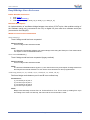
Arduino software
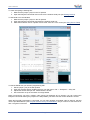
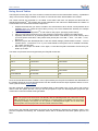
Follow these few steps to start playing with your EasyVR module and Arduino:
1.
2.
3.
4.
5.
Connect the EasyVR module to your Arduino board as outlined before
If you want audio output, connect an 8Ω speaker to J2 header
Connect the supplied microphone to the MIC (J3) connector
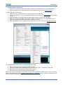
Copy the EasyVR library to your Arduino “libraries” folder on your PC
Connect your Arduino board to your PC via USB.
Figure 1 – Installation folder for the EasyVR Arduino library
12
EasyVR
User Manual (3.3)
www.veear.eu
To check everything is working fine:
1. Make sure you activate bridge mode (either manually or automatically) or you use adapter mode
2. Open the EasyVR Commander and connect to the Arduino serial port (see Getting Started)
To download a new sound-table:
1. Power OFF the EasyVR module (for example removing the USB cable)
2. Connect the /XM pin of J4 on the EasyVR module for boot mode (see Flash Update for a possible
circuit)
3. Power ON again the EasyVR module and the Arduino board (reconnect the USB cable)
4. Make sure you activate bridge mode (either manually or automatically) or you use adapter mode
5. Open the EasyVR Commander and select the Arduino serial port
6. While disconnected choose “Update Sound Table” from the “Tools” menu (see Using Sound Table)
To test the EasyVR module with your Arduino programming IDE:
1.
2.
3.
4.
Make sure you did not activate bridge mode manually
Open the example sketch TestEasyVR from your IDE menu “File” > “Examples” > “EasyVR”
Upload the sketch and open the “Serial Monitor” window
See comments on top of the sketch for usage details
When the EasyVR Commander is connected, you can also generate a template code for Arduino, that will
use the provided libraries (see EasyVR Arduino Library Documentation). All you need is to write actions for
each recognized command and adapt the code to your needs.
User Manual (3.3)
EasyVR
13
www.veear.eu
EasyVR on Robonova
With the robot switched off, connect the EasyVR module to the ROBONOVA controller board as in the
following diagram. Connect the microphone to the white MIC connector J2.
EasyVR Module
ROBONOVA-1 Controller Board
(MR-C3024)
Black
Red
GND
VCC
ERX
ETX
Blue
White
MIC
ETX
ERX
VCC
GND
The EasyVR Commander software can be used to easily connect the PC to the EasyVR module, without the
need of additional adapter boards, but simply by using the microcontroller host board with the provided
“bridge” program.
To start using the EasyVR Commander, connect the robot to your PC and turn on your ROBONOVA.
Select the serial port to use (the same as in RoboBasic Editor) from the toolbar or from the “File” menu, then
go with the “Connect” command.
Once connected to the robot, the EasyVR Commander software automatically downloads the RoboBasic
“bridge” program to the controller board, if not already present, and pass to its “programming” mode: you can
add and train new custom commands or change the language for built-in commands.
The “bridge” program, also has a “test” mode that allows the user to work with the robot and the set of built-in
commands the EasyVR module provides: once the bridge program has been downloaded to the robot
controller, you can disconnect the EasyVR Commander, detach the serial cable and immediately start using
the robot with the built-in vocal commands (see Built-in Command Sets).
For example, you can say "Robot" (the LED will turn on), then after a little pause say "Move" (wait for the
LED to blink), then say "Forward": the robot will take a short walk.
The EasyVR Commander can also generate a template RoboBasic code to help you start working with
custom commands. Once you have created and trained all your desired commands, you can generate the
basic template program by using the icon on the toolbar or the “File” menu.
Then disconnect EasyVR Commander, open the file with the RoboBasic Editor, make the required changes
to customize the behavior, and finally download and run it on the ROBONOVA controller.
Have fun!
Please note: the download of a sound table through the ROBONOVA controller board is not
supported, due to limitations of this hardware setup. You may use an USB/Serial adapter or
another bridge configuration to update the flash memory of the EasyVR module.
14
EasyVR
User Manual (3.3)
www.veear.eu
EasyVR on Basic Stamp
The EasyVR module can be connected to all Basic Stamp 2 series devices following the connection scheme
below. This is supported by the EasyVR Commander software with a special “bridge” code running on the
Basic Stamp, which can be downloaded automatically if not present.
EasyVR Module
Basic Stamp 2
Black
Red
VSS
VDD
ETX
ERX
VCC
GND
White
P0
Blue
P2
Status
LED
P4
MIC
The status LED is used to signal that a recognition task is in progress and the application is listening for a
voice command. This is optional and can be omitted.
When connected with the EasyVR Commander you can add and remove custom voice commands, as well
as train and test them. You can also generate a template PBASIC code to manage voice recognition, that
you can easily customize for your own application.
Please note: the download of a sound table through any Basic Stamp 2 controller board is not
supported, due to limitations of this hardware setup. You may use an USB/Serial adapter or
another suitable configuration to update the flash memory of the EasyVR module.
User Manual (3.3)
EasyVR
15
www.veear.eu
EasyVR Shield for Arduino
The EasyVR Shield is an Arduino shield integrating the EasyVR module, designed to simplify the EasyVR
management for all the Arduino developers.
Technical specifications
Physical dimensions and pin assignment
Connector
Number
Name
Type
Shield interface, same as on Arduino
(Pins 0-1 are in use when J12 is set as UP, PC or HW)
(Pins 12-13 are in use when J12 is set as SW)
J1, J2
J3, J4
J9
J10
J11
J13
Description
LINE OUT
O
3.5mm stereo/mono headphone jack (16Ω - 32Ω headphones)
1-2
SPEAKER
O
Differential audio output (can directly drive an 8Ω speaker)
1
MIC_IN
I
Microphone input signal
2
MIC_RET
-
Microphone reference ground
1
GND
-
Ground reference
2
IO1
I/O
General purpose I/O (3.0 VDC TTL level)
(Also used for on-board green LED D6)
3
IO2
I/O
General purpose I/O (3.0 VDC TTL level)
4
IO3
I/O
General purpose I/O (3.0 VDC TTL level)
Note: the GPIO (J13.2, J13.3, and J13.4) are at nominal 3.0VDC level. Do not connect 5VDC
directly to these pins!
16
EasyVR
User Manual (3.3)
www.veear.eu
Jumper settings
J12 – Operating mode
This jumper selects the operating mode of the EasyVR Shield and it can be placed in one of four positions:
o
o
o
o
UP – Flash update mode
Use it for firmware updates or to download sound table data to the on-board flash memory from the
EasyVR Commander. In this mode, the Arduino controller is held in reset and only the embedded
USB/Serial adapter is used. The EasyVR module is set in boot mode.
PC – PC connection mode
Use it for direct connection with the EasyVR Commander. In this mode, the Arduino controller is held
in reset and only the embedded USB/Serial adapter is used.
HW – Hardware serial mode
Use it for controlling the EasyVR module from your Arduino sketch through the hardware serial port
(using pins 0-1).
SW – Software serial mode
Use it for controlling the EasyVR module from your Arduino sketch through a software serial port
(using pins 12-13). You can also connect the EasyVR Commander in this mode, provided that the
running sketch implements bridge mode (see libraries).
LEDs
A green LED (D6) is connected to IO1 pin and can be controlled by the user’s program to show feedback
during recognition tasks, for example. This LED is on by default after reset or power up.
The red LED (D5) lights up when you set the shield to flash update mode (see Jumper settings).
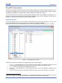
Quick start for using the Shield
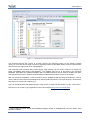
Follow these few steps to start playing with your EasyVR Shield and Arduino:
1. Insert the EasyVR Shield on top of your Arduino board
2. If you want audio output, either wire an 8Ω speaker into the screw terminals (J10) or connect
headphones to the 3.5mm output jack (J9)
3. Connect the supplied microphone to the MIC IN (J11) connector
4. Copy the EasyVR library to your Arduino “libraries” folder on your PC
5. Connect your Arduino board to your PC via USB.
Figure 2 – Installation folder for the EasyVR Arduino library
User Manual (3.3)
EasyVR
17
www.veear.eu
To check everything is working fine:
1. Make sure the jumper (J12) is in the PC position
2. Open the EasyVR Commander and connect to the Arduino serial port (see Getting Started)
To download a new sound-table:
1. Make sure the jumper (J12) is in the UP position
2. Open the EasyVR Commander and select the Arduino serial port
3. While disconnected choose “Update Sound Table” from the “Tools” menu (see Using Sound Table)
To test the Shield with your Arduino programming IDE:
1.
2.
3.
4.
Set the jumper (J12) in the SW position
Open the example sketch TestEasyVR from your IDE menu “File” > “Examples” > “EasyVR”
Upload the sketch and open the “Serial Monitor” window
See comments on top of the sketch for usage details
Keep in mind that if you have a “bridge” code running (all examples do) on Arduino, you can connect the
EasyVR Commander leaving the jumper in the SW position, just make sure the monitor window is closed.
When the EasyVR Commander is connected, you can also generate a template code for Arduino, that will
use the provided libraries (see EasyVR Arduino Library Documentation). All you need is to write actions for
each recognized command.
18
EasyVR
User Manual (3.3)
www.veear.eu
EasyVR Programming
Communication Protocol
Introduction
Communication with the EasyVR module uses a standard UART interface compatible with 3.3-5V
TTL/CMOS logical levels, according to the powering voltage VCC.
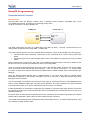
A typical connection to an MCU-based host:
EasyVR
Host MCU
3.3V – 5V
GND
TX
RX
VCC
GND
ERX
ETX
The initial configuration at power on is 9600 baud, 8 bit data, No parity, 1 bit stop. The baud rate can be
changed later to operate in the range 9600 - 115200 baud.
The communication protocol only uses printable ASCII characters, which can be divided in two main groups:
Command and status characters, respectively on the TX and RX lines, chosen among lower-case
letters.
Command arguments or status details, again on the TX and RX lines, spanning the range of capital
letters.
Each command sent on the TX line, with zero or more additional argument bytes, receives an answer on the
RX line in the form of a status byte followed by zero or more arguments.
There is a minimum delay before each byte sent out from the EasyVR module to the RX line, that is initially
set to 20 ms and can be selected later in the ranges 0 - 9 ms, 10 - 90 ms, and 100 ms - 1 s. That accounts
for slower or faster host systems and therefore suitable also for software-based serial communication (bitbanging).
Since the EasyVR serial interface also is software-based, a very short delay might be needed before
transmitting a character to the module, especially if the host is very fast, to allow the EasyVR to get back
listening to a new character.
The communication is host-driven and each byte of the reply to a command has to be acknowledged by the
host to receive additional status data, using the space character. The reply is aborted if any other character
is received and so there is no need to read all the bytes of a reply if not required.
Invalid combinations of commands or arguments are signaled by a specific status byte, that the host should
be prepared to receive if the communication fails. Also a reasonable timeout should be used to recover from
unexpected failures.
If the host does not send all the required arguments of a command, the command is ignored by the module,
without further notification, and the host can start sending another command.
The module automatically goes to lowest power sleep mode after power on. To initiate communication, send
any character to wake-up the module.
User Manual (3.3)
EasyVR
19
www.veear.eu
Arguments Mapping
Command or status messages sent over the serial link may have one or more numerical arguments in the
range -1 to 31, which are encoded using mostly characters in the range of uppercase letters. These are
some useful constants to handle arguments easily:
ARG_MIN
'@' (40h)
Minimum argument value (-1)
ARG_MAX
'`' (60h)
Maximum argument value (+31)
ARG_ZERO
'A' (41h)
Zero argument value (0)
ARG_ACK
' ' (20h)
Read more status arguments
Having those constants defined in your code can simplify the validity checks and the encoding/decoding
process. For example (in pseudo-code):
# encode value 5
FIVE = 5 + ARG_ZERO
# decode value 5
FIVE – ARG_ZERO = 5
# validity check
IF ARG < ARG_MIN OR ARG > ARG_MAX THEN ERROR
Just to make things clearer, here is a table showing how the argument mapping works:
ASCII
'@'
'A'
'B'
'C'
...
'Y'
'Z'
'^'
'['
'\'
']'
'_'
'`'
HEX
40
41
42
43
...
59
5A
5B
5C
5D
5E
5F
60
Value
-1
0
1
2
...
24
25
26
27
28
29
30
31
20
EasyVR
User Manual (3.3)
www.veear.eu
Command Details
This section describes the format of all the command strings accepted by the module. Please note that
numeric arguments of command requests are mapped to upper-case letters (see above section).
CMD_BREAK
Abort recognition, training or playback in progress if any or do nothing
'b' (62h)
Known issues:
In firmware ID 0, any other character received during recognition will prevent this command from
stopping recognition that will continue until timeout or other recognition results.
Expected replies: STS_SUCCESS, STS_INTERR
CMD_SLEEP
's' (73h)
Go to the specified power-down mode
Sleep mode (0-8):
0 = wake on received character only
1 = wake on whistle or received character
[1]
2 = wake on loud sound or received character
3-5 = wake on double clap (with varying sensitivity) or received character
6-8 = wake on triple clap (with varying sensitivity) or received character
Expected replies: STS_SUCCESS, STS_AWAKEN
CMD_KNOB
'k' (6Bh)
[1]
Set SI knob to specified level
Confidence threshold level (0-4):
0 = loosest:more valid results
2 = typical value (default)
4 = tightest:fewer valid results
Note: knob is ignored for trigger words
Expected replies: STS_SUCCESS
CMD_LEVEL
'v' (76h)
Set SD level
Strictness control setting (1-5):
1 = easy
[1]
2 = default
5 = hard
A higher setting will result in more recognition errors.
Expected replies: STS_SUCCESS
CMD_LANGUAGE
'l' (6Ch)
Set SI language
Language:
0 = English
1 = Italian
[1]
2 = Japanese
3 = German
4 = Spanish
5 = French
Expected replies: STS_SUCCESS
User Manual (3.3)
EasyVR
21
www.veear.eu
CMD_TIMEOUT
'o' (6Fh)
[1]
Set recognition timeout
Timeout (-1 = default, 0 = infinite, 1-31 = seconds)
Expected replies: STS_SUCCESS
CMD_RECOG_SI
'i' (69h)
[1]
Activate SI recognition from specified word set
Word set index (0-3)
Expected replies: STS_SIMILAR, STS_TIMEOUT, STS_ERROR
CMD_TRAIN_SD
't' (74h)
Train specified SD/SV command
[1]
Group index (0 = trigger, 1-15 = generic, 16 = password)
[2]
Command position (0-31)
Expected replies: STS_SUCCESS, STS_RESULT, STS_SIMILAR, STS_TIMEOUT, STS_ERROR
CMD_GROUP_SD
'g' (67h)
Insert new SD/SV command
[1]
Group index (0 = trigger, 1-15 = generic, 16 = password)
[2]
Position (0-31)
Expected replies: STS_SUCCESS, STS_OUT_OF_MEM
CMD_UNGROUP_SD
'u' (75h)
Remove SD/SV command
[1]
Group index (0 = trigger, 1-15 = generic, 16 = password)
[2]
Position (0-31)
Expected replies: STS_SUCCESS
CMD_RECOG_SD
'd' (64h)
[1]
Activate SD/SV recognition
Group index (0 = trigger, 1-15 = generic, 16 = password)
Expected replies: STS_RESULT, STS_SIMILAR, STS_TIMEOUT, STS_ERROR
CMD_ERASE_SD
'e' (65h)
Erase training of SD/SV command
[1]
Group index (0 = trigger, 1-15 = generic, 16 = password)
[2]
Command position (0-31)
Expected replies: STS_SUCCESS
22
EasyVR
User Manual (3.3)
www.veear.eu
CMD_NAME_SD
'n' (6Eh)
Label SD/SV command
[1]
Group index (0 = trigger, 1-15 = generic, 16 = password)
[2]
Command position (0-31)
[3]
Length of label (0-31)
[4-n]
Text for label (ASCII characters from 'A' to '`')
Expected replies: STS_SUCCESS
CMD_COUNT_SD
'c' (63h)
[1]
Request count of SD/SV commands in the specified group
Group index (0 = trigger, 1-15 = generic, 16 = password)
Expected replies: STS_COUNT
CMD_DUMP_SD
'p' (70h)
Read SD/SV command data (label and training)
[1]
Group index (0 = trigger, 1-15 = generic, 16 = password)
[2]
Command position (0-31)
Expected replies: STS_DATA
CMD_MASK_SD
'm' (6Dh)
Request bit-mask of non-empty groups
Expected replies: STS_MASK
CMD_RESETALL
'r' (72h)
Reset all commands and groups
'R' (52h)
Confirmation character
Expected replies: STS_SUCCESS
CMD_ID
'x' (78h)
Request firmware identification
Expected replies: STS_ID
CMD_DELAY
'y' (79h)
[1]
Set transmit delay
Time (0-10 = 0-10 ms, 11-19 = 20-100 ms, 20-28 = 200-1000 ms)
Expected replies: STS_SUCCESS
User Manual (3.3)
EasyVR
23
www.veear.eu
CMD_BAUDRATE
'a' (61h)
Set communication baud-rate
Speed mode:
1 = 115200
2 = 57600
[1]
3 = 38400
6 = 19200
12 = 9600
Expected replies: STS_SUCCESS
CMD_QUERY_IO
'q' (71h)
Configure, query or modify general purpose I/O pins
[1]
Pin number (1 = pin IO1, 2 = pin IO2, 3 = pin IO3)
Pin mode (0 = output low, 1 = output high, 2 = input*, 3 = input strong**, 4 = input weak***)
* High impedance input (no pull-up)
[2]
**Strong means ~10K internal pull-up
***Weak means ~200K internal pull-up (default after power up)
Expected replies: STS_SUCCESS (mode 0-1), STS_PIN (mode 2-4)
CMD_PLAY_SX
'w' (77h)
[1-2]
[3]
Wave table entry playback
Two 5-bit values that form a 10-bit index to the sound table (index = [1] * 32 + [2])
Playback volume (0-31, 0 = min volume, 15 = full scale, 31 = double gain)
Expected replies: STS_SUCCESS, STS_ERROR
CMD_DUMP_SX
'h' (68h)
Read wave table data
Expected replies: STS_TABLE_SX, STS_OUT_OF_MEM
24
EasyVR
User Manual (3.3)
www.veear.eu
Status Details
Replies to commands follow this format. Please note that numeric arguments of status replies are mapped to
upper-case letters (see the related section).
STS_MASK
'k' (6Bh)
[1-8]
Mask of non-empty groups
4-bit values that form 32-bit mask, LSB first
In reply to: CMD_MASK_SD
STS_COUNT
'c' (63h)
[1]
Count of commands
Integer (0-31)
In reply to: CMD_COUNT_SD
STS_AWAKEN
'w' (77h)
Wake-up (back from power-down mode)
In reply to: Any character after power on or sleep mode
STS_DATA
'd' (64h)
[2]
Provide command data
Training information (-1=empty, 1-6 = training count, +8 = SD/SV conflict, +16 = SI conflict)
Known issues:
In firmware ID 0, command creation/deletion might cause other empty commands training count
to change to 7. Treat count values of -1, 0 or 7 as empty training markers. Never train
commands more than 2 or 3 times.
Conflicting command position (0-31, only meaningful when trained)
[3]
Length of label (0-31)
[1]
[4-n]
Text of label (ASCII characters from 'A' to '`')
In reply to: CMD_DUMP_SD
STS_ERROR
'e' (65h)
[1-2]
Signal recognition error
Two 4-bit values that form 8-bit error code (error = [1] * 16 + [2], see appendix)
In reply to: CMD_RECOG_SI, CMD_RECOG_SD, CMD_TRAIN_SD, CMD_PLAY_SX
STS_INVALID
'v' (76h)
Invalid command or argument
In reply to: Any invalid command or argument
STS_TIMEOUT
't' (74h)
Timeout expired
In reply to: CMD_RECOG_SI, CMD_RECOG_SD, CMD_TRAIN_SD
User Manual (3.3)
EasyVR
25
www.veear.eu
STS_INTERR
'i' (69h)
Interrupted recognition
In reply to: CMD_BREAK while in training, recognition or playback
STS_SUCCESS
'o' (6Fh) OK or no errors status
In reply to: CMD_BREAK, CMD_DELAY, CMD_BAUDRATE, CMD_TIMEOUT, CMD_KNOB, CMD_LEVEL,
CMD_LANGUAGE, CMD_SLEEP, CMD_GROUP_SD, CMD_UNGROUP_SD, CMD_ERASE_SD,
CMD_NAME_SD, CMD_RESETALL, CMD_QUERY_IO, CMD_PLAY_SX
STS_RESULT
'r' (72h)
[1]
Recognized SD/SV command or Training similar to SD/SV command
Command position (0-31)
In reply to: CMD_RECOG_SD, CMD_TRAIN_SD
STS_SIMILAR
's' (73h)
[1]
Recognized SI word or Training similar to SI word
Word index (0-31)
In reply to: CMD_RECOG_SI, CMD_RECOG_SD, CMD_TRAIN_SD
STS_OUT_OF_MEM
'm' (6Dh)
Memory error (no more room for commands or sound table not present)
In reply to: CMD_GROUP_SD, CMD_DUMP_SX
STS_ID
'x' (78h)
[1]
Provide firmware identification
Version identifier (0)
In reply to: CMD_ID
STS_PIN
'p' (70h)
[1]
Provide pin input status
Logic level (0 = input low, 1 = input high)
In reply to: CMD_QUERY_IO
STS_TABLE_SX
'd' (64h)
[1-2]
[3]
[4-n]
Provide sound table data
Two 5-bit values that form a 10-bit count of entries in the sound table (count = [1] * 32 + [2])
Length of table name (0-31)
Text of table name (ASCII characters from 'A' to '`')
In reply to: CMD_DUMP_SX
26
EasyVR
User Manual (3.3)
www.veear.eu
Communication Examples
These are some examples of actual command and status strings exchanged with the EasyVR module by
host programs and the expected program flow with pseudo-code sequences.
The pseudo-instruction SEND transmits the specified character to the module, while RECEIVE waits for a
reply character (a timeout is not explicitly handled for simple commands, but should be always implemented
if possible).
Also, the OK and ERROR routines are not explicitly defined, since they are host and programming language
dependent, but appropriate code should be written to handle both conditions.
Lines beginning with a # (sharp) character are comments.
Please note that in a real programming language it would be best to define some constants for the command
and status characters, as well as for mapping numeric arguments, that would be used throughout the
program, to minimize the chance of repetition errors and clarify the meaning of the code.
See the Protocol header file for sample definitions that can be used in a C language environment.
Here below all the characters sent and received are written explicitly in order to clarify the communication
protocol detailed in the previous sections.
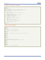
Recommended wake up procedure
# wake up or interrupt recognition or do nothing
# (uses a timeout or max repetition count)
DO
SEND 'b'
LOOP UNTIL RECEIVE = 'o'
Recommended setup procedure
# ask firmware id
SEND 'x'
IF NOT RECEIVE = 'x' THEN ERROR
# send ack and read status (expecting id=0)
SEND ' '
id = RECEIVE
IF id = 'A' THEN
# it’s a VRbot
ELSE IF id = 'B' THEN
# it’s an EasyVR
ELSE
# next generation?
END IF
# set language for SI recognition (Japanese)
SEND 'l'
SEND 'C'
IF RECEIVE = 'o' THEN OK ELSE ERROR
# set timeout (5 seconds)
SEND 'o'
SEND 'F'
IF RECEIVE = 'o' THEN OK ELSE ERROR
User Manual (3.3)
EasyVR
27
www.veear.eu
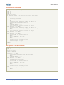
Recognition of a built-in SI command
# start recognition in wordset 1
SEND 'i'
SEND 'B'
# wait for reply:
# (if 5s timeout has been set, wait for max 6s then abort
# otherwise trigger recognition could never end)
result = RECEIVE
IF result = 's' THEN
# successful recognition, ack and read result
SEND ' '
command = RECEIVE – 'A'
# perform actions according to command
ELSE IF result = 't' THEN
# timed out, no word spoken
ELSE IF result = 'e' THEN
# error code, ack and read which one
SEND ' '
error = (RECEIVE – 'A') * 16
SEND ' '
error = error + (RECEIVE – 'A')
# perform actions according to error
ELSE
# invalid request or reply
ERROR
END IF
Adding a new SD command
# insert command 0 in group 3
SEND 'g'
SEND 'D'
SEND 'A'
IF RECEIVE = 'o' THEN OK ELSE ERROR
# set command label to “ARDUINO_2009”
SEND 'g'
SEND 'D'
SEND 'A'
SEND 'Q'
# name length (16 characters, digits count twice)
SEND 'A'
SEND 'R'
SEND 'D'
SEND 'U'
SEND 'I'
SEND 'N'
SEND 'O'
SEND '_'
# encode each digit with a ^ prefix
# followed by the digit mapped to upper case letters
SEND '^'
SEND 'C'
SEND '^'
SEND 'A'
SEND '^'
SEND 'A'
SEND '^'
SEND 'J'
IF RECEIVE = 'o' THEN OK ELSE ERROR
28
EasyVR
User Manual (3.3)
www.veear.eu
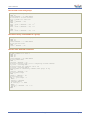
Training an SD command
# repeat the whole training procedure twice for best results
# train command 0 in group 3
SEND 't'
SEND 'D'
SEND 'A'
# wait for reply:
# (default timeout is 3s, wait for max 1s more then abort)
result = RECEIVE
IF RECEIVE = 'o' THEN
# training successful
OK
ELSE IF result = 'r' THEN
# training saved, but spoken command is similar to
# another SD command, read which one
SEND ' '
command = RECEIVE – 'A'
# may notify user and erase training or keep it
ELSE IF result = 's' THEN
# training saved, but spoken command is similar to
# another SI command (always trigger, may skip reading)
SEND ' '
command = RECEIVE – 'A'
# may notify user and erase training or keep it
ELSE IF result = 't' THEN
# timed out, no word spoken or heard
ELSE IF result = 'e' THEN
# error code, ack and read which one
SEND ' '
error = (RECEIVE – 'A') * 16
SEND ' '
error = error + (RECEIVE – 'A')
# perform actions according to error
ELSE
# invalid request or reply
ERROR
END IF
Recognition of an SD command
# start recognition in group 1
SEND 'd'
SEND 'B'
# wait for reply:
result = RECEIVE
IF result = 'r' THEN
# successful recognition, ack and read result
SEND ' '
command = RECEIVE – 'A'
# perform actions according to command
ELSE IF result = 't' THEN
# timed out, no word spoken
ELSE IF result = 'e' THEN
# error code, ack and read which one
SEND ' '
error = (RECEIVE – 'A') * 16
SEND ' '
error = error + (RECEIVE – 'A')
# perform actions according to error
ELSE
# invalid request or reply
ERROR
END IF
User Manual (3.3)
EasyVR
29
www.veear.eu
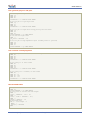
Read used command groups
# request mask of groups in use
SEND 'm'
IF NOT RECEIVE = 'k' THEN ERROR
# read mask to 32 bits variable
# in 8 chunks of 4 bits each
SEND ' '
mask = (RECEIVE – 'A')
SEND ' '
mask = mask + (RECEIVE – 'A') * 24
SEND ' '
mask = mask + (RECEIVE – 'A') * 28
...
SEND ' '
mask = mask + (RECEIVE – 'A') * 224
Read how many commands in a group
# request command count of group 3
SEND 'c'
SEND 'D'
IF NOT RECEIVE = 'c' THEN ERROR
# ack and read count
SEND ' '
count = RECEIVE - 'A'
Read a user defined command
# dump command 0 in group 3
SEND 'p'
SEND 'D'
SEND 'A'
IF NOT RECEIVE = 'd' THEN ERROR
# read command data
SEND ' '
training = RECEIVE – 'A'
# extract training count (2 for a completely trained command)
tr_count = training AND 7
# extract flags for conflicts (SD or SI)
tr_flags = training AND 24
# read index of conflicting command (same group) if any
SEND ' '
conflict = RECEIVE – 'A'
# read label length
SEND ' '
length = RECEIVE – 'A'
# read label text
FOR i = 0 TO length - 1
SEND ' '
label[i] = RECEIVE
# decode digits
IF label[i] = '^' THEN
SEND ' '
label[i] = RECEIVE – 'A' + '0'
END IF
NEXT
30
EasyVR
User Manual (3.3)
www.veear.eu
Use general purpose I/O pins
# set IO1 pin to logic low level
SEND 'q'
SEND 'B'
SEND 'A'
IF RECEIVE = 'o' THEN OK ELSE ERROR
# set IO2 pin to logic high level
SEND 'q'
SEND 'C'
SEND 'B'
IF RECEIVE = 'o' THEN OK ELSE ERROR
# set IO2 pin as input with strong pull-up and read state
SEND 'q'
SEND 'C'
SEND 'D'
IF NOT RECEIVE = 'p' THEN ERROR
# ack and read logic level
SEND ' '
pin_level = RECEIVE – 'A'
# set IO3 pin as high impedance input (reading state is optional)
SEND 'q'
SEND 'D'
SEND 'C'
IF NOT RECEIVE = 'p' THEN ERROR
Use custom sound playback
# play a beep at full volume (works with any or no table)
SEND 'w'
SEND 'A'
SEND 'A'
SEND 'P'
IF RECEIVE = 'o' THEN OK ELSE ERROR
# play entry 13 at half volume
SEND 'w'
SEND 'A'
SEND 'N'
SEND 'H'
IF RECEIVE = 'o' THEN OK ELSE ERROR
# play entry 123 (=3*32+26) at max volume
SEND 'w'
SEND 'A' + 3
SEND 'A' + 26
SEND 'A' + 31
IF RECEIVE = 'o' THEN OK ELSE ERROR
Read sound table
# dump sound table
SEND 'h'
IF NOT RECEIVE = 'h' THEN ERROR
# read count of entries and name length
SEND ' '
count = (RECEIVE – 'A') * 32
SEND ' '
count = count + (RECEIVE – 'A')
SEND ' '
length = RECEIVE – 'A'
# read name text
FOR i = 0 TO length - 1
SEND ' '
label[i] = RECEIVE
NEXT
User Manual (3.3)
EasyVR
31
www.veear.eu
Built-in Command Sets
In the tables below a list of all built-in commands for each supported language, along with group index
(trigger or word set), command index and language identifier to use with the communication protocol.
Language
0
Trigger
Word
set
0
1
2
3
32
1
Command English
Italian
Index
(US)
2
3
4
5
Japanese
(Rōmaji)
German
Spanish
French
0
robot
robot
ロボット
robotto
roboter
robot
robot
0
action
azione
アクション
acution
aktion
acción
action
1
move
vai
進め
susu-me
gehe
muévete
bouge
2
turn
gira
曲がれ
magare
wende
gira
tourne
3
run
corri
走れ
hashire
lauf
corre
cours
4
look
guarda
見ろ
miro
schau
mira
regarde
5
attack
attacca
攻撃
kougeki
attacke
ataca
attaque
6
stop
fermo
止まれ
tomare
halt
para
arrête
7
hello
ciao
こんにちは
konnichiwa
hallo
hola
salut
0
left
a sinistra
左
hidari
nach links
a la izquierda
à gauche
1
right
a destra
右
migi
nach rechts
a la derecha
à droite
2
up
in alto
上
ue
hinauf
arriba
vers le
haut
3
down
in basso
下
shita
hinunter
abajo
vers le bas
4
forward
avanti
前
mae
vorwärts
adelante
en avant
5
backward indietro
後ろ
ushiro
rückwärts
atrás
en arrière
0
zero
zero
ゼロ
zero
null
cero
zéro
1
one
uno
一
ichi
eins
uno
un
2
two
due
二
ni
zwei
dos
deux
3
three
tre
三
san
drei
tres
trois
4
four
quattro
四
yon
vier
cuatro
quatre
5
five
cinque
五
go
fünf
cinco
cinq
6
six
sei
六
roku
sechs
seis
six
7
seven
sette
七
nana
sieben
siete
sept
8
eight
otto
八
hachi
acht
ocho
huit
9
nine
nove
九
kyu
neun
nueve
neuf
10
ten
dieci
十
jyuu
zehn
diez
dix
EasyVR
User Manual (3.3)
www.veear.eu
Error codes
Below the list of the most useful error codes that may be returned by training or recognizing commands.
03h
ERR_DATACOL_TOO_NOISY
too noisy
04h
ERR_DATACOL_TOO_SOFT
spoke too soft
05h
ERR_DATACOL_TOO_LOUD
spoke too loud
06h
ERR_DATACOL_TOO_SOON
spoke too soon
07h
ERR_DATACOL_TOO_CHOPPY
too many segments/too complex
11h
ERR_RECOG_FAIL
recognition failed
12h
ERR_RECOG_LOW_CONF
recognition result doubtful
13h
ERR_RECOG_MID_CONF
recognition result maybe
14h
ERR_RECOG_BAD_TEMPLATE
invalid SD/SV command stored in memory
17h
ERR_RECOG_DURATION
bad pattern durations
4Ah
ERR_SYNTH_BAD_VERSION
bad release number in speech file
4Eh
ERR_SYNTH_BAD_MSG
bad data in speech file or invalid compression
80h
ERR_NOT_A_WORD
recognized word is not in vocabulary
The first group of codes (03h – 07h) is due to errors in the way of speaking to the EasyVR or disturbances in
the acquired audio signal that may depend on the surrounding environment.
The second group (11h – 13h) indicates an insufficient score of the recognized word (from lowest to highest).
Acceptance of lower score results may be allowed by lowering the “knob” or “level” settings, respectively for
built-in and custom commands (see CMD_KNOB and CMD_LEVEL).
A third group of codes (14h – 17h) reports errors in the stored commands that may be due to memory
corruption. We suggest you check power level and connections, then erase all the commands in the faulty
group and train them again.
The fourth group (4Ah – 4Eh) deals with errors in the compressed sound data, either because the wrong
TM
version of the QuickSynthesis tool has been used to generate the sound table or because a not supported
compression scheme has been selected (or data is generically corrupt).
The last code (80h) means that a word has been recognized that is not in the specified built-in sets. This is
due to how Speaker Independent recognition works and should be ignored.
User Manual (3.3)
EasyVR
33
www.veear.eu
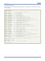
Protocol header file
This file “protocol.h” can be used with applications written in the C language. You can download a copy from
the VeeaR website.
#ifndef PROTOCOL_H
#define PROTOCOL_H
#define
#define
#define
#define
#define
#define
#define
#define
#define
#define
#define
#define
#define
#define
#define
#define
#define
#define
#define
#define
#define
#define
#define
CMD_BREAK
CMD_SLEEP
CMD_KNOB
CMD_LEVEL
CMD_LANGUAGE
CMD_TIMEOUT
CMD_RECOG_SI
CMD_TRAIN_SD
CMD_GROUP_SD
CMD_UNGROUP_SD
CMD_RECOG_SD
CMD_ERASE_SD
CMD_NAME_SD
CMD_COUNT_SD
CMD_DUMP_SD
CMD_MASK_SD
CMD_RESETALL
CMD_ID
CMD_DELAY
CMD_BAUDRATE
CMD_QUERY_IO
CMD_PLAY_SX
CMD_DUMP_SX
'b'
's'
'k'
'v'
'l'
'o'
'i'
't'
'g'
'u'
'd'
'e'
'n'
'c'
'p'
'm'
'r'
'x'
'y'
'a'
'q'
'w'
'h'
//
//
//
//
//
//
//
//
//
//
//
//
//
//
//
//
//
//
//
//
//
//
//
abort recognition/playback or ping
go to power down
set si knob <1>
set sd level <1>
set si language <1>
set timeout <1>
do si recog from ws <1>
train sd command at group <1> pos <2>
insert new command at group <1> pos <2>
remove command at group <1> pos <2>
do sd recog at group <1> (0 = trigger mixed si/sd)
reset command at group <1> pos <2>
label command at group <1> pos <2> with length <3> name <4-n>
get command count for group <1>
read command data at group <1> pos <2>
get active group mask
reset all commands and groups
get version id
set transmit delay <1> (log scale)
set baud rate <1> (bit time, 1=>115200)
configure, read or write I/O pin <1> of type <2>
wave table entry <1-2> (10-bit) playback at volume <3>
dump wave table entries
#define
#define
#define
#define
#define
#define
#define
#define
#define
#define
#define
#define
#define
#define
#define
STS_MASK
STS_COUNT
STS_AWAKEN
STS_DATA
STS_ERROR
STS_INVALID
STS_TIMEOUT
STS_INTERR
STS_SUCCESS
STS_RESULT
STS_SIMILAR
STS_OUT_OF_MEM
STS_ID
STS_PIN
STS_TABLE_SX
'k'
'c'
'w'
'd'
'e'
'v'
't'
'i'
'o'
'r'
's'
'm'
'x'
'p'
'h'
//
//
//
//
//
//
//
//
//
//
//
//
//
//
//
mask of active groups <1-8>
count of commands <1>
back from power down mode
get training <1>, conflict <2>, label <3-35> (counted string)
signal error code <1-2>
invalid command or argument
timeout expired
back from aborted recognition (see 'break')
no errors status
recognized sd command <1> - training similar to sd <1>
recognized si <1> (in mixed si/sd) - training similar to si <1>
no more available commands (see 'group')
provide version id <1>
return pin state <1>
provide table count <1-2> (10-bit), name <3-35> (counted string)
// protocol arguments are in the range 0x40 (-1) to 0x60 (+31) inclusive
#define ARG_MIN
0x40
#define ARG_MAX
0x60
#define ARG_ZERO
0x41
#define ARG_ACK
0x20
// to read more status arguments
#endif //PROTOCOL_H
34
EasyVR
User Manual (3.3)
www.veear.eu
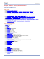
EasyVR Arduino Library Documentation
EasyVR Class Reference
Public Types
enum ModuleId { VRBOT, EASYVR }
enum Language { ENGLISH, ITALIAN, JAPANESE, GERMAN, SPANISH, FRENCH }
enum Group { TRIGGER, PASSWORD }
enum Wordset { TRIGGER_SET, ACTION_SET, DIRECTION_SET, NUMBER_SET }
enum Knob { LOOSER, LOOSE, TYPICAL, STRICT, STRICTER }
enum Level { EASY, NORMAL, HARD, HARDER, HARDEST }
enum Baudrate { B115200, B57600, B38400, B19200, B9600 }
enum WakeMode { WAKE_ON_CHAR, WAKE_ON_WHISTLE, WAKE_ON_LOUDSOUND,
WAKE_ON_2CLAPS, WAKE_ON_3CLAPS }
enum ClapSense { CLAP_SENSE_LOW, CLAP_SENSE_MID, CLAP_SENSE_HIGH }
enum PinConfig { OUTPUT_LOW, OUTPUT_HIGH, INPUT_HIZ, INPUT_STRONG, INPUT_WEAK }
enum PinNumber { IO1, IO2, IO3 }
enum SoundVolume { VOL_MIN, VOL_HALF, VOL_FULL, VOL_DOUBLE }
enum SoundIndex { BEEP }
Public Member Functions
EasyVR (Stream &s)
bool detect ()
bool stop ()
int8_t getID ()
bool setLanguage (int8_t lang)
bool setTimeout (int8_t seconds)
bool setKnob (int8_t knob)
bool setLevel (int8_t level)
bool setDelay (uint16_t millis)
bool changeBaudrate (int8_t baud)
bool sleep (int8_t mode)
bool addCommand (int8_t group, int8_t index)
bool removeCommand (int8_t group, int8_t index)
bool setCommandLabel (int8_t group, int8_t index, const char *name)
bool eraseCommand (int8_t group, int8_t index)
bool getGroupMask (uint32_t &mask)
int8_t getCommandCount (int8_t group)
bool dumpCommand (int8_t group, int8_t index, char *name, uint8_t &training)
void trainCommand (int8_t group, int8_t index)
void recognizeCommand (int8_t group)
void recognizeWord (int8_t wordset)
bool hasFinished ()
int8_t getCommand ()
int8_t getWord ()
int16_t getError ()
bool isTimeout ()
bool isConflict ()
bool isMemoryFull ()
bool setPinOutput (int8_t pin, int8_t value)
int8_t getPinInput (int8_t pin, int8_t config)
void playSoundAsync (int16_t index, int8_t volume)
bool playSound (int16_t index, int8_t volume)
bool dumpSoundTable (char *name, int16_t &count)
bool resetAll ()
User Manual (3.3)
EasyVR
35
www.veear.eu
Detailed Description
An implementation of the EasyVR communication protocol.
Member Enumeration Documentation
enum ModuleId
Module identification number (firmware version)
Enumerator:
VRBOT Identifies a VRbot module
EASYVR Identifies an EasyVR module
enum Language
Language to use for recognition of built-in words
Enumerator:
ENGLISH Uses the US English word sets
ITALIAN Uses the Italian word sets
JAPANESE Uses the Japanese word sets
GERMAN Uses the German word sets
SPANISH Uses the Spanish word sets
FRENCH Uses the French word sets
enum Group
Special group numbers for recognition of custom commands
Enumerator:
TRIGGER The trigger group (shared with built-in trigger word)
PASSWORD The password group (uses speaker verification technology)
enum Wordset
Index of built-in word sets
Enumerator:
TRIGGER_SET The built-in trigger word set
ACTION_SET The built-in action word set
DIRECTION_SET The built-in direction word set
NUMBER_SET The built-in number word set
enum Knob
Confidence thresholds for the knob settings, used for recognition of built-in words (except
trigger)
Enumerator:
LOOSER Lowest threshold, most results reported
LOOSE Lower threshold, more results reported
TYPICAL Typical threshold (deafult)
STRICT Higher threshold, fewer results reported
STRICTER Highest threshold, fewest results reported
enum Level
Strictness values for the level settings, used for recognition of custom commands (except
triggers)
Enumerator:
EASY Lowest value, most results reported
36
EasyVR
User Manual (3.3)
www.veear.eu
NORMAL Typical value (default)
HARD Slightly higher value, fewer results reported
HARDER Higher value, fewer results reported
HARDEST Highest value, fewest results reported
enum Baudrate
Constants to use for baudrate settings
Enumerator:
B115200 115200 bps
B57600 57600 bps
B38400 38400 bps
B19200 19200 bps
B9600 9600 bps (default)
enum WakeMode
Constants for choosing wake-up method in sleep mode
Enumerator:
WAKE_ON_CHAR Wake up on any character received
WAKE_ON_WHISTLE Wake up on whistle or any character received
WAKE_ON_LOUDSOUND Wake up on a loud sound or any character received
WAKE_ON_2CLAPS Wake up on double hands-clap or any character received
WAKE_ON_3CLAPS Wake up on triple hands-clap or any character received
enum ClapSense
Hands-clap sensitivity for wakeup from
WAKE_ON_2CLAPS or WAKE_ON_3CLAPS
sleep
mode.
Use
in
combination
with
Enumerator:
CLAP_SENSE_LOW Lowest threshold
CLAP_SENSE_MID Typical threshold
CLAP_SENSE_HIGH Highest threshold
enum PinConfig
Pin configuration options for the extra I/O connector
Enumerator:
OUTPUT_LOW Pin is a low output (0V)
OUTPUT_HIGH Pin is a high output (3V)
INPUT_HIZ Pin is an high impedance input
INPUT_STRONG Pin is an input with strong pull-up (~10K)
INPUT_WEAK Pin is an input with weak pull-up (~200K)
enum PinNumber
Available pin numbers on the extra I/O connector
Enumerator:
IO1 Pin IO1
IO2 Pin IO2
IO3 Pin IO3
enum SoundVolume
Some quick volume settings for the sound playback functions (any value in the range 0-31 can
be used)
Enumerator:
User Manual (3.3)
EasyVR
37
www.veear.eu
VOL_MIN Lowest volume (almost mute)
VOL_HALF Half scale volume (softer)
VOL_FULL Full scale volume (normal)
VOL_DOUBLE Double gain volume (louder)
enum SoundIndex
Special sound index values, always available even when no soundtable is present
Enumerator:
BEEP Beep sound
Constructor & Destructor Documentation
EasyVR (Stream & s)
Creates an EasyVR object, using a communication object implementing the Stream interface
(such as HardwareSerial, or the modified SoftwareSerial and NewSoftSerial).
Parameters:
s the Stream object to use for communication with the EasyVR module
Member Function Documentation
bool detect ()
Detects an EasyVR module, waking it from sleep mode and checking it responds correctly.
Return values:
is true if a compatible module has been found
bool stop ()
Interrupts pending recognition or playback operations.
Return values:
is true if the request is satisfied and the module is back to ready
int8_t getID ()
Gets the module identification number (firmware version).
Return values:
is one of the values in ModuleId
bool setLanguage (int8_t lang)
Sets the language to use for recognition of built-in words.
Parameters:
lang (0-5) is one of values in Language
Return values:
is true if the operation is successful
bool setTimeout (int8_t seconds)
Sets the timeout to use for any recognition task.
38
EasyVR
User Manual (3.3)
www.veear.eu
Parameters:
seconds (0-31) is the maximum time the module keep listening for a word or a command
Return values:
is true if the operation is successful
bool setKnob (int8_t knob)
Sets the confidence threshold to use for recognition of built-in words.
Parameters:
knob (0-4) is one of values in Knob
Return values:
is true if the operation is successful
bool setLevel (int8_t level)
Sets the strictness level to use for recognition of custom commands.
Parameters:
level (1-5) is one of values in Level
Return values:
is true if the operation is successful
bool setDelay (uint16_t millis)
Sets the delay before any reply of the module.
Parameters:
millis (0-1000) is the delay duration in milliseconds, rounded to 10 units in range 10-100 and to 100
units in range 100-1000.
Return values:
is true if the operation is successful
bool changeBaudrate (int8_t baud)
Sets the new communication speed. You need to modify the baudrate of the underlying Stream
object accordingly, after the function returns successfully.
Parameters:
baud is one of values in Baudrate
Return values:
is true if the operation is successful
bool sleep (int8_t mode)
Puts the module in sleep mode.
Parameters:
mode is one of values in WakeMode, optionally combined with one of the values in ClapSense
Return values:
is true if the operation is successful
bool addCommand (int8_t group, int8_t index)
Adds a new custom command to a group.
User Manual (3.3)
EasyVR
39
www.veear.eu
Parameters:
group (0-16) is the target group, or one of the values in Groups
index (0-31) is the index of the command within the selected group
Return values:
is true if the operation is successful
bool removeCommand (int8_t group, int8_t index)
Removes a custom command from a group.
Parameters:
group (0-16) is the target group, or one of the values in Groups
index (0-31) is the index of the command within the selected group
Return values:
is true if the operation is successful
bool setCommandLabel (int8_t group, int8_t index, const char * name)
Sets the name of a custom command.
Parameters:
group (0-16) is the target group, or one of the values in Groups
index (0-31) is the index of the command within the selected group
Return values:
is true if the operation is successful
bool eraseCommand (int8_t group, int8_t index)
Erases the training data of a custom command.
Parameters:
group (0-16) is the target group, or one of the values in Groups
index (0-31) is the index of the command within the selected group
Return values:
is true if the operation is successful
bool getGroupMask (uint32_t & mask)
Gets a bit mask of groups that contain at least one command.
Parameters:
mask is a variable to hold the group mask when the function returns
Return values:
is true if the operation is successful
int8_t getCommandCount (int8_t group)
Gets the number of commands in the specified group.
Parameters:
group (0-16) is the target group, or one of the values in Groups
Return values:
is the command count
40
EasyVR
User Manual (3.3)
www.veear.eu
bool dumpCommand (int8_t group, int8_t index, char * name, uint8_t & training)
Retrieves the name and training data of a custom command.
Parameters:
group (0-16) is the target group, or one of the values in Groups
index (0-31) is the index of the command within the selected group
name points to an array of at least 32 characters that holds the command label when the function
returns
training is a variable that holds the training count when the function returns. Additional information
about training is available through the functions isConflict() and getWord() or getCommand()
Return values:
is true if the operation is successful
void trainCommand (int8_t group, int8_t index)
Starts training of a custom command. Results are available after hasFinished() returns true.
Parameters:
group (0-16) is the target group, or one of the values in Groups
index (0-31) is the index of the command within the selected group
Note:
The module is busy until training completes and it cannot accept other commands. You can interrupt
training with stop().
void recognizeCommand (int8_t group)
Starts recognition of a custom command. Results are available after hasFinished() returns true.
Parameters:
group (0-16) is the target group, or one of the values in Groups
Note:
The module is busy until recognition completes and it cannot accept other commands. You can
interrupt recognition with stop().
void recognizeWord (int8_t wordset)
Starts recognition of a built-in word. Results are available after hasFinished() returns true.
Parameters:
wordset (0-3) is the target word set, or one of the values in Wordset
Note:
The module is busy until recognition completes and it cannot accept other commands. You can
interrupt recognition with stop().
bool hasFinished ()
Polls the status of on-going recognition, training or asynchronous playback tasks.
Return values:
is true if the operation has completed
int8_t getCommand ()
Gets the recognised command index if any.
Return values:
(0-31) is the command index if recognition is successful, (-1) if no command has been recognized or
User Manual (3.3)
EasyVR
41
www.veear.eu
an error occured
int8_t getWord ()
Gets the recognised built-in word index if any.
Return values:
(0-31) is the command index if recognition is successful, (-1) if no built-in word has been recognized
or an error occured
int16_t getError ()
Gets the last error code if any.
Return values:
(0-255) is the error code, (-1) if no error occured
bool isTimeout ()
Retrieves the timeout indicator.
Return values:
is true if a timeout occurred
bool isConflict ()
Retrieves the conflict indicator.
Return values:
is true is a conflict occurred during training. To know what caused the conflict, use getCommand()
and getWord() (only valid for triggers)
bool isMemoryFull ()
Retrieves the memory full indicator (only valid after addCommand() returned false).
Return values:
is true if a command could not be added because of memory size constaints (up to 32 custom
commands can be created)
bool setPinOutput (int8_t pin, int8_t value)
Configures an I/O pin as an output and sets its value
Parameters:
pin (1-3) is one of values in PinNumber
pin (0-1) is one of the output values in PinConfig, or Arduino style HIGH and LOW macros
Return values:
is true if the operation is successful
int8_t getPinInput (int8_t pin, int8_t config)
Configures an I/O pin as an input with optional pull-up and return its value
Parameters:
pin (1-3) is one of values in PinNumber
pin (2-4) is one of the input values in PinConfig
Return values:
is the value of the pin
42
EasyVR
User Manual (3.3)
www.veear.eu
void playSoundAsync (int16_t index, int8_t volume)
Starts playback of a sound from the sound table. Manually check for completion with
hasFinished().
Parameters:
index is the index of the target sound in the sound table
volume (0-31) may be one of the values in SoundVolume
Note:
The module is busy until playback completes and it cannot accept other commands. You can
interrupt playback with stop().
bool playSound (int16_t index, int8_t volume)
Plays a sound from the sound table and waits for completion
Parameters:
index is the index of the target sound in the sound table
volume (0-31) may be one of the values in SoundVolume
Return values:
is true if the operation is successful
Note:
To alter the maximum time for the wait, define the EASYVR_PLAY_TIMEOUT macro before
including the EasyVR library.
bool dumpSoundTable (char * name, int16_t & count)
Retrieves the name of the sound table and the number of sounds it contains
Parameters:
name points to an array of at least 32 characters that holds the sound table label when the function
returns
count is a variable that holds the number of sounds when the function returns
Return values:
is true if the operation is successful
bool resetAll ()
Empties internal memory for custom commands and groups.
Return values:
is true if the operation is successful
Note:
It will take about 35 seconds for the whole process to complete and it cannot be interrupted. During
this time the module cannot accept any other command. The sound table data is not affected.
User Manual (3.3)
EasyVR
43
www.veear.eu
EasyVRBridge Class Reference
Public Member Functions
bool check ()
bool checkEEPROM ()
void loop (uint8_t a_rx, uint8_t a_tx, uint8_t b_rx, uint8_t b_tx)
Detailed Description
An implementation of a software bridge between two series of Rx/Tx pins, that enables routing of
the hardware serial port (connected to the PC) to digital I/O pins used as a software serial port
(connected to the EasyVR).
Member Function Documentation
bool check ()
Tests if bridge mode has been requested
Return values:
is true if bridge mode should be started
Note:
The EasyVR Commander software can request bridge mode using the Serial port. This method does
not require to reserve EEPROM locations.
bool checkEEPROM ()
Tests if bridge mode has been requested (legacy method)
Return values:
is true if bridge mode should be started
Note:
The first two EEPROM locations (bytes 0-1) are used for discovery and request of bridge mode from
the EasyVR Commander software. Do not use the same locations for other programa data.
void loop (uint8_t a_rx, uint8_t a_tx, uint8_t b_rx, uint8_t b_tx)
Performs bridge mode between port A and B in an endless loop
Parameters:
a_rx is the Rx pin of port A
a_tx is the Tx pin of port A
b_rx is the Rx pin of port B
b_tx is the Tx pin of port B
Note:
Bridge mode internally connects Rx:A to Tx:B and Rx:B to Tx:A. This is done by reading from a pin
and writing to the other in a fast loop, that runs until the microcontroller is reset.
44
EasyVR
User Manual (3.3)
www.veear.eu
EasyVR Commander
The EasyVR Commander software can be used to easily configure your EasyVR module connected to your
PC through an adapter board, or by using the microcontroller host board with the provided “bridge” program
(available for ROBONOVA controller board, Arduino 2009/UNO, Parallax Basic Stamp).
You can define groups of commands or passwords and generate a basic code template to handle them. It is
required to edit the generated code to implement the application logic, but the template contains all the
functions or subroutines to handle the speech recognition tasks.
Getting Started
1
Connect the adapter board or a microcontroller host board with a running “bridge” program to your PC, and
then check that all devices are properly turned on and start the EasyVR Commander.
Select the serial port to use from the toolbar or the “File” menu, and then go with the “Connect” command.
Figure 3 – Main application window
There are four kinds of commands in the software (see Figure 3 and Figure 6):
Trigger - is a special group where you have the built-in SI trigger word "Robot" and you may add
one user-defined SD trigger word. Trigger words are used to start the recognition process
Group - where you may add user-defined SD commands
Password - a special group for "vocal passwords" (up to five), using Speaker Verification (SV)
technology
Wordset - built-in set of SI commands (for instance in Figure 3 above, the Wordset 1 is selected)
1
On some systems the EasyVR Commander can automatically upload the “bridge” program to the host
board once connected. That applies to Robonova controller board and Parallax Basic Stamp.
User Manual (3.3)
EasyVR
45
www.veear.eu
Speech Recognition
The recognition function of the EasyVR works on a single group at a time, so that users need to group
together all the commands that they want to be able to use at the same time.
When EasyVR Commander connects to the module, it reads back all the user-defined commands and
groups, which are stored into the EasyVR module non-volatile memory.
You can add a new command by first selecting the group in which the command needs to be created and
then using the toolbar icons or the “Edit” menu.
A command should be given a label and then it should be trained twice with the user's voice: the user will be
guided throughout this process (see Figure 4) when the "Train Command" action is invoked.
Figure 4 – Guided training dialog
Note: after clicking on Phase 1 or Phase 2 buttons, remember to start speaking only when you
see this little window:
If any error happens, command training will be cancelled. Errors may happen when the user’s voice is not
heard correctly, there is too much background noise or when the second word heard is too different from the
first one.
Figure 5 – Alert dialog in case of conflict
The software will also alert if a command is too similar to an existing one by specifying the index of the
conflicting command in the "Conflict" column. For example, in the following Figure 6 the command
46
EasyVR
User Manual (3.3)
www.veear.eu
"TEST_CMD_ONE" sounds too similar to "TEST_CMD_ZERO" (i.e. they have been trained with a similar
pronunciation).
Note: TEST_CMD_ZERO and TEST_CMD_ONE are just examples of labels, you should use
label names that reflects the real command that you are going to train.
Figure 6 – Conflicting commands
The current status is displayed in the EasyVR Commander list view where groups that already contain
commands are highlighted in bold.
The selected group of commands can also be tested, by using the icon on the toolbar or the “Tools” menu,
to make sure the trained commands can be recognized successfully.
Note: If you want to re-train a command you have to erase the previous training first.
Note: "Vocal passwords"(group 16) are much more sensitive to environment noise and distance
from the microphone: be sure to train and give the password in similar conditions
User Manual (3.3)
EasyVR
47
www.veear.eu
Using Sound Tables
The EasyVR can also play one of the sounds or sentences saved on the internal flash memory. A predefined
“beep” sound is also always available, even when no sounds have been downloaded to the module.
The custom sounds are organized in a so-called “sound table” that users can prepare and build with the
TM
special QuickSynthesis tool. Please refer to this application’s own manual for details about the creation of
a sound table. Let’s summarize the basic steps here:
Prepare the audio files you want to include in the sound table in WAV format, uncompressed 16-bit
22050Hz mono. To create the sound files you may use a free software like Audacity for example
(http://audacity.sf.net)
TM
Open Sensory’s QuickSynthesis 5 and create a new project, specifying “RSC4 family”
Add your WAV files and specify one of the supported compression scheme (see table below)
Optionally add sentences, by combining basic WAV sounds. That allows you to save memory when
you have speech audio files, if they share some pieces (like “You said” + “One”, “You said” + “Two”,
and so on)
TM
Build the project with QuickSynthesis and use default settings (“Build linkable module”, “Load in
CONST space”, “Load above or at: 0”). You will be asked to recompress new or modified sound files,
just confirm and proceed
Now save your project and build it once again, so that the EasyVR Commander will see that your
build is up to date.
The audio compression formats supported by the EasyVR module are:
Compression Scheme
Available Time (8kHz 15% silence)
Available Time (9.3kHz 15% silence)
SX-2
8.7 minutes
7.5 minutes
SX-3
7.6 minutes
6.6 minutes
SX-4
6.8 minutes
5.9 minutes
SX-5
6.1 minutes
5.2 minutes
SX-6
5.6 minutes
4.8 minutes
4-bit ADPCM
87 seconds
N/A
8-bit PCM
45 seconds
38 seconds
Once the sound table has been created, it can be processed by the EasyVR Commander and downloaded to
the module. Note that you must first disconnect from the module and do the steps required to start it in “bootmode” (see the section Flash Update).
Now the command “Update Sound Table” is enabled, either on the toolbar or the “Tools” menu, and it can be
used to start the update process. First you will be prompted to open the QuickSynthesis project file just
created and a new sound table will be generated.
Note: The project must have been built already with the QuickSynthesis tool, before the sound
table generation can be completed successfully. If a recent build is not available you will receive
a warning message, the project can be opened in QuickSynthesis again and a fresh build
started (make sure the project file has been saved before the build).
Once back in the EasyVR Commander the project can be reloaded by pressing the “Refresh” button. If the
process completes successfully, the “Download” button will be enabled and the flash update process can
start.
48
EasyVR
User Manual (3.3)
www.veear.eu
Figure 7 – Sound Table build and download interface
The download process will connect at a higher speed to the EasyVR module, so the “bridge” program
running on your host device might not work (in particular Robonova and Basic Stamp cannot be used for this
purpose) and you might need a true “serial adapter”.
The full speed used is 230400 bit/s, but the option “Slow transfer” can be used to reduce it to 115200, for
2
better compatibility with slower serial adapters . One adapter that can go to full speed is the SmartVR
DevBoard. Otherwise any USB/Serial adapter with TTL/CMOS interface can be used for updating the flash.
The EasyVR Shield can be used for the download, provided that the jumper (J12) is in UP position.
After the download completes, a new connection can be established with the EasyVR module (in “normalmode”) and the new sounds will be displayed by the EasyVR Commander, in the special group “SoundTable”
(the last one in the list with a yellow icon).
They can be played back and tested using the “Play Sound” command on the toolbar or in the “Tools” menu.
See also how to do that in your application in the code example Use custom sound playback.
2
Arduino UNO (and other boards with USB/Serial adapter based on ATMEGA8U2) need the option “Slow
transfers” enabled
User Manual (3.3)
EasyVR
49
www.veear.eu
How to get support
Please feel free to contact us with any questions, queries or suggestions.
If your question is about technical support or troubleshooting for one of our products, we kindly ask you to
first check our Forum for a possible solution: http://www.veear.eu
If you cannot find an existing solution on the forum, we strongly recommend posting your support request on
the forum for as quick a response as possible. The more detail you provide, the better support we can give.
50
EasyVR
User Manual (3.3)
www.veear.eu
VeeaR © TIGAL KG, all right reserved.
All VeeaR branded boards and software are manufactured by TIGAL KG. Made in Austria.
TIGAL KG assumes no responsibility for any errors, which may appear in this manual. Furthermore, TIGAL KG reserves
the right to alter the hardware, software, and/or specifications detailed herein at any time without notice, and does not
make any commitment to update the information contained herein. TIGAL KG products are not authorized for use as
critical components in life support devices or systems.
User Manual (3.3)
EasyVR
51