1
V-SERIES PANELS
User Guide
V-Series Panels Instruction Manual
© 2007 - 2010 Clear-Com, LLC. All rights reserved.
Part Number 810365Z Rev. 7
Clear-Com, LLC.
850 Marina Village Parkway
Alameda, CA 94501
U.S.A.
HME Clear-Com Ltd
7400 Beach Drive
IQ Cambridge
Cambridgeshire
United Kingdom
CB25 9TP
® Clear-Com, CellCom/FreeSpeak and the Clear-Com logo are registered trademarks of ClearCom, LLC.
Website: www.clearcom.com
IMPORTANT SAFETY
INSTRUCTIONS
Please read and follow these instructions before operating an Eclipse V-Series Panel.
Keep these instructions for future reference.
Please read and follow these
instructions before operating
a V-Series Panel
1. Read these instructions.
2. Keep these instructions.
3. Heed all warnings.
4. Follow all instructions.
5. Do not use this apparatus near water.
6. Clean only with dry cloth.
7. Do not block any ventilation openings. Install in accordance with the
manufacturer’s instructions.
8. Do not install near any heat sources such as radiators, heat
registers, stoves, or other apparatus (including amplifiers) that
produce heat.
9. Do not defeat the safety purpose of the polarized or grounding-type
plug. A polarized plug has two blades, with one blade wider than
the other. A grounding-type plug has two blades and a third
grounding prong. The wide blade or the third prong are provided for
your safety. If the provided plug does not fit into your outlet, consult
an electrician for replacement of the obsolete outlet.
10. Protect the power cord from being walked on or pinched
particularly at plugs, convenience receptacles, and the point where
they exit from the apparatus.
11. Only use attachments/accessories specified by the manufacturer.
12. Use only with the cart, stand, tripod, bracket, or table specified by
the manufacturer, or sold with the apparatus. When a cart is used,
use caution when moving the cart/apparatus combination to avoid
injury from tip-over.
13. Unplug this apparatus during lightning storms or when unused for
long periods of time.
14. Refer all servicing to qualified service personnel. Servicing is
required when the apparatus has been damaged in any way, such
as power-supply cord or plug is damaged, liquid has been spilled
or objects have fallen into the apparatus, the apparatus has been
exposed to rain or moisture, does not operate normally, or has
been dropped.
15. WARNING: To reduce the risk of fire or electric shock, do not
expose this product to rain or moisture.
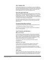
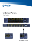
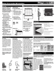
Please familiarize yourself with the safety symbols in Figure 1.
When you see these symbols on this product, they warn you of
the potential danger of electric shock if the main station is used
improperly. They also refer you to important operating and
maintenance instructions in the manual.
Clear-Com
V-Series Panels User Guide
i
CAUTION
RISK OF ELECTRIC SHOCK
DO NOT OPEN
This symbol alerts you to the presence of uninsulated dangerous
voltage within the product’s enclosure that might be of sufficient
magnitude to constitute a risk of electric shock. Do not open
the product’s case.
This symbol informs you that important operating and maintenance instructions are included in the literature accompanying
this product.
Figure 1: Safety Symbols
EMC AND SAFETY
The V-Series Panels meet all relevant CE, FCC, UL, and CSA
specifications set out below:
EN55103-1 Electromagnetic compatibility. Product family
standard for audio, video, audio-visual, and entertainment
lighting control apparatus for professional use. Part 1:
Emissions.
EN55103-2 Electromagnetic compatibility. Product family
standard for audio, video, audio-visual, and entertainment
lighting control apparatus for professional use. Part 2: Immunity.
UL 60065-7, CAN/CSA-C22.2 No.60065-3, IEC 60065-7 Safety
requirements.
And thereby compliance with the requirement of Electromagnetic
Compatibility Directive 2004/108/EC and Low Voltage Directive
2006/95/EC
This device complies with Part 15 of the FCC Rules. Operation is
subject to the following two conditions: (1) this device may not
cause harmful interference, and (2) this device must accept any
interference received, including interference that may cause
undesired operation.
ii
Clear-Com
V-Series Panels User Guide
CONTENTS
INTRODUCTION . . . . . . . . . . . . . . . . . . . . . . . . . . . 1-1
Description . . . . . . . . . . . . . . . . . . . . . . . . . . . . . . . . . . . . . . . . . . . . 1-1
V-Series Panels. . . . . . . . . . . . . . . . . . . . . . . . . . . . . . . . . . . . . . . 1-1
Lever Key Panels. . . . . . . . . . . . . . . . . . . . . . . . . . . . . . . . . . . . 1-1
Pushbutton Panels. . . . . . . . . . . . . . . . . . . . . . . . . . . . . . . . . . . 1-1
Rotary Control Panels . . . . . . . . . . . . . . . . . . . . . . . . . . . . . . . . 1-1
V-Series Panel Options . . . . . . . . . . . . . . . . . . . . . . . . . . . . . . . . . 1-2
Front-Panel Controls and Indicators . . . . . . . . . . . . . . . . . . . . . . . . . 1-2
Display Window. . . . . . . . . . . . . . . . . . . . . . . . . . . . . . . . . . . . . . . 1-7
Key Display . . . . . . . . . . . . . . . . . . . . . . . . . . . . . . . . . . . . . . . . . . 1-8
Reply Key Display . . . . . . . . . . . . . . . . . . . . . . . . . . . . . . . . . . . . 1-10
Fonts. . . . . . . . . . . . . . . . . . . . . . . . . . . . . . . . . . . . . . . . . . . . . . . . 1-11
Panel Operation . . . . . . . . . . . . . . . . . . . . . . . . . . . . . . . . . . . . . . . 1-11
MIC ON Button . . . . . . . . . . . . . . . . . . . . . . . . . . . . . . . . . . . . . . 1-11
Shift Page Button . . . . . . . . . . . . . . . . . . . . . . . . . . . . . . . . . . . . 1-12
Headset Select Button . . . . . . . . . . . . . . . . . . . . . . . . . . . . . . . . 1-12
Menu Button . . . . . . . . . . . . . . . . . . . . . . . . . . . . . . . . . . . . . . . . 1-12
Main Volume Control . . . . . . . . . . . . . . . . . . . . . . . . . . . . . . . . . . 1-12
Auxiliary Volume Control . . . . . . . . . . . . . . . . . . . . . . . . . . . . . . . 1-13
Listen Again Replay . . . . . . . . . . . . . . . . . . . . . . . . . . . . . . . . . . 1-13
Up/Down Volume Buttons . . . . . . . . . . . . . . . . . . . . . . . . . . . . . . 1-13
Rotary Encoder . . . . . . . . . . . . . . . . . . . . . . . . . . . . . . . . . . . . . . 1-14
Keypad (2RU & Desktop Panels) . . . . . . . . . . . . . . . . . . . . . . . . 1-14
PTT Operation. . . . . . . . . . . . . . . . . . . . . . . . . . . . . . . . . . . . . . . 1-15
Lever Key Panel Operation . . . . . . . . . . . . . . . . . . . . . . . . . . . . . 1-16
Lever Key Reply Key GPI Operation . . . . . . . . . . . . . . . . . . . . 1-16
Pushbutton Panel Operations . . . . . . . . . . . . . . . . . . . . . . . . . . . 1-16
Pushbutton Reply Key GPI Operation . . . . . . . . . . . . . . . . . . . 1-17
Rotary Panel Operations . . . . . . . . . . . . . . . . . . . . . . . . . . . . . . . 1-17
Key Operation . . . . . . . . . . . . . . . . . . . . . . . . . . . . . . . . . . . . . 1-17
Reply Key . . . . . . . . . . . . . . . . . . . . . . . . . . . . . . . . . . . . . . . . 1-18
COM Keys . . . . . . . . . . . . . . . . . . . . . . . . . . . . . . . . . . . . . . . . 1-18
Rotary Panel IFB Operation. . . . . . . . . . . . . . . . . . . . . . . . . . . 1-18
Rotary Forced Listen Operation. . . . . . . . . . . . . . . . . . . . . . . . 1-19
Rotary Panel Reply Key GPI Operation. . . . . . . . . . . . . . . . . . 1-19
Clear-Com
V-Series Panels User Guide
i
OPERATION . . . . . . . . . . . . . . . . . . . . . . . . . . . . . . 2-1
Panel Menu Structure . . . . . . . . . . . . . . . . . . . . . . . . . . . . . . . . . . . . 2-1
Fast Key Assign . . . . . . . . . . . . . . . . . . . . . . . . . . . . . . . . . . . . . . 2-2
Top Level Menu. . . . . . . . . . . . . . . . . . . . . . . . . . . . . . . . . . . . . . . 2-4
System Information Menu . . . . . . . . . . . . . . . . . . . . . . . . . . . . . . . 2-6
View Keys Menu . . . . . . . . . . . . . . . . . . . . . . . . . . . . . . . . . . . . 2-7
Key Info Menu. . . . . . . . . . . . . . . . . . . . . . . . . . . . . . . . . . . . 2-8
Party Line Menu. . . . . . . . . . . . . . . . . . . . . . . . . . . . . . . . . . . . . 2-9
Fixed Group Menu . . . . . . . . . . . . . . . . . . . . . . . . . . . . . . . . . . 2-10
Nearby Panels Menu . . . . . . . . . . . . . . . . . . . . . . . . . . . . . . . . 2-12
Monitor Menu. . . . . . . . . . . . . . . . . . . . . . . . . . . . . . . . . . . . . . 2-12
Forced Listen Source Menu. . . . . . . . . . . . . . . . . . . . . . . . . . . 2-13
Forced Listen Destination Menu . . . . . . . . . . . . . . . . . . . . . 2-14
Local Preferences Menu . . . . . . . . . . . . . . . . . . . . . . . . . . . . . . . 2-15
Timeouts . . . . . . . . . . . . . . . . . . . . . . . . . . . . . . . . . . . . . . . . . 2-17
Level Adjust Menu . . . . . . . . . . . . . . . . . . . . . . . . . . . . . . . . . . 2-19
Brightness Menu . . . . . . . . . . . . . . . . . . . . . . . . . . . . . . . . . . . 2-21
Messages Menu . . . . . . . . . . . . . . . . . . . . . . . . . . . . . . . . . . . 2-22
Reset Crosspoints Menu . . . . . . . . . . . . . . . . . . . . . . . . . . . . . 2-23
Reset Xpts . . . . . . . . . . . . . . . . . . . . . . . . . . . . . . . . . . . . . . . . 2-23
System Configuration Menu . . . . . . . . . . . . . . . . . . . . . . . . . . . . 2-24
Party Line. . . . . . . . . . . . . . . . . . . . . . . . . . . . . . . . . . . . . . . . . 2-26
Party Line Membership Menu. . . . . . . . . . . . . . . . . . . . . . . 2-26
Fixed Group . . . . . . . . . . . . . . . . . . . . . . . . . . . . . . . . . . . . . . . 2-29
Fixed Group Membership Menu . . . . . . . . . . . . . . . . . . . . . 2-29
Local Panel Menu . . . . . . . . . . . . . . . . . . . . . . . . . . . . . . . . . . 2-32
Attributes Menu. . . . . . . . . . . . . . . . . . . . . . . . . . . . . . . . . . 2-33
Local Keys Menu . . . . . . . . . . . . . . . . . . . . . . . . . . . . . . . . 2-34
Get Label Menu . . . . . . . . . . . . . . . . . . . . . . . . . . . . . . . . . 2-37
Remote Panel Menu . . . . . . . . . . . . . . . . . . . . . . . . . . . . . . . . 2-39
Remote Panel Attributes Menu. . . . . . . . . . . . . . . . . . . . . . 2-41
Forced Listen Configuration Menu. . . . . . . . . . . . . . . . . . . . . . 2-43
Forced Listen Source Configuration . . . . . . . . . . . . . . . . . . 2-43
Forced Listen Destination Configuration. . . . . . . . . . . . . . . 2-46
Input Levels . . . . . . . . . . . . . . . . . . . . . . . . . . . . . . . . . . . . . . . 2-48
Input Levels Configuration . . . . . . . . . . . . . . . . . . . . . . . . . 2-48
Output Levels. . . . . . . . . . . . . . . . . . . . . . . . . . . . . . . . . . . . . . 2-50
Output Levels Configuration . . . . . . . . . . . . . . . . . . . . . . . . 2-51
Diagnostic Menu . . . . . . . . . . . . . . . . . . . . . . . . . . . . . . . . . . . . . 2-53
System Data . . . . . . . . . . . . . . . . . . . . . . . . . . . . . . . . . . . . . . 2-55
Upgrade Menu . . . . . . . . . . . . . . . . . . . . . . . . . . . . . . . . . . . . . 2-56
Call Menu . . . . . . . . . . . . . . . . . . . . . . . . . . . . . . . . . . . . . . . . . . 2-58
Call Menu Sort Groups Menu . . . . . . . . . . . . . . . . . . . . . . . . . 2-59
ii
Clear-Com
V-Series Panels User Guide
Dial Menu . . . . . . . . . . . . . . . . . . . . . . . . . . . . . . . . . . . . . . . . . . 2-60
Local Exclusive Menu . . . . . . . . . . . . . . . . . . . . . . . . . . . . . . . . . 2-62
Local Page Menu . . . . . . . . . . . . . . . . . . . . . . . . . . . . . . . . . . . . 2-63
Assignment Panel Menu . . . . . . . . . . . . . . . . . . . . . . . . . . . . . . . 2-64
IFB, Party Line and Fixed Group Assignments . . . . . . . . . . . . 2-65
Setting Up IFB Sources and Destinations . . . . . . . . . . . . . 2-65
Rotary Panel IFB Setup. . . . . . . . . . . . . . . . . . . . . . . . . 2-66
Setting Up Party Line members . . . . . . . . . . . . . . . . . . . . . 2-67
Setting Up Fixed Group members . . . . . . . . . . . . . . . . . . . 2-68
Supervise menu . . . . . . . . . . . . . . . . . . . . . . . . . . . . . . . . . . . . . 2-68
Shift Menu . . . . . . . . . . . . . . . . . . . . . . . . . . . . . . . . . . . . . . . . . . 2-72
Call Signalling . . . . . . . . . . . . . . . . . . . . . . . . . . . . . . . . . . . . . . . 2-75
Dial Pad and DTMF Dial . . . . . . . . . . . . . . . . . . . . . . . . . . . . . . . 2-75
Communication-Error Indicator . . . . . . . . . . . . . . . . . . . . . . . . 2-75
Level Controls and Indicators . . . . . . . . . . . . . . . . . . . . . . . . . 2-75
Main Level Control . . . . . . . . . . . . . . . . . . . . . . . . . . . . . . . 2-75
Auxiliary Level Control . . . . . . . . . . . . . . . . . . . . . . . . . . . . 2-75
LED Tallies . . . . . . . . . . . . . . . . . . . . . . . . . . . . . . . . . . . . . . . 2-75
Control Buttons . . . . . . . . . . . . . . . . . . . . . . . . . . . . . . . . . . . . 2-76
Microphone Button . . . . . . . . . . . . . . . . . . . . . . . . . . . . . . . 2-76
Shift Page Button . . . . . . . . . . . . . . . . . . . . . . . . . . . . . . . . 2-76
Menu Button . . . . . . . . . . . . . . . . . . . . . . . . . . . . . . . . . . . . 2-76
Headset Pushbutton . . . . . . . . . . . . . . . . . . . . . . . . . . . . . . 2-76
Keypad. . . . . . . . . . . . . . . . . . . . . . . . . . . . . . . . . . . . . . . . . . . 2-77
Level Adjustment Encoders . . . . . . . . . . . . . . . . . . . . . . . . . . . 2-77
Lever Key Listen Level Adjustment . . . . . . . . . . . . . . . . . . 2-77
Pushbutton Listen Level Adjustment . . . . . . . . . . . . . . . . . 2-77
Rotary Listen Level Adjustment . . . . . . . . . . . . . . . . . . . . . 2-78
Headset Connector . . . . . . . . . . . . . . . . . . . . . . . . . . . . . . . . . 2-78
Talk/Listen Lever Keys and Indicators. . . . . . . . . . . . . . . . . . . 2-79
Lever Key Operation. . . . . . . . . . . . . . . . . . . . . . . . . . . . . . 2-79
Talk and Listen Indicators. . . . . . . . . . . . . . . . . . . . . . . . . . 2-79
Talk/Listen Pushbuttons and Indicators. . . . . . . . . . . . . . . . . . 2-79
Pushbutton Operation. . . . . . . . . . . . . . . . . . . . . . . . . . . . . 2-79
Talk and Listen Indicators. . . . . . . . . . . . . . . . . . . . . . . . . . 2-80
Talk/Listen Rotary Keys and Indicators . . . . . . . . . . . . . . . . . . 2-80
Rotary Operation . . . . . . . . . . . . . . . . . . . . . . . . . . . . . . . . 2-80
Talk Button Operation. . . . . . . . . . . . . . . . . . . . . . . . . . . . . 2-80
Talk and Listen Indicators. . . . . . . . . . . . . . . . . . . . . . . . . . 2-80
Monitoring/Eavesdropping Indicators . . . . . . . . . . . . . . . . . 2-81
Call-Waiting Indicator . . . . . . . . . . . . . . . . . . . . . . . . . . . . . 2-81
In-Use Tally Indicator . . . . . . . . . . . . . . . . . . . . . . . . . . . . . 2-81
Telephone Off-Hook Tally Indicator . . . . . . . . . . . . . . . . . . 2-81
Radio Receiver Active Tally Indicator . . . . . . . . . . . . . . . . . 2-81
Panel Connected Tally Indicator. . . . . . . . . . . . . . . . . . . . . 2-81
Clear-Com
V-Series Panels User Guide
iii
Audio Presence Tally Indicator . . . . . . . . . . . . . . . . . . . . . . 2-82
Listen Again . . . . . . . . . . . . . . . . . . . . . . . . . . . . . . . . . . . . . . . . 2-82
Rear-Panel Connectors. . . . . . . . . . . . . . . . . . . . . . . . . . . . . . . . 2-83
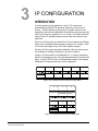
IP CONFIGURATION . . . . . . . . . . . . . . . . . . . . . . . 3-1
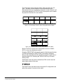
Introduction . . . . . . . . . . . . . . . . . . . . . . . . . . . . . . . . . . . . . . . . . . . . 3-1
IP Menus. . . . . . . . . . . . . . . . . . . . . . . . . . . . . . . . . . . . . . . . . . . . . . 3-2
IP Setup . . . . . . . . . . . . . . . . . . . . . . . . . . . . . . . . . . . . . . . . . . . . 3-3
Net Setup . . . . . . . . . . . . . . . . . . . . . . . . . . . . . . . . . . . . . . . . . . . 3-4
Connect. . . . . . . . . . . . . . . . . . . . . . . . . . . . . . . . . . . . . . . . . . . . . 3-5
User ID . . . . . . . . . . . . . . . . . . . . . . . . . . . . . . . . . . . . . . . . . . . . . 3-9
Password . . . . . . . . . . . . . . . . . . . . . . . . . . . . . . . . . . . . . . . . . . 3-10
Matrix IP Address . . . . . . . . . . . . . . . . . . . . . . . . . . . . . . . . . . . . 3-11
Control Delay . . . . . . . . . . . . . . . . . . . . . . . . . . . . . . . . . . . . . . . 3-11
Subnet Mask . . . . . . . . . . . . . . . . . . . . . . . . . . . . . . . . . . . . . . . . 3-13
Login Port . . . . . . . . . . . . . . . . . . . . . . . . . . . . . . . . . . . . . . . . . . 3-13
DHCP Control . . . . . . . . . . . . . . . . . . . . . . . . . . . . . . . . . . . . . . . 3-14
Clear Confirm Menu . . . . . . . . . . . . . . . . . . . . . . . . . . . . . . . . . . 3-15
Panel IP Address . . . . . . . . . . . . . . . . . . . . . . . . . . . . . . . . . . . . 3-16
IP Address Assignment . . . . . . . . . . . . . . . . . . . . . . . . . . . . . . 3-16
IP Gateway . . . . . . . . . . . . . . . . . . . . . . . . . . . . . . . . . . . . . . . . . 3-17
DNS Address . . . . . . . . . . . . . . . . . . . . . . . . . . . . . . . . . . . . . . . 3-18
Connection Type . . . . . . . . . . . . . . . . . . . . . . . . . . . . . . . . . . . . . 3-19
INSTALLATION . . . . . . . . . . . . . . . . . . . . . . . . . . . . 4-1
Introduction . . . . . . . . . . . . . . . . . . . . . . . . . . . . . . . . . . . . . . . . . . . . 4-1
Mounting Panels . . . . . . . . . . . . . . . . . . . . . . . . . . . . . . . . . . . . . . . . 4-1
Rack Mount Panels . . . . . . . . . . . . . . . . . . . . . . . . . . . . . . . . . . . . 4-1
Desktop Panels . . . . . . . . . . . . . . . . . . . . . . . . . . . . . . . . . . . . . . . 4-1
Wiring . . . . . . . . . . . . . . . . . . . . . . . . . . . . . . . . . . . . . . . . . . . . . . . . 4-4
Mains Power Cord . . . . . . . . . . . . . . . . . . . . . . . . . . . . . . . . . . . . . . 4-8
Power Connector Wiring . . . . . . . . . . . . . . . . . . . . . . . . . . . . . . . . 4-9
Analog Matrix Frame to Panel Wiring . . . . . . . . . . . . . . . . . . . . . . 4-9
Matrix Panel GPIO Connector Wiring . . . . . . . . . . . . . . . . . . . . . 4-10
Programmable Relay Contacts . . . . . . . . . . . . . . . . . . . . . . . . 4-11
Opto-Isolated Inputs . . . . . . . . . . . . . . . . . . . . . . . . . . . . . . . . 4-12
Auxiliary Audio Connector . . . . . . . . . . . . . . . . . . . . . . . . . . . . . . 4-13
AES-3 Option to AES-6 Interface . . . . . . . . . . . . . . . . . . . . . . . . 4-14
T-Adapter Option to DIG-2/DIF-102 Interface . . . . . . . . . . . . . . . 4-16
LAN Connector . . . . . . . . . . . . . . . . . . . . . . . . . . . . . . . . . . . . . . 4-17
Expansion Panel Output . . . . . . . . . . . . . . . . . . . . . . . . . . . . . . . 4-18
iv
Clear-Com
V-Series Panels User Guide
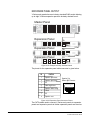
Front Panel Connectors . . . . . . . . . . . . . . . . . . . . . . . . . . . . . . . . . 4-19
Microphone Connector . . . . . . . . . . . . . . . . . . . . . . . . . . . . . . . . 4-19
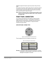
Headset Connectors . . . . . . . . . . . . . . . . . . . . . . . . . . . . . . . . . . 4-20
Mains AC Power . . . . . . . . . . . . . . . . . . . . . . . . . . . . . . . . . . . . . . . 4-22
Adjustments . . . . . . . . . . . . . . . . . . . . . . . . . . . . . . . . . . . . . . . . . . 4-22
Headset Sidetone . . . . . . . . . . . . . . . . . . . . . . . . . . . . . . . . . . . . 4-22
Headset Auto Detect . . . . . . . . . . . . . . . . . . . . . . . . . . . . . . . . . . 4-23
Panel Microphone Gain. . . . . . . . . . . . . . . . . . . . . . . . . . . . . . . . 4-24
Speaker Dim . . . . . . . . . . . . . . . . . . . . . . . . . . . . . . . . . . . . . . . . 4-24
Page Volume Level . . . . . . . . . . . . . . . . . . . . . . . . . . . . . . . . . . . 4-25
Panel-to-Matrix Card Baud Rate . . . . . . . . . . . . . . . . . . . . . . . . . 4-25
Configuration . . . . . . . . . . . . . . . . . . . . . . . . . . . . . . . . . . . . . . . . . 4-25
Expansion Panels . . . . . . . . . . . . . . . . . . . . . . . . . . . . . . . . . . . . . . 4-25
V Series Expansion Panels . . . . . . . . . . . . . . . . . . . . . . . . . . . . . 4-26
Mounting . . . . . . . . . . . . . . . . . . . . . . . . . . . . . . . . . . . . . . . . . . . 4-26
Power . . . . . . . . . . . . . . . . . . . . . . . . . . . . . . . . . . . . . . . . . . . . . 4-26
Panel Connection . . . . . . . . . . . . . . . . . . . . . . . . . . . . . . . . . . . . 4-26
Panel Configuration. . . . . . . . . . . . . . . . . . . . . . . . . . . . . . . . . . . 4-27
V-SERIES LOCAL MAINTENANCE MENU. . . . . . . 5-1
Menu Access. . . . . . . . . . . . . . . . . . . . . . . . . . . . . . . . . . . . . . . . . 5-1
Menu Navigation . . . . . . . . . . . . . . . . . . . . . . . . . . . . . . . . . . . . . . 5-2
Use of displays . . . . . . . . . . . . . . . . . . . . . . . . . . . . . . . . . . . . . . . 5-2
Commands available. . . . . . . . . . . . . . . . . . . . . . . . . . . . . . . . . . . 5-3
version . . . . . . . . . . . . . . . . . . . . . . . . . . . . . . . . . . . . . . . . . . . . 5-3
xpoint . . . . . . . . . . . . . . . . . . . . . . . . . . . . . . . . . . . . . . . . . . . . . 5-5
level . . . . . . . . . . . . . . . . . . . . . . . . . . . . . . . . . . . . . . . . . . . . . . 5-7
control . . . . . . . . . . . . . . . . . . . . . . . . . . . . . . . . . . . . . . . . . . . . 5-8
limit . . . . . . . . . . . . . . . . . . . . . . . . . . . . . . . . . . . . . . . . . . . . . 5-10
filter . . . . . . . . . . . . . . . . . . . . . . . . . . . . . . . . . . . . . . . . . . . . . 5-11
la . . . . . . . . . . . . . . . . . . . . . . . . . . . . . . . . . . . . . . . . . . . . . . . 5-12
mixer . . . . . . . . . . . . . . . . . . . . . . . . . . . . . . . . . . . . . . . . . . . . 5-13
setup . . . . . . . . . . . . . . . . . . . . . . . . . . . . . . . . . . . . . . . . . . . . 5-14
voicerec . . . . . . . . . . . . . . . . . . . . . . . . . . . . . . . . . . . . . . . . . . 5-15
voiceplay . . . . . . . . . . . . . . . . . . . . . . . . . . . . . . . . . . . . . . . . . 5-16
intrim . . . . . . . . . . . . . . . . . . . . . . . . . . . . . . . . . . . . . . . . . . . . 5-17
outtrim . . . . . . . . . . . . . . . . . . . . . . . . . . . . . . . . . . . . . . . . . . . 5-18
gpio . . . . . . . . . . . . . . . . . . . . . . . . . . . . . . . . . . . . . . . . . . . . . 5-19
module . . . . . . . . . . . . . . . . . . . . . . . . . . . . . . . . . . . . . . . . . . . 5-20
Clear-Com
V-Series Panels User Guide
v
SPECIFICATIONS . . . . . . . . . . . . . . . . . . . . . . . . . . 6-1
GLOSSARY . . . . . . . . . . . . . . . . . . . . . . . . . . . . . . . 7-1
Eclipse Manuals . . . . . . . . . . . . . . . . . . . . . . . . . . . . . . . . . . . . . . . . 7-5
Software Manuals . . . . . . . . . . . . . . . . . . . . . . . . . . . . . . . . . . . . . 7-5
Hardware Manuals . . . . . . . . . . . . . . . . . . . . . . . . . . . . . . . . . . . . 7-5
LIMITED WARRANTY . . . . . . . . . . . . . . . . . . . . . . . W-I
TECHNICAL SUPPORT & REPAIR POLICY. . . . . W-V
TECHNICAL SUPPORT POLICY . . . . . . . . . . . . . . . . . . . . . . . . . . W-v
RETURN MATERIAL AUTHORIZATION POLICY . . . . . . . . . . . . . W-vi
REPAIR POLICY . . . . . . . . . . . . . . . . . . . . . . . . . . . . . . . . . . . . . W-viii
vi
Clear-Com
V-Series Panels User Guide
FIGURES
Figure 1-1 V12LD Front Panel Controls and Indicators................... 1-3
Figure 1-2 V12PD Front Panel Controls and Indicators .................. 1-3
Figure 1-3 V12RD Front Panel Controls and Indicators .................. 1-3
Figure 1-4 V24LD Front Panel Controls and Indicators................... 1-4
Figure 1-5 V24PD Front Panel Controls and Indicators .................. 1-4
Figure 1-6 V24RD Front Panel Controls and Indicators .................. 1-4
Figure 1-7 V12LDE Expansion Front Panel Controls and Indicators.....
1-5
Figure 1-8 V12PDE Expansion Front Panel Controls and Indicators ....
1-5
Figure 1-9 V12RDE Expansion Front Panel Controls and Indicators ....
1-5
Figure 1-10 V12LDD Front Panel Controls and Indicators .............. 1-6
Figure 1-11 V12PDD Front Panel Controls and Indicators.............. 1-6
Figure 1-12 V12RDD Front Panel Controls and Indicators.............. 1-7
Figure 1-13 Line Key Display Window Areas .................................. 1-8
Figure 1-14 Lever Key Panel Volume Buttons................................. 1-8
Figure 1-15 Pushbutton Panel Volume Buttons............................... 1-9
Figure 1-16 Rotary Panel Volume Buttons ...................................... 1-9
Figure 1-17 Key Status Icons ........................................................ 1-10
Figure 1-18 Reply Key Display Window Areas .............................. 1-10
Figure 1-19 IFB Talk Level Adjust ................................................. 1-19
Figure 1-20 V-Series Audio Block Diagram ................................... 1-20
Figure 2-1 Fast Key Assign for Rack Mount Panels ........................ 2-2
Figure 2-2 Fast Key Assign for Desktop Panels .............................. 2-2
Figure 2-3 Basic Steps to Fast Assign a Key .................................. 2-4
Figure 2-4 Main Menu Display for Rack Mount Panels ................... 2-5
Figure 2-5 Main Menu Display for Desktop Panels ......................... 2-5
Figure 2-6 System Information Display for Rack Mount Panels ...... 2-6
Figure 2-7 System Information Display for Desktop Panels ............ 2-6
Figure 2-8 View Keys Display for Rack Mount Panels .................... 2-7
Figure 2-9 View Keys Display for Desktop Panels .......................... 2-7
Figure 2-10 Key Info Display for Rack Mount Panels ...................... 2-8
Figure 2-11 Key Info Display for Desktop Panels ............................ 2-8
Figure 2-12 Party Line Menu for Rack Mount Panels...................... 2-9
Figure 2-13 Party Line Menu for Desktop Panels............................ 2-9
Figure 2-14 Party Line Labels for Rack Mount Panels .................... 2-9
Figure 2-15 Party Line Labels for Desktop Panels ........................ 2-10
Figure 2-16 Fixed Group List for Rack Mount Panels.................... 2-10
Figure 2-17 Fixed Group Menu for Desktop Panels ...................... 2-11
Figure 2-18 Fixed Group Labels for Rack Mount Panels............... 2-11
Figure 2-19 Fixed Group Labels for Desktop Panels..................... 2-11
Figure 2-20 Nearby Panels Display for Rack Mount Panels.......... 2-12
Figure 2-21 Nearby Panels Display for Desktop Panels................ 2-12
Figure 2-22 Monitor Menu for Rack Mount Panels ........................ 2-13
Figure 2-23 Monitor Menu for Desktop Panels .............................. 2-13
Clear-Com
V-Series Panels User Guide
i
Figure 2-24 Forced Listen Source Interfaces for Rack Mount Panels ...
2-13
Figure 2-25 Forced Listen Source Interfaces for Desktop Panels . 2-14
Figure 2-26 Forced Listen Destinations for Rack Mount Panels ... 2-14
Figure 2-27 Forced Listen Destinations for Desktop Panels ......... 2-14
Figure 2-28 Local Preferences PIN Code Request ....................... 2-15
Figure 2-29 Local Preferences PIN Code Request ....................... 2-15
Figure 2-30 Lever and Pushbutton PIN Code Input....................... 2-16
Figure 2-31 Rotary Control PIN Code Input................................... 2-16
Figure 2-32 Local Preferences Display for Rack Mount Panels .... 2-16
Figure 2-33 Local Preferences Display for Desktop Panels .......... 2-17
Figure 2-34 Timeout Display for Rack Mount Panels .................... 2-18
Figure 2-35 Timeout Display for Desktop Panels .......................... 2-18
Figure 2-36 Level Adjust Display for Rack Mount Panels.............. 2-19
Figure 2-37 Level Adjust Display for Rack Desktop Panels .......... 2-19
Figure 2-38 Brightness Adjustment Display for Rack Mount Panels .....
2-21
Figure 2-39 Brightness Adjustment Display for Desktop Panels ... 2-21
Figure 2-40 Messages for Rack Mount Panels.............................. 2-22
Figure 2-41 Messages for Desktop Panels.................................... 2-22
Figure 2-42 Reset Crosspoints Display for Rack Mount Panels.... 2-23
Figure 2-43 Reset Crosspoints Display for Desktop Panels.......... 2-23
Figure 2-44 System Configuration PIN Code Request .................. 2-24
Figure 2-45 System Configuration PIN Code Request .................. 2-24
Figure 2-46 System Configuration Menu for Rack Mount Panels.. 2-24
Figure 2-47 System Configuration Menu for Desktop Panels........ 2-25
Figure 2-48 Party Line Menu for Rack Mount Panels.................... 2-26
Figure 2-49 Party Line Menu for Desktop Panels.......................... 2-26
Figure 2-50 Party Line Membership for Rack Mount Panels ......... 2-26
Figure 2-51 Party Line Membership for Desktop Panels ............... 2-27
Figure 2-52 Party Line Labels for Rack Mount Panels .................. 2-27
Figure 2-53 Party Line Labels for Desktop Panels ........................ 2-27
Figure 2-54 Party Line Labels for Rack Mount Panels .................. 2-28
Figure 2-55 Party Line Labels for Desktop Panels ........................ 2-28
Figure 2-56 Fixed Group Menu for Rack Mount Panels ................ 2-29
Figure 2-57 Fixed Group Menu for Desktop Panels ...................... 2-29
Figure 2-58 Fixed Group Membership for Rack Mount Panels ..... 2-30
Figure 2-59 Fixed Group Membership for Desktop Panels ........... 2-30
Figure 2-60 Fixed Group Labels for Rack Mount Panels............... 2-30
Figure 2-61 Fixed Group Labels for Desktop Panels..................... 2-31
Figure 2-62 Fixed Group Labels for Rack Mount Panels............... 2-31
Figure 2-63 Fixed Group Labels for Desktop Panels..................... 2-32
Figure 2-64 Local Panel Menu for Rack Mount Panels ................. 2-32
Figure 2-65 Local Panel Menu for Desktop Panels ....................... 2-33
Figure 2-66 Panel Attributes Menu for Rack Mount Panels........... 2-33
Figure 2-67 Panel Attributes Menu for Desktop Panels................. 2-34
Figure 2-68 Local Key Assign Menu for Rack Mount Panels ........ 2-35
Figure 2-69 Local Key Assign Menu for Desktop Panels .............. 2-35
Figure 2-70 Key Assign Menu for Rack Mount Panels .................. 2-36
Figure 2-71 Key Assign Menu for Rack Mount Panels .................. 2-36
ii
Clear-Com
V-Series Panels User Guide
Figure 2-72 Get Label menu for Rack Mount Panels .................... 2-37
Figure 2-73 Get Label menu for Desktop Panels .......................... 2-37
Figure 2-74 Sort Group Menu for Rack Mount Panels .................. 2-37
Figure 2-75 Sort Group Menu for Desktop Panels ........................ 2-38
Figure 2-76 Remote Panel menu for Rack Mount Panels ............. 2-39
Figure 2-77 Remote Panels menu for Desktop Panels ................. 2-39
Figure 2-78 Sort Group Menu for Rack Mount Panels .................. 2-40
Figure 2-79 Sort Group Menu for Desktop Panels ........................ 2-40
Figure 2-80 Remote Panel Menu for Rack Mount Panels ............. 2-41
Figure 2-81 Remote Panel Menu for Desktop Panels ................... 2-41
Figure 2-82 Panel Attributes Menu for Rack Mount Panels........... 2-42
Figure 2-83 Panel Attributes Menu for Desktop Panels................. 2-42
Figure 2-84 Forced Listen Configuration Menu for Rack Mount Panels
2-43
Figure 2-85 Forced Listen Configuration Menu for Desktop Panels......
2-43
Figure 2-86 Forced Listen Sources Menu for Rack Mount Panels 2-44
Figure 2-87 Forced Listen Sources Menu for Desktop Panels ...... 2-44
Figure 2-88 Forced Listen Source Interfaces for Rack Mount Panels ...
2-44
Figure 2-89 Forced Listen Source Interfaces for Desktop Panels . 2-45
Figure 2-90 Forced Listen Source Panels for Rack Mount Panels 2-45
Figure 2-91 Forced Listen Source Panels for Desktop Panels...... 2-45
Figure 2-92 Forced Listen Destinations Menu for Rack Mount Panels .
2-46
Figure 2-93 Forced Listen Destinations Menu for Desktop Panels 2-46
Figure 2-94 Forced Listen Destination Interfaces for Rack Mount Panels .................................................................................................. 2-46
Figure 2-95 Forced Listen Destination Interfaces for Desktop Panels ..
2-47
Figure 2-96 Forced Listen Source Panels for Rack Mount Panels 2-47
Figure 2-97 Forced Listen Source Panels for Desktop Panels...... 2-47
Figure 2-98 Input Levels Menu for Rack Mount Panels................. 2-48
Figure 2-99 Input Levels Menu for Desktop Panels....................... 2-48
Figure 2-100 Sort Group Members Menu for Rack Mount Panels 2-49
Figure 2-101 Sort Group Members Menu for Desktop Panels ...... 2-49
Figure 2-102 Input Level Set Menu for Rack Mount Panels .......... 2-50
Figure 2-103 Input Level Set Menu for Desktop Panels ................ 2-50
Figure 2-104 Output Level Configuration Menu for Rack Mount Panels
2-50
Figure 2-105 Output Level Configuration Menu for Desktop Panels .....
2-51
Figure 2-106 Sort Group Output Levels Menu for Rack Mount Panels .
2-51
Figure 2-107 Sort Group Output Levels Menu for Desktop Panels 2-51
Figure 2-108 Output Level Set Menu for Rack Mount Panels ....... 2-52
Figure 2-109 Output Level Set Menu for Desktop Panels ............. 2-52
Figure 2-110 Diagnostic Menu for Rack Mount Panels ................. 2-53
Figure 2-111 Diagnostic Menu for Desktop Panels ....................... 2-53
Figure 2-112 Offline Panel Display for Rack Mount Panels........... 2-54
Clear-Com
V-Series Panels User Guide
iii
Figure 2-113 Offline Panel Display for Desktop Panels................. 2-55
Figure 2-114 System Data Menu for Rack Mount Panels ............. 2-55
Figure 2-115 System Data Menu for Desktop Panels ................... 2-56
Figure 2-116 Upgrade Menu for Rack Mount Panels .................... 2-56
Figure 2-117 Upgrade Menu for Desktop Panels .......................... 2-57
Figure 2-118 Upgrade Confirmation Menu for Rack Mount Panels 2-57
Figure 2-119 Upgrade Conformation for Desktop Panels.............. 2-57
Figure 2-120 Upgrade Progress Menu for Rack Mount Panels..... 2-58
Figure 2-121 Upgrade Progress for Desktop Panels..................... 2-58
Figure 2-122 Call Menu for Rack Mount Panels............................ 2-58
Figure 2-123 Call Menu for Desktop Panels.................................. 2-59
Figure 2-124 Call Sort Menu for Rack Mount Panels .................... 2-59
Figure 2-125 Call Sort Menu for Desktop Panels .......................... 2-59
Figure 2-126 Dial Menu for Rack Mount Panels............................ 2-60
Figure 2-127 Dial Menu for Desktop Panels.................................. 2-61
Figure 2-128 Rackmount Panel Dial Menu from Keypad Shortcut 2-61
Figure 2-129 Desktop Panel Dial menu from Keypad Shortcut ..... 2-62
Figure 2-130 Local Exclusive for Rack Mount Panels ................... 2-62
Figure 2-131 Local Exclusive for Desktop Panels ......................... 2-63
Figure 2-132 Local Page Override for Rack Mount Panels ........... 2-63
Figure 2-133 Local Page Override for Desktop Panels ................. 2-64
Figure 2-134 Assignment Menu for Rack Mount Panels ............... 2-64
Figure 2-135 Assignment Menu for Desktop Panels ..................... 2-65
Figure 2-136 Rotary Panel IFB Level Setup .................................. 2-66
Figure 2-137 Setting IFB Destination Level ................................... 2-66
Figure 2-138 Setting IFB Source Level.......................................... 2-67
Figure 2-139 Supervise Menu for Rack Mount Panels .................. 2-69
Figure 2-140 Supervise Menu for Desktop Panels ........................ 2-69
Figure 2-141 Supervise Label Menu for Rack Mount Panels ........ 2-69
Figure 2-142 Supervise Label Menu for Desktop Panels .............. 2-70
Figure 2-143 Supervisor Error Message for Rack Mount Panels .. 2-70
Figure 2-144 Supervisor Error Message for Desktop Panels ........ 2-71
Figure 2-145 Shift Page Menu for Rack Mount Panels ................. 2-72
Figure 2-146 Shift Page Menu for Desktop Panels ....................... 2-73
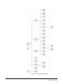
Figure 2-147 V-Series Menu Structure .......................................... 2-74
Figure 2-148 Lever Key Panel Volume Buttons............................. 2-77
Figure 2-149 Pushbutton Panel Volume Buttons........................... 2-78
Figure 2-150 Rotary Panel Volume Buttons .................................. 2-78
Figure 3-1 Rack Mount Panel Passcode Entry Menu...................... 3-1
Figure 3-2 Desktop Panel Passcode Entry Menu............................ 3-1
Figure 3-3 Rack Mount Panel IP Setup Using Maintenance Mode . 3-2
Figure 3-4 Desktop Panel IP Setup Using Maintenance Mode ....... 3-2
Figure 3-5 Rack Mount Panel IP Setup Menu ................................. 3-3
Figure 3-6 Desktop Panel IP Setup Menu ....................................... 3-3
Figure 3-7 Rack Mount Panel IP Setup Menu ................................. 3-4
Figure 3-8 Desktop Panel IP Setup Menu ....................................... 3-4
Figure 3-9 Rack Mount Panel IP Connection .................................. 3-5
Figure 3-10 Desktop Panel IP Connecting ...................................... 3-5
Figure 3-11 Rack Mount Panel User ID Input Menu........................ 3-9
Figure 3-12 Desktop Panel User ID Input Menu.............................. 3-9
iv
Clear-Com
V-Series Panels User Guide
Figure 3-13 Rack Mount Panel Password Input Menu .................. 3-10
Figure 3-14 Desktop Panel Password Input Menu ........................ 3-10
Figure 3-15 Rack Mount Panel Matrix IP Address Input................ 3-11
Figure 3-16 Desktop Panel Matrix IP Address Input...................... 3-11
Figure 3-17 Rack Mount Panel Control Delay Input ...................... 3-12
Figure 3-18 Desktop Panel Matrix Control Delay Input ................. 3-12
Figure 3-19 Rack Mount Panel Subnet Mask ............................... 3-13
Figure 3-20 Desktop Panel Subnet Mask ..................................... 3-13
Figure 3-21 Rack Mount Panel Login Port Input............................ 3-13
Figure 3-22 Desktop Panel Login Port Input.................................. 3-14
Figure 3-23 Rack Mount Panel DHCP Control .............................. 3-14
Figure 3-24 Desktop Panel DHCP Control .................................... 3-15
Figure 3-25 Rack Mount Panel Confirm Menu .............................. 3-15
Figure 3-26 Desktop Panel Confirm Menu .................................... 3-15
Figure 3-27 Rack Mount Panel IP Address Menu ......................... 3-16
Figure 3-28 Desktop Panel IP Address Menu ............................... 3-16
Figure 3-29 Rack Mount Panel Gateway IP Address Menu .......... 3-17
Figure 3-30 Desktop Panel Gateway IP Address Menu ................ 3-17
Figure 3-31 Rack Mount Panel DNS Server IP Address Menu ..... 3-18
Figure 3-32 Desktop Panel DNS Server IP Address Menu ........... 3-18
Figure 3-33 Rack Mount Panel IP Connection Type Menu ........... 3-19
Figure 3-34 Desktop Panel IP Connection Type Menu ................. 3-19
Figure 3-35 IP Menu Structure ...................................................... 3-20
Figure 4-1 Desktop Wall Mount Kit .................................................. 4-2
Figure 4-2 Desktop Panel Retaining Screws ................................... 4-2
Figure 4-3 Desktop Panel with Refitted Display .............................. 4-3
Figure 4-4 Desktop Casing Without Lower Bracket......................... 4-3
Figure 4-5 Desktop with Lower Bracket Fitted................................. 4-4
Figure 4-6 V Series Main Panel Rear Connectors (no AES-3 or
T-Adapter)........................................................................................ 4-5
Figure 4-7 V Series Main Panel Rear Connectors (AES-3)............. 4-5
Figure 4-8 V-Series Main Panel Rear Connectors (T-Adapter) ....... 4-6
Figure 4-9 V Series Expansion Panel Rear Connectors.................. 4-6
Figure 4-10 V-Series Desktop Panel Rear Connectors (no AES-3 or
T-Adapter)........................................................................................ 4-6
Figure 4-11 V Series Desktop Panel Rear Connectors (AES-3) ..... 4-7
Figure 4-12 V Series Desktop Panel Rear Connectors (T-Adapter) 4-7
Figure 4-13 Power Supply Socket ................................................... 4-9
Figure 4-14 Matrix Frame to Panel Wiring..................................... 4-10
Figure 4-15 GPIO Connector Pinout.............................................. 4-10
Figure 4-16 Example of Wiring to Use a Logic Input ..................... 4-12
Figure 4-17 Auxiliary Audio Connector .......................................... 4-13
Figure 4-18 V-Series Panel with AES-3 Interface.......................... 4-14
Figure 4-19 V-Series Panel Connected by 3rd Party Network ...... 4-15
Figure 4-20 V-Series Panel with T-Adapter Interface .................... 4-16
Figure 4-21 LAN Connector Pinout................................................ 4-17
Figure 4-22 Example of Daisy Chained Panels ............................. 4-18
Figure 4-23 Expansion Panel Connector Pinout............................ 4-18
Figure 4-24 Microphone Connector Pinout.................................... 4-19
Figure 4-25 XLR-4M Headset Connector ...................................... 4-20
Clear-Com
V-Series Panels User Guide
v
Figure 4-26 XLR-5F Headset Connector ....................................... 4-20
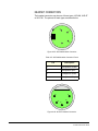
Figure 4-27 XLR-7M Headset Connector ...................................... 4-21
Figure 4-28 Headset Detect Switch Location ................................ 4-23
Figure 4-29 Headset Detect DIP Switch Settings .......................... 4-24
Figure 5-1 Rack Mount Panel IP Setup Using Maintenance Mode . 5-1
Figure 5-2 Desktop Panel IP Setup Using Maintenance Mode ....... 5-1
Figure 5-3 Position of Maintenance Menu on Panels ...................... 5-2
Figure 5-4 Layout of Maintenance Menu ......................................... 5-3
Figure 5-5 Version Display .............................................................. 5-3
Figure 5-6 Crosspoint Setting Display ............................................. 5-5
Figure 5-7 Level Setting Display...................................................... 5-7
Figure 5-8 Control Setting Display................................................... 5-8
Figure 5-9 Limit Settings Display ................................................... 5-10
Figure 5-10 Filter Settings Display................................................. 5-11
Figure 5-11 Listen Again Settings Display..................................... 5-12
Figure 5-12 Mixer Settings Display................................................ 5-13
Figure 5-13 Setup Display Settings ............................................... 5-14
Figure 5-14 Voice Recorder Control Display ................................. 5-15
Figure 5-15 Voice Play Settings .................................................... 5-16
Figure 5-16 Input Trim Settings Display ........................................ 5-17
Figure 5-17 Output Trim Settings Display...................................... 5-18
Figure 5-18 GPIO Display Settings................................................ 5-19
Figure 5-19 Display for Module Settings........................................ 5-20
vi
Clear-Com
V-Series Panels User Guide
1
INTRODUCTION
This chapter describes how to operate the V-Series panels. Panel
operators can use this manual after the Eclipse System has been
correctly installed and configured.
DESCRIPTION
V-SERIES PANELS
The V series family of panels consists of twelve lever key, push-button
and rotary control panels as described below.
Lever Key Panels
• V12LD - 19” rack mount 1RU 12 lever key display panel.
• V24LD - 19” rack mount 2RU 24 lever key display panel with dial
pad.
• V12LDE - 19” rack mount 1RU 12 lever key display expansion
panel.
• V12LDD - desktop 12 lever key display panel.
Pushbutton Panels
• V12PD - 19” rack mount 1RU 12 pushbutton display panel.
• V24PD - 19” rack mount 2RU 24 pushbutton display panel with
dial pad.
• V12PDE - 19” rack mount 1RU 12 pushbutton display expansion
panel.
• V12PDD - desktop 12 pushbutton display panel.
Rotary Control Panels
• V12RD - 19” rack mount 1RU 12 rotary control display panel.
• V24RD - 19” rack mount 2RU 24 rotary control display panel with
dial pad.
• V12RDE - 19” rack mount 1RU 12 rotary control display
expansion panel.
• V12RDD - desktop 12 rotary control display panel
Clear-Com
V-Series Panels User Guide
1-1
V-SERIES PANEL OPTIONS
The V series panels can be equipped with the following headset
connector options (one connector only):
• XLR-4M locking headset connection.
• XLR-5F headset connection.
• XLR-7M headset connection.
The V12LD and V24LD panels can support the following expansion
panels:
• Up to eight V12LDE expansion panels in a daisy chain.
The V12PD and V24PD panels can support the following expansion
panels:
• Up to eight V12PDE expansion panels in a daisy chain.
The V12RD and V24RD panels can support the following expansion
panels:
• Up to eight V12RDE expansion panels in a daisy chain.
The V12LDD, V12PDD and V12RDD desktop panels do not support
expansion panels.
Expansion panel types (lever key, pushbutton or rotary control) may
not be mixed in a daisy chain of such panels and must be connected to
a main panel of the same type.
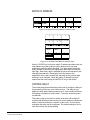
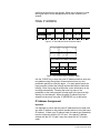
FRONT-PANEL CONTROLS AND INDICATORS
This section describes the front-panel controls and indicators. These
include:
• The displays for each key
• Intercom and program controls
• Talk/listen selectors and indicators
• “Answer Back” facility
• Keypad buttons (V24LD, V24PD, V24RD, V12LDD, V12PDD and
V12RDD panels only)
• Microphone and headset connectors
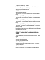
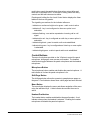
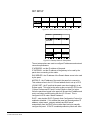
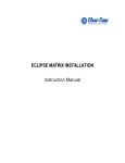
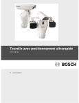
Figure 1-1 illustrates the V12LD front panel controls and indicators
1-2
Clear-Com
V-Series Panels User Guide
.
Microphone
Socket
MIC
On
Shift
MIC
Page Shift
Indicator Select Page
LED
LED
Select
Key
Talk/
Listen Display
L/S Cut
LED
Loudspeaker
Reset Menu Menu Reply Volume Volume Talk/Listen Main
Headset H/S H/S
Socket LED Select
Select Select Key Down Up
Status LED Volume
Control
LED
and
Switch
Main
Volume
Indicator
LED
Info
LED
Auxiliary
Volume
Indicator
LED
Auxiliary
Volume
Control
and
Switch
Figure 1-1: V12LD Front Panel Controls and Indicators
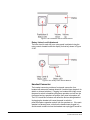
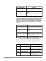
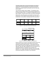
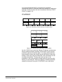
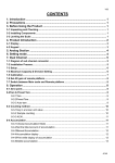
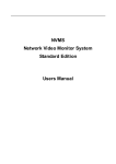
Figure 1-2 illustrates the V12PD front panel controls and indicators.
Shift
Page Shift
MIC
Microphone MIC Indicator Select Page
On LED
LED
Select
Socket
Talk/
Listen
& Status
Key
Display
Volume
Down
Headset H/S H/S Reset Menu Menu Reply
Select Select Key
Socket LED Select
LED
Volume
Up
L/S Cut
Info
LED
Loudspeaker LED
Main
Volume
Control
and
Switch
Main
Auxiliary
Volume Volume
Indicator Indicator
LED
LED
Auxiliary
Volume
Control
and
Switch
Figure 1-2: V12PD Front Panel Controls and Indicators
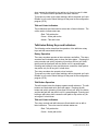
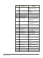
Figure 1-3 illustrates the V12RD front panel controls and indicators.
Shift
Page Shift
MIC
Microphone MIC Indicator Select Page
On
LED
Select
LED
Socket
Listen
& Level
Headset H/S H/S Reset Menu Menu Reply
Select Select Key
Socket LED Select
LED
Key
Display
Talk Button
L/S Cut
Info
LED
Loudspeaker LED
Main
Volume
Control
and
Switch
Main
Auxiliary
Volume Volume
Indicator Indicator
LED
LED
Auxiliary
Volume
Control
and
Switch
Figure 1-3: V12RD Front Panel Controls and Indicators
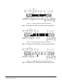
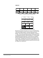
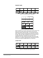
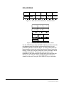
Figure 1-4 illustrates the V24LD front panel controls and indicators.
Clear-Com
V-Series Panels User Guide
1-3
Shift
Page
MIC
MIC Indicator Select
Headset MIC
LED
Socket Socket On LED
H/S
LED
1
2
3
#
4
5
6
0
7
8
9
*
H/S
Keypad Reset
Select
Shift
Page
Select
Talk/Listen
Key
Menu Menu Reply
Select Select Key
LED
L/S Cut
LED
Loudspeaker
Key
Display
Volume
Down
Volume
Up
Talk/Listen
Status LED
Main
Volume
Control
and
Switch
Main
Volume
Indicator
LED
Auxiliary
Volume
Indicator
LED
Info
LED
Auxiliary
Volume
Control
and
Switch
Figure 1-4: V24LD Front Panel Controls and Indicators
Figure 1-5 illustrates the V24PD front panel controls and indicators
MIC
Headset MIC
Socket Socket On
H/S
LED
Shift
MIC
Page Shift
Indicator Select Page
LED
LED
Select
1
2
3
#
4
5
6
0
7
8
9
*
H/S
Keypad Reset Menu
Select
Select
Talk/
Listen
& Status
Menu Reply
Select Key
LED
Key
Display
Volume
Down
Volume
Up
L/S Cut
LED
Main
Volume
Control
and
Switch
Loudspeaker
Main
Volume
Indicator
LED
Auxiliary
Volume
Indicator
LED
Info
LED
Auxiliary
Volume
Control
and
Switch
Figure 1-5: V24PD Front Panel Controls and Indicators
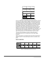
Figure 1-6 illustrates the V24RD front panel controls and indicators
MIC
Headset MIC
Socket Socket On
H/S
LED
Shift
MIC
Page Shift
Indicator Select Page
LED
LED
Select
1
2
3
#
4
5
6
0
7
8
9
*
H/S
Keypad Reset Menu
Select
Select
Listen
& Level
Menu Reply
Select Key
LED
Key
Display
Talk Button
L/S Cut
LED
Main
Volume
Control
and
Switch
Loudspeaker
Main
Volume
Indicator
LED
Auxiliary
Volume
Indicator
LED
Info
LED
Auxiliary
Volume
Control
and
Switch
Figure 1-6: V24RD Front Panel Controls and Indicators
Figure 1-7 illustrates the V12LDE expansion front panel controls and
indicators.
1-4
Clear-Com
V-Series Panels User Guide
Talk/Listen
Key
Reply Key
Talk/Listen
Status LED
Key
Display
Volume
Down
Volume
Up
Figure 1-7: V12LDE Expansion Front Panel Controls and Indicators
Figure 1-8 illustrates the V12PDE expansion front panel controls and
indicators.
Talk/Listen
& Status
Pushbutton
Reply Key
Volume
Down
Key
Display
Volume
Up
Figure 1-8: V12PDE Expansion Front Panel Controls and Indicators
Figure 1-9 illustrates the V12RDE expansion front panel controls and
indicators.
Listen
& Level
Key
Display
Reply Key
Talk Button
Figure 1-9: V12RDE Expansion Front Panel Controls and Indicators
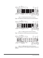
Figure 1-10 illustrates the V12LDD front panel controls and indicators.
Clear-Com
V-Series Panels User Guide
1-5
Talk/Listen Volume
Key
Down
Volum
Up
Key
Display
MIC
Socket
LS Cut
Loudspeaker
LED
Info
LED
Auxiliary
Volume
Indicator
LED
Auxiliary
Volume
Control
Shift Page
Select LED
Shift
Page Select
Reply Key
Talk/Listen
Status LED
1
2
3
#
4
5
6
0
7
8
9
*
Main
Headset Main
Keypad MIC
Socket Volume Volume
On
Control Indicator
LED
Menu
Select LED
Menu Select
H/S H/S
MIC
LED Select Indicator
LED
Figure 1-10: V12LDD Front Panel Controls and Indicators
Figure 1-11 illustrates the V12PDD front panel controls and indicators.
Talk/Listen Volume
& Status
Down
Volum
Up
Key
Display
MIC
Socket
LS Cut
Loudspeaker
LED
Info
LED
Auxiliary
Volume
Indicator
LED
Auxiliary
Volume
Control
Shift Page
Select LED
Shift
Page Select
Reply Key
Talk/Listen
Status LED
1
2
3
#
4
5
6
0
7
8
9
*
Main
Headset Main
Keypad MIC
Socket Volume Volume
On
Control Indicator
LED
Menu
Select LED
Menu Select
H/S H/S
MIC
LED Select Indicator
LED
Figure 1-11: V12PDD Front Panel Controls and Indicators
Figure 1-12 illustrates the V12RDD front panel controls and indicators.
1-6
Clear-Com
V-Series Panels User Guide
Listen
& Level
Talk Button
Key
Display
MIC
Socket
LS Cut
Loudspeaker
LED
Info
LED
Auxiliary
Volume
Indicator
LED
Auxiliary
Volume
Control
Shift Page
Select LED
Shift
Page Select
1
2
3
#
4
5
6
0
7
8
9
*
Main
Headset Main
Keypad MIC
Socket Volume Volume
On
Control Indicator
LED
Reply Key
Menu
Select LED
Menu Select
H/S H/S
MIC
LED Select Indicator
LED
Figure 1-12: V12RDD Front Panel Controls and Indicators
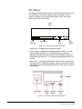
DISPLAY WINDOW
A display window is located next to each selector and shows the
currently assigned label for that selector. Assigned labels are
accessed when the selector is pushed (pushbutton and rotary panels)
or toggled (lever key panel). Each selector can be assigned as many
as nine labels via the main page and eight shift pages. Each label can
represent a talk or listen path to a panel, interface, fixed group, or party
line, or can activate a programmable control function.
The display window for each key can display up to ten Latin or
Katakana characters or five Kanji characters together with status
indicators for the key. These indicators are:
• Currently selected page
• Latched talk indicator
• Latched listen indicator
• Panel monitoring indicator
• Microphone indicator
• Incoming Vox indicator
• Antenna active indicator
• Destination type indicator e.g. Party Line, IFB, Fixed Group
• Remote panel connection
Clear-Com
V-Series Panels User Guide
1-7
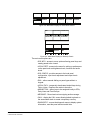
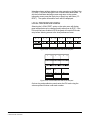
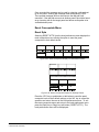
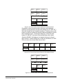
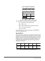
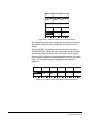
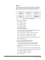
KEY DISPLAY
The display associated with each line key provides a text area for up to
ten characters to be used to display audio route labels or menu
options, selection arrows, audio level indicator, scroll arrows and
function/audio source indication.
Label
Field
Latch
Indicator
Audio Level
Key
Type
Key
Status
Figure 1-13: Line Key Display Window Areas
• Label Field - 10 character field for the key label.
• Latch Indicator - indicates the talk/listen status of the key. A down
arrow indicates that the key is a latched talk key, an up arrow
indicates a latched listen key and both arrows together indicate an
latched talk and listen key. If no arrows are displayed the key is not
latched.
• Audio Level - a bar graph indicating the audio level set on that route.
The audio level is controlled using the volume control buttons below
the display (lever key and pushbutton panels) or the rotary control on
rotary panels.
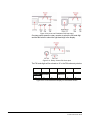
Figure 1-14: Lever Key Panel Volume Buttons
1-8
Clear-Com
V-Series Panels User Guide
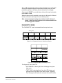
Figure 1-15: Pushbutton Panel Volume Buttons
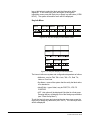
Figure 1-16: Rotary Panel Volume Buttons
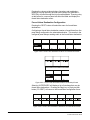
• Key Type - indicates the type of route or action the panel key is
connected to. These are:
• PL - Party Line
• IFB - Interruptible Foldback
• FG - Fixed Group (includes stacked keys)
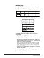
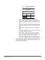
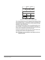
• Key Status - displays an icon indicating the status of this key. The
icons are shown in the figure below.
Clear-Com
V-Series Panels User Guide
1-9
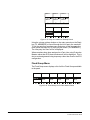
Incoming VOX
Antenna (2 Way Radio)
Telephone
Remote Panel Connected
Ctrl Relay
Speed Dial
Figure 1-17: Key Status Icons
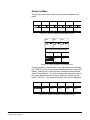
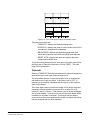
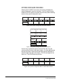
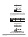
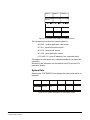
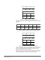
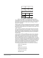
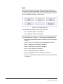
REPLY KEY DISPLAY
The display associated with the Reply key provides a text area for up
to ten characters to be used to display labels or menu options,
selection arrows, audio level indicator, scroll arrows and function/audio
source indication.
Label
Field
Shift Page
Latch
Indicator (only current page
displayed)
Key
Type
Panel
Monitoring
Figure 1-18: Reply Key Display Window Areas
• Label Field - 10 character field for the “Reply” label or the caller label.
• Latch Indicator - indicates the latch status of the key. As the Reply
key is non-latching these indicators will not be displayed.
• Shift Page - The number of the current shift page. Only the current
page number is displayed with the digit in the position shown in the
illustration.
1-10
Clear-Com
V-Series Panels User Guide
• Key Type - indicates the type of route or action the Reply key is
connected to. When replying to an incoming call from a Party Line,
Fixed Group or IFB the caller port is displayed rather than the Party
Line, Fixed Group or IFB, and the reply key only connects to the
caller.
• Panel Monitoring - displays an ear icon if the panel is being
monitored.
FONTS
The Eclipse V5 release has additional font support for the V-Series
panels. The details of the fonts supported and any limitations are
described below.
1. Basic Latin. The backslash is a Yen character. This is a
size-maximized font (no descenders, lower-case characters are not
relative in size to upper-case characters). This covers Unicode 32 to
127 (decimal), 0x20 to 0x7F (hex). The V-Series panel display will
support ten characters.
2. Cyrillic. This is a normal, relatively-sized font. The V-Series panel
display will support ten characters. Covers Unicode 1024 to 1279
(decimal), 0x400 to 0x4FF (hex) with some missing characters.
3. Hiragana. The V-Series panel display will support five characters.
This covers the codepoint range 12352 to 12447 (decimal), 0x3040
to 0x309F (hex).
4. Full-width Katakana. The V-Series panel display will support five
characters as this is a normal width font. This covers the codepoint
range 12448 to 12543 (decimal), 0x30A0 to 0x30FF (hex) with some
missing characters.
5. Kanji. There are about 17,000 out of the 21,000 characters. The
V-Series panel display will support five characters. This covers the
codepoint range 19968 to 40895 (decimal), 0x4E00 to 0x9FBF
(hex).
6. Hangul. The V-Series panel display will support five characters,
range is 44032 to 55215 (decimal), 0xAC00 to 0xD7AF (hex).
7. Half-width katakana. The V-Series panel will support ten characters.
The codepoint range is 65376 to 65440 (decimal), 0xFF60 to
0xFFA0 (hex).
PANEL OPERATION
The operation of V-Series panels is described in this section. Lever
key panels, pushbutton panels and rotary control panels have some
operational differences which will be described in this section.
MIC ON BUTTON
The Mic On/Off button turns the currently selected microphone
(gooseneck microphone or headset microphone) on or off. When the
microphone is on the red LED will come on to indicate that the
Clear-Com
V-Series Panels User Guide
1-11
microphone is active. If a panel key is used to establish a talk
connection the panel microphone will automatically be enabled and the
indicator will light. When the connection is terminated the microphone
will automatically be disabled.
SHIFT PAGE BUTTON
Momentarily pressing and releasing the shift page button toggles
between the main page and the currently selected shift page. Pressing
and holding the shift page button for more than 500ms changes the
panel into shift page mode and displays the shift page menu on the
display (see “Shift Menu” in chapter 2). The red indicator LED will light
to show that shift page mode is on. Shift pages can then be selected
and displayed on the main panel.
HEADSET SELECT BUTTON
The headset select button allows the operator to select the panel
headset for audio output. When the headset is selected the red LED
indicator will light and the panel microphone will be deselected if it is
active.
MENU BUTTON
Pressing and releasing the menu button causes the panel to enter
menu mode where the displays are cleared of labels and the panel
menus are displayed allowing panel functions to be configured. The
menu indicator blue LED will light to show that the panel is in menu
mode. The menu button can also be pressed to quickly exit any user
menus active at the time.
Access to some panel menus can be disabled in ECS via the
Advanced Settings > Soft Mode Options in Matrix Hardware. Access
to these menus can be restricted by requiring the operator to enter the
PIN code set in ECS.
MAIN VOLUME CONTROL
The main panel volume control comprises a rotary encoder with
push-switch action and a tri-color loudspeaker volume indicator LED.
The LED volume indications are:
• Red - high volume
• Amber - intermediate volume
• Green - low volume
Turning the volume control clockwise increases the loudspeaker
volume and turning it anticlockwise decreases loudspeaker volume;
the indicator LED will indicate the loudspeaker level. Above the main
volume control is a loudspeaker cut indicator LED which will show red
1-12
Clear-Com
V-Series Panels User Guide
when the loudspeaker output has been muted. Pressing the volume
control toggles the loudspeak cut.
AUXILIARY VOLUME CONTROL
The auxiliary panel volume control comprises a rotary encoder with
push-switch action and a tri-color loudspeaker volume indicator LED.
The LED volume indications are:
• Red - high volume
• Amber - intermediate volume
• Green - low volume
The auxiliary volume control sets the volume on the optional external
loudspeaker that can be connected to the auxiliary audio port on the
rear of the panel.
Turning the volume control clockwise increases the loudspeaker
volume and turning it anticlockwise decreases loudspeaker volume;
the indicator LED will indicate the loudspeaker level.
Pressing and releasing the auxiliary volume control will play back
messages stored on the “Listen Again” system.
LISTEN AGAIN REPLAY
Pressing the auxiliary volume control switch momentarily activates the
“Listen Again” feature that will replay the last stored audio (this feature
is configured in ECS under Panel Options). Repeatedly pressing the
auxiliary volume control will step back through the stored messages.
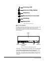
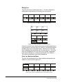
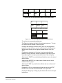
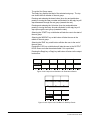
UP/DOWN VOLUME BUTTONS
Below each key display on lever key and pushbutton panels is a pair of
buttons to adjust the volume on that connection. The left button
reduces the volume and the right button increases the volume.
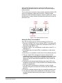
The volume buttons can also be used to release a telephone line in the
same way as the ‘TEL RELEASE’ function in the diagnostic menu (see
“Diagnostic Menu” on page 2-48). This function will only operate if the
label on the key is to a Tel-14 and remote telephone line release has
been enabled on the panel from ECS.
To release the telephone line both the up and down arrows are held
down by the user. The label display will change to say "TEL RELEAS"
and the telephone will be put back on hook and all latched keys to it on
the local system will be unlatched and so kill the routes to it. After
approximately 5 seconds the display will return to showing the
configured label.
If the panel does not have "Remote Line Release" configured then it
will send the call signal to the label.
1-13
Clear-Com
V-Series Panels User Guide
The volume buttons are also used to adjust some settings that are
accessed through the panel menu such as side tone gain (see “Level
Adjust Menu” in chapter 2).
ROTARY ENCODER
Beside each key display on rotary panels is a rotary encoder to adjust
the volume on that connection. Turning the rotary encoder clockwise
increases the volume and turning it anti-clockwise reduces the volume.
The rotary encoder can also be used to release a telephone line in the
same way as the ‘TEL RELEASE’ function in the diagnostic menu (see
“Diagnostic Menu” on page 2-48). This function will only operate if the
label on the key is to a Tel-14 and remote telephone line release has
been enabled on the panel from ECS.
To release the telephone line press and hold the rotary encoder switch.
The label display will change to say "TEL RELEAS" and the telephone
will be put back on hook and all latched keys to it on the local system
will be unlatched and so kill the routes to it. After approximately 5
seconds the display will return to showing the configured label.
If the panel does not have "Remote Line Release" configured then it
will send the call signal to the label.
The rotary encoder is also used to adjust some settings that are
accessed through the panel menu such as side tone gain (see “Level
Adjust Menu” in chapter 2) and scroll through lists.
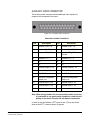
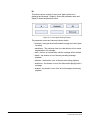
KEYPAD (2RU & DESKTOP PANELS)
The keypad on the 2RU lever key, pushbutton and rotary panels and
desktop panels may be used to access certain menu pages directly (as
a shortcut) and to enter dialcodes to dial out via a telephone interface
such as a TEL-14 interface unit.
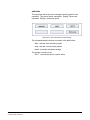
The menu shortcuts available from the keypad are:
• 1 - Dial Menu
• 2 - Local Exclusive
• 3 - Local page override
• 4 - Assignment Panel menu
• 5 - Local Key Assign menu
• 7 - Local Preferences menu
• # - Fast Key Assign menu
When the dialpad keys are used to access a menu function the menu
indicator lights.
1-14
Clear-Com
V-Series Panels User Guide
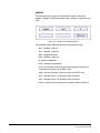
PTT OPERATION
PTT operation on V-Series panels may use either a PTT switch on the
panel headset or the auxiliary audio connector on the rear of the panel.
The operation of PTT on the V-series panels is determined by the
Headset PTT Function set in ECS. The Headset PTT Function may be
set to one of three options.
• No Function - headset PTT does not cause any talk or listen routes to
become active.
• Activate All Talk Keys - headset PTT will cause the audio routes on
all latched talk keys to become active. Unlatched talk keys and listen
keys will not become active. See sections below for details of latched
keys or pushbuttons.
• Activate Two-Way Radio Talk Keys - headset PTT will cause the
audio routes on all latched talk keys attached to two-way radios to
become active. Unlatched talk keys and listen keys will not become
active. See sections below for details of latched keys or
pushbuttons.
1-15
Clear-Com
V-Series Panels User Guide
LEVER KEY PANEL OPERATION
Lever keys can have both Talk and Listen labels assigned to the same
key in ECS and can be used as Talk or Listen keys depending on
whether the key is moved up or down. If the key is moved upwards
then the listen function is selected while if the key is moved down then
the talk function is selected.
The lever keys normally default to latching unless the non-latching
option is configured in ECS under Global Settings (Latch Disable set to
True) for the destination port. In the default state (latching) if the lever
key is momentarily pressed up or down it will latch whereas if it is held
in the talk or listen position for more than 200 ms it will not latch and
the connection will terminate as soon as the key is released.
When the key is inactive the talk/listen status indicator below the key
will display amber; when a talk path is active (key pressed down) the
status will indicate red and when a listen path is active (key pressed
up) the status will indicate green.
An incoming call to the panel will cause the reply key indicator to flash
red; to take the call press the reply key down or to clear the call press
the reply key up.
Lever Key Reply Key GPI Operation
If a footswitch (or other type of switch) is connected to GPI 3 which is
preassigned to the reply key the panel will clear the currently viewed
item on the reply stack on release of the switch. Please refer to the
section on “Opto-Isolated Inputs” on page 4-9 in this manual and the
ECS manual (part 810299Z) for details of the preassigned GPIs.
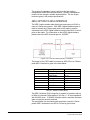
PUSHBUTTON PANEL OPERATIONS
Pushbuttons can only act as talk or listen keys depending on the
function assigned to them in ECS. The pushbuttons normally default
to latching unless the non-latching option is selected in ECS under
Global Settings (Latch Disable set to True) for the destination port. In
this case if the pushbutton is momentarily pressed it will latch whereas
if it is held for more than 200 ms it will not latch and the connection will
terminate as soon as the key is released.
When a pushbutton key is inactive (no talk or listen connection
established) the pushbutton will illuminate dim red or green depending
on whether it has been configured in ECS as a talk (red) or listen
(green) route or a talk and listen (amber) route.
When a pushbutton is pressed to establish a route the illumination will
change to bright red or green to indicate that a connection is
established. To cancel the connection press the button and it will
return to dim illumination.
1-16
Clear-Com
V-Series Panels User Guide
An incoming call will be signalled by a flashing red reply pushbutton; to
pick up the call press the reply pushbutton.
Pushbutton Reply Key GPI Operation
If a footswitch (or other type of switch) is connected to GPI 3 which is
preassigned to the reply key the panel will not clear the currently
viewed item on the reply stack on release of the switch. Please refer to
the section on “Opto-Isolated Inputs” on page 4-9 in this manual and
the ECS manual (part 810299Z) for details of the preassigned GPIs.
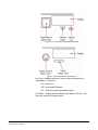
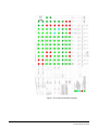
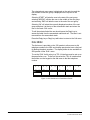
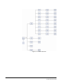
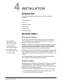
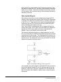
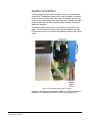
The audio block diagram for the V-Series panel is shown in Figure 1-20
below. This diagram shows all the allowed audio routes and valid
crosspoints allowed by the V-Series panel.
Note: Some of the audio paths shown on the block diagram are
only available via the audio mixer function in ECS.
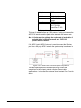
ROTARY PANEL OPERATIONS
Rotary panel keys can have both Talk and Listen labels assigned to
the same key in ECS. The Talk and Listen functions are split between
the rotary encoder and the button under the display (talk button). If the
rotary encoder is pressed then the listen function is selected and the
encoder illuminates green. If the button under the display is pressed
then the talk function is selected and the talk button illuminates red.
Key Operation
By default the talk label will be displayed on a key unless only a listen
label has been configured in which case the listen label will be
displayed. In assignment panel mode the talk labels are shown on
possible IFB destinations and the listen labels are shown when the
user is selecting an IFB source.
The rotary encoder and talk button normally default to latching unless
the non-latching option is selected in ECS under Global Settings
(Latch Disable set to True) for the destination port. In this case if the
rotary encoder or talk button is momentarily pressed it will latch
whereas if it is held for more than 200 ms it will not latch and the
connection will terminate as soon as the key is released.
When a rotary encoder is inactive (no listen connection established)
the centre of the rotary encoder will illuminate dim green. When a talk
button is inactive (no talk connection established) the talk button will
illuminate dim red. If the brightness control is turned down the dimmed
illumination of the rotary encoder and talk button will be extinguished.
When a rotary encoder is pressed to establish a listen route the
illumination will change to bright green. If a talk button is pressed to
establish a talk route the illumination will change to bright red to
indicate that a connection is established. To cancel the connection
Clear-Com
V-Series Panels User Guide
1-17
press the rotary encoder or talk button and it will return to dim
illumination.
An incoming call will be signalled by a flashing red reply key talk
button; to pick up the call press the reply key talk button.
Reply Key
Unlike lever key and pushbutton panels the Reply key on a rotary
panel can be overwritten with other talk and listen labels in ECS but is
not deleted. If the Reply key is overwritten the panel no longer has a
Reply key. If menu mode is entered and the reply key has been
overwritten Assignment Panel (AP) functions are disabled as the Reply
key is no longer available. If the labels placed on the Reply key are
removed in ECS the Reply key becomes available again and
Assignment Panel functions will be available.
The Reply key rotary encoder can be used to scroll through the Reply
key stack if more than one call is present on the answerback stack. To
move to the next call rotate the encoder clockwise; the move back to
the previous call rotate the encoder anticlockwise.
COM Keys
Rotary panels can have a special ‘COM’ key assigned to any key on
the panel including the Reply key in ECS. When the COM key is
selected the panel will enter Assignment Panel (AP) mode without
going into menu mode. If the COM key is placed on an expansion
panel selecting it will place the expansion panel and all other
expansion panels after it in the chain into AP mode. Panels that
precede it in the chain will not be placed in AP mode and can be used
normally.
Once in AP mode the COM key will behave in the same way as the
Reply key in AP mode allowing the user to configure IFBs,
Conferences and Fixed Groups as normal in AP mode.
If the Reply key has not been reassigned in ECS the talk button on the
reply key will also flash when in AP mode to mimic the COM key
status.
Rotary Panel IFB Operation
When a rotary panel key is assigned as an IFB source the rotary
encoder may be used to adjust the audio level sent from the panel to
the destination or the listen level at the panel.
If the call to the IFB destination is latched by momentarily pressing the
talk button the level of the audio sent to the IFB destination can be
adjusted by turning the rotary encoder.
If the call to the IFB destination is not latched (the talk button is held
down) the audio level is adjusted by pressing and turning the rotary
encoder.
1-18
Clear-Com
V-Series Panels User Guide
Figure 1-19: IFB Talk Level Adjust
Rotary Forced Listen Operation
Forced listen key operation on rotary panels differs from lever key and
pushbutton panels. A forced listen key on a rotary panel will show the
rotary encoder illuminated bright green to indicate active listen.
Pressing the rotary encoder configured as a forced listen will mute the
audio from the forced listen and the listen indicator will be
extinguished. Pressing the rotary encoder again will restore the forced
listen audio and the encoder will be illuminated green again.
Rotary Panel Reply Key GPI Operation
If a footswitch (or other type of switch) is connected to GPI 3 which is
preassigned to the reply key the panel will not clear the currently
viewed item on the reply stack on release of the switch. Please refer to
the section on “Opto-Isolated Inputs” on page 4-9 in this manual and
the ECS manual (part 810299Z) for details of the preassigned GPIs.
The audio block diagram for the V-Series panel is shown in Figure 1-20
below. This diagram shows all the allowed audio routes and valid
crosspoints allowed by the V-Series panel.
Note: Some of the audio paths shown on the block diagram are
only available via the audio mixer function in ECS.
Clear-Com
V-Series Panels User Guide
1-19
Figure 1-20: V-Series Audio Block Diagram
1-20
Clear-Com
V-Series Panels User Guide
2
This chapter describes
how to operate the
V-Series panels.
Note: V-Series panels
running application
code earlier than V1.73
need an IP license key
to enable IP operation.
V-series panels with
application code V1.73
or later include IP
operation as standard
OPERATION
PANEL MENU STRUCTURE
V-Series panels have a number of options accessed via a menu
system. To enter menu mode press the menu button on the front
panel to display the top level menu. The menu indicator LED will light
and various menu options will be displayed on the key displays.
Note: Access to the System Configuration, Local Preferences
and Diagnostic menus is set from ECS. Depending on the
ECS configuration, access to some or all of these menus
may be disabled on the panel.
To navigate the menu levels on lever key or pushbutton panels use the
lever key or push button corresponding to the display showing the
required menu item to select the option required. For rotary panels
use the talk button below the display showing the required menu item
to select the option required. The selected menu options will then be
displayed on the panel and the process is repeated until the panel item
to be set or adjusted is reached. To return to the previous menu use
the ‘REPLY’ key talk button which will display the name of the current
menu in inverse video.
For lever key panels in order to select a menu item the lever key
should be pressed down (Talk); the up (Listen) direction is not active
except in the case of the “View Keys” and “Local Keys” menus where
both up and down (Talk and Listen) key presses will select the menu
item.
To scroll through label lists use the up/down volume control buttons on
lever key and pushbutton panels or the rotary encoder on rotary
panels.
Up to eight expansion
panels may be attached
to a main panel. The
expansion panels must
be of the same type as
the main panel ie. lever
key, pushbutton or
rotary. Each expansion
panel provides an extra
twelve keys.
Some menus can be accessed directly using the keypad on the 2RU
and desktop panels. These are:
• 1 - Dial menu
• 2 - Local Exclusive
• 3 - Local page override
• 4 - Assignment Panel menu
• 5 - Local Key Assign menu
• 7- Local Preferences menu
• # - Fast Key Assign
Clear-Com
V-Series Panels User Guide
2-1
When menus are accessed directly via the keypad the blue menu LED
will light. To exit the menu options and return to the main page press
the ‘Menu’ key on the front panel. The menu LED will be extinguished.
FAST KEY ASSIGN
The fast key assign facility on V-Series panels with keypads allows
users to create and delete local key assignments. Before this facility
can be used it must be enabled for the panel in ECS using the
“Advanced Settings” facility (refer to the ECS manual part 810299Z for
details).
To enter fast key assign mode on a panel press the ‘#’ key on the
keypad. The Reply key will then display ‘FAST ASSN’ in inverted text.
FAST ASSN
Label 01
Label 03
Label 05
Label 07
Label 09
Label 02
Label 04
Label 06
Label 08
Label 10
Figure 2-1: Fast Key Assign for Rack Mount Panels
Label 01
Label 02
Label 03
Label 04
Label 05
Label 06
Label 07
Label 08
Label 09
Label 10
FAST ASSN
Figure 2-2: Fast Key Assign for Desktop Panels
Enter the destination panel port number as a string of 3 digits which
will be echoed on the reply key display. The destination port numbers
start at 600; port numbers below 600 are not valid. If a multiple matrix
system is being used the destination port number must be prefixed by
the system number. For example, if a single matrix is being used the
system number prefix can be omitted and just the destination port
number specified e.g. 609. In a system with three matrices port 609 on
system 2 would be specified as 2609. Once a valid destination port
number has been input the talk label for the destination port will be
displayed on the reply key after the destination port number. If the
destination port number entered is invalid the word ‘INVALID’ will be
2-2
Clear-Com
V-Series Panels User Guide
displayed in the reply key. Press the ‘#’ key to enter a new port
number.
The destination port input must be terminated by pressing the ‘*’ key.
The full ten character label of the destination port will be displayed on
the reply key and any keys on the current page that are available to be
assigned will flash. If the destination is a member of a valid local sort
group all the other valid members of that sort group can be accessed
by using the up/down buttons or rotary encoder on the reply key to
scroll through the sort group. Any other member of the sort group can
be selected in this way for assignment.
If the destination port is a member of a sort group that is blocked for
the panel the word ‘BLOCKED’ will be displayed in the reply key. Sort
group permissions are set for panels in ‘Advanced Settings’ under
‘Soft Mode Options’ (please refer to the ECS manual part 810299Z for
further information).
Select one of the flashing keys either by pressing the button (push
button panel) or pressing the key down (lever key panel) or pressing
the talk button (rotary panel) and the selected destination port will be
assigned to that key. When a key has been assigned the Talk/Listen
attributes will be set to those defined by ECS. The assigned key
attributes can be changed later from the local panel menu. To exit
assign mode press the ‘Menu’ button. The sequence is illustrated in
Figure 2-3.
Clear-Com
V-Series Panels User Guide
2-3
Figure 2-3: Basic Steps to Fast Assign a Key
To delete a key assignment press the ‘#’ key followed by the ‘*’ key.
The reply key will display ‘DELETE?’ and all the keys that can be
deleted will flash. Press the button (push button panel) or press the
key down (lever key panel) or press the talk button (rotary panel) on
any of the flashing keys to have their assignments deleted. To exit
delete mode press the ‘Menu’ button.
TOP LEVEL MENU
To enter the menu system press the ‘MENU’ button on the front panel
to display the top level menu. The blue LED will light to indicate the
panel is now in menu mode. If the menu button is pressed when the
panel is already in menu mode then the panel will exit menu mode and
the LED will be extinguished.
2-4
Clear-Com
V-Series Panels User Guide
SYS INFO
LOCAL PREF SYS CONFIG
DIAL
MENU
MESSAGE
DIAGNOSTIC LOCAL PAGE SUPERVISE
CALL
LOCAL EXCL ASSNMT PNL
Figure 2-4: Main Menu Display for Rack Mount Panels
DIAL
LOCAL EXCL ASSNMT PNL
DIAGNOSTIC LOCAL PAGE SUPERVISE
SYS INFO
LOCAL PREF SYS CONFIG
MENU
MESSAGE
CALL
Figure 2-5: Main Menu Display for Desktop Panels
The main menu options are:
• SYS INFO - access to menu options allowing panel keys and
nearby panels to be viewed.
• LOCAL PREF - access to the menu for setting up preferences
on the panel such as brightness levels, timeouts and audio
levels.
• SYS CONFIG - provides access to the local panel
configuration, input levels adjustment and output levels
adjustment.
• DIAL - allows manual dialling on panel types without a
keypad.
• LOCAL EXCL - temporarily deactivates latched keys during
Talk or Listen. Requires the matrix to be online.
• ASSNMT PNL - allows keys to be assigned locally to IFBs,
Party Lines and Fixed Groups.
• MESSAGE - Record and review outgoing audio message.
• CALL - display the CALL menu allowing labels to placed on
the answerback stack to create a temporary user key.
• DIAGNOSTIC - access the diagnostic menu to display system
information, reset the panel and test audio links.
Clear-Com
V-Series Panels User Guide
2-5
• LOCAL PAGE - allows the user to override destination volume
settings to talk to these panels.
• SUPERVISE - puts the panel into supervisor mode to
supervise other panels. The supervise option must be
enabled for the panel in ECS for this menu option to be
displayed. To enable the supervise option a features
passcode must be entered into the “System Access Codes”
tab under “System Preferences” (see the ECS manual for
details). Please contact Clear-Com sales for further
information.
To exit the menu press the Reply key (‘MENU’) or press the menu
button again. The blue menu LED will be extinguished.
SYSTEM INFORMATION MENU
To select the ‘SYS INFO’ display use the lever key or pushbutton or
talk button to display the system information menu. This menu allows
the user to view all the Party Lines and Fixed Groups programmed on
the local system.
VIEW KEYS
PARTY LINE FIXED GRP
SYS INFO
MONITORS
NEAR PNLS
FL SOURCE FL DEST
Figure 2-6: System Information Display for Rack Mount Panels
VIEW KEYS
PARTY LINE
NEAR PNLS
FIXED GRP
MONITORS
FL SOURCE
FL DEST
SYS INFO
Figure 2-7: System Information Display for Desktop Panels
The SYS INFO menu provides access to the following functions:
• VIEW KEYS - view the panel key setups.
• PARTY LINE - list of Party Lines available and members of
the Party Lines.
2-6
Clear-Com
V-Series Panels User Guide
• FIXED GRP - list of Fixed Groups available and members of
the Fixed Groups.
• NEAR PNLS - list of panels configured as nearby panels in
ECS.
• MONITORS - list of panels monitoring this panel.
• FL SOURCE - list of forced listen sources available to the
panel.
• FL DEST - list of forced listen destinations available to the
panel.
To exit system information mode and return to main menu mode press
the Reply key or Reply key talk button (‘SYS INFO’). The main menu
will be redisplayed.
View Keys Menu
To enter the ‘VIEW KEYS’ menu use the lever key or pushbutton or
talk button to select the view keys function. The first level of the key
information menus will be displayed.
Label 01
Label 02
Label 04
Label 06
Label 08
Label 10
VIEW KEYS
Label 03
Label 05
Label 07
Label 09
Label 11
Figure 2-8: View Keys Display for Rack Mount Panels
Label 01
Label 02
Label 03
Label 04
Label 05
Label 06
Label 07
Label 08
Label 09
VIEW KEYS
Label 10
Label 11
Figure 2-9: View Keys Display for Desktop Panels
Use the up/down volume buttons or rotary encoder on the Reply key
(‘VIEW KEYS’) to scroll through the list of key labels.
Each label displayed allows access to the configuration information for
that label. To display the information use the corresponding talk/listen
Clear-Com
V-Series Panels User Guide
2-7
key or talk button to select the label and the information will be
displayed. To exit view keys menu and return to the system
information menu press the Reply key or Reply key talk button (‘VIEW
KEYS’). The system information menu will be redisplayed.
Key Info Menu
Label 01
Label 01 Alias Attributes
KEY INFO
Sys Name
Label entity
LIST
Figure 2-10: Key Info Display for Rack Mount Panels
Attributes
Label 01
Label 01 Alias Sys Name
KEY INFO
Label entity
LIST
Figure 2-11: Key Info Display for Desktop Panels
The items in italics are system and configuration dependant as follows:
• Attributes - may be Talk, Talk + Lstn, Talk + FL, Dual T+L,
Listen or Force Lstn
• Sys Name - name of the system that the entity the label refers
to is attached to
• Label Entity - type of label, may be PORT, PL, IFB, FG.
CONTROL
• LIST - this option will be displayed if the label is a fixed group.
Pressing this key will display a list of the fixed group members
(see “Fixed Group Menu”).
To exit the key info menu and return to the view keys menu press the
Reply key or Reply key talk button (‘KEY INFO’). The view keys menu
will be redisplayed.
2-8
Clear-Com
V-Series Panels User Guide
Party Line Menu
The party line menu option displays the party lines available to the
panel.
VIEW PL
PL01
PL03
PL05
PL07
PL09
PL02
PL04
PL06
PL08
PL010
Figure 2-12: Party Line Menu for Rack Mount Panels
PL01
PL02
PL03
PL04
PL05
PL06
PL07
PL08
PL09
PL010
VIEW PL
Figure 2-13: Party Line Menu for Desktop Panels
Using the up/down volume buttons or the rotary encoder on the Reply
key (‘VIEW PL’) will scroll through the available party lines on the panel
display. Selecting one of the party lines will display the membership
menu for that party line. To exit the view party line menu and return to
the system information menu press the Reply key or Reply key talk
button (‘VIEW PL’). The system information menu will be redisplayed.
Label 01
Label 03
Label 05
Label 07
Label 09
PL MEMBERS Label 02
Label 04
Label 06
Label 08
Label 10
PL01
Figure 2-14: Party Line Labels for Rack Mount Panels
Clear-Com
V-Series Panels User Guide
2-9
Label 01
Label 02
Label 03
Label 04
Label 05
Label 06
PL01
Label 07
Label 08
PL MEMBERS Label 09
Label 10
Figure 2-15: Party Line Labels for Desktop Panels
Using the volume up/down buttons or the rotary encoder on the Reply
key (‘PL MEMBERS’) will scroll through the list of party line members.
To exit the party line members menu and return to the view party line
menu press the Reply key or Reply key talk button (‘PL MEMBERS’).
The view party line menu will be redisplayed.
Where members have been assigned to a Party Line using Production
Maestro rather than ECS these members will not be displayed. This is
due to such assignments being temporary rather than fixed in the ECS
configuration.
Fixed Group Menu
The Fixed Group menu displays a list of all the Fixed Groups available
to the panel.
VIEW FG
FxG 01
FxG 03
FxG 05
FxG 07
FxG 09
FxG 02
FxG 04
FxG 06
FxG 08
FxG 10
Figure 2-16: Fixed Group List for Rack Mount Panels
2-10
Clear-Com
V-Series Panels User Guide
FxG 01
FxG 02
FxG 03
FxG 04
FxG 05
FxG 06
FxG 07
FxG 08
FxG 09
FxG 10
VIEW FG
Figure 2-17: Fixed Group Menu for Desktop Panels
Using the Reply key (‘VIEW FG’) up/down volume buttons or rotary
encoder will scroll through the available fixed groups on the panel
display. Selecting one of the fixed groups will display the membership
for that fixed group. To exit the view fixed groups menu and return to
the system information menu press the Reply key or Reply key talk
button (‘VIEW FG’). The system information menu will be redisplayed.
Label 01
Label 03
Label 05
Label 07
Label 09
FG MEMBERS Label 02
Label 04
Label 06
Label 08
Label 10
FxG 01
Figure 2-18: Fixed Group Labels for Rack Mount Panels
Label 01
Label 02
Label 03
Label 04
Label 05
Label 06
FxG 01
Label 07
Label 08
FG MEMBERS Label 09
Label 10
Figure 2-19: Fixed Group Labels for Desktop Panels
Using the volume up/down buttons or rotary encoder on the Reply key
(‘FG MEMBERS’) will scroll through the list devices that are members
of the fixed group. To exit the fixed group members menu and return
Clear-Com
V-Series Panels User Guide
2-11
to the view fixed group menu press the Reply key or Reply key talk
button (‘FG MEMBERS’). The view fixed group menu will be
redisplayed.
Nearby Panels Menu
Selecting the ‘NEAR PNLS’ option on the main menu will display the
labels associated with panels configured as ‘Nearby Panels’ in ECS.
Panels designated as ‘Nearby Panels’ are within hearing distance of
each other and an audio link between panels could result in an audio
feedback loop (‘howlround’). Audio paths to panels designated as
nearby panels cannot be established.
NEAR PNLS
Label 01
Label 03
Label 05
Label 07
Label 09
Label 02
Label 04
Label 06
Label 08
Label 10
Figure 2-20: Nearby Panels Display for Rack Mount Panels
Label 01
Label 02
Label 03
Label 04
Label 05
Label 06
Label 07
Label 08
Label 09
Label 10
NEAR PNLS
Figure 2-21: Nearby Panels Display for Desktop Panels
Using the up/down volume buttons or rotary encoder on the Reply key
(‘NEAR PNLS’) will scroll through the list of nearby panels. To exit the
nearby panels menu and return to the system information menu press
the Reply key or Reply key talk button (‘NEAR PNLS’). The system
information menu will be redisplayed.
Monitor Menu
The ‘MONITOR’ menu will display a list of the ports monitoring the
current panel.
2-12
Clear-Com
V-Series Panels User Guide
MONITORS
Label 01
Label 03
Label 05
Label 07
Label 09
Label 02
Label 04
Label 06
Label 08
Label 10
Figure 2-22: Monitor Menu for Rack Mount Panels
Label 01
Label 02
Label 03
Label 04
Label 05
Label 06
Label 07
Label 08
Label 09
Label 10
MONITORS
Figure 2-23: Monitor Menu for Desktop Panels
Using the up/down buttons or rotary encoder on the Reply key
(‘MONITORS’) will scroll through the list of monitoring ports. To exit
the monitors menu and return to the system information menu press
the Reply key or Reply key talk button (‘MONITORS’). The system
information menu will be redisplayed.
Forced Listen Source Menu
The ‘FL SOURCE’ menu allows the operator to list all the forced listen
sources configured in the system. A forced listen is a permanently
enabled audio path set up in ECS between a source and a destination
allowing the destination to listen to the source without the source
having to activate a talk key. For details on setting up a forced listen in
ECS please refer to “Panel Programming” in the ECS manual.
FL SOURCE
Label 01
Label 03
Label 05
Label 07
Label 09
Label 02
Label 04
Label 06
Label 08
Label 10
Figure 2-24: Forced Listen Source Interfaces for Rack Mount Panels
Clear-Com
V-Series Panels User Guide
2-13
Label 01
Label 02
Label 03
Label 04
Label 05
Label 06
Label 07
Label 08
Label 09
Label 10
FL SOURCE
Figure 2-25: Forced Listen Source Interfaces for Desktop Panels
Using the up/down volume buttons or rotary encoder on the Reply Key
(‘FL SOURCE’) will scroll through the list of forced listen sources. To
exit the forced listen source menu and return to the system information
menu press the Reply key or Reply key talk button (‘FL SOURCE’).
The system information menu will be redisplayed.
Forced Listen Destination Menu
Pressing the ‘FL DEST’ key or talk button will display all the forced
listen destinations configured on the panel.
FL DEST
Label 01
Label 03
Label 05
Label 07
Label 09
Label 02
Label 04
Label 06
Label 08
Label 10
Figure 2-26: Forced Listen Destinations for Rack Mount Panels
Label 01
Label 02
Label 03
Label 04
Label 05
Label 06
Label 07
Label 08
Label 09
Label 10
FL DEST
Figure 2-27: Forced Listen Destinations for Desktop Panels
2-14
Clear-Com
V-Series Panels User Guide
Using the volume up/down buttons or rotary encoder on the Reply Key
(‘FL DEST’) will scroll through the list of forced listen destinations. To
exit the forced listen destination menu and return to the system
information menu press the Reply key or Reply key talk button (‘FL
DEST’). The system information menu will be redisplayed.
LOCAL PREFERENCES MENU
Selecting the ‘LOCAL PREF’ option on the main menu will display
panel setups that may be changed locally rather than by ECS. If the
PIN code has been enabled in ECS the panel will request PIN code
entry before allowing access to the local preferences menu.
3
4
LOCAL PREF ENTER PIN
****
0
1
2
5
6
7
8
9
*
#
Figure 2-28: Local Preferences PIN Code Request
1
2
3
4
5
6
7
8
9
0
*
#
ENTER PIN
****
LOCAL PREF
Figure 2-29: Local Preferences PIN Code Request
On lever key and pushbutton panels enter the PIN code using the
volume up/down buttons under each number.
Clear-Com
V-Series Panels User Guide
2-15
Figure 2-30: Lever and Pushbutton PIN Code Input
On rotary panels press the rotary encoder to select the left hand digit
and the talk button to select the right hand digit in the display.
Figure 2-31: Rotary Control PIN Code Input
The PIN code digits will be echoed as ‘X’ in the PIN code entry window.
TIMEOUTS
LEVEL ADJ
LOCAL PREF
BRIGHTNESS
RESET XPTS
Figure 2-32: Local Preferences Display for Rack Mount Panels
2-16
Clear-Com
V-Series Panels User Guide
BRIGHTNESS LEVEL ADJ
TIMEOUTS
LOCAL PREF
RESET XPTS
Figure 2-33: Local Preferences Display for Desktop Panels
The panel menu items are:
• TIMEOUTS - displays the timeouts setting menu.
• LEVEL ADJ - displays the menu to set the audio levels for the
microphones, headset and loudspeaker.
• BRIGHTNESS- displays the brightness setup menu that
allows the brightness of all labels and LEDs to be adjusted.
• RESET XPTS - displays the menu for resetting the panel
crosspoints to default level.
To exit the local preferences menu and return to the main menu press
the Reply key or Reply key talk button (‘LOCAL PREF’). The main
menu will be redisplayed.
Timeouts
Selecting ‘TIMEOUTS’ from the local preferences menu will display the
answerback and Listen Again timeouts setup menu.
The answerback timeout controls the length of time an unanswered
call remains in the reply key stack. If the value is set to ‘OFF’ (0
seconds) or the function is disabled calls will remain in the reply key
stack until actioned.
The Listen Again timeout controls the length of time before recorded
messages are auto deleted and may be set to a value of 0 to 99
minutes in units of 1 minute. If the timeout is set to 99 the messages
are not auto-deleted. If the timeout is set to 0 the Listen Again facility
is disabled so no audio is recorded. This timeout can be used to
ensure that recorded conversations are not left on a panel where they
may be accessed later by other operators.
Clear-Com
V-Series Panels User Guide
2-17
ANSWERBACK
TIMEOUTS
10
DISABLE
10
MSG A DEL
Figure 2-34: Timeout Display for Rack Mount Panels
ANSWERBACK MSG A DEL
10
10
ENABLE
TIMEOUTS
Figure 2-35: Timeout Display for Desktop Panels
• ANSWERBACK - allows the panel answerback timeout to be
set to a value from 0 (OFF) to 60 seconds in 10 second steps.
• DISABLE - selecting this items disables answerback timeout.
• MSG A DEL - allows the panel Listen Again timeout to be set
to a value of 0 to 99 minutes. If the timeout is set to 0 the
Listen Again facility is disabled (no audio recorded). If the
timeout is set to 99 the messages are not auto-deleted.
To exit the time-outs menu and return to the local preferences menu
press the Reply key or Reply key talk button (‘TIMEOUTS’). The local
preferences menu will be redisplayed.
2-18
Clear-Com
V-Series Panels User Guide
Level Adjust Menu
Selecting the ‘LEVEL ADJ’ menu item in the local preferences menu
will display the audio levels setup menu.
LEVEL ADJ
GN MIC 40
HS MIC 40
HS2MIC 40
LS DIM -12
L SIDETONE
R SIDETONE
L2 SIDETONE R2 SIDETONE
--------
-----
---------
-------
Figure 2-36: Level Adjust Display for Rack Mount Panels
HS2MIC 40
L2SIDETONE R2SIDETONE
---
-------
GN MIC 40
HS MIC 40
LS DIM -12
LEVEL ADJ
L SIDETONE
R SIDETONE
-----
-----
Figure 2-37: Level Adjust Display for Rack Desktop Panels
This menu adjusts the audio gain values for gooseneck panel
microphone and headset microphones to preset levels of 20, 40, 50,
60, 70 or 80 db. The sidetone levels can be set for the first headset
(front panel connector) and the second headset (auxiliary audio
connector).
• GN MIC - gooseneck microphone gain setting. This is
adjusted using the up/down buttons or rotary encoder.
• HS MIC - headset microphone gain setting. This is adjusted
using the up/down buttons or rotary encoder.
• HS2MIC - second headset microphone gain setting. This is
adjusted using the up/down buttons or rotary encoder.
• LS DIM - how much the loudspeaker is dimmed when a talk
key is pressed (-70dB, -20dB, -12dB, -6dB, -3dB, 0dB). This
is adjusted using the up/down button or rotary encoder.
• L SIDETONE - first headset left sidetone level. The key
status (lever key) or pushbutton or talk button (rotary) is
illuminated red when the left sidetone is on. To toggle left
sidetone between ON and OFF press the pushbutton or press
the lever key down or press the talk button (rotary). Use the
Clear-Com
V-Series Panels User Guide
2-19
up/down buttons or rotary encoder to adjust the left sidetone
level. The default sidetone level is -9dB, the minimum level is
-15.5dB.
• R SIDETONE - first headset right sidetone level. The key
status (lever key) or pushbutton or talk button (rotary) is
illuminated red when the right sidetone is on. To toggle right
sidetone between ON and OFF press the key pushbutton or
press the lever key down or press the talk button (rotary).
Use the up/down buttons or rotary encoder to adjust the right
sidetone level. The default sidetone level is -9dB, the
minimum level is -15.5dB.
• L2SIDETONE - second headset left sidetone level. The key
status (lever key) or pushbutton or talk button (rotary) is
illuminated red when the left sidetone for the second headset
is on. To toggle left sidetone between ON and OFF press the
key pushbutton or press the lever key down or press the talk
button (rotary). Use the up/down buttons or rotary encoder to
adjust the second headset left sidetone level. The default
sidetone level is -9dB, the minimum level is -15.5dB.
• R2SIDETONE - second headset right sidetone level. The key
status (lever key) or pushbutton or talk button (rotary) is
illuminated red when the right sidetone for the second
headset is on. To toggle right sidetone between ON and OFF
press the key pushbutton or press the lever key down or
press the talk button (rotary). Use the up/down buttons or
rotary encoder to adjust the second headset right sidetone
level. The default sidetone level is -9dB, the minimum level is
-15.5dB.
Note: When a monaural headset is being used only the headset
left sidetone adjust operates; the right sidetone adjust has
no effect.
To exit the level adjust menu and return to the local preferences menu
press the Reply key or Reply key talk button (‘LEVEL ADJ’). The local
preferences menu will be redisplayed.
2-20
Clear-Com
V-Series Panels User Guide
Brightness Menu
Selecting the ‘BRIGHTNESS’ item in the local preferences menu will
display the brightness adjustment menu.
brightness
brightness
brightness
brightness
brightness
brightness
BRIGHTNESS brightness
brightness
brightness
brightness
brightness
Figure 2-38: Brightness Adjustment Display for Rack Mount Panels
brightness
brightness
brightness
brightness
brightness
brightness
brightness
brightness
brightness
BRIGHTNESS brightness
brightness
Figure 2-39: Brightness Adjustment Display for Desktop Panels
Using the up/down buttons or rotary encoder on the reply key will alter
the brightness of the displays. The displays will automatically dim after
the time limit set in ECS Panel Options (from 0 to 60 minutes) where 0
minutes sets the panel display to dim mode permanently. After a
further period the display will change to provide a screensaver to
increase the lifetime of the displays. To exit the brightness menu and
return to the local preferences menu press the Reply key or Reply key
talk button (‘BRIGHTNESS’). The local preferences menu will be
redisplayed.
Clear-Com
V-Series Panels User Guide
2-21
Messages Menu
Selecting ‘MESSAGE’ from the local preferences menu displays the
message menu allowing an outgoing messages to be recorded,
reviewed, output to audio and erased.
MESSAGE
RECORD
REVIEW
PLAY
ERASE
Figure 2-40: Messages for Rack Mount Panels
MESSAGE
RECORD
REVIEW
PLAY
ERASE
Figure 2-41: Messages for Desktop Panels
The following functions are available for outgoing messages on
V-Series panels:
• RECORD - when the RECORD button is pressed and held the text
will invert and up to 10 seconds of audio from the microphone can
be recorded into an audio file on the panel.
• REVIEW when the REVIEW button is pressed the text will invert
and the outgoing message will be played to the currently selected
output device (Headset or Loudspeaker).
• PLAY - when the PLAY button is pressed the text will invert and
the outgoing message will be output to the route configured by
ECS. This will normally be Matrix 1 or Matrix 2 but may be the
EXT1 or EXT2 output.
• ERASE - when the ERASE button is pressed the current outgoing
message will be erased.
To exit the message menu and return to the local preferences menu
press the Reply key or Reply key talk button (‘MESSAGE’). The local
preferences menu will be redisplayed.
2-22
Clear-Com
V-Series Panels User Guide
Once recorded the message can be used by selecting a talk path set
up on the panel, entering the message menu and pressing ‘PLAY’.
The recorded message will then be output to the talk path until
cancelled. If the talk path connects to another panel it should be heard
as an incoming talk on the target panel and allows audio paths to be
verified between ports.
Reset Crosspoints Menu
Reset Xpts
Selecting ‘RESET XPTS’ from the local preferences menu displays the
reset crosspoints menu offering the option to reset the panel
crosspoints to their default levels.
RESET XPT
RESET XPTS
YES
LEVELS
NO
Figure 2-42: Reset Crosspoints Display for Rack Mount Panels
RESET XPT
RESET XPTS
YES
LEVELS
NO
Figure 2-43: Reset Crosspoints Display for Desktop Panels
Press the ‘YES’ key or pushbutton or talk button to reset the panel
crosspoint levels to their default settings or the ‘NO’ key to cancel the
operation and return the user to the local preferences menu. To exit
the reset crosspoints menu and return to the local preferences menu
press the Reply key or Reply key talk button (‘RESET XPTS’). The
local preferences menu will be redisplayed.
Clear-Com
V-Series Panels User Guide
2-23
SYSTEM CONFIGURATION MENU
Selecting ‘SYS CONFIG’ from the top level menu will display the
system configuration menu for the panel. If the PIN code has been
enabled in ECS the panel will request PIN code entry before allowing
access to the system configuration menu.
0
2
1
SYS CONFIG
3
4
ENTER PIN
****
5
6
7
8
9
*
#
Figure 2-44: System Configuration PIN Code Request
1
2
3
4
5
6
7
8
9
0
*
#
ENTER PIN
****
SYS CONFIG
Figure 2-45: System Configuration PIN Code Request
On lever key or pushbutton panels enter the PIN code using the
volume up/down buttons under each number. On rotary panels press
the rotary encoder to select the left hand digit and the talk button to
select the right hand digit in the display. The PIN code digits will be
shown as ‘*’ in the PIN code entry window.
PARTY LINE
FIXED GRP
SYS CONFIG
FORCE LSTN
LOCAL PNL
REMOTE PNL
INPUT LVLS
OUTPUT LVL
Figure 2-46: System Configuration Menu for Rack Mount Panels
2-24
Clear-Com
V-Series Panels User Guide
PARTY LINE
FIXED GRP
FORCE LSTN
LOCAL PNL
SYS CONFIG
INPUT LVLS
REMOTE PNL OUTPUT LVL
Figure 2-47: System Configuration Menu for Desktop Panels
• PARTY LINE - displays the Party Line configuration menu.
This allows interfaces and panels to be assigned to a party
line.
• FIXED GRP - displays the Fixed Group configuration menu.
This allows interfaces and panels to be assigned to a fixed
group.
• REMOTE PNL - displays the Remote Panel configuration
menu.
• LOCAL PNL - displays the menu to configure the local panel
and modify the attributes of the keys.
• FORCE LSTN - displays the Forced Listen configuration
menu. This allows sources and destinations configured as
keys on the current panel to be set as forced listens.
• INPUT LVLS - displays the menu to set input audio levels.
• OUTPUT LVL - displays the menu to set output audio levels.
To exit the system configuration menu and return to the main menu
press the Reply key or Reply key talk button (‘SYS CONFIG’). The
main menu will be redisplayed.
Clear-Com
V-Series Panels User Guide
2-25
Party Line
The party line menu will allow party lines 1 - 10 to be configured by
adding panels and interfaces to the party lines as members.
PL CONFIG
PL01
PL03
PL05
PL07
PL09
PL02
PL04
PL06
PL08
PL010
Figure 2-48: Party Line Menu for Rack Mount Panels
PL01
PL02
PL03
PL04
PL05
PL06
PL07
PL08
PL09
PL010
PL CONFIG
Figure 2-49: Party Line Menu for Desktop Panels
Using the up/down volume buttons (lever key or pushbutton panels) or
rotary encoder on the Reply Key (‘PL CONFIG’) will scroll through the
available party lines on the panel display. Selecting one of the party
lines will display the membership menu for that party line. To exit the
party line configuration menu and return to the system configuration
menu press the Reply key or Reply key talk button (‘PL CONFIG’).
The system configuration menu will be redisplayed.
Party Line Membership Menu
The party line membership menu allows interfaces and panels to be
added to or removed from a party line.
INTERFACES PANELS
PL01
PL MEMBERS
Figure 2-50: Party Line Membership for Rack Mount Panels
2-26
Clear-Com
V-Series Panels User Guide
PL01
INTERFACES PANELS
PL MEMBERS
Figure 2-51: Party Line Membership for Desktop Panels
Selecting ‘INTERFACES’ will display the list of interfaces that may be
members of the party line. To exit the party line members menu and
return to the party line configuration menu press the Reply key or
Reply key talk button (‘PL MEMBERS’). The party line configuration
menu will be redisplayed.
PL INTS
Label 01
Label 03
Label 05
Label 07
Label 09
Label 02
Label 04
Label 06
Label 08
Label 10
Figure 2-52: Party Line Labels for Rack Mount Panels
Label 01
Label 02
Label 03
Label 04
Label 05
Label 06
Label 07
Label 08
Label 09
Label 10
PL INTS
Figure 2-53: Party Line Labels for Desktop Panels
Using the volume up/down buttons (lever key and pushbutton panels)
or rotary encoder on the Reply Key (‘PL INTS’) will scroll through the
list of possible interfaces. If an interface is a member of the party line a
selection bar will be displayed under the interface name. To select or
Clear-Com
V-Series Panels User Guide
2-27
deselect a label press the lever key/button or talk button next to the
required label and the interface will either be added to the party line
membership or removed from the party line membership. To exit the
party line interfaces menu and return to the party line members menu
press the Reply key or Reply key talk button (‘PL INTS’). The party
line members menu will be redisplayed.
Selecting ‘PANELS’ from the party line members menu will display a
list of panels that may be members of the party line. To exit the party
line members menu and return to the party line configuration menu
press the Reply key or Reply key talk button (‘PL MEMBERS’). The
party line configuration menu will be redisplayed.
PL PANELS
Label 01
Label 03
Label 05
Label 07
Label 09
Label 02
Label 04
Label 06
Label 08
Label 10
Figure 2-54: Party Line Labels for Rack Mount Panels
Label 01
Label 02
Label 03
Label 04
Label 05
Label 06
Label 07
Label 08
Label 09
Label 10
PL PANELS
Figure 2-55: Party Line Labels for Desktop Panels
Using the volume up/down buttons (lever key and pushbutton panels)
or the rotary encoder on the Reply Key (‘PL PANELS’) will scroll
through the list of possible panels. If a panel is a member of the party
line a selection bar will be displayed under the panel name. To select
or deselect a panel press the lever key/button or talk button next to the
required label and the panel will either be added to the party line
membership or removed from the party line membership. To exit the
party line panels menu and return to the party line members menu
press the Reply key or Reply key talk button (‘PL PANELS’). The party
line members menu will be redisplayed.
2-28
Clear-Com
V-Series Panels User Guide
Fixed Group
The Fixed Group menu will allow fixed groups to be configured by
adding panels and interfaces to the fixed groups as members.
FG CONFIG
FxG 01
FxG 03
FxG 05
FxG 07
FxG 09
FxG 02
FxG 04
FxG 06
FxG 08
FxG 10
Figure 2-56: Fixed Group Menu for Rack Mount Panels
FxG 01
FxG 02
FxG 03
FxG 04
FxG 05
FxG 06
FxG 07
FxG 08
FxG 09
FxG 10
FG CONFIG
Figure 2-57: Fixed Group Menu for Desktop Panels
Use the volume up/down buttons (lever key or pushbutton panels) or
rotary encoder on the Reply Key (‘FG CONFIG’) to scroll through the
available fixed groups on the panel display. Selecting one of the fixed
groups will display the membership menu for that fixed group. To exit
the fixed group configuration menu and return to the system
configuration menu press the Reply key or Reply key talk button (‘FG
CONFIG’). The system configuration menu will be redisplayed.
Fixed Group Membership Menu
When a fixed group is selected from the Fixed Group configuration list
the membership editing menu will be displayed. To exit the fixed group
members menu and return to the fixed group configuration menu press
the Reply key or Reply key talk button (‘FG MEMBERS’). The fixed
group configuration menu will be redisplayed.
Clear-Com
V-Series Panels User Guide
2-29
INTERFACES PANELS
FxG01
FG MEMBERS
Figure 2-58: Fixed Group Membership for Rack Mount Panels
FxG01
INTERFACES PANELS
FG MEMBERS
Figure 2-59: Fixed Group Membership for Desktop Panels
Selecting ‘INTERFACES’ will display a list of the interfaces that may be
members of the fixed group.
FG INTS
Label 01
Label 03
Label 05
Label 07
Label 09
Label 02
Label 04
Label 06
Label 08
Label 10
Figure 2-60: Fixed Group Labels for Rack Mount Panels
2-30
Clear-Com
V-Series Panels User Guide
Label 01
Label 02
Label 03
Label 04
Label 05
Label 06
FxG 01
Label 07
Label 08
FG INTS
Label 09
Label 10
Figure 2-61: Fixed Group Labels for Desktop Panels
Using the volume up/down buttons (lever key or pushbutton panels) or
rotary encoder on the Reply Key (‘FG INTS’) will scroll through the list
of possible interfaces. If an interface is a member of the fixed group a
selection bar will be displayed under the label name. To select or
deselect an interface press the lever key/button or talk button next to
the required interface and the interface will either be added to the fixed
group membership or removed from the fixed group membership. To
exit the fixed group interfaces menu and return to the fixed group
members menu press the Reply key or Reply key talk button (‘FG
INTS). The fixed group members menu will be redisplayed.
Selecting ‘PANELS’ will display a list of the panels that may be
members of the fixed group.
FG PANELS
Label 01
Label 03
Label 05
Label 07
Label 09
Label 02
Label 04
Label 06
Label 08
Label 10
Figure 2-62: Fixed Group Labels for Rack Mount Panels
Clear-Com
V-Series Panels User Guide
2-31
Label 01
Label 02
Label 03
Label 04
Label 05
Label 06
FxG 01
Label 07
Label 08
FG PANELS
Label 09
Label 10
Figure 2-63: Fixed Group Labels for Desktop Panels
Using the volume up/down buttons (lever key or pushbutton panels) or
rotary encoder on the Reply key (‘FG PANELS’) will scroll through the
list of possible panels. If a panel is a member of the fixed group a
selection bar will be displayed under the panel name. To select or
deselect a panel press the lever key/button or talk button next to the
required panel and the panel will either be added to the fixed group
membership or removed from the fixed group membership. To exit the
fixed group panels menu and return to the fixed group members menu
press the Reply key or Reply key talk button (‘FG PANELS’). The fixed
group members menu will be redisplayed.
Local Panel Menu
Selecting the ‘LOCAL PNL’ item in the system configuration menu will
display the local panel configuration menu.
LOCAL KEYS ATTRIBUTES
LOCAL PNL
Figure 2-64: Local Panel Menu for Rack Mount Panels
2-32
Clear-Com
V-Series Panels User Guide
LOCAL KEYS ATTRIBUTES
LOCAL PNL
Figure 2-65: Local Panel Menu for Desktop Panels
• LOCAL KEYS - displays the menu to assign keys on the
panel.
• ATTRIBUTES - displays the attributes menu to allow the
properties of the panel keys to be set.
To exit the local panel menu and return to the system configuration
menu press the Reply key or Reply key talk button (‘LOCAL PNL’).
The system configuration menu will be redisplayed.
Attributes Menu
Selecting the ‘ATTRIBUTES’ item from the local panel menu will
display the attributes menu.
Panel Label
TALK
ATTRIBUTES TALK + FL
TALK + LSTN
LISTEN
DUAL T + L
Figure 2-66: Panel Attributes Menu for Rack Mount Panels
Clear-Com
V-Series Panels User Guide
2-33
TALK + LSTN
Panel Label
TALK
ATTRIBUTES
TALK + FL
DUAL T+L
LISTEN
Figure 2-67: Panel Attributes Menu for Desktop Panels
This menu allows the user to set the attributes of a panel key to TALK,
LISTEN, TALK + LSTN, TALK + FL or DUAL T+L.
• TALK sets a talk from this panel to a destination with no
automatic listen to the destination.
• LISTEN sets a key to listen to the source without talking to the
destination at the same time. Use as a monitor key. Use the
volume level up/down buttons under the display (lever key
and pushbutton panels) or rotary encoder to increase listen
level.
• TALK + LSTN sets a talk key with listen. Use the volume level
up/down buttons under the display (lever key and pushbutton
panel) or rotary encoder to increase or mute the listen level.
• TALK+FL sets a talk key with permanently made listen. Use
the volume level up/down buttons under the display (lever key
and pushbutton panels) or rotary encoder to increase or mute
the listen level.
• DUAL T+L sets a Dual talk and listen key (use only on
pushbutton panel types). This makes the pushbutton activate
a Talk and Listen on a press and hold or latch a Listen with a
short press and release (less than 200ms) on the same
pushbutton.
To exit the Attributes menu and return to the system configuration
menu press the Reply key or Reply key talk button (‘ATTRIBUTES’).
The system configuration menu will be redisplayed.
Local Keys Menu
The ‘LOCAL KEYS’ menu allows the panel user to select a key and
display what is configured on that key. For lever key panels pressing
the key up will display the listen label while pressing the lever key
down will display the talk label. In the case of pushbutton panels
pressing the pushbutton will display the talk or listen label that is
2-34
Clear-Com
V-Series Panels User Guide
configured for that key (only one can be configured per key on a
pushbutton panel). For rotary panels press the rotary encoder to
display the listen label and the talk button to display the talk label. To
exit the local keys menu and return to the system configuration menu
press the Reply key or reply key talk button (‘Local Keys’). The system
configuration menu will be redisplayed.
Label 01
Label 02
Label 04
Label 06
Label 08
Label 10
LOCAL KEYS Label 03
Label 05
Label 07
Label 09
Label 11
Figure 2-68: Local Key Assign Menu for Rack Mount Panels
Label 01
Label 02
Label 03
Label 04
Label 05
Label 06
Label 07
Label 08
Label 09
LOCAL KEYS Label 10
Label 11
Figure 2-69: Local Key Assign Menu for Desktop Panels
Selecting a label on the ‘LOCAL KEY’ menu will display the ‘KEY
ASSIGN’ menu showing labels that are attached to that key. Pressing
a label lever key down will select and show what is configured on the
talk key while pressing the key up will show what is configured on the
listen key. Pressing a pushbutton key will display the talk or listen label
configured for that key. Using the rotary encoder on a rotary panel will
scroll through the label list. Up to four labels can be configured
(stacked) on a key.
This menu can also be used to assign a label to a key locally (without
using ECS) via the ‘GET LABEL’ function described below.
Clear-Com
V-Series Panels User Guide
2-35
CLEAR
GET LABEL
KEY ASSIGN Label 01
Label 02
Label 03
Label 04
OK
Figure 2-70: Key Assign Menu for Rack Mount Panels
OK
Label 04
Label 03
KEY ASSIGN
GET LABEL
Label 02
CLEAR
Label 01
Figure 2-71: Key Assign Menu for Rack Mount Panels
The highlight bar will appear below the first label on the key.
Using the up/down volume buttons (lever key and pushbutton panels)
on the Reply key (‘KEY ASSIGN’) will move the highlight bar to the
next key to the right (up) or left (down). On rotary panels turning the
Reply key rotary encoder clockwise will move the highlight bar to the
right and turning it anticlockwise moves the base to the left.
Alternatively select the next label by pressing the label pushbutton or
lever key or talk button (rotary). The highlight bar will then be shown
on this label to indicate it is the currently selected label.
Pressing the ‘CLEAR’ key or talk button will remove the highlighted
label and shuffle the labels to the left.
Pressing the ‘GET LABEL’ key or talk button will display the available
Sort Groups the user can select a label from. Once chosen the label
will be assigned to the selected key.
Pressing the ‘OK’ key or talk button will confirm the settings and return
to the local panel menu.
2-36
Clear-Com
V-Series Panels User Guide
Get Label Menu
Selecting the ‘GET LABEL’ item from the ‘KEY ASSIGN’ menu will
display the ‘GET LABEL’ menu showing the available sort groups.
GET LABEL
SG:01Label
SG:03Label
SG:05Label
SG:07Label
SG:09Label
SG:02Label
SG:04Label
SG:06Label
SG:08Label
SG:10Label
Figure 2-72: Get Label menu for Rack Mount Panels
SG: 01
SG: 02
SG: 03
SG: 04
SG: 05
SG: 06
SG: 07
SG: 08
SG: 09
SG: 10
GET LABEL
Figure 2-73: Get Label menu for Desktop Panels
The Up/Down volume buttons (lever key and pushbutton panels) or
rotary encoder on the Reply key are used to scroll through the list of
available Sort Groups (see the Eclipse Configuration Menu for
information on setting up Sort Groups). To select a sort group from the
list use the pushbutton or lever key or talk button corresponding to the
display window. The sort group membership menu will be displayed
for the selected sort group.
Pressing the Reply key or Reply key talk button (‘GET LABEL’) will
return to the key assign menu.
Label
Alias Label
LIST
SG:02Label
START
MIDDLE
END
OK
Figure 2-74: Sort Group Menu for Rack Mount Panels
Clear-Com
V-Series Panels User Guide
2-37
OK
START
MIDDLE
label
Alias label
SG:02 label
END
LIST
Figure 2-75: Sort Group Menu for Desktop Panels
The Sort Group menu items are:
• Label - label of currently displayed key in sort group.
• Alias Label - alias of label currently displayed.
• START - takes the user to the start of the current sort group.
• MIDDLE - takes the user to the middle of the current sort
group.
• END - takes the user to the end of the current sort group.
• OK - accept the currently displayed item and place it in the
KEY ASSIGN menu.
To use the sort group membership menu:
The reply key displays the label of the selected sort group. The top
row shows the first member of the sort group.
Pressing and releasing the down button (lever key and pushbutton
panels) or turning the rotary encoder anti-clockwise on the reply key
will step down through the sort group (towards the end).
Pressing and releasing the Up button (lever key and pushbutton
panels) or turning the rotary encoder clockwise on the reply key will
step up through the sort group (towards the start).
Selecting the ‘START’ key or talk button will take the user to the start of
the sort group.
Selecting the ‘MIDDLE’ key or talk button will take the user to the
middle of the sort group.
Selecting the ‘END’ key or talk button will take the user to the end of
the sort group.
Pressing the ‘OK’ key or talk button will accept the currently displayed
item and place it in the KEY ASSIGN menu and take the user to the
KEY ASSIGN menu.
2-38
Clear-Com
V-Series Panels User Guide
Pressing the Reply key or Reply key talk button will return to the get
label menu.
Remote Panel Menu
Selecting the ‘REMOTE PNL’ item in the system configuration menu
will display the remote panel configuration menu. The remote panel
facility allows keys on a remote panel to be programmed. The remote
panel configuration menu allows the remote panel to be selected from
a list of available panels via the sort groups.
Note: The ‘REMOTE PANEL’ function can only be used to
program keys on other V-Series panels. It cannot be used
to program keys on other panel types.
SG:01Label
SG:03Label
SG:05Label
SG:07Label
SG:09Label
REMOTE PNL SG:02Label
SG:04Label
SG:06Label
SG:08Label
SG:10Label
Figure 2-76: Remote Panel menu for Rack Mount Panels
SG: 01
SG: 02
SG: 03
SG: 04
SG: 05
SG: 06
SG: 07
SG: 08
REMOTE PNL SG: 09
SG: 10
Figure 2-77: Remote Panels menu for Desktop Panels
The Up/Down buttons (lever key or pushbutton panels) or the rotary
encoder on the reply key are used to scroll through the list of available
sort groups (see the Eclipse Configuration Menu for information on
setting up sort groups). To select a sort group from the list use the
pushbutton or lever key or talk button corresponding to the display
window. The sort group menu will be displayed for the selected sort
group.
Clear-Com
V-Series Panels User Guide
2-39
Label
Alias Label
LIST
SG:02Label
START
MIDDLE
END
OK
Figure 2-78: Sort Group Menu for Rack Mount Panels
OK
START
MIDDLE
label
Alias label
SG:02 label
END
LIST
Figure 2-79: Sort Group Menu for Desktop Panels
The Sort Group menu items are:
• Label - label of currently displayed key in sort group.
• Alias Label - alias of label currently displayed.
• START - takes the user to the start of the current sort group.
• MIDDLE - takes the user to the middle of the current sort
group.
• END - takes the user to the end of the current sort group.
• OK - accept the currently displayed item and place it in the
KEY ASSIGN menu.
To use the sort group membership menu:
The REPLY key displays the label of the selected sort group. The top
row shows the first member of the sort group.
Pressing and releasing the down button (lever key or pushbutton
panels) or turning the rotary encoder anticlockwise on the reply key will
step downwards through the sort group (towards the end).
Pressing and releasing the Up button (lever key and pushbutton
panels) or turning the rotary encoder clockwise on the reply key will
step up through the sort group (towards the start).
Selecting the ‘START’ key or talk button will take the user to the start of
the sort group.
2-40
Clear-Com
V-Series Panels User Guide
Selecting the ‘MIDDLE’ key or talk button will take the user to the
middle of the sort group.
Selecting the ‘END’ key or talk button will take the user to the end of
the sort group.
Pressing the ‘OK’ key or talk button will accept the currently displayed
item and take the operator to the remote panel menu where the remote
keys can be selected and the attributes of the selected remote keys
set.
Pressing the Reply key or Reply key talk button (‘REMOTE PNL’) will
return to the remote panel menu.
RMT KEYS
ATTRIBUTES
REMOTE PNL
OK
Figure 2-80: Remote Panel Menu for Rack Mount Panels
OK
RMT KEYS
ATTRIBUTES
REMOTE PNL
Figure 2-81: Remote Panel Menu for Desktop Panels
• RMT KEYS - displays the menu to assign keys on the remote
panel.
• ATTRIBUTES - displays the attributes menu to allow the
properties of the remote panel keys to be set.
Pressing the Reply key or reply key talk button (‘REMOTE PNL’) will
return to the sort group menu.
Remote Panel Attributes Menu
Selecting the ‘ATTRIBUTES’ item from the remote panel menu will
display the attributes menu.
Clear-Com
V-Series Panels User Guide
2-41
Panel Label
TALK
TALK + LSTN
ATTRIBUTES TALK + FL
LISTEN
DUAL T + L
Figure 2-82: Panel Attributes Menu for Rack Mount Panels
TALK + LSTN
Panel Label
TALK
ATTRIBUTES
TALK + FL
DUAL T+L
LISTEN
Figure 2-83: Panel Attributes Menu for Desktop Panels
This menu allows the user to set the attributes of a panel key to TALK,
LISTEN, TALK + LSTN, TALK + FL or DUAL T+L.
• TALK sets a talk from this panel to a destination with no
automatic listen to the destination.
• LISTEN sets a key to listen to the source without talking to the
destination at the same time. Use as a monitor key. Press
the volume level up/down buttons under the display (lever key
or pushbutton panels) or turn the rotary encoder to increase
or decrease the listen level.
• TALK + LSTN sets a talk key with listen. Press the volume
level up/down buttons under the display (lever key or
pushbutton panels) or turn the rotary encoder to increase or
decrease the listen level.
• TALK+FL sets a talk key with permanently made listen. Press
the volume level up/down buttons under the display (lever key
or pushbutton panels) or turn the rotary encoder to increase
or decrease the listen level.
• DUAL T+L sets a Dual talk and listen key (use only on
pushbutton panel types). This makes the pushbutton activate
a Talk and Listen on a press and hold or latch a Listen with a
short press and release (less than 200ms) on the same
pushbutton.
2-42
Clear-Com
V-Series Panels User Guide
Pressing the Reply key or Reply key talk button (‘ATTRIBUTES’) will
return to the remote panel menu.
Forced Listen Configuration Menu
The ‘FORCED LISTEN’ configuration menu allows the panel user to
select a key and set the source or destination of that key to forced
listen.
SOURCE
DEST
FL CONFIG
Figure 2-84: Forced Listen Configuration Menu for Rack Mount Panels
SOURCE
DEST
FL CONFIG
Figure 2-85: Forced Listen Configuration Menu for Desktop Panels
Pressing the ‘SOURCE’ button will select the menu for forced listen
sources. Pressing the Reply key or Reply key talk button (‘FL
CONFIG’) will return to the system configuration menu.
Forced Listen Source Configuration
Configuring a forced listen source creates a forced listen from the
selected source to the selected key on the panel being configured.
This results in the configured panel always receiving the audio from
the forced listen source on that key.
Clear-Com
V-Series Panels User Guide
2-43
INTERFACES PANELS
FL SOURCE
Figure 2-86: Forced Listen Sources Menu for Rack Mount Panels
INTERFACES PANELS
FL SOURCE
Figure 2-87: Forced Listen Sources Menu for Desktop Panels
Selecting ‘INTERFACES’ will display a list of interfaces that may be
forced listen sources. Press the Reply key or Reply key talk button
(‘FL SOURCE’) to return to the forced listen configuration menu.
FL SRC INT
Label 01
Label 03
Label 05
Label 07
Label 09
Label 02
Label 04
Label 06
Label 08
Label 10
Figure 2-88: Forced Listen Source Interfaces for Rack Mount Panels
2-44
Clear-Com
V-Series Panels User Guide
Label 01
Label 02
Label 03
Label 04
Label 05
Label 06
Label 07
Label 08
Label 09
Label 10
FL SRC INT
Figure 2-89: Forced Listen Source Interfaces for Desktop Panels
Pressing the volume up/down buttons (lever key and pushbutton
panels) or turning the rotary encoder on the Reply key (‘FL SRC INT’)
will scroll through the list of possible interfaces. Pressing a key or talk
button for a source interface will select the label and display the forced
listen destination menu. Pressing the Reply key or Reply key talk
button (‘FL SRC INT’) will return to the forced listen source menu.
Selecting ‘PANELS’ will display a list of panels that may be forced
listen sources. Press the Reply key or Reply key talk button (‘FL SRC
PNL’) to return to the forced listen source menu.
FL SRC PNL
Label 01
Label 03
Label 05
Label 07
Label 09
Label 02
Label 04
Label 06
Label 08
Label 10
Figure 2-90: Forced Listen Source Panels for Rack Mount Panels
Label 01
Label 02
Label 03
Label 04
Label 05
Label 06
Label 07
Label 08
Label 09
Label 10
FL SRC PNL
Figure 2-91: Forced Listen Source Panels for Desktop Panels
Clear-Com
V-Series Panels User Guide
2-45
Pressing the volume up/down buttons (lever key and pushbutton
panels) or turning the rotary encoder on the Reply Key (labelled FL
SRC PNL) will scroll through the list of possible panels. Pressing a key
or talk button for a source panel will select the label and display the
forced listen destination menu.
Forced Listen Destination Configuration
Pressing the ‘DEST’ button will select the menu for forced listen
destinations.
Configuring a forced listen destination creates a forced listen from the
panel being configured to the selected destination. This results in the
configured panel always sending audio to the forced listen destination.
INTERFACES PANELS
FL DEST
Figure 2-92: Forced Listen Destinations Menu for Rack Mount Panels
INTERFACES PANELS
FL DEST
Figure 2-93: Forced Listen Destinations Menu for Desktop Panels
Selecting ‘INTERFACES’ will display a list of interfaces that may be
forced listen destinations. Pressing the Reply key or Reply key talk
button (‘FL DEST’) will return to the forced listen configuration menu.
FL DST INT
Label 01
Label 03
Label 05
Label 07
Label 09
Label 02
Label 04
Label 06
Label 08
Label 10
Figure 2-94: Forced Listen Destination Interfaces for Rack Mount Panels
2-46
Clear-Com
V-Series Panels User Guide
Label 01
Label 02
Label 03
Label 04
Label 05
Label 06
Label 07
Label 08
Label 09
Label 10
FL DST INT
Figure 2-95: Forced Listen Destination Interfaces for Desktop Panels
Pressing the volume up/down buttons (lever key and pushbutton
panels) or turning the rotary encoder on the Reply key (‘FL DST INT’)
will scroll through the list of possible interfaces. Pressing a key or talk
button for a destination interface will select the label and display the
forced listen source menu.
Selecting ‘PANELS’ will display a list of panels that may be forced
listen destinations.
FL DEST PN
Label 01
Label 03
Label 05
Label 07
Label 09
Label 02
Label 04
Label 06
Label 08
Label 10
Figure 2-96: Forced Listen Source Panels for Rack Mount Panels
Label 01
Label 02
Label 03
Label 04
Label 05
Label 06
Label 07
Label 08
Label 09
Label 10
FL DEST PN
Figure 2-97: Forced Listen Source Panels for Desktop Panels
Pressing the volume up/down buttons (lever key and pushbutton
panels) or turning the rotary encoder on the Reply key will scroll
Clear-Com
V-Series Panels User Guide
2-47
through the list of possible panels. Pressing a key or talk button for a
panel will select the panel and display the forced listen source menu.
Pressing the Reply key or Reply key talk button (‘FL DEST PN’) will
return to the forced listen configuration menu.
Input Levels
The ‘INPUT LVLS’ menu displays the sort groups available to the
panel. Selecting one of the sort groups displays the membership
menu for that sort group.
INPUT LVLS
SG:01Label
SG:03Label
SG:05Label
SG:07Label
SG:09Label
SG:02Label
SG:04Label
SG:06Label
SG:08Label
SG:10Label
Figure 2-98: Input Levels Menu for Rack Mount Panels
SG: 01
SG: 02
SG: 03
SG: 04
SG: 05
SG: 06
SG: 07
SG: 08
SG: 09
SG: 10
INPUT LVLS
Figure 2-99: Input Levels Menu for Desktop Panels
Pressing the Up/Down volume buttons (lever key and pushbutton
panels) or turning the rotary encoder on the Reply key will scroll
through the list of sort groups.
When a sort group is selected by pressing the corresponding lever key
or pushbutton or talk button the sort group membership menu is
displayed. Pressing the Reply key or Reply key talk button (‘INPUT
LVLS’) will return to the system configuration menu.
Input Levels Configuration
The input levels configuration menu allows an individual label to be
selected from a sort group and the input levels set.
2-48
Clear-Com
V-Series Panels User Guide
Label
Alias Label
LIST
SG:02Label
START
MIDDLE
END
OK
Figure 2-100: Sort Group Members Menu for Rack Mount Panels
OK
START
MIDDLE
label
Alias label
SG:02 label
END
LIST
Figure 2-101: Sort Group Members Menu for Desktop Panels
To use the sort group membership menu:
The Reply key displays the label of the selected sort group. The top
row shows the first member of the sort group.
Pressing and releasing the down button (lever key and pushbutton
panels) or turning the rotary encoder anticlockwise on the Reply key
will step down through the sort group towards the end of the sort
group.
Pressing and releasing the Up button (lever key and pushbutton
panels) or turning the rotary encoder clockwise on the reply key will
step up through the sort group towards the start of the sort group.
Selecting the ‘START’ key or talk button will take the user to the start of
the sort group.
Selecting the ‘MIDDLE’ key or talk button will take the user to the
middle of the sort group.
Selecting the ‘END’ key or talk button will take the user to the end of
the sort group.
Pressing the ‘OK’ key or talk button will take the user to the INPUT
LEVEL menu and uses the selected label if it is a port label.
Pressing the Reply key or Reply key talk button will return to the input
levels menu.
Clear-Com
V-Series Panels User Guide
2-49
INPUTLEVEL Label 01
+0 dB
RESET
Figure 2-102: Input Level Set Menu for Rack Mount Panels
Label 01
+0 dB
INPUT LEVEL RESET
Figure 2-103: Input Level Set Menu for Desktop Panels
The +0 dB represents the input level for the audio source of the label
and may be adjusted using the up and down buttons below the level
display or the rotary encoder.
Selecting the ‘RESET’ key or talk button will reset the input levels back
to the default of 0dB. Pressing the Reply key or Reply key talk button
(‘INPUT LEVEL’) will return to the sort group menu.
When the input level for an audio source is set in this way it will be set
for the entire matrix and not just for an individual panel.
Note: Input and output settings can only be made for the local
matrix. Gains for other matrices can be achieved within the
ECS management software.
Output Levels
Output levels are for keys are set from the ‘OUTPUT LVL’ menu.
SG:01Label
SG:03Label
SG:05Label
SG:07Label
SG:09Label
OUTPUT LVL SG:02Label
SG:04Label
SG:06Label
SG:08Label
SG:10Label
Figure 2-104: Output Level Configuration Menu for Rack Mount Panels
2-50
Clear-Com
V-Series Panels User Guide
SG: 01
SG: 02
SG: 03
SG: 04
SG: 05
SG: 06
SG: 07
SG: 08
OUTPUT LVL SG: 09
SG: 10
Figure 2-105: Output Level Configuration Menu for Desktop Panels
Pressing the up/down volume buttons (lever key and pushbutton
panels) or turning the rotary encoder on the Reply key will scroll
through the list of sort groups. When a sort group is selected from the
list by pressing the corresponding lever key or pushbutton or talk
button on the output levels menu the sort group membership menu is
displayed. Pressing the Reply key or Reply key talk button (‘OUTPUT
LVL’) will return to the system configuration menu.
Output Levels Configuration
Label
Alias Label
LIST
SG:02Label
START
MIDDLE
END
OK
Figure 2-106: Sort Group Output Levels Menu for Rack Mount Panels
OK
START
MIDDLE
Label
Alias label
SG:02Label
END
LIST
Figure 2-107: Sort Group Output Levels Menu for Desktop Panels
Clear-Com
V-Series Panels User Guide
2-51
To use the Sort Group menu:
The Reply key displays the label of the selected sort group. The top
row shows the first member of the sort group.
Pressing and releasing the down button (lever key and pushbutton
panels) or turning the rotary encoder anticlockwise on the reply key will
step downwards through the sort group (towards the end).
Pressing and releasing the Up button (lever key and pushbutton
panels) or turning the rotary encoder clockwise on the reply key will
step up through the sort group (towards the start).
Selecting the ‘START’ key or talk button will take the user to the start of
the sort group.
Selecting the ‘MIDDLE’ key or talk button will take the user to the
middle of the sort group.
Selecting the ‘END’ key or talk button will take the user to the end of
the sort group.
Pressing the ‘OK’ key or talk button will take the user to the OUTPUT
LEVEL menu and uses the selected label if it is a port label.
Pressing the Reply key or Reply key talk button will return to the output
levels menu.
OUTPUT LVL Label 01
+0 dB
RESET
Figure 2-108: Output Level Set Menu for Rack Mount Panels
label 01
+0 dB
OUTPUT LVL RESET
Figure 2-109: Output Level Set Menu for Desktop Panels
2-52
Clear-Com
V-Series Panels User Guide
The ‘+0 dB’ represents the output level for the audio source of the label
and may be adjusted using the up and down buttons (lever key and
pushbutton panels) or the rotary encoder below the level display.
Selecting the ‘RESET’ key or talk button will reset the input levels back
to the default of 0dB.
When the input level for an audio source is set in this way it will be set
for the entire matrix and not just for an individual panel.
Note: Input and output settings can only be made for the local
matrix. Gains for other matrices can be achieved within the
ECS management software.
DIAGNOSTIC MENU
The ‘DIAGNOSTIC’ menu is accessed from the top level menu.
Version number
UPGRADE
DIAGNOSTIC
0.25.0
TEST TONE
SYSTEMDATA
RESET PANL TEL RELEAS
Figure 2-110: Diagnostic Menu for Rack Mount Panels
TEL RELEASE
UPGRADE
Version
DIAGNOSTIC TEST TONE
SYSTEM DATA
RESET PANL
Figure 2-111: Diagnostic Menu for Desktop Panels
The diagnostic menu items are:
• SYSTEMDATA - selecting this item will display the system
data menu.
• TEST TONE - selecting this will turn the LED indicator red
and send a 1KHz test tone to the matrix output. Selecting
Test Tone again will disable the tone and the red LED will be
Clear-Com
V-Series Panels User Guide
2-53
extinguished. Exiting the diagnostic menu will also turn off
the Test Tone.
• RESET PANL - selecting ‘RESET PANL’ will reset the panel to
factory defaults. It will also delete all locally assigned keys
and reset all crosspoint levels to the factory default (0dB).
Panel brightness will be reset to the brightness level
configured for that panel in ECS.
• TEL RELEAS - selecting ‘TEL RELEAS’ returns the user to
the Direct Access Key (DAK) page and if a telephone key is
then pressed the line will be released.
Note that the panel must also have Remote Line Release
enabled in ECS Advanced Settings for this to take effect.
This function can also be performed using the up/down
volume control buttons or rotary control (see “Up/Down
Volume Buttons” on page 1-13).
• UPGRADE - this is only displayed if an update is available
from the matrix. Selecting this option will display the update
option menu.
Pressing the Reply key or Reply key talk button (‘DIAGNOSTIC’) will
return to the main menu.
The version number displayed in the diagnostic menu is that of the
panel application only. In order to obtain the complete version
numbers of all panel firmware and the IP address of a V-Series panel
the panel must be taken off line. The panel will then display additional
information for panel firmware and the IP address.
Waiting
M 0.20.0
for
-
-
Eclipse
U 0.0.11
K 2.6.16
-
M 0.20.0
172.16
-
A 0.19.0
86.101
Figure 2-112: Offline Panel Display for Rack Mount Panels
2-54
Clear-Com
V-Series Panels User Guide
0.0.0.11
U 2.6.17
A 0.24.0
M 0.21.0
Waiting
for
M 0.21.0
172.16
Eclipse
86.101
Figure 2-113: Offline Panel Display for Desktop Panels
The information given (from the example above) is:
• M 0.20.0 - module application code version.
• U 0.0.11 - panel boot loader version.
• K 2.6.16 - panel kernel version.
• A 0.19.0 - panel application version.
• 172.16.86.101 - panel IP address (if set, otherwise blank).
This applies to main panels only; expansion panels do not display this
information.
Alternatively the information can be obtained via ECS (see the ECS
manual for details).
System Data
Selecting the ‘SYSTEMDATA’ item displays the system information on
the panel.
LD: 16:24
09/01/06
SYSTEMDATA PORT: 001
MAP: Name
NET: 12345
6789A BCDE
Label
Figure 2-114: System Data Menu for Rack Mount Panels
Clear-Com
V-Series Panels User Guide
2-55
LD: 16:14
NET: 12145
6789ADCDEF
Label
SYSTEM
09/01/07
PORT: 001
SYSTEMDATA MAP: name
Figure 2-115: System Data Menu for Desktop Panels
The system data menu displays the following information:
• LD - Time and date of last map download.
• MAP - Name of map.
• NET - Systems configured and connected to the panel
• PORT - Port number of the panel
• Label - Panel label
Pressing the Reply key or Reply key talk button (‘SYSTEMDATA’)
returns to the diagnostic menu.
Upgrade Menu
The upgrade menu is displayed if a panel upgrade is available from the
matrix and the ‘Panel Prompt’ option was selected in ECS. The panel
upgrade menu offers the panel user the option to accept or refuse the
upgrade. The menu can be entered via the diagnostic menu or it will
be displayed when a panel goes from being offline to online after an
upgrade has been downloaded to the matrix. The prompt is also
indicated by flashing keys.
Upgrade To
Version
YES
0.29.0
NO
Figure 2-116: Upgrade Menu for Rack Mount Panels
2-56
Clear-Com
V-Series Panels User Guide
Upgrade To
Version
YES
0.29.0
NO
Figure 2-117: Upgrade Menu for Desktop Panels
If the panel user selects ‘YES’ the upgrade confirmation menu will be
displayed.
Are You
Sure
YES
0.29.0
NO
Figure 2-118: Upgrade Confirmation Menu for Rack Mount Panels
Are You
Sure
YES
0.29.0
NO
Figure 2-119: Upgrade Conformation for Desktop Panels
If ‘YES’ is selected the panel will be upgraded with the new download.
If ‘NO’ is selected the prompt will not be displayed again until the
upgrade is downloaded to the matrix again.
During the upgrade process the message “UPDATE IN PROGRESS”
will be displayed with an indication of the upgrade progress,
Clear-Com
V-Series Panels User Guide
2-57
UPDATE
IN
PROGRESS
UPDATE
IN
PROGRESS
PROGRESS
D/L - 0%
Figure 2-120: Upgrade Progress Menu for Rack Mount Panels
PROGRESS
D/L - 0%
UPDATE
IN
PROGRESS
UPDATE
IN
PROGRESS
Figure 2-121: Upgrade Progress for Desktop Panels
When the upgrade is complete the panel will display a message to
show that the upgrade is complete and that the panel will reboot. The
panel will then restart and load the new application.
CALL MENU
The call menu will display a list of sort groups from which a label can
be selected and placed on the answerback stack to create a temporary
key.
CALL
SG:01Label
SG:03Label
SG:05Label
SG:07Label
SG:09Label
SG:02Label
SG:04Label
SG:06Label
SG:08Label
SG:10Label
Figure 2-122: Call Menu for Rack Mount Panels
2-58
Clear-Com
V-Series Panels User Guide
SG: 01
SG: 02
SG: 03
SG: 04
SG: 05
SG: 06
SG: 07
SG: 08
SG: 09
SG: 10
CALL
Figure 2-123: Call Menu for Desktop Panels
Use the up/down buttons (lever key and pushbutton panels) or rotary
encoder on the Reply key to scroll through the available sort groups
and select the name of the sort group containing the required label
using the lever key or pushbutton or talk button. This will display the
sort group label selection menu. Press the Reply key or Reply key talk
button (‘CALL’) to return to the main menu.
Call Menu Sort Groups Menu
Label
Alias Label
SG:02Label
START
MIDDLE
END
OK
Figure 2-124: Call Sort Menu for Rack Mount Panels
OK
START
MIDDLE
Label
Alias label
END
SG:02 label
Figure 2-125: Call Sort Menu for Desktop Panels
Clear-Com
V-Series Panels User Guide
2-59
The selected sort group name is displayed on the reply key and the
first member of the sort group is displayed on the top row of the
display.
Selecting ‘START’ will take the user to the start of the sort group,
selecting ‘MIDDLE’ will take the user to the middle of the sort group
and selecting ‘END’ will take the user to the end of the sort group.
Selecting ‘OK’ will select the currently displayed member of the sort
group and place it at the top of the answerback stack and return the
user to the main CALL menu.
To call the selected label the user should press the Reply key to
access the label from the answerback stack and call. The label is not
removed from the answerback stack.
Press the Reply key or Reply key talk button to return to the Call menu.
DIAL MENU
The dial menu is provided on the 1RU panels to allow users to dial
telephone numbers; the 2RU and desktop panels also have a dial pad
for dialling telephone numbers. The display dialler is also available on
2RU panels via the ‘DIAL’ menu.
To use the ‘DIAL’ facility a key to a TEL-14 interface must be set up on
the panel before use. To dial out first select the TEL-14 interface and
then either use the keypad or the dial menu to dial the telephone
number.
0
DIAL
1
2
3
XXXXXXX
4
XXXXXXX
5
6
7
XXXXXXX
8
9
RELEASE
*
#
REDIAL
Figure 2-126: Dial Menu for Rack Mount Panels
2-60
Clear-Com
V-Series Panels User Guide
1
2
3
4
5
6
7
8
9
0
*
#
xxx xxx
xxx xxx
xxx xxx
DIAL
RELEASE
REDIAL
Figure 2-127: Dial Menu for Desktop Panels
On lever key and pushbutton panels pressing the Up or Down buttons
under the numbers will dial the numbers as they are selected and enter
them into the dial display on the lower line shown as ‘XXXX’. On rotary
panels pressing the rotary encoder will select the left digit while
pressing the talk button will select the right digit (see Figure 2-30 and
Figure 2-31). Telephone numbers of up to 30 digits may be displayed.
If the initial number dial is unsuccessful selecting the ‘RELEASE’ key
will release the telephone line.
Selecting ‘REDIAL’ key will dial the number saved on the lower line of
the display provided the operator does not exit DIAL mode. If the
operator exits DIAL mode the redial number is cleared.
The ‘RELEASE’ and ‘REDIAL’ keys perform the same function on 2RU
panels whether the keypad or panel keys are used to dial the number.
Press the Reply key or Reply key talk button (‘DIAL’) to return to the
main menu.
Using the keypad on 2RU rack mount panels and desktop panels to
access the DIAL menu by pressing ‘1’ will enter a different dial menu.
DIAL
Label 01
Label 03
Label 05
Label 07
Label 09
Label 02
Label 04
Label 06
Label 08
Label 10
Figure 2-128: Rackmount Panel Dial Menu from Keypad Shortcut
Clear-Com
V-Series Panels User Guide
2-61
Label 01
Label 02
Label 03
Label 04
Label 05
Label 06
Label 07
Label 08
Label 09
Label 10
DIAL
Figure 2-129: Desktop Panel Dial menu from Keypad Shortcut
The labels will still operate in the normal way and dialling out is done
using the keypad. The non-keypad dialling menus shown in Figure
2-126 and Figure 2-127 can still be accessed via the menu button.
Note: When dialling out through a TEL-14 interface via the dial
menu no outgoing audio will be transmitted until the panel
operator exits the dial menu. Incoming audio from the
TEL-14 interface will be heard.
LOCAL EXCLUSIVE MENU
The Local Exclusive facility allows the operator to select a single key
for talk and temporarily deactivate all other latched keys on the panel.
The required key is non-latching and so must be kept pressed whilst
local exclusive is in operation. Releasing the key will return the
deactivated latched keys to their previous state. The menu can also
be entered by pressing ‘2’ on the keypad.
Label 01
Label 03
Label 05
Label 07
Label 09
LOCAL EXCL Label 02
Label 04
Label 06
Label 08
Label 10
Figure 2-130: Local Exclusive for Rack Mount Panels
2-62
Clear-Com
V-Series Panels User Guide
Label 01
Label 02
Label 03
Label 04
Label 05
Label 06
Label 07
Label 08
Label 09
Label 10
LOCALEXCL
Figure 2-131: Local Exclusive for Desktop Panels
If local exclusive is selected but no key is pressed in five seconds local
exclusive mode will be cancelled and the panel will return to its
previous state.
The local exclusive functionality is only available when the panel is
connected to a matrix and online.
LOCAL PAGE MENU
The local page override menu allows the panel operator to talk to one
or more destinations regardless of the destination panel settings for
the panel loudspeaker. For example if the loudspeaker volume has
been turned down to minimum this setting will be overridden. This
function can also be accessed by pressing ‘3’ on the panel keypad.
Label 01
Label 03
Label 05
Label 07
Label 09
LOCAL PAGE Label 02
Label 04
Label 06
Label 08
Label 10
Figure 2-132: Local Page Override for Rack Mount Panels
Clear-Com
V-Series Panels User Guide
2-63
Label 01
Label 02
Label 03
Label 04
Label 05
Label 06
Label 07
Label 08
LOCAL PAGE Label 09
Label 10
Figure 2-133: Local Page Override for Desktop Panels
Select any key with a label and all the destination panels associated
with that key will have their local loudspeaker settings overridden by
the source panel. When the talk key is released the override function
will exit and the loudspeaker settings at the destination panels will
revert to their normal settings.
If no key is pressed for five seconds after entering local page override
mode the panel will exit local page override automatically.
For this function to operate ‘Page Override’ must be set to ‘True’ and
the ‘Page Volume’ level set for the destination panel in ECS under
‘Advanced Settings’.
ASSIGNMENT PANEL MENU
Using the assignment panel (AP) menu sources and destinations can
be assigned to and deassigned from IFBs, Party Lines and Fixed
Groups. In addition to the main menu Assignment Panel mode can
also be entered via a COM key on rotary panels. The COM key will
then function in exactly the same way as the Reply key.
IFB
Label 01
Label 03
Label 05
Label 07
Label 09
Label 02
Label 04
Label 06
Label 08
Label 10
Figure 2-134: Assignment Menu for Rack Mount Panels
2-64
Clear-Com
V-Series Panels User Guide
Label 01
Label 02
Label 03
Label 04
Label 05
Label 06
Label 07
Label 08
Label 09
Label 10
IFB
Figure 2-135: Assignment Menu for Desktop Panels
The Reply key displays the assignment types (IFB, PL, FG) that have
been enabled in ECS. Pressing the Reply key or Reply key talk button
will cycle through the available assignment types.
IFB, Party Line and Fixed Group Assignments
The “ASSNMT PNL” key allows local assignments to be made for
IFBs, party lines and fixed groups. To access the assignment mode:
• Press the “ASSNMT PNL” key or talk button. The “REPLY” key
status LED or pushbutton to talk button will illuminate red and “IFB”
will be displayed on the “REPLY” key.
• To access party line mode press the “REPLY” key or talk button. “PL”
will be displayed on the “REPLY” key.
• To access fixed group mode press the “REPLY” key or talk button
again. “FG” will be displayed on the “REPLY” key.
• Pressing the “REPLY” key or Reply key talk button again will exit
assignment mode.
Setting Up IFB Sources and Destinations
Only Global IFBs with Talk are valid as IFB destinations and only
sources with listen are valid to be assigned to an IFB. Normally only
one source per destination will be configured. If multiple sources for
an IFB destination are required then the option to assign multiple
sources to an IFB from an AP panel should be checked in the “ISO and
IFB” tab under “System Preferences”.
1. Press the “ASSMNT PNL” key or talk button so that the “REPLY”
key status LED (lever key) or pushbutton or talk button illuminates
red and “IFB” is displayed on the “REPLY” key.
2. All valid IFB destination status LEDs or pushbuttons or talk buttons
will flash red.
At this point the output level from the matrix to the IFB destination
can be set on rotary panels as described below.
Clear-Com
V-Series Panels User Guide
2-65
3. Press the front-panel key or talk button for the required IFB
destination. Its status LED or pushbutton or talk button will turn solid
red, while all valid sources’ status LEDs or pushbuttons or rotary
encoders will blink green.
At this point the output level from the matrix to the IFB destination
can be set on rotary panels as described below.
Press a source’s key or talk button to assign it to the destination. Its
status LED or talk button will turn solid green. Pressing the key or
talk button again deactivates the assignment.
4. Repeat steps 3 and 4 until all sources are assigned to the IFB
destination.
5. Press the “REPLY” key or Reply key talk button to cycle through the
remaining assignments to exit assignment panel mode.
Rotary Panel IFB Setup
Rotary panels provide facilities to set audio levels when assigning IFB
sources and destinations using the rotary encoders.
Figure 2-136: Rotary Panel IFB Level Setup
This is achieved by turning the rotary encoder associated with the IFB
destination key selected to change the audio level. When the rotary
encoder is turned the display changes to show the audio level and the
type of level being adjusted. When the talk button is pressed the audio
level for output to the IFB destination is set.
Figure 2-137: Setting IFB Destination Level
2-66
Clear-Com
V-Series Panels User Guide
After the IFB destination has been selected the IFB sources are
assigned and the audio levels for each source can be set using the
rotary encoders.
This is achieved by turning the rotary encoder associated with the IFB
source key selected to change the audio level. When the rotary
encoder is turned the display changes to show the audio level. When
the talk button or rotary encoder is pressed the audio level for input to
the matrix is set.
Figure 2-138: Setting IFB Source Level
Setting Up Party Line members
Only Talk and Listen keys are valid as members of a Party Line.
1. Press the “ASSMNT PNL” key so that the “REPLY” key status LED
(lever key) or pushbutton or talk button illuminates red and “IFB” is
displayed on the “REPLY” key.
2. Press the “REPLY” key or pushbutton or talk button so that “PL” is
displayed on it.
3. All available party line status LEDs or pushbuttons or talk buttons
flash red.
4. Press the key or pushbutton or talk button for the desired party line.
5. The key’s status LED or talk button becomes solid red and all
available members’ status LEDs or pushbuttons flash green. In the
case of rotary panels if a talk label is available the talk button will
flash green and if a listen label is available the rotary encoder will
flash green.
6. Press a key with the associated flashing green status LED or the
pushbutton or talk button or rotary encoder of an available member
to add it to the party line.
7. The status LED or pushbutton or talk button or rotary encoder
becomes solid green to indicate the member has been added to the
party line.
8. To remove a member from the party line, press that member’s key.
9. The solid green status LED or pushbutton or talk button or rotary
encoder associated with that key blinks green to indicate it is now
available.
Clear-Com
V-Series Panels User Guide
2-67
10. Repeat steps 6 and 7 until the party line contains all desired
members.
11. Press the “REPLY” key or Reply key talk button to cycle through
the remaining assignments to exit assignment panel mode.
Setting Up Fixed Group members
Only Talk and Listen keys are valid as members of a fixed groups.
1. Press the “ASSMNT PNL” key so that the “REPLY” key status LED
(lever key) or pushbutton or talk button illuminates red and “IFB” is
displayed on the “REPLY” key.
2. Press the “REPLY” key or pushbutton or talk button so that “PL” is
displayed on it.
3. Press the “REPLY” key or pushbutton or talk button again so that
“FG” is displayed on it.
4. All available fixed group status LEDs or pushbuttons or talk buttons
flash red.
5. Press the key or pushbutton or talk button for the desired fixed
group.
6. The key’s status LED becomes solid red and all available members’
status LEDs or pushbuttons or talk buttons or rotary encoders flash
green. In the case of rotary panels if a talk label is available the talk
button will flash green and if a listen label is available the rotary
encoder will flash green.
7. Press a key with the associated flashing green status LED or
pushbutton or talk button or rotary encoder of an available member
to add it to the party line.
8. The status LED or pushbutton or talk button or rotary encoder
becomes solid green to indicate the member has been added to the
fixed group.
9. To remove a member from the fixed group, press that member’s
key. The solid green status LED or pushbutton or talk button or
rotary encoder associated with that key blinks green to indicate it is
now available.
10. Repeat steps 6 and 7 until the fixed group contains all desired
members.
11. Press the “REPLY” key or Reply key talk button again to exit
assignment panel mode.
SUPERVISE MENU
The supervise menu allows the user to select another panel to
supervise from the panels listed in the sort groups. The target panel
cannot be the current panel (an error message will be displayed if this
is selected) and must be a V-Series panel with the same number of
keys or fewer keys than the supervising panel.
2-68
Clear-Com
V-Series Panels User Guide
SUPERVISE
SG:01Label
SG:03Label
SG:05Label
SG:07Label
SG:09Label
SG:02Label
SG:04Label
SG:06Label
SG:08Label
SG:10Label
Figure 2-139: Supervise Menu for Rack Mount Panels
SG: 01
SG: 02
SG: 03
SG: 04
SG: 05
SG: 06
SG: 07
SG: 08
SG: 09
SG: 10
SUPERVISE
Figure 2-140: Supervise Menu for Desktop Panels
Use the Up/Down buttons (lever key and pushbutton panels) or the
rotary encoder of the reply key to scroll through the sort groups and the
talk/listen key or pushbutton or talk button to select the required sort
group. The sort group menu will then be displayed for that sort group.
Label
Alias Label
LIST
SG:02Label
START
MIDDLE
END
OK
Figure 2-141: Supervise Label Menu for Rack Mount Panels
Clear-Com
V-Series Panels User Guide
2-69
OK
START
MIDDLE
Label
Alias label
SG:02 label
END
LIST
Figure 2-142: Supervise Label Menu for Desktop Panels
The selected sort group name is displayed on the reply key and the
first member of the sort group is displayed on the top row of the
display.
Selecting ‘START’ will take the user to the start of the sort group,
selecting ‘MIDDLE’ will take the user to the middle of the sort group
and selecting ‘END’ will take the user to the end of the sort group.
Selecting ‘OK’ will select the currently displayed member of the sort
group and place the panel corresponding to the label into supervised
mode. If it is unable to supervise the panel an error screen is
displayed.
ERROR
Unable to
Supervise
Panel
Offline
Figure 2-143: Supervisor Error Message for Rack Mount Panels
2-70
Clear-Com
V-Series Panels User Guide
ERROR
Unable to
Supervise
Panel
Offline
Figure 2-144: Supervisor Error Message for Desktop Panels
The message “Panel Offline” is only displayed if the reason that the
target panel cannot be supervised is that it is offline. If there is another
error such as an invalid port or panel type the message “Unable to
Supervise” is displayed.
When the panel is actively supervising another panel the key displays
on both panels are inverted to indicate the current state i.e. instead of
light text on a dark background the key displays will show dark text on
a light background.
When in Supervisor Mode the V-Series panel can mimic and control
any 'target' V-Series panel in the local system. This involves remote
actioning of key presses and displaying a mimic of the target panel's
display. Whilst in Supervisor Mode all key presses are processed at
the target panel.
V12LD, V24LD, V12PD and V24PD panel types can be selected as
target panels to be supervised from other lever key and pushbutton
panels. Rotary panels can only supervise other rotary panels and
cannot be supervised by lever key or pushbutton panels. If a rotary
Supervisor Panel selects a lever key or pushbutton panel as a target or
a lever key or pushbutton Supervisor Panel selects a rotary panel as a
target an error message is displayed. If a V-Series Supervisor Panel
selects any other Matrix Plus 3 or 4000 Series II panels as a target
panel an error message is displayed on the supervisor panel.
The following target panel features can be mimicked or controlled:
• Audio to the target panel
• Display text
• Display level control bars
• Key presses and releases
• Cross-point level control
• Microphone gain
Clear-Com
V-Series Panels User Guide
2-71
• Loudspeaker cut
• Head-set select
• Microphone mute
• Side-tone control
General purpose inputs and outputs are not mimicked or remotely
controllable as they may not be connected to the same hardware on
the supervisor and target panels.
In particular, some of the general-purpose inputs and outputs have
dedicated functions on a Supervisor Panel. Busy Feedback is not
mimicked.
Pushbutton panels can supervise lever key panels but will not be able
to mimic or control lever key up assignments; only the lever key down
assignments will be supervised.
To exit supervisor mode the panel operator must hold down the ‘menu’
button on the keypad for at least 3 seconds. The key displays on both
panels will then return to the normal (non-supervised) state.
A supervisor hot key can be configured in ECS which will allow rapid
entry to supervisor mode. When the supervise hot key is selected the
labels to panels which may be supervised will flash and the Reply key
will display ‘SUPERVISE’ in highlighted mode. Pressing the Reply key
or Reply key talk button will exit this mode.
Use the key or pushbutton or talk button to select one of the available
panels to supervise and the panels will enter supervise mode.
To exit supervise mode press and hold the menu button.
SHIFT MENU
Pressing the ‘SHIFT’ key or talk button will display the shift menu to
allow access to the eight shift pages. Pressing the shift key for less
than 500ms will display the last selected shift page allowing the user to
toggle between the main and shift page quickly. Pressing the shift key
for more than 500ms will display the shift page menu.
Main
Shift 01
----------------
Shift 03
Shift 05
Shift 07
SHIFT
Shift 02
Shift 04
Shift 06
Shift 08
Figure 2-145: Shift Page Menu for Rack Mount Panels
2-72
Clear-Com
V-Series Panels User Guide
SHIFT 07
SHIFT 08
SHIFT 05
SHIFT 06
Main
SHIFT 03
SHIFT 04
SHIFT
SHIFT 01
SHIFT 02
Figure 2-146: Shift Page Menu for Desktop Panels
The V-Series panels have up to nine pages of keys with page 0 being
the main page by default. Pressing and holding the shift page button
will display the shift page menu with the currently selected shift page
indicated by a bar below the label.
The shift page labels will flash if there is an unanswered call on any
key on the page. The talk/listen key or pushbutton or talk button is
used to select a shift page and pressing and releasing the shift page
button again will display the last selected shift page.
Pressing and releasing the shift page button will switch between the
main page (page 0) and the last selected shift page.
Note: Shift pages are only available on main panels and not on
expansion panels.
Clear-Com
V-Series Panels User Guide
2-73
Figure 2-147: V-Series Menu Structure
2-74
Clear-Com
V-Series Panels User Guide
CALL SIGNALLING
Pressing and holding both the Up and Down buttons of the label key
(lever key and pushbutton panels) or the rotary encoder (rotary panel)
will send a call signal to the destination label if the destination has
been configured by ECS to allow call signalling tones.
DIAL PAD AND DTMF DIAL
The 2RU and desktop panels have a dial pad which can be used for
DTMF dialling. To use the keypad for dialling press the ‘1’ key on the
keypad to enter dial mode. Further key presses on the keypad will
send DTMF tones to the matrix and comfort tones to the panel speaker
or headset and the reply key will display ‘DIAL’.
Dial mode will automatically timeout after five seconds if no further
digits are pressed. If the reply key or menu button is pressed dial
mode will exit.
Communication-Error Indicator
If the panel should lose data communication with the matrix frame:
• It will display the message “Waiting for Eclipse”.
When data communication is restored, the panel will automatically
return to normal operation.
Level Controls and Indicators
Main Level Control
A rotary encoder to adjust the speaker volume and an associated
three-color indicator to indicate the level setting (green for minimum
setting, orange for midrange setting and red for maximum setting).
There is also a separate red LED to indicate loudspeaker cut. The
indicator shows red when the loudspeaker is muted.
The main level control has a momentary push action used for
loudspeaker cut.
Auxiliary Level Control
A rotary encoder to adjust the auxiliary speaker volume and an
associated three-color indicator to indicate the level setting.
The auxiliary level control has a momentary push action to replay
recorded audio messages and view listen labels on lever key panels if
it is held down.
LED Tallies
LED tallies indicate the status of the associated key or audio route. In
the case of lever key panels the LED tallies are set under the display
window for the switch they are associated with while in the case of
Clear-Com
V-Series Panels User Guide
2-75
push button panels the push buttons themselves act as tallies and
there are no separate LEDs. In the case of rotary panels the rotary
controls and the talk buttons act as tallies.
Pressing and holding the Aux Level Control button displays the listen
labels on the lever key panels.
The signalling conventions for the indicator tallies are:
• Indicator on continuous bright red or green - audio route is active
• Indicator off - key is not configured or the menu option is not
selectable
• Indicator flashing - user action requested or incoming call or call
signal
• Indicator dim red - key is configured as a talk key or menu option is
selectable
• Indicator bright red - panel to matrix audio route established
• Indicator dim green - key is configured as a listen key or menu option
is selectable
• Indicator bright green - matrix to panel audio route established
Control Buttons
There are four buttons provided on the V-Series to control the panel
microphone, shift pages, menu access and headset. The headset
select button toggles between the panel microphone and the headset
microphone.
Microphone Button
The microphone button enables and disables the panel microphone. A
red indicator is lit when the panel microphone is on.
Shift Page Button
The shift page button allows the operator to swap between pages on
the panel. A red indicator shows when a shift page has been selected.
Menu Button
The menu button displays the menu and allows navigation of the menu
using the talk/listen keys. A blue indicator show when the menu is
active.
Headset Pushbutton
The headset button enables and disables the panel headset. A red
indicator shows when the headset is selected. Enabling the headset
microphone will disable the panel microphone.
2-76
Clear-Com
V-Series Panels User Guide
Keypad
The V24LD, V24PD, V24RD, V12LDD, V12PDD and V12RDD panels
also include a keypad providing 0-9, * and # keys. The keypad can be
used as a shortcut to access certain menus.
• 1 - Dial menu
• 2 - Local Exclusive
• 3 - Local Page Override
• 4 - Assignment Panel menu
• 5 - Local Key Assign menu
• 7 - Local Preferences menu
• # - Fast Key Assign
Level Adjustment Encoders
Lever Key Listen Level Adjustment
The listen level for each key on a lever key panel is adjusted using the
volume up/down buttons situated below the display for that key shown
in Figure 2-148.
Figure 2-148: Lever Key Panel Volume Buttons
Pushbutton Listen Level Adjustment
The listen level for each key on a pushbutton panel is adjusted using
the volume up/down buttons situated below the display for that key
shown in Figure 2-149.
Clear-Com
V-Series Panels User Guide
2-77
Figure 2-149: Pushbutton Panel Volume Buttons
Rotary Listen Level Adjustment
The listen level for each key on a rotary panel is adjusted using the
rotary control situated beside the display for that key shown in Figure
2-150.
Figure 2-150: Rotary Panel Volume Buttons
Headset Connector
The headset connector provides a front-panel connection for a
headset with automatic headset detection if enabled (see chapter 4 for
details on internal switches). Plugging in a headset will initially cause
the panel to switch to headset-microphone operation and will turn the
front panel and aux speakers off and the front panel microphone off.
The LS Cut and Mic indicators will reflect the devices being disabled.
Unplugging the headset will cause the panel to switch to
panel-microphone operation and will turn the speakers on. If the main
speaker has already been cut before the headset was plugged in it
would remain muted but when the headset was unplugged it would be
2-78
Clear-Com
V-Series Panels User Guide
enabled regardless or its previous state. Also, if the main volume
switch is pressed while the headset is plugged the automatic LS Cut
will be overridden and audio will be output on the main speaker as well
as the headset. Similarly if the auxiliary speaker cut is manually
overridden with the headset plugged in audio will be output through the
auxiliary speaker.
If the Headset Select button is pressed when the headset is plugged in
the headset audio will be disabled but audio output to the main and
auxiliary speakers will not be automatically enabled, therefore if they
are disabled there will be no audio output to headset or speaker.
Talk/Listen Lever Keys and Indicators
The following section describes the operation of the talk/listen lever
keys and their associated indicators.
Lever Key Operation
The lever keys operate as both talk and listen selectors. Pressing a
lever key down accesses a talk label; pushing it up accesses a listen
label. Pushing the lever key down and quickly releasing it (less than
200 ms) will “latch” the key and the talk path will stay active until it is
pressed again. Pressing and holding a lever key down causes the talk
path to stay active only for as long as it is held down. The listen
function operates in the same manner.
To prevent any other source from latching a talk to the panel set ‘Latch
Disable’ to true under Global Settings for the panel in the configuration
program (ECS).
Talk and Listen Indicators
The status LED illuminates to act as a talk or listen indicator. The
colors used to indicate status are:
• Red - Talk path active
• Green - Listen path active
• Amber - Talk and Listen path active
Talk/Listen Pushbuttons and Indicators
The following section describes the operation of the talk/listen
pushbuttons and their associated indicators.
Pushbutton Operation
The pushbuttons operate as talk or listen selectors depending on the
key configuration. A combo key configuration will allow talk and listen
or talk and forced listen. The pushbuttons are illuminated to show the
talk or listen status. Pressing the button and quickly releasing it (less
than 200 ms) will “latch” the button and the talk or listen path will stay
active until it is pressed again. Pressing and holding a pushbutton
Clear-Com
V-Series Panels User Guide
2-79
down causes the talk path to stay active only for as long as it is held
down. The listen function operates in the same manner.
To prevent any other source from latching a talk to the panel set ‘Latch
Disable’ to true under Global Settings for the panel in the configuration
program (ECS).
Talk and Listen Indicators
The pushbuttons are illuminated to act as talk or listen indicators. The
colors used to indicate status are:
• Red - Talk path active
• Green - Listen path active
• Amber - Talk and Listen
Talk/Listen Rotary Keys and Indicators
The following section describes the operation of the talk/listen rotary
keys and their associated indicators.
Rotary Operation
The rotary encoders operate as listen selectors and tallies. The rotary
encoders are illuminated green to show the listen status. Pressing the
rotary encoder and quickly releasing it (less than 200 ms) will “latch”
the key and the listen path will stay active until it is pressed again.
Pressing and holding a rotary encoder down causes the listen path to
stay active only for as long as it is held down.
The rotary encoders also operate a level controls.
To prevent any other source from latching a talk to the panel set ‘Latch
Disable’ to true under Global Settings for the panel in the configuration
program (ECS).
Talk Button Operation
The talk buttons below the displays operate as talk selectors. The talk
buttons are illuminated red to show talk status. Pressing the talk
button and quickly releasing it (less than 200 ms) will “latch” the button
and the talk path will stay active until it is pressed again. Pressing and
holding a talk button down causes the talk path to stay active only for
as long as it is held down.
Talk and Listen Indicators
The rotary controls and talk buttons are illuminated to act as talk or
listen indicators. The colors used to indicate status are:
• Red - Talk path active
• Green - Listen path active
2-80
Clear-Com
V-Series Panels User Guide
Monitoring/Eavesdropping Indicators
If any other panel begins monitoring a panel a beep (the
monitoring-alert tone) will sound at the panel and the panel monitoring
symbol will be displayed on the reply key.
To inhibit the monitoring-alert tone, use the configuration program
ECS.
Call-Waiting Indicator
If a panel receives an incoming call from another panel and the called
panel has a button configured as a route to the calling panel, the red
LED on that button will flash rapidly (another color may be used if the
panel has been configured for 4000 Series II emulation). This flashing
is a call-waiting tally. To answer the incoming call, push the indicated
talk selector. The call-waiting tally will be cleared when the call is
answered or after the call is terminated and the answer-back,
auto-clear time out lapses.
Regardless of whether a selection is programmed with a caller’s label,
the label will be placed in the answer-back stack (unless reply key bar
is set for that label in ECS).
In-Use Tally Indicator
If a selector is assigned to a label and another panel is currently using
that label, the key indicator LED or pushbutton or talk button will
double-flash once per second to indicate the label is in use. This tally
must be enabled from the configuration software.
Telephone Off-Hook Tally Indicator
When a telephone interface is assigned to a talk selector, the talk LED
will flash once per second if that telephone is off-hook. This tally must
be enabled from the configuration program.
Radio Receiver Active Tally Indicator
When a two-way radio interface port is assigned to a talk selector, the
key indicator LED or pushbutton or talk button will flash once per
second when that radio’s receiver is active. This tally must be enabled
from the configuration program.
Panel Connected Tally Indicator
This tally is used when a panel is connected to the frame by a
high-speed data line (such as an ISDN or T1 line) that might be
inactive periodically. The red LED of any talk selector associated with
that panel will flash once per second when the panel is on-line. This
tally indicator also operates on remote panels connected to the matrix
over IP directly or via VoICE units, or over ISDN/T1 using 3rd party
products.
This tally must be enabled for the panel in ECS.
Clear-Com
V-Series Panels User Guide
2-81
Audio Presence Tally Indicator
When a label is assigned to a listen selector, the LED will flash green
once per second to indicate someone is talking on that channel. This
tally must be enabled from the configuration program.
LISTEN AGAIN
The Listen Again facility will store up to fifteen seconds worth of audio
as up to ten separate audio “messages”. The messages are accessed
by pressing the auxiliary volume control to step back through the
messages. Pressing and releasing the auxiliary volume control within
500ms will replay the first message. Pressing and releasing the
auxiliary volume control twice in 1 sec will step back to the second
message, three presses in 1.5 sec will step back to the third message.
When the control is used to step back to a message earlier that the last
message all the subsequent messages are played with a beep
between messages. When the last message in the playback is
completed two longer beeps are output to signal the end of playback.
The Listen Again system does not store silences between sentences
etc but the silences are used to determine the end of audio sequences
to be stored as messages. By default the level at which the audio is
deemed to be silence rather than recordable input is set to -35dB. The
system will allow for the gaps between words in a sentence so that a
sentence is not broken up by the silences between words.
If the auxiliary volume control is pressed again during playback causes
the replay to restart.
When active the Listen Again facility will continually record over the
existing audio so that only the last fifteen seconds of audio is held.
However recording will cease when playback is activated to prevent
messages that are being listened to being overwritten.
The ‘Message Auto Delete’ setting in ECS ‘Advanced Settings’
determines how long in minutes audio messages are retained by the
Listen Again facility. If the time is set to 99 minutes messages are
retained indefinitely otherwise they are automatically deleted once the
time limit has expired. If the time is set to zero then the Listen Again
facility is disabled.
2-82
Clear-Com
V-Series Panels User Guide
REAR-PANEL CONNECTORS
The rear panel connectors on the V Series main panels without option
cards fitted are:
• Power
• GPIO connector (DB25F)
• LAN connector (RJ45)
• Auxiliary Audio (DB25M)
• Matrix port (RJ45)
• Expansion panel (RJ45)
The rear panel connectors on the V Series expansion panels are:
• Power
• Expansion panel in (RJ45)
• Expansion panel out (RJ45)
The rear panel connectors are described in detail in the installation
chapter.
Clear-Com
V-Series Panels User Guide
2-83
2-84
Clear-Com
V-Series Panels User Guide
3
IP CONFIGURATION
INTRODUCTION
V-Series panels running application code V1.73 or above are
automatically enabled for IP operation without the need for an IP
license. V-Series panels running a prior IP capable version of the
application code must be enabled for IP operation using a license code
input to the panel or upgraded to V1.73 or later. For further details on
how to license IP operation please contact Clear-Com sales or your
distributor.
When an V-Series panel is enabled for IP it can connect to an Eclipse
matrix over a standard ethernet network using an IVC-32 card. Each
IVC-32 card can support up to 32 V-Series panels using IP.
Once the V-Series panel has been enabled for IP some extra menus
are available to configure the panel to use the IP network.
Initially a V-Series panel is not enabled for IP. In order to enable the
panel it is necessary to enter a ten digit passcode which is stored in the
panel. If the IP SETUP menu is entered and the panel is not already
enabled for IP the passcode entry menu is displayed.
----------
PASSCODE
0
1
2
CLEAR
3
4
5
6
SUBMIT
7
MAC ADDR:
8
9
00:00:00
Figure 3-1: Rack Mount Panel Passcode Entry Menu
4
5
6
7
MAC ADDR:
----------
PASSCODE
0
CLEAR
1
8
9
00:00:00
2
3
SUBMIT
Figure 3-2: Desktop Panel Passcode Entry Menu
Clear-Com
V-Series Panels User Guide
3-1
To access the IP menus press the ‘Menu’ button and then the ‘Info’
knob. The panel will then display the local maintenance menu.
Alternatively if the only connection to the panel is to the LAN port it will
automatically display the ‘IP SETUP’ item to prompt the user to enable
the panel for IP access if it is not enabled.
PANEL INFO
IP SETUP
IDENTIFYME
EXIT
Figure 3-3: Rack Mount Panel IP Setup Using Maintenance Mode
PANEL INFO
IP SETUP
IDENTIFYME
EXIT
Figure 3-4: Desktop Panel IP Setup Using Maintenance Mode
Select ‘IP SETUP’ to enter the IP configuration menus or ‘PANEL
INFO’ to enter the maintenance menus.
Selecting ‘IDENTIFYME’ will cause the panel to flash the panel buttons
or LEDs red and display ‘IDENTIFYME’ in the bottom left display.
When in this mode the panel will signal ECS so that the panel can be
identified within ECS. Selecting the ‘IDENTIFYME’ key will cancel
identify mode.
Identification mode can also be started from ECS in which case the
same display mode will be seen.
IP MENUS
The initial IP menu provides access to the panel IP configuration and
allows the operator to connect to the matrix.
Clear-Com
V-Series Panels User Guide
3-2
IP SETUP
NET SETUP
CONNECT
IP SETUP
USER ID
DISABLE
PASSWORD CNTL DELAY
Figure 3-5: Rack Mount Panel IP Setup Menu
CNTL DELAY
NET SETUP
CONNECT
LOCAL MENU USER ID
DISABLE
PASSWORD
Figure 3-6: Desktop Panel IP Setup Menu
The IP options on the menu are:
NET SETUP - selects the IP setup menu.
CONNECT - select to initiate panel login to the matrix.
DISABLE - disables IP connectivity on the panel. If this is selected the
panel passcode must be reentered in order to enable panel IP again.
USER ID - select this item to enter the user identifier the panel is to
use when logging in to the matrix.
PASSWORD - select this item to enter the user password the panel is
to use when logging in to the matrix.
CNTL DELAY - select this item to configure a delay on processing of
the key up for intercom keys.
Clear-Com
V-Series Panels User Guide
3-3
NET SETUP
IP ADDRESS IP GATEWAY DNS SERVER
NET SETUP
DHCP
MATRIX IP LOGIN PORT
SUBNETMASK CON TYPE
Figure 3-7: Rack Mount Panel IP Setup Menu
MATRIX IP
LOGIN PORT
CON TYPE
IP ADDRESS
IP GATEWAY
DNS SERVER
NET SETUP
DHCP
SUBNETMASK
Figure 3-8: Desktop Panel IP Setup Menu
The net setup options are used to configure IP addresses and network
connection parameters.
IP ADDRESS - set the IP address of the panel.
IP GATEWAY - set the IP address of the gateway to be used by the
panel when connecting to the matrix.
DNS SERVER - the IP address of the Domain Name server to be used
by the panel.
MATRIX IP - the IP address of the matrix the panel is to connect to.
This address refers to the IVC-32 card address that is set up in ECS.
LOGIN PORT - the IP port that the panel uses when logging in to an
Eclipse matrix. This must be the same as the port set up in ECS under
“System Preferences/IP Panels” for the Eclipse to listen for logins.
Once the panel has logged in the panel will be sent the IP address and
port to use when communicating with the IVC-32 card. This is
configured in ECS under “Matrix Hardware”.
DHCP - sets whether DHCP (Dynamic Host Configuration Protocol) is
enabled or disabled. If it is enabled the panel can be assigned an IP
address, subnet mask, gateway address and DNS server
automatically from the DHCP server rather than having to manually
configure the panel. If DHCP is enabled pushbutton panels will show
Clear-Com
V-Series Panels User Guide
3-4
the DHCP pushbutton flashing green; lever key panels will show the
talk/listen indicator flashing green. If DHCP is enabled the IVC-32
cards should also be assigned automatically to ensure manually
assigned addresses do not clash with those assigned by the DHCP
server.
SUBNETMASK - sets the subnet mask for the IP network the panel is
to be used on. Commonly the subnet mask will be 255.255.255.0.
CON TYPE - determines the connection type. This may be WAN
(Wide Area Network), LAN (Local Area Network) or INTERNET. The
connection type may determine whether DHCP and DNS are used.
CONNECT
Select ‘CONNECT’ to initiate panel login to a matrix. The panel login
process has three phases. In phase 1 the panel checks the network
and attempts to reach the address of the login server. In phase 2 the
panel verifies the user ID and user password. In phase 3 the panel
completes the connection process.
Panel Conn
ecting...
IP SETUP
USER ID
PASSWORD
Figure 3-9: Rack Mount Panel IP Connection
Panel Conn
ecting...
LOCAL MENU USER ID
PASSWORD
Figure 3-10: Desktop Panel IP Connecting
During the phase 1 of the panel connect process only progress
messages will be displayed without status codes.
If an error occurs then an error message will be displayed. The initial
status messages are listed in Table 3-1 below.
Clear-Com
V-Series Panels User Guide
3-5
Status Messages
Meaning
Network not connected
LAN cable not inserted. If DHCP mode
selected, a DHCP server was not found
IVC Server not found
The login server is inaccessible or not
running
Login USER xyz
denied
The login server could not find an online
IVC to log the panel into
Table 3-1: Initial Status Messages
Once the initial phase of the panel connect has completed the second
phase will be initiated during which the panel will identify itself to the
host matrix. During this phase status messages will be displayed with
status codes and sub-codes. The primary status codes are given in
Table 3-2.
Status Code
Meaning
Err 1:0 Check User ID
The name or password supplied were
invalid
Err 4:0 Media busy
The system is busy and will try again
shortly
Info 3:0 Connecting...
OK, connecting to the IVC
Info 5:0 Reconnecting
OK (the call is being made again with
new codec settings)
Err 8:0 Connection lost
The IVC connection was lost
Table 3-2: Panel Connect Status Codes and Meanings
The IVC-32 card was reachable, but some other error has occurred
indicating a more detailed networking or configuration issue. The error
code starts with 6 and a more detailed reason as below.
Code
Clear-Com
V-Series Panels User Guide
Message Text
Meaning
Err 6:0
Local call cleared
Err 6:1
Call rejected locally
Err 6:2
Locally declined
Err 6:3
Remote cleared call
IVC-32 has cleared the call
Err 6:4
Remote refused call
IVC-32 has refused to accept
the call from the panel
3-6
Code
Clear-Com
V-Series Panels User Guide
Message Text
Meaning
Err 6:5
Remote ans. timeout
The IVC-32 has not replied to
the call within the timeout
period
Err 6:6
Remote stopped
IVC-32 card has stopped
responding
Err 6:7
Transport cleared
Err 6:8
Transport connection
Err 6:9
Gatekeeper cleared
Err 6:10
Cannot find user
The user name specified by
the panel is not known to the
target system
Err 6:11
Not enough bandwidth
The network did not have
enough bandwidth available
for a connection
Err 6:12
No common capabilities
Err 6:13
Call was forwarded
Err 6:14
Bad password
The panel name or the password is incorrect
Err 6:15
Local end busy
Network congested
Err 6:16
Local end busy
Network congested
Err 6:17
Remote end busy
Network congested or IVC-32
busy
Err 6:18
Remote end busy
Network congested or IVC-32
busy
Err 6:19
Remote party unavail.
Target IVC-32 could not be
contacted
Err 6:20
Remote disconnected
OK
The IVC-32 has terminated the
connection
Err 6:21
Remote offline
The IVC-32 could not be
reached
Err 6:22
Remote may retry
IVC-32 may retry the connect.
Err 6:23
Remote unmapped
Err 6:24
Call duration exceeded
3-7
Code
Message Text
Err 6:25
Invalid conference ID
Err 6:26
Connection timed out
Meaning
Network load cased disconnect
Table 3-3: Panel Connect Sub-Codes
If an error is reported the appropriate corrective action should be
taken. In many cases the error will be caused by an invalid user ID or
password being used. If the error indicates a network problem such as
insufficient bandwidth the user should contact the network
administrator to resolve the problem.
Clear-Com
V-Series Panels User Guide
3-8
USER ID
----------
USER ID
5mno
01abc
2def
3ghi
4jkl
6pqr
7stu
8vwx
9yz
Figure 3-11: Rack Mount Panel User ID Input Menu
01abc
2def
63ghi
4jkl
5mno
6pqr
7stu
8vwx
9yz
USER ID
----------
Figure 3-12: Desktop Panel User ID Input Menu
Set up the user ID that the panel will use to log in to the Eclipse matrix.
This must correspond to a user ID set up for a port on an IVC-32 card
in ECS under “Matrix Hardware” in Advanced Settings/IP Panel
Settings. The user ID is a string of up to ten characters 0 to 9 and A to
F. Enter up to ten characters using the up/down volume buttons (lever
key and pushbutton panels) to select the characters. For rotary panels
repeatedly pressing the talk button is used to select the characters.
After each character has been selected the input will advance to the
next character. Pressing the lever key down or the pushbutton or the
rotary encoder will step back to the previous character allowing it to be
changed. When the password has been entered exit the menu using
the ‘USERID’ key or talk button.
Clear-Com
V-Series Panels User Guide
3-9
PASSWORD
----------
PASSWORD
5mno
01abc
2def
3ghi
4jkl
6pqr
7stu
8vwx
9yz
Figure 3-13: Rack Mount Panel Password Input Menu
01abc
2def
63ghi
4jkl
5mno
6pqr
7stu
8vwx
9yz
PASSWORD
----------
Figure 3-14: Desktop Panel Password Input Menu
Set up the password that the panel will use to log in to the Eclipse
matrix. This must correspond to the password for the user ID set up in
ECS under “Matrix Hardware” in Advanced Settings/IP Panel Settings.
The password is a string of up to ten characters 0 to 9 and A to F.
Use the ‘CLEAR’ key to clear the password and then enter up to ten
characters using the up/down volume buttons (lever key and
pushbutton panels) to select the characters. For rotary panels
repeatedly pressing the talk button is used to select the characters.
After each character has been selected the input will advance to the
next character. Pressing the lever key down or the pushbutton or the
rotary encoder will step back to the previous character allowing it to be
changed. When the password has been entered exit the menu using
the ‘PASSWORD’ key or talk button.
Clear-Com
V-Series Panels User Guide
3-10
MATRIX IP ADDRESS
123.456.
MATRIX IP
789.012
0
1
2
3
CLEAR
6
7
8
9
4
5
Figure 3-15: Rack Mount Panel Matrix IP Address Input
0
1
2
3
6
7
8
9
123.456.
MATRIX IP
4
5
789.012
CLEAR
Figure 3-16: Desktop Panel Matrix IP Address Input
Use the ‘CLEAR’ key to clear the matrix IP address and then enter the
new address using the up/down volume buttons (lever key and
pushbutton panels) to select the digits. For rotary panels press the
rotary encoder to select the left digit and the talk button to select the
right digit. Each time a digit is selected the cursor will advance to the
next digit automatically. Pressing the lever key down or the
pushbutton or the rotary encoder will step back to the previous digit
allowing it to be changed. When the matrix IP address has been
entered exit the menu using the ‘MATRIX IP’ key or talk button.
CONTROL DELAY
The control delay feature allows the panel user to configure a delay on
the processing of the key up for intercom keys. The delay is only
applied to dumb panel intercom page keys i.e. keys usually resulting in
the making or breaking of audio routes. The menu access keys are
not affected.
This feature may be required on certain audio links with multiple IP
encodes and decodes in place as the link control data can overtake the
audio on the link resulting in truncation of the audio. To avoid audio
truncation this delay can be configured. The default setting for this is
zero delay on the key up processing.
Clear-Com
V-Series Panels User Guide
3-11
The setting is held locally on the panel and therefore if the panel is
moved to another port on the system it will take the control delay
setting with it. The control delay has to stay with the panel as it is
based on geographical location and therefore the size of audio and
control latency.
The control delay range is 0ms to 9999ms. The granularity of this
setting is in blocks of 50ms with the delay set being rounded down to
the nearest multiple of 50ms. For example if less than 50ms is set no
delay is applied. If between 50 and 100ms is set, 50ms will be applied.
Although the control delay screen is accessed from the top level IP
settings menu it will be applied whatever the link type to the matrix as
this will allow it to be used on 4 wire based VoICE unit connections.
0
CNTL DELAY
msecs
0
1
2
3
CLEAR
6
7
8
9
4
5
Figure 3-17: Rack Mount Panel Control Delay Input
0
0
1
2
3
6
7
8
9
4
5
msecs
CNTL DELAY CLEAR
Figure 3-18: Desktop Panel Matrix Control Delay Input
Use the ‘CLEAR’ key to clear the control delay and then enter the new
control delay using the up/down volume buttons (lever key and
pushbutton panels) to select the digits. For rotary panels press the
rotary encoder to select the left digit and the talk button to select the
right digit. Each time a digit is selected the cursor will advance to the
next digit automatically. Pressing the lever key down or the
pushbutton or the rotary encoder will step back to the previous digit
allowing it to be changed. When the control delay has been entered
exit the menu using the ‘CNTL DELAY’ key or talk button.
Clear-Com
V-Series Panels User Guide
3-12
SUBNET MASK
255.255.
SUBNETMASK
255.000
0
1
2
3
CLEAR
6
7
8
9
4
5
Figure 3-19: Rack Mount Panel Subnet Mask
0
1
2
3
6
7
8
9
255.255.
4
5
255.000
SUBNETMASK CLEAR
Figure 3-20: Desktop Panel Subnet Mask
Use the ‘CLEAR’ key to clear the subnet mask and then enter the new
subnet mask using the up/down volume buttons (lever key and
pushbutton panels) to select the digits. For rotary panels press the
rotary encoder to select the left digit and the talk button to select the
left digit. Each time a digit is selected the cursor will advance to the
next digit automatically. Pressing the lever key down or the
pushbutton or the rotary encoder will step back to the previous digit
allowing it to be changed. When the subnet mask has been entered
exit the menu using the ‘SUBNETMASK’ key or talk button.
LOGIN PORT
6001
LOGIN PORT
CLEAR
0
1
2
3
6
7
8
9
4
5
Figure 3-21: Rack Mount Panel Login Port Input
Clear-Com
V-Series Panels User Guide
3-13
0
1
2
3
6
7
8
9
4
5
6001
LOGIN PORT CLEAR
Figure 3-22: Desktop Panel Login Port Input
Use the ‘CLEAR’ key to clear the login port number and then enter the
new login port number using the up/down volume buttons (lever key
and pushbutton panels) to select the digits. For rotary panels press
the rotary encoder to select the left digit and the talk button to select
the left digit. Each time a digit is selected the cursor will advance to
the next digit automatically. Pressing the lever key down or the
pushbutton or the rotary encoder will step back to the previous digit
allowing it to be changed. When the login port number has been
entered exit the menu using the ‘LOGIN PORT’ key or talk button. The
IP port that the panel uses when logging in to a matrix must be the
same as the port set up in ECS for the matrix to listen for logins.
This may not be the same port number used by the panel to
communicate with an IVC-32 card set up in ECS under “Matrix
Hardware”.
When a panel logs in to an Eclipse matrix the matrix will send the IP
address of the IVC-32 card and the port number to use back to the
panel.
DHCP CONTROL
ENABLE
DISABLE
DHCP
Figure 3-23: Rack Mount Panel DHCP Control
3-14
Clear-Com
V-Series Panels User Guide
DISABLE
ENABLE
DHCP
Figure 3-24: Desktop Panel DHCP Control
The DHCP control menu allows the user to enable or disable the panel
using a DHCP server. The current DHCP state is indicated by an
inverse video bar. Use the ‘ENABLE’ or ‘DISABLE’ keys to enable or
disable DHCP and the ‘DHCP’ key or talk button to exit the menu.
CLEAR CONFIRM MENU
Confirm
<prev. menu>
YES
Clear?
NO
Figure 3-25: Rack Mount Panel Confirm Menu
<prev. menu>
Confirm
Clear?
YES
NO
Figure 3-26: Desktop Panel Confirm Menu
When a ‘CLEAR’ key is used to clear an item such as IP address a
confirmation menu will be displayed. Use the ‘YES’ or ‘NO’ keys to
Clear-Com
V-Series Panels User Guide
3-15
confirm that the item is to be cleared. When one of the keys is used
the original menu will be redisplayed with the item cleared or not
cleared.
PANEL IP ADDRESS
123.456.
IP ADDRESS
789.012
0
1
2
3
CLEAR
6
7
8
9
4
5
Figure 3-27: Rack Mount Panel IP Address Menu
0
1
2
3
6
7
8
9
123.456.
IP ADDRESS
4
5
789.012
CLEAR
Figure 3-28: Desktop Panel IP Address Menu
Use the ‘CLEAR’ key to clear the panel IP address and then enter the
new address using the up/down volume buttons (lever key and
pushbutton panels) to select the digits. For rotary panels press the
rotary encoder to select the left digit and the talk button to select the
left digit. Each time a digit is selected the cursor will advance to the
next digit automatically. Pressing the lever key down or the
pushbutton or the rotary encoder will step back to the previous digit
allowing it to be changed. When the panel IP address has been
entered exit the menu using the ‘IP ADDRESS’ key or talk button.
IP Address Assignment
Important
It is important to ensure that the panel IP address does not clash with
any other IP address on the network (another device is using the same
IP address). If there is an IP address clash the panel may repeatedly
lose the connection with the IVC-32 card. If the panel IP address
clashes with the IVC-32 card it may also cause the IVC-32 card to
crash.
3-16
Clear-Com
V-Series Panels User Guide
It is recommended that DHCP is used wherever possible to
automatically assign IP addresses rather than assigning IP addresses
manually in order to reduce the risk of an address clash (see "DHCP
Control" on page 3-14).
IP GATEWAY
123.456.
IP GATEWAY
789.012
0
1
2
3
CLEAR
6
7
8
9
4
5
Figure 3-29: Rack Mount Panel Gateway IP Address Menu
0
1
2
3
6
7
8
9
123.456.
IP GATEWAY
4
5
789.012
CLEAR
Figure 3-30: Desktop Panel Gateway IP Address Menu
Use the ‘CLEAR’ key to clear the Gateway IP address and then enter
the new address using the up/down volume buttons (lever key and
pushbutton panels) to select the digits. For rotary panels press the
rotary encoder to select the left digit and the talk button to select the
left digit. Each time a digit is selected the cursor will advance to the
next digit automatically. Pressing the lever key down or the
pushbutton or the rotary encoder will step back to the previous digit
allowing it to be changed. When the Gateway IP address has been
entered exit the menu using the ‘IP GATEWAY’ key or talk button.
Clear-Com
V-Series Panels User Guide
3-17
DNS ADDRESS
123.456.
789.012
0
1
2
3
DNS SERVER CLEAR
6
7
8
9
4
5
Figure 3-31: Rack Mount Panel DNS Server IP Address Menu
0
1
2
3
6
7
8
9
123.456.
4
5
789.012
DNS SERVER CLEAR
Figure 3-32: Desktop Panel DNS Server IP Address Menu
Use the ‘CLEAR’ key to clear the DNS IP address and then enter the
new address using the up/down volume buttons (lever key and
pushbutton panels) to select the digits. For rotary panels press the
rotary encoder to select the left digit and the talk button to select the
left digit. Each time a digit is selected the cursor will advance to the
next digit automatically. Pressing the lever key down or the
pushbutton or the rotary encoder will step back to the previous digit
allowing it to be changed. When the DNS IP address has been
entered exit the menu using the ‘DNS SERVER’ key or talk button.
3-18
Clear-Com
V-Series Panels User Guide
CONNECTION TYPE
WAN
LAN
INTERNET
CON TYPE
Figure 3-33: Rack Mount Panel IP Connection Type Menu
WAN
LAN
INTERNET
CON TYPE
Figure 3-34: Desktop Panel IP Connection Type Menu
Three types of IP network connection are supported by V-Series IP
panels. These are:
WAN - Wide Area Network. This type of network covers a broad area
and may include a number of local area networks.
LAN - Local Area Network. This type of network usually covers a small
area such as an office or a single building or business.
Internet - Global network that may be used to connect local networks in
various locations around the world.
The type of network currently selected is shown by an inverse video
bar under the network type. To select a connection type press the key
or talk button corresponding to the network type and the indicator bar
will move to the selected type. Press the ‘CON TYPE’ key or talk
button to exit.
Clear-Com
V-Series Panels User Guide
3-19
Figure 3-35: IP Menu Structure
3-20
Clear-Com
V-Series Panels User Guide
4
INSTALLATION
INTRODUCTION
This chapter describes the installation of the V Series panels,
including:
• Panel placement
• Wiring
• Mains AC power
• Adjustments
• Configuration
• Accessory panels
MOUNTING PANELS
RACK MOUNT PANELS
Leave sufficient
clearance behind the
rack mount panel to
accommodate the
external power supply if
it is to be fitted to the
back of the panel using
the clips provided.
Locate all panels at comfortable heights for operation and leave at
least 2 inches (51 mm) of clearance behind the rear of the panel’s
chassis to allow for cable connectors.
Expansion panels that are intended to expand or enhance main panel
operation are usually mounted next to or near the panel with which
they are associated. Leave at least 2 inches (51 mm) of clearance
behind the rear of the panel to allow for cable connectors.
Expansion panels can be connected to the main panel in a daisy chain
using cables not more than 16 ft (5 m) long between each panel. The
cable length of any daisy chain of panels must not exceed 24 ft (7.5 m)
in total.
The expansion panels should be connected using straight through
8-way shielded CAT5 cable with RJ45 connectors.
DESKTOP PANELS
Desktop panels can be placed on a flat surface or they may be used as
wall mounted panels. Where desktop panels are placed on a flat
surface leave at least 2 inches (51 mm) of clearance behind the rear of
the panel to allow for cable connectors.
In order to wall mount a desktop panel carry out the following steps:
1. Locate the panel fixing kit provided with the desktop panel. The
contents of the kit are shown in Figure 4-1.
Clear-Com
V-Series Panels User Guide
4-1
Figure 4-1: Desktop Wall Mount Kit
2. The panel front must be rotated when the desktop panel is wall
mounted so that the controls and display face upwards. To do this
remove the eight countersunk screws holding the front of the panel
on. The countersunk screws are located on the ends of the panel,
four on each end (Figure 4-2).
Figure 4-2: Desktop Panel Retaining Screws
3. Remove and retain all the screws and remove the front panel
assembly. The cables connecting the front panel electronics to the
main PCB are long enough to allow the panel front to be removed
and rotated without having to unplug any of the cables.
4. Rotate the front panel 180 degrees taking care not to pull on any of
the cables and reposition it . Ensure that no cables are trapped
before refitting the screws. Apply pressure to the panel front to
align the screw holes and fit the top and bottom screws loosely on
each side before fitting the remaining screws and tightening all the
4-2
Clear-Com
V-Series Panels User Guide
screws. When completed the front panel will be upside down when
the panel is standing on a flat surface (Figure 4-3).
Figure 4-3: Desktop Panel with Refitted Display
5. Attach the upper wall bracket to the wall in the required position
using suitable fixings. Allow enough clearance below for the panel
for the lower fixing plate and the cable connections.
Figure 4-4: Desktop Casing Without Lower Bracket
Clear-Com
V-Series Panels User Guide
4-3
6. Use the two fixing screws to attach the lower wall bracket to the rear
of the desktop panel so that the offset part of the plate faces away
from the panel body.
Figure 4-5: Desktop with Lower Bracket Fitted
7. Hang the panel on the upper wall bracket and mark the position of
the screw hole for the lower bracket on the wall. Remove the panel
and place a suitable fixing for the lower wall bracket.
8. Replace the panel on the upper bracket and attach the lower wall
bracket to the fixing. Attach the cables to the connectors and power
the panel up.
WIRING
This section provides detailed wiring diagrams for all the V series
panel wiring systems.
Eclipse uses shielded CAT5 cable between the panel and the frame
and between panels and expansion panels using the industry standard
RJ-45 connector. Refer to the Eclipse Matrix Instruction Manual (part
810298Z) for RJ-45 connector installation and use, and the type of
cable needed for connection between panels and frames and between
panels and expansion panels.
V Series panels also provide a LAN connection using the industry
standard RJ-45 connector. Connection to the LAN port should be via a
CAT5 crossover cable if the connection is directly to a PC or a straight
through CAT5 cable if a hub or switch is being used.
4-4
Clear-Com
V-Series Panels User Guide
Connections to external devices are via the GPIO connector using the
DB-25F connector and the auxiliary audio connector using the DB-25M
connector.
The external panel power supply is normally held in a mounting
bracket on the rear of the panel. If required the power supply may be
situated away from the panel and the power supply mounting bracket
removed from the panel in order to save space.
The following sections describe connecting the panel to the matrix
frame, all the connections between the panels and local devices and
connections between panels and expansion panels. Each of the
following sections describes cable and panel connector wiring:
• Mains power cord
• Power connector
• Digital matrix frame to panel wiring
• Panel to GPIO connector wiring
• Panel to Auxiliary Audio I/O wiring
• AES-3 digital option to AES-6 interface wiring
• T-Adapter digital option to DIG-2/DIF-102 interface wiring
• Expansion panel wiring
• LAN connector wiring
Power GPIO
LAN Auxiliary Matrix Expansion
Supply (DB25F) (RJ45) Audio
Panel I/O
Port
(DB25M) (RJ45)
(24VDC)
(RJ45)
Figure 4-6: V Series Main Panel Rear Connectors (no AES-3 or T-Adapter)
AES-3
AES-3
RJ-45
BNC
Connector Connector
Power Supply
Power
Connector
GPIO
Connector
(DB25F)
LAN
(RJ-45)
Auxiliary
Audio
Connector
(DB25M)
Matrix Expansion
Connector
Panel
(RJ-45) Connector
(RJ-45)
Figure 4-7: V Series Main Panel Rear Connectors (AES-3)
Clear-Com
V-Series Panels User Guide
4-5
T-Adapter
RJ-45
Connector
Power Supply
Power
Connector
GPIO
Connector
(DB25F)
LAN
(RJ-45)
Matrix Expansion
Connector
Panel
(RJ-45) Connector
(RJ-45)
Auxiliary
Audio
Connector
(DB25M)
Figure 4-8: V-Series Main Panel Rear Connectors (T-Adapter)
Power
Supply
(24VDC)
Input
Connector
(RJ45)
Output
Connector
(RJ45)
Figure 4-9: V Series Expansion Panel Rear Connectors
GPIO
LAN Auxiliary Matrix
Power
Supply (DB25F) (RJ45) Audio
Port
(DB25M) (RJ45)
(24VDC)
Not used
(RJ45)
Figure 4-10: V-Series Desktop Panel Rear Connectors (no AES-3 or
T-Adapter)
4-6
Clear-Com
V-Series Panels User Guide
AES-3
AES-3
BNC
RJ-45
Connector Connector
GPIO
LAN Auxiliary Matrix
Power
Supply (DB25F) (RJ45) Audio
Port
(DB25M) (RJ45)
(24VDC)
Not used
(RJ45)
Figure 4-11: V Series Desktop Panel Rear Connectors (AES-3)
T-Adapter
RJ-45
Connector
GPIO
LAN Auxiliary Matrix
Power
(DB25F)
(RJ45)
Audio
Supply
Port
(DB25M) (RJ45)
(24VDC)
Not used
(RJ45)
Figure 4-12: V Series Desktop Panel Rear Connectors (T-Adapter)
Clear-Com
V-Series Panels User Guide
4-7
MAINS POWER CORD
The V-Series panels are powered by an external power supply which
may be mounted in a clip on the back of the panel or located away
from the panel. If the power supply is not mounted in the clip on the
rear of the panel the clip can be detached to save space by removing
the two mounting screws.
The cord to connect the external power supply to the mains supply
must conform to the following:
• The mains power cord shall have an IEC C13 connector at one
end and a mains power plug at the other end.
• An IEC C13 plug has three pins, the centre pin carrying the
earth / ground. The other two pins carry neutral and live
circuits.
• The conductors of the mains cords shall have adequate
cross-sectional area for rated current consumption of the
equipment.
• The mains plug that connects to the mains supply must be
approved for use in the country where the equipment is to be
used.
• The mains power cord must be an IEC mains power cord
complying with standard IEC60320; IEC320/C13.
• Mains power cords used in the U.S. must also comply with
standard UL817.
• The equipment must be connected to a mains socket outlet
with a protective earthing connection.
• Where the mains plug or an appliance coupler is used as the
disconnect device, the disconnect device shall remain readily
operable.
4-8
Clear-Com
V-Series Panels User Guide
POWER CONNECTOR WIRING
The power supply is a 4 pin socket which is connected to an external
24V power supply. The pinout for the connector is shown below.
44
11
3
3
22
Figure 4-13: Power Supply Socket
POWER CONNECTOR PINOUT
Pin
Description
1
Not connected
2
24VDC
3
Not connected
4
0V
ANALOG MATRIX FRAME TO PANEL WIRING
The analog audio RS-422 data communications module uses a 4-pair
wiring scheme between the frame and panels. This module requires an
MVX-A16 card in the frame.
Four-pair analog wiring is wired with shielded CAT5 RJ-45 cable.
• Pair 1 transmits analog audio from the matrix port to the panel.
• Pair 2 transmits RS-422 data from the panel back to the matrix card
port.
• Pair 3 transmits analog audio from the panel to the matrix card port.
• Pair 4 transmits RS-422 data from the matrix port back to the panel.
Clear-Com
V-Series Panels User Guide
4-9
ATT-T568B (Modular Jumpers Wired One to One)
Panel End
Matrix Frame End
Pair 2
RS-422 Receive +
1
RS-422 Receive -
2
Audio Receive +
3
Audio Send +
4
Audio Send -
5
Audio Receive -
6
RS-422 Send +
7
RS-422 Send -
8
1
2
Pair 1
3
4
Pair 3
5
6
Pair 4
7
8
1
2
3
4
5
6
7
8
Rear View of
Connector
Figure 4-14: Matrix Frame to Panel Wiring
MATRIX PANEL GPIO CONNECTOR WIRING
Most input/output devices (other than the matrix, expansion panels
and auxiliary audio devices) are connected to the panel via the GPIO
connector.
The following sections discuss how to wire the various functions
available on the GPIO connector.
Figure 4-15: GPIO Connector Pinout
4-10
Clear-Com
V-Series Panels User Guide
GPIO CONNECTOR PINOUT
Pin
Description
Pin
Description
1
Panel Mute relay
output Normally Closed
14
Panel Mute output relay
Common
2
Panel Mute relay
output Normally Open
15
Panel Aux output relay
Normally Closed
3
Panel Aux output relay
Common
16
Panel Aux output relay
Normally Open
4
not connected
17
not connected
5
not connected
18
not connected
6
not connected
19
not connected
7
not connected
20
5V
8
0V
21
5V
9
0V
22
Opto-isolated input A1
10
Opto-isolated input B1
23
Opto-isolated input A2
11
Opto-isolated input B2
24
Opto-isolated input A3
12
Opto-isolated input B3
25
Opto-isolated input A4
13
Opto-isolated input B4
The relay 1 and 2 outputs on the GPIO connector are referred to in
ECS Controls as “Panel AUX relays” and “Panel mute relays”. The
relay naming between ECS and the GPIO pinout is:
Relay 1 - Panel mute relay
Relay 2 - Panel AUX relay
Programmable Relay Contacts
Each panel includes two relays controlled by the matrix and
independent of the local panel function. These relays can be assigned
to any label(s) in the system, which will activate whenever a talk or
listen is set to that label(s). If activating a relay is the only action
desired, assign the relay to a Control label. See the Eclipse
Configuration Software Manual for more details.
The relay can activate an external device, such as an applause light in
a studio, a cue light, or a security door lock. Any programmable relay in
the system can be activated from any panel in the system, including a
direct-inward-access caller. Figure 4-15 on page 4-10 shows the wiring
of the relay contacts to the GPIO connector.
Clear-Com
V-Series Panels User Guide
4-11
Both normally open and normally closed contacts are provided. They
are rated at 1 Amp at 24 V DC. This relay is not designed for switching
mains AC line voltage. To switch an external device running on mains
AC line voltage, use an external relay (or other switching mechanism)
activated by this relay.
Opto-Isolated Inputs
Each main panel provides four opto-isolated inputs using the GPIO
interface. Each input consists of a pair of pins on the GPIO designated
An and Bn in the GPIO pinout table and has an operating range of 4V
to 30V DC or AC. These inputs can be used for user programmable
functions set up by ECS to execute other actions within the system
such as switching a microphone on or off.
Input 3 (pins A3/B3) is preassigned in ECS to trigger the Reply Key
function while inputs 1 and 2 (pins A1/B1 and A2/B2) are available for
assignment in ECS via the Logic Inputs menu under Advanced
Settings. Input 4 (pins A4/B4) is not currently used.
The inputs are operated by applying a voltage between 4V and 30V
DC or AC across the pins so that a current flows through the circuit and
is detected by the opto-coupler. The voltage may be derived from the
panel itself using the 5V and 0V pins on the GPIO or it may be from an
external source. An example is a circuit using a footswitch to activate
the panel microphone using logic input 1.
Figure 4-16: Example of Wiring to Use a Logic Input
In the example when the footswitch is operated 5VDC derived from the
panel will be applied between B1 and A1 causing a logic input to be
detected. If logic input 1 has been configured in ECS to activate the
Mic On/Off function the footswitch could be used to control the panel
microphone.
4-12
Clear-Com
V-Series Panels User Guide
AUXILIARY AUDIO CONNECTOR
The auxiliary audio connector allows additional audio inputs and
outputs to be connected to the panel.
Figure 4-17: Auxiliary Audio Connector
AUXILIARY CONNECTOR PINOUT
Pin
Description
Pin
Description
1
Headset 2 MIC +ve
14
Headset 2 MIC -ve
2
Headset 2 Left Ear
15
Headset 2 Left Ear Ground
3
Headset 2 Right Ear
16
Headset 2 Right Ear
Ground
4
Headset 2 PTT 1
17
Headset 2 PTT 2
5
0V
18
0V
6
0V
19
0V
7
External Output 2 +ve
20
External Output 2 -ve
8
External Output 1 +ve
21
External Output 1 -ve
9
Hot MIC Output +ve
22
Hot MIC Output -ve
10
Auxiliary Loudspeaker
Output +ve
23
Auxiliary Loudspeaker
Output -ve
11
External Input 2 +ve
24
External Input 2 -ve
12
External Input 1 +ve
25
External Input 1 -ve
13
0V
Note: When wiring headset 2 to use the auxiliary audio connector
it is advisable to use good quality headphone cable to avoid
pickup of electronic noise by the microphone connection.
In order to use the Headset 2 PTTs (pins 4 and 17) they should be
wired so that PTT connects the pin to ground.
Clear-Com
V-Series Panels User Guide
4-13
The auxiliary loudspeaker output is at line levels and auxiliary
loudspeakers cannot be connected directly. Auxiliary loudspeakers
must be driven through a suitable audio amplifier. The line output
levels are given in the product specifications.
AES-3 OPTION TO AES-6 INTERFACE
The AES-3 option module adds digital input and output via RJ-45 or
coax to V-Series main panels. If the AES-3 digital interface option is
used to connect the V-Series main panel to the matrix it must be
connected to an AES-6 Digital Interface instead of the MVX-16 serial
ports on the matrix. For information on the AES-6 digital interface
please refer to the AES-6 manual part no. 810383Z.
Figure 4-18: V-Series Panel with AES-3 Interface
The pinout for the CAT5 cable to connect an AES-6-RJ to a V-Series
panel AES-3 interface is given in the table below.
PIN NUMBER
1
2
3
4
5
6
7
8
WIRE COLOR
White/Orange
Orange
White/Green
Blue
White/Blue
Green
White/Brown
Brown
FUNCTION
not used
not used
Rx (+)
Tx (+)
Tx (-)
Rx (-)
not used
not used
Table 4-1: AES-6 to Panel Wiring
The AES-3 interface RJ45 connection is capable of operation with up
to 200m of screened Cat5e cabling of 110 ohm +/- 10 ohm impedance,
with 24 AWG cores. If 26AWG or smaller cable is used the maximum
cable run may be severely reduced.
The specification for the coaxial cable required to connect V-Series
panels AES-3 interfaces to an AES-6-CX card is given below.
4-14
Clear-Com
V-Series Panels User Guide
Nominal
impedance
Insulation
Screen
Capacitance
Equivalents
75 Ohm
solid polyethylene
double braided
copper
68pF/m or better
BBC PSF 1/3M
BICC TM 3304
Brand Rex GT 851
Table 4-2: Coaxial Cable Specification
This type of cable will allow up to 500 metres of cable run between the
AES-6-CX interface and the panel at the standard 48K sample rate.
Note: A ferrite must be added to the socket end of each cable. A
suitable ferrite is Würth Electronik part: 74271132
(ClearCom part 180028Z).
If the AES-3 option/AES-6 interface is used to connect the V-Series
panel via a 3rd-party AES-3 network the system setup is as shown in
Figure 4-19: V-Series Panel Connected by 3rd Party Network
The cable specifications are as stated previously unless the
connections to the 3rd party network require different cable
specifications. In this case the customer should contact Clear-Com for
advice.
Clear-Com
V-Series Panels User Guide
4-15
T-ADAPTER OPTION TO DIG-2/DIF-102 INTERFACE
The T-Adapter option module adds 2-wire digital input and output via
RJ-45 to V-Series main panels. If the T-Adapter digital interface option
is used to connect the V-Series main panel to the matrix it must be
connected via a DIG-2 Digital Interface instead of directly to an
MVX-16 analog port on the matrix. For information on the
DIG-2/DIF-102 digital interface please refer to the DIG-2 manual part
no. 810311Z and the Interface Module Frames manual part no.
810313Z.
Figure 4-20: V-Series Panel with T-Adapter Interface
The pinout for the CAT5 cable to connect a DIG-2 interface to a
V-Series panel T-Adapter interface is given in the table below.
PIN NUMBER
WIRE COLOR
FUNCTION
1
White/Orange
not used
2
Orange
not used
3
White/Green
not used
4
Blue
Tx/Rx (+)
5
White/Blue
Tx/Rx (-)
6
Green
not used
7
White/Brown
not used
8
Brown
not used
Table 4-3: DIG-2 to Panel T-Adapter Wiring
The T-Adapter interface RJ45 connection is capable of operation with
up to 3000m (10,000ft) of screened 24 AWG Cat5e cabling of 110 ohm
+/- 10 ohm impedance If 26 AWG screened CAT5e cable is used the
maximum cable run is reduced to 2,200m (7,300ft).
4-16
Clear-Com
V-Series Panels User Guide
Note: A ferrite must be added to the socket end of each cable. A
suitable ferrite is Würth Electronik part: 74271132
(ClearCom part 180028Z).
LAN CONNECTOR
The LAN connection is an industry standard RJ45 socket that allows
the panel to be connected to a network or the ethernet port of a PC.
PIN
1
2
3
4
5
6
7
8
FUNCTION
Transmit data +
Transmit data –
Receive data +
LAN Port
Ethernet RJ-45 Connector
8 765 4 321
Unused
Unused
Receive data –
Unused
Unused
Figure 4-21: LAN Connector Pinout
The LAN connection is reserved for panel firmware upgrades and
future use.
Clear-Com
V-Series Panels User Guide
4-17
EXPANSION PANEL OUTPUT
V Series main panels have an industry standard RJ45 socket allowing
up to eight V Series expansion panels to be daisy chained from it.
Master Panel
Out
Expansion Panel
In
Expansion Panel
In
Expansion Panel
Out
Out
In
Figure 4-22: Example of Daisy Chained Panels
The pinout for the expansion panel cable connector is given below.
PIN
1
2
3
4
5
6
7
8
FUNCTION
Expansion panel detect
Expansion panel detect
0V
Expansion Port
Ethernet RJ-45 Connector
8 765 4 321
Chain length detect
Expansion address assign
Unused
0V
Expansion reset
Figure 4-23: Expansion Panel Connector Pinout
The CAT5 cables used to connect V Series main panels to expansion
panels and expansion panels to further expansion panels are wired as
4-18
Clear-Com
V-Series Panels User Guide
straight through and the same signals are present along the daisy
chain.
Each cable connecting a V Series main panel to an expansion panel or
an expansion panel to another expansion panel must not exceed 5
metres in length, and the total length of any expansion panel daisy
chain must not exceed 7.5metres in length.
Note: If power is removed from an expansion panel within a chain
that panel and all expansion panels after it in the chain will
no longer work.
FRONT PANEL CONNECTORS
The V-Series main panels have a microphone connection and a
headset connection on the front. The microphone connection is
always a three pin socket while the headset connector may be an
XLR-4M, XLR-5F or XLR-7M connector. The pinouts for the
connectors are given below.
MICROPHONE CONNECTOR
2
1
3
Figure 4-24: Microphone Connector Pinout
The pin assignments for the microphone connector are:
Table 4-4: Microphone Socket Pinout
Pin
Description
1
Screen
2
Microphone input +
3
Microphone input -
Warning: Configuration of the wrong type of microphone or headset
will degrade or nullify the audio from the panel or worse still,
damage the microphone or headset.
Clear-Com
V-Series Panels User Guide
4-19
HEADSET CONNECTORS
The headset connector may be one of three types; XLR-4M, XLR-5F
or XLR-7M. The pinouts for each type are shown below.
4
3
2
1
Figure 4-25: XLR-4M Headset Connector
Table 4-5: XLR-4M Headset Connector Pinout
Pin
Description
1
Microphone Screen
2
Microphone Input
3
Headphone Return
4
Headphone Output
5
1
4
2
4
3
Figure 4-26: XLR-5F Headset Connector
4-20
Clear-Com
V-Series Panels User Guide
Table 4-6: XLR-5F Headset Connector Pinout
Pin
Description
1
Microphone Screen
2
Microphone Input
3
Headphone Return
4
Left Headphone Output
5
Right Headphone Output
6
5
4
7
1
2
4
3
Figure 4-27: XLR-7M Headset Connector
Table 4-7: XLR-7M Headset Connector Pinout
Pin
Clear-Com
V-Series Panels User Guide
Description
1
Microphone -ve
2
Microphone +ve
3
Ground
4
Left Headphone Output
5
Right Headphone Output
6
PTT1
7
PTT2
4-21
Warning: Configuration of the wrong type of microphone or headset
will degrade or nullify the audio from the panel or worse still,
damage the microphone or headset.
The PTT1 and PTT2 functions on an XLR-7 headset or a second
headset connected via the auxiliary audio connector are connected to
the logic 1 and logic 2 inputs. Headset 1 PTT 1 or headset 2 PTT 1
active will have the same effect as Logic 1 active. Headset 1 PTT 2 or
headset 2 PTT 2 active will have the same effect as Logic 2 active.
PTT is activated by grounding the PTT line.
MAINS AC POWER
The panel has a separate, external DC power supply. The power
supply is “universal,” operating over a voltage range of 100 to 240 VAC
and 50 to 60 Hz. The maximum power dissipation is 50 W.
A bracket has been provided to mount this external supply if
necessary.
ADJUSTMENTS
The following panel parameters are adjustable by selecting options in
the configuration program (ECS):
• Panel Headset Microphone Gain
• Headset 2 Microphone Gain
• Panel Microphone Gain
• Input Volume
• Output Volume
• Aux Volume Off Limit
• Main Volume Off Limit
• Speaker Dim
• Page Volume Level
• Headset Detect Loudspeaker Cut
All these parameters are set to factory defaults. Most panels should
operate at these default settings; however, some applications may
required adjustment.
HEADSET SIDETONE
Sidetone is the sound of the user’s voice in his headset.
Refer to the Eclipse Configuration Software Instruction Manual for
instructions on adjusting sidetone.
4-22
Clear-Com
V-Series Panels User Guide
HEADSET AUTO DETECT
V-Series panels can auto detect headsets 1 and 2 and automatically
enable them. Headset auto detect can be set to enabled or disabled
via a DIP switch (SW2) on the main board. As headset insertion can
cause a noise on the panel some users may wish to disable automatic
headset detect and use the front panel button instead to enable and
disable the headsets.
To access the DIP switch the rear cover must be removed from the
panel. The DIP switch is located on the right hand edge of the main
PCB (looking from the rear) behind the headset connector (see Figure
4-28).
Figure 4-28: Headset Detect Switch Location
Headset 1 auto detect is controlled by switch 1 on SW2 and headset 2
auto detect is controlled by switch 2 on SW2 (see Figure 4-29).
Clear-Com
V-Series Panels User Guide
4-23
Figure 4-29: Headset Detect DIP Switch Settings
To enable headset auto detect for a headset set the appropriate switch
to “ON” (towards the front of the panel). To disable headset auto
detect set the appropriate switch to “OFF” (towards the rear of the
panel).
PANEL MICROPHONE GAIN
The preamplifier gain of the panel microphone can be adjusted over a
range of +20 to +70 dB; the panel microphone gain’s default setting is
50 dB. However, if two panels are talking to each other at the same
time with the panel microphone gain set to maximum, feedback may
occur even if the speaker dim (see “Speaker Dim”) is set to maximum
in ECS. In this case, it will be necessary to turn the panel microphone
gain down. Similarly, in some noisy environments it may be necessary
to turn the panel microphone gain down and have the operator talk
more closely into the microphone.
Refer to the Eclipse Configuration Software Instruction Manual for
instructions on adjusting panel microphone gain.
SPEAKER DIM
When a panel microphone and a speaker are used together, feedback
is possible. To reduce this possibility, the panel software will mute (turn
down) the speaker level by some predetermined amount when both
the microphone and speaker are enabled. The speaker mute can be
adjusted from 0 to 15 dB; its default setting is 6 dB.
Refer to the Eclipse Configuration Software Instruction Manual for
instructions on muting the speaker.
4-24
Clear-Com
V-Series Panels User Guide
PAGE VOLUME LEVEL
When Page Override is assigned to a label, the audio level at the
destination panel(s) is predetermined. This function allows talking to
someone even if his panel volume control is off. Two things will happen
when a panel activates such a label:
• If the destination speaker was off, it will turn on.
• The panel speaker output will be at the predetermined level
regardless of the “Intercom” volume control setting, unless this
control is set higher than the predetermined level.
The page volume level can be adjusted from 0 to 10 in steps of 1 with
0 being off and 10 being full volume. The page volume level’s default
setting is 5.
Refer to the Eclipse Configuration Software Instruction Manual for
further instructions on using Page Override.
PANEL-TO-MATRIX CARD BAUD RATE
The RS-422 serial data communication between a panel and other
devices operates at 19.2 k baud by default.
CONFIGURATION
Assign each panel name and other parameters by using the Eclipse
Configuration Software Program (see Eclipse Configuration Software
Manual for more information). Also refer to the Operation chapter for
details regarding the configuration options available from the V-Series
panel menus.
EXPANSION PANELS
The following sections describes how to install the following optional,
accessory key panels:
• The V12LDE Lever Key Expansion Panel adds 12 lever key
talk/listen selectors to a panel.
• The V12PDE Pushbutton Expansion Panel adds 12 pushbutton
talk/listen selectors to a panel.
• The V12RDE Rotary Expansion Panel adds 12 rotary talk/listen
selectors to a panel.
The installation procedure is identical for these two panels.
Note: Expansion panel types (lever key, pushbutton or rotary)
may not be mixed in a daisy chain of such panels and must
be connected to a main panel of the same type.
Clear-Com
V-Series Panels User Guide
4-25
V SERIES EXPANSION PANELS
Only one rack unit (1RU) of a standard Electronics Industry
Association equipment rack is required for each expansion panel. The
panels’ compact size makes them ideal for use in TV control rooms,
edit suites, mobile OB vans, and any other location where many
talk/listen keys are necessary but space it at a premium.
All panels provide 12 additional selectors with displays.
MOUNTING
All accessory panels are mounted in a standard 19-inch wide (48.3
cm) standard Electronics Industry Association rack, requiring one unit
of rack space each. Leave at least 2 in. (51 mm) of clearance behind
the rear of the chassis to allow for cable connectors.
POWER
Each expansion panel is powered by an external power supply which
may be mounted on the back of the panel using the mounting clip
provided. To connect the power supply to an expansion panel, route
the transformer’s output lead to the power connector on the back of the
panel. This is a 4 pin connector.
PANEL CONNECTION
A cable is supplied with each panel to connect it to a main panel or to
additional expansion panels. The cable is a 6-ft. long (1.8 m) CAT5
cable with RJ45 connectors at each end. If custom length cables are to
be made, they should be made with cable with 22 to 24 AWG wire. The
pins should be wired one-to-one between the RJ45 connectors. The
maximum distance between the panel and the last expansion panel
should be 25 ft. (7.6 m).
To connect an expansion panel to a main panel:
1. Plug one end of the CAT5 cable into the RJ45 expansion socket on
the back of the main panel.
2. Plug the other end of the CAT5 cable into the input connector on the
back of the expansion panel.
To connect an additional accessory panel:
1. Plug the CAT5 cable into the output connector of the last expansion
panel in the chain.
2. Plug the other end of the CAT5 cable into the input connector of the
new expansion panel. More panels can be added by using this
“daisy-chaining” method.
The numbering of expansion selectors will be in the order of the daisy
chaining.
4-26
Clear-Com
V-Series Panels User Guide
PANEL CONFIGURATION
After physically placing the expansion panels and connecting them to a
main panel, the expansion panels must be programmed into the
configuration program. Refer to the Eclipse Configuration Software
Instruction Manual (part 810299Z) for more information.
Clear-Com
V-Series Panels User Guide
4-27
4-28
Clear-Com
V-Series Panels User Guide
5
V-SERIES LOCAL
MAINTENANCE MENU
The V-series Local Maintenance (LMM) menu is primary intended as a
diagnostic aid for users and support engineers. The menu is read-only
and allows internal panel settings to be obtained.
MENU ACCESS
For V-Series panel releases prior to release 1.21 that support the LMM
press the “menu” button to enter menu mode, then press and hold the
menu button again for about 7 seconds to enter the LMM when the
rack is connected. The LMM is also accessible when the rack is not
connected; to do access the LMM press and hold the menu button for
about 7 seconds to enter the LMM.
For V-series panel releases after 1.21 press the ‘Menu’ button and
then press the ‘Info’ knob to display the LMM.
V-Series panels from Eclipse Release V5.1 onwards have an
additional menu level and it is this menu level that is displayed rather
than the LMM.
PANEL INFO
IP SETUP
IDENTIFYME
EXIT
Figure 5-1: Rack Mount Panel IP Setup Using Maintenance Mode
PANEL INFO
IP SETUP
IDENTIFYME
EXIT
Figure 5-2: Desktop Panel IP Setup Using Maintenance Mode
Clear-Com
V-Series Panels User Guide
5-1
Select ‘PANEL INFO’ to enter the maintenance menus.
To exit the LMM press any of the buttons on the display which is
showing “Exit Local” (normally window 6).
MENU NAVIGATION
To change the commands and values use the “volume up” and
“volume down” buttons under the display, or the “talk” or “listen” lever
keys associated with the display. On a pushbutton panel the
pushbutton can also be used to scroll forwards through commands and
the “volume up” button to scroll back through the commands or values.
In the case of rotary panels pressing the rotary encoder will step
forward through the commands and values. Pressing the talk button
will step back through commands and values.
Some commands have a numerical value; when this is the case the
numerical value of the command may be changed using either the
“main” or “aux” volume knob.
Some commands are “action” commands. In this case one of the
displays will show “DO IT”.
Pressing any key on this display will action the command and the
display will change to “DONE”.
USE OF DISPLAYS
The first panel display module is always used as shown for the various
panel types.
Figure 5-3: Position of Maintenance Menu on Panels
The display items are numbered as shown below:
5-2
Clear-Com
V-Series Panels User Guide
Figure 5-4: Layout of Maintenance Menu
The main command appears in display 1. Displays 2-5 may show sub
types or parameters for that command.
Display 6 will always show “Exit Local”
COMMANDS AVAILABLE
The command always appears in window 1 and to scroll through the
commands use the volume up/down buttons (lever key and pushbutton
panels) under the command window. On rotary panels use the rotary
encoder and the talk button.
The available commands are described below.
version
This shows the versions of various components of the system. Display
2 shows the component and may be adjusted. Display 3 shows the
version of that component. The versions are not adjustable.
Figure 5-5: Version Display
Press the volume up/down keys (lever key and pushbutton panels)
under the ’app’ display to scroll through the panel software
components. On rotary panels use the rotary encoder and the talk
button to scroll through software components.
Current components shown in window 2 are:
• app - the panel application version
• kernel - the µlinux kernel version
• rootfs(v) - the version of the kernel root file system
• rootfs(d) - the date of the kernel root file system
Clear-Com
V-Series Panels User Guide
5-3
• modules - the version of the module firmware and bootloader
• sound
5-4
- the version of the sound drivers
Clear-Com
V-Series Panels User Guide
xpoint
The Xpoint command allows the values of the crosspoints in the
panel’s audio mixer to be adjusted. Display 2 displays the output audio
stream. Display 3 shows the input audio stream. Display 4 shows the
value of the crosspoint in dB. A value of -80 signifies no audio, and a
value of 0 signifies “all on”.
Figure 5-6: Crosspoint Setting Display
The output streams displayed in window 2 can be scrolled through
using the up/down volume keys under window 2 (lever key and
pushbutton panels). On rotary panels use the rotary encoder and talk
button to scroll through the output streams. The output audio stream
crosspoint options are:
• hs1l - headset 1 left ear
• hs1r - headset 1 right ear
• hs2l - headset 2 left ear
• hs2r - headset 2 right ear
• ls - panel loudspeaker
• auxls - auxiliary loudspeaker
• mtx1 - mono audio to the matrix via the analogue connection or
one channel of stereo via an AES-3 card
• mtx2 - second channel of stereo to matrix via AES-3 card
• ext1 - external output 1 on auxiliary audio connector
• ext2 - external output 2 on auxiliary audio connector
• hotmic - output to hot microphone on auxiliary audio connector
• larec - listen again output
• voicerec - message recording output
The input audio stream crosspoint options are:
• mtx1 - input mono audio from the matrix via the analogue
connection or one channel of stereo via an AES-3 card
• mtx2 - input a second channel of stereo from the matrix via the
AES-3 card
• ext1 - input from external input 1 on the auxiliary audio connector
Clear-Com
V-Series Panels User Guide
5-5
• ext2 - input from external input 2 on the auxiliary audio connector
• hs1 - input from headset 1 microphone
• hs2 - input from headset 2 microphone
• tone - test tone input
• laplay - listen again input
• voiceplay - message recording input
5-6
Clear-Com
V-Series Panels User Guide
level
This commands allows the internal volume controls to be changed.
Display 2 shows the controller name. Display 3 shows the controller
value.
Figure 5-7: Level Setting Display
Five level options shown in window 2 to can be set using the volume
up/down buttons (lever key and pushbutton panels) or the rotary
encoder and talk button (rotary panels).
The level options are:
• main - main internal volume controller
• aux - auxiliary internal volume controller
• st1 - side tone 1 internal volume controller
• st2 - side tone 2 internal volume controller
• po - page override controller
Clear-Com
V-Series Panels User Guide
5-7
control
This command allows the controller of a crosspoint to be changed.
Display 2 shows the output streams and display 3 shows the input
stream. Display 4 shows the controller name for that crosspoint.
Figure 5-8: Control Setting Display
The input streams available are:
• hs1l - headset 1 left ear
• hs1r - headset 1 right ear
• hs2l - headset 2 left ear
• hs2r - headset 2 right ear
• ls - panel loudspeaker
• auxls - auxiliary loudspeaker
• mtx1 - mono audio to the matrix via the analogue connection or
one channel of stereo via an AES-3 card
• mtx2 - second channel of stereo to matrix via AES-3 card
• ext1 - external output 1 on auxiliary audio connector
• ext2 - external output 2 on auxiliary audio connector
• hotmic - output to hot microphone on auxiliary audio connector
• larec - listen again output
• voicerec - panel message recording output
The input audio stream crosspoint options are:
• mtx1 - input mono audio from the matrix via the analogue
connection or one channel of stereo via an AES-3 card
• mtx2 - input a second channel of stereo from the matrix via the
AES-3 card
• ext1 - input from external input 1 on the auxiliary audio connector
• ext2 - input from external input 2 on the auxiliary audio connector
• hs1 - input from headset 1 microphone
• hs2 - input from headset 2 microphone
• tone - test tone input
5-8
Clear-Com
V-Series Panels User Guide
• laplay - listen again input
• voiceplay - message recording input
The crosspoint controller options are:
• main - main internal volume controller assigned
• aux - auxiliary internal volume controller assigned
• none - no controller assigned
Clear-Com
V-Series Panels User Guide
5-9
limit
This command allows various operating parameters of the digital
limiters to be viewed and adjusted. Display 2 shows the input stream
of the limiter being accessed. Display 3 shows the parameter for the
limiter, and display 4 shows its current value.
Figure 5-9: Limit Settings Display
The available input streams shown in window 2 are:
• hs1 - input from headset 1 microphone
• hs2 - input from headset 2 microphone
The available limiter are shown in window 3 and the limiter parameters
and units are shown in window 4. The limiters are described below:
• type -select a preset limiter from one of limit1,limit2...limit6 show in
window 4
• enable - yes or no in window 4 to enable/disable this limiter
• decay - decay time in ms shown in window 4
• attack - attack time in ms shown in window 4
• knee - knee in dB shown in window 4
• comp - compression shown in window 4
• gain - markup gain of limiter in dB shown in window 4
• thresh - the threshold below which the limiter has no effect shown
in window 4
5-10
Clear-Com
V-Series Panels User Guide
filter
This allows the current filter to be displayed and changed. Display 2
shows the input stream of the filter being accessed Display 3 shows
the “action” and display 4 shows the action status.
Figure 5-10: Filter Settings Display
The available input streams are:
• hs1 - input from headset 1 microphone
• hs2 - input from headset 2 microphone
• ext1 - input from external input 1 on the auxiliary audio connector
• ext2 - input from external input 2 on the auxiliary audio connector
• mtx1 - input mono audio from the matrix via the analogue
connection or one channel of stereo via an AES-3 card
• mtx2 - input a second channel of stereo from the matrix via the
AES-3 card
The available filter options in window3 are:
• enable - action to enable the filter
The available action options in window4 are:
• yes - enable filter
• no - disable filter
Clear-Com
V-Series Panels User Guide
5-11
la
This allows various controls for the Listen Again system to be
displayed and changed. Display 2 Shows the parameter name and
display 3 shows the parameter value.
Figure 5-11: Listen Again Settings Display
The parameter names and values are shown below:
• threshold - the signal level in dB needed to trigger the Listen Again
recording
• maxsilence - The maximum time in ms that silence will not cause
fragmentation of a message
• stale - the time in seconds after which a message will be deleted
• startsil - the duration in ms of silence preceding message
playback
• starttone - the duration in ms of the start tone during playback
• endsilence - the duration in ms of the silence after playing back a
message
• endtone - the duration in ms of the end of messages tone during
playback
5-12
Clear-Com
V-Series Panels User Guide
mixer
Allows control of the number of mixer inputs and outputs. Display 2
displays “inputs” or “outputs”. Display 3 shows the number of inputs
or outputs.
Figure 5-12: Mixer Settings Display
Clear-Com
V-Series Panels User Guide
5-13
setup
This allows all the audio settings to be saved and restored from a file in
nonvolatile memory on the panel. This is an action command. Display
2 : shows “save” or “restore” Display 3 : shows “DO IT”, and when the
command is executed shows “DONE”.
Figure 5-13: Setup Display Settings
The action options in window 2 are:
• save - save the settings to a file
• restore - restore settings to a file
The options in window 3 are:
• DO IT - execute the save or restore action
• DONE - save or restore action completed
5-14
Clear-Com
V-Series Panels User Guide
voicerec
This command allows the voice message recording system to be
controlled. They are all action commands. Display 2 shows the
command. Display 3 shows the action.
Figure 5-14: Voice Recorder Control Display
The commands and the actions are shown in the table below.
• start - start the voice recording system
• stop - stop the voice recording system
• erase - erase the recorded message
The options in window 3 are:
• DO IT - execute the save or restore action
Clear-Com
V-Series Panels User Guide
5-15
voiceplay
This command controls the playback of the voice recording system.
Display 2 shows the command and display 3 shows the available
action.
Figure 5-15: Voice Play Settings
The available commands in window 2 are:
• on - turn voice recording playback on
• off - turn voice recording playback off
Window 3 displays the available actions:
• DO IT - execute the action displayed in window 2
5-16
Clear-Com
V-Series Panels User Guide
intrim
This allows the trim, or gain, to be adjusted on each of the input
streams. Display 2 shows the stream name. Display 3 shows the trim
in dB.
Figure 5-16: Input Trim Settings Display
The available input channels where the trim can be set are:
• ext1 - input from external input 1 on the auxiliary audio connector
• ext2 - input from external input 2 on the auxiliary audio connector
• hs1 - input from headset 1 microphone
• hs2 - input from headset 2 microphone on the auxiliary audio
connector
Clear-Com
V-Series Panels User Guide
5-17
outtrim
This allows the trim, or gain, to be adjusted on each of the input
streams. Display 2 shows the stream name. Display 3 shows the trim
in dB.
Figure 5-17: Output Trim Settings Display
The available output channels where the trim can be set are:
• hs1l - headset 1 left ear
• hs1r - headset 1 right ear
• hs2l - headset 2 left ear
• hs2r - headset 2 right ear
• ls - panel loudspeaker
• auxls - auxiliary loudspeaker
• mtx1 - mono audio to the matrix via the analogue connection or
one channel of stereo via an AES-3 card
• mtx2 - second channel of stereo to matrix via AES-3 card
• ext1 - external output 1 on auxiliary audio connector
• ext2 - external output 2 on auxiliary audio connector
• hotmic - output to hot microphone on auxiliary audio connector
5-18
Clear-Com
V-Series Panels User Guide
gpio
This menu shows the current setting of the discrete digital inputs in the
panel General Purpose Input (GPIO) facility. Display 2 shows the input
name Display 3 shows its value.
Figure 5-18: GPIO Display Settings
The input names and allowable values are show in the table below:
• micsel - GN/HS
• mic1gain - number 0..15
• mic1bal - bal/unbal
• mic1bias - on/off
• hs2gain - number 0..15
• hs2bal - bal/unbal
• hs2bias - on/off
• fled0 - on/off This controls the function led 0 on the front panel
• fled1 - on/off This controls the function led 1 on the front panel
• fled2 - on/off This controls the function led 2 on the front panel
• fled3 - on/off This controls the function led 3 on the front panel
• lscut - cut/uncut
• xlvl - on/off
• lev0 - number 0..15
• lev 1 - number 0..15
• relay0 - closed/open
• relay1 - closed/open
Clear-Com
V-Series Panels User Guide
5-19
module
This allows commands to be sent to the display modules Display 2
shows the command. Display 3 shows the value
Figure 5-19: Display for Module Settings
The commands and allowed values are shown in the table below.
• dimled - number 0..50. This sets the brightness level for the
LEDs.
5-20
Clear-Com
V-Series Panels User Guide
6
SPECIFICATIONS
Note: 0 dBu is referenced to 0.775 V RMS
Front-Panel Controls and Connectors
Talk/Listen Switches:
Answer Back Switch
Volume Controls
Headset Connector
Panel Mic Connector
11 or 23
1
2
1 XLR-4M or XLR-5F or XLR-7M
1 3-pin
Main Panel Rear Connectors
GPIO
To Matrix
Auxiliary Audio
Expansion
LAN
DC Power
DB-25F
RJ-45 in XLR shell
DB-25M
RJ-45
RJ-45
4 Pin
AES-3 Option Rear Connectors
To Matrix (CAT5)
To Matrix (Coax)
RJ-45
BNC
T-Adapter Option Rear Connector
To Matrix (CAT5)
RJ-45
Expansion Panel Rear Connectors
Expansion In
Expansion Out
DC Power
RJ-45
RJ-45
4 Pin
Panel Microphone Input
Type:
Input Level
Impedance
Electret
-70 to -40dBu
1700 Ohms +/- 10% Electret mic
1000 Ohms +/- 10% Dynamic mic
Headset Microphone Input
Type
Input Level
Electret or Dynamic
-70 to -40dBu
Auxiliary Loudspeaker Output
Nominal Output
Maximum Output
Output Impedance
Clear-Com
V-Series Panels User Guide
0dBu
+18dBu
100 Ohms
6-1
Audio Input/Output
Bandwidth
Headroom
Noise
THD
Input impedance
Output impedance
30 Hz - 22 kHz
+18 dBu
<-70 dBu rms (20-22 kHz)
<0.02% @ 1kHz
120 kOhms
50 Ohms
AC Mains Power Supply (External)
Voltage
Frequency
Power
100 - 240VAC
50 - 60 Hz
50W maximum
Temperature
Operating
Storage
between 0° and 50° C (32 to 125 F)
between 0° and 70° C (32 to 150 F)
Humidity
Operation and Storage
Between 20% and 90%,
Non-Condensing
Dimensions (1RU Panels)
Height
Width
Depth
Weight
1.82 in. (4.63 cm), (1 RU, EIA rack)
19.0 in. (48.26 cm)
6.75 in. (17.15 cm)
3.5 lbs. (1.6 kg)
Dimensions (2RU Panels)
Height
Width
Depth
Weight
3.5 in. (8.89 cm), (2 RU, EIA rack)
19.0 in. (48.26 cm)
6.75 in. (17.15 cm)
7.5 lbs. (4.0 kg)
Dimensions (Desktop Panels)
Height
Width
Depth
Weight
5.9 in. (15.00 cm)
10.25 in. (26.00 cm)
6.8 in. (17.50 cm)
6.4 lbs. (2.9 kg)
Notice About Specifications
While Clear-Com makes every attempt to maintain the accuracy of the
information contained in its product manuals, that information is
subject to change without notice. Performance specifications included
in this manual are design-center specifications and are included for
customer guidance and to facilitate system installation. Actual
operating performance may vary.
6-2
Clear-Com
V-Series Panels User Guide
7
GLOSSARY
Analog Port Any of the Eclipse matrix’s analog input/output RJ-45
connectors that are used to connect cable from the matrix to panels
and interfaces. Each “port” connects to a separate audio channel in the
matrix intercom system.
Alias label A label that is temporarily assigned and replaces a
previously labeled port or conference.
Bus A bus is the channel or path between the components in the
matrix along which electrical signals flow to carry information from one
component to the next. In the Eclipse matrix the bus is located in the
etched surface of the midplane.
Call Signal A call signal is an electronic signal sent from one panel or
interface to another. A call signal can be audible and/or visual.
Typically a call signal is sent to get the attention of a panel operator
who may have turned down their intercom speaker’s volume or
removed their headset. It can also be sent to activate an electronic
relay.
Canvas The assignment area of Production Maestro which can have
any user labeled background.
Category-5 cable EIA/TIA 568 category specification relating to
network cabling. Shielded category-5 cabling is required for Eclipse
matrix wiring.
CellCom Digital wireless communications product. Sold under the
CellCom name in USA and as FreeSpeak in Europe and Asia.
Central Matrix The term “central matrix” is used to differentiate the
central hardware and software of the intercom system from the
connected audio devices. The central matrix consists of:
1. The metal housing for the circuit cards and power supplies.
2. The circuit cards.
3. The power supplies.
4. The rear panel connectors which connect the matrix’s hardware to
panels and interfaces.
Conference An internal matrix virtual party line or busbar where many
panels and interfaces can talk onto or listen from the party line without
talking to themselves.
Destination A device such as an intercom panel, beltpack, or interface
to which audio signals are sent. The device from which audio signals
are sent is called a “source”.
Duplex All real-time communication between individuals talking face to
face is full duplex, meaning that they can both talk and listen
simultaneously. The Eclipse matrices provide full-duplex audio.
Clear-Com
Eclipse Glossary
7-1
ECS Eclipse Configuration Software. Software program that guides
the operation of the central matrix circuit cards and connected panels.
Ethernet International standard which describes how information is
transmitted across a network. Provides for the efficient organization of
network components.
Fiber-optic Cable A fiber-optic cable consists of a glass core covered
with a reflective material called “cladding” and several layers of buffer
coating to protect the cable from the environment. A laser sends light
pulses through the glass core to the other end of the cable.
FreeSpeak Digital wireless communications product. Sold under the
FreeSpeak name in Europe and Asia and CellCom name in USA.
Full Duplex Refers to transmission of signals in two directions
simultaneously.
IFB “Interruptible Foldback”. The term “foldback” refers to sending
“program” audio, or some other audio mix, back to announcers while
they are on the air. Doing so allows announcers to monitor
themselves, other announcers, videotapes of commercials, or some
mix of sources, while they on the air. This is typically found in television
news and live broadcast events.
Announcers typically wear a small ear piece so they can hear the
selected foldback audio mix. When a director wants to give directions
to an announcer on air, or to announce changes in the program, the
director must “interrupt” the foldback. To do this, the director uses a
channel specifically set up to interrupt the foldback audio.
Interface Module A piece of electronic hardware designed to convert
the 4-wire signals of a central matrix port to some other form of
communication, such as 2-wire party line, telephone, etc. The interface
module is connected to a central matrix port. The external non-4-wire
device is then connected to the interface module.
ISO The ISO function, short for “panel ISOlation”, allows a panel
operator to call a destination and interrupt all of that destination’s other
audio paths and establish a private conversation. When the call is
completed the destination’s audio pathways are restored to their
original state before the interruption.
KeyGroup KeyGroups provide a way of assigning a label to multiple
panels simultaneously even within a networked matrix system. Once
the KeyGroups have been defined using ECS, all the keys within a
KeyGroup can be changed with a single assignment in Production
Maestro (Pro mode only).
Label A label is an alphanumeric name of up to five characters that
identifies a source, destination, or control function accessed by an
intercom panel. Labels appear in the displays of the intercom panel.
Labels can identify panels, ports interfaced to other external
equipment, fixed groups, party lines, and special control functions.
7-2
Clear-Com
Eclipse Glossary
Multiplexing The process by which two or more signals are
transmitted over a single communications channel. Examples include
time division and wavelength division multiplexing.
Non-volatile Memory Data stored in the CPU’s firmware (ROM) that
is not lost when the power is turned off.
Palette The port, keyGroup and Monitor selection screen in Production
Maestro.
Panel Also referred to as “station” in some cases (usually older
manuals). Any intelligent intercom device connected to the rear-panel
analog ports of the central matrix. This term does not refer to devices
connected through interface modules.
Party Line A wired shared communication system based on a single
screened pair of wires. See the Encore range. Matrix requires the
CCI-22 to interface to it.
Port Any of the input/output connections (RJ-45 connectors) on the
back panel of the central matrix. These connectors and the attached
cables connect the central matrix to remote intercom devices. The
term “port” emphasizes that the connection is a “portal” between the
central matrix and the remote intercom devices.
Program Any separate audio source that is fed into the intercom
channels. In television applications, for example, “program” audio is
the audio that is broadcast on air.
Rack Unit or RU Standardized unit of mounting space on a rack
panel. Each rack unit is 1.75 inches (44.45 mm) of vertical mounting
space. Therefore 1 RU is 1.75 inches (44.45 mm) of vertical mounting
space, 2 RU is 3.5 inches (88.9 mm), 3 RU is 5.25 inches (133.35
mm), and so on.
Remote Panel Any intelligent intercom device connected to the
back-panel ports of the central matrix. This term does not refer to
devices connected through interfaces.
Sidetone The sound of the panel operator’s own voice heard in their
own earphone as they speak.
Source In this manual, the term “source” refers to a device—such as
an intercom panel, interface, or beltpack —that sends audio into the
matrix. The device to which audio is sent is called a “destination”.
VOX In the Eclipse system, when audio at a panel exceeds a
threshold, a light switches on at the panel’s port card to visually cue
the operator. The threshold level is set in the Eclipse Configuration
Software.
V-Series Communications panels used with Eclipse systems providing
advanced facilities. Available in rack mount and desktop formats.
Clear-Com
Eclipse Glossary
7-3
7-4
Clear-Com
Eclipse Glossary
ECLIPSE MANUALS
The following manuals are available covering Eclipse products and
accessories.
SOFTWARE MANUALS
Eclipse Configuration Software (ECS) Instruction Manual - 810299Z
Eclipse Logic Maestro Instruction Manual - 810414Z
Eclipse Production Maestro Quick Start Guide - 810409Z
Eclipse Production Maestro Installation and User Guide - 810410Z
Eclipse DECTSync Manual - 810412Z
Eclipse Host Computer Interface (HCI) Manual - 810413Z
HARDWARE MANUALS
Eclipse Omega Matrix Instruction Manual - 810290Z
Eclipse Median Matrix Instruction Manual - 810347Z
Eclipse PiCo Matrix Instruction Manual - 810348Z
Eclipse-32 Matrix Instruction Manual - 810315Z
Eclipse Matrix Installation Manual - 810298Z
Eclipse Upgrade Reference Manual - 810377Z
Eclipse V-Series Panels User Manual - 810365Z
Eclipse FOR-22 4-Wire Interface Instruction Manual - 810306Z
Eclipse CCI-22 Party Line Interface Instruction Manual - 810307Z
Eclipse TEL-14 Telephone Interface Instruction Manual - 810308Z
Eclipse GPI-6 General Purpose Inputs Instruction Manual - 810309Z
Eclipse RLY-6 General Purpose Outputs Instruction Manual - 810310Z
DIG-2 Digital Interface Instruction Manual - 810311Z
IMF-3, IMF-102, DIF-102 Interface Module Frame Instruction Manual 810313Z
Eclipse AES-6 Digital Interface Instruction Manual - 810383Z
Eclipse BAL-8 Isolation Interface Instruction Manual - 810403Z
Eclipse V-Series AES-3 Option Card Installation Instructions 810388Z
Eclipse V-Series XLR-7M Upgrade Instructions - 810405Z
Eclipse V-Series T-Adapter Installation Instructions - 810406Z
Eclipse FIM-202D Fiber Interface Instruction Manual - 810385Z
Clear-Com
Eclipse Manuals
7-5
Eclipse FIM-102 Fiber Interface Instruction Manual - 810319Z
Eclipse FIM-108 Fiber Interface Instruction Manual - 810291Z
Eclipse 4000 Series II Panels Installation Guide - STA0530Z
Eclipse 4000 Series II Panels User Guide - STA0531Z
Eclipse ICS 1008E/1016E Panels Instruction Manual - 810404Z
Eclipse ICS 102/62 Panels Instruction Manual - 810302Z
Eclipse ICS 2003 Panel Instruction Manual 810303Z
Eclipse ICS 92/52 Panels Instruction Manual - 810301Z
Eclipse i-Station Instruction Manual - 810305Z
Eclipse ICS-21 Speaker Panel Instruction Manual - 810263Z
Eclipse ICS-22 Speaker Panel Instruction Manual - 810264Z
Eclipse ICS-24 Headset Panel Instruction Manual - 810265Z
Eclipse Digital Wireless Beltpack Instruction Manual - 810376Z
7-6
Clear-Com
Eclipse Manuals
LIMITED WARRANTY
This document details the Clear-Com Standard Limited Warranty for all new products for sale within all
regions with the exception of Military, Aerospace, and Government (MAG).
EXCEPT AS SET FORTH HEREIN ("LIMITED WARRANTY"), CLEAR-COM MAKES NO OTHER
WARRANTIES, EXPRESS, IMPLIED OR STATUTORY, INCLUDING WITHOUT LIMITATION ANY
WARRANTIES OF MERCHANTABILITY, NONINFRINGEMENT OF THIRD PARTY RIGHTS, OR
FITNESS FOR A PARTICULAR PURPOSE, ALL OF WHICH ARE EXPRESSLY DISCLAIMED.
1. Standard Limited Warranty. Clear-Com warrants its products, including supplied accessories,
against defects in material or workmanship for the time periods as set forth below provided it was
purchased from an authorized Clear-Com dealer or distributor.
a) Pursuant to this Limited Warranty, Clear-Com will, at its option:
i)
repair the product using new or refurbished parts, or;
ii) replace the product with a new or refurbished product.
b) Remedies: In the event of a defect, the rights detailed in 1 (a) are your exclusive remedies. For
purposes of this Limited Warranty, "refurbished" means a product or part that has been returned
to its original specifications.
c) Standard Warranty Period (by Product):
i)
All Clear-Com brand systems and products, including belt packs, have a Limited Warranty
of two years, with the exception of;
(1) Cables, accessories, components & consumable items have a Limited Warranty of 90
days.
(2) Any Clear-Com product that has been classified as obsolete at the time of sale has a
Limited Warranty of 90 days from sales and will be replaced with the same product or a
sales credit will be issued, at the sole discretion of Clear-Com.
(3) Headsets, handsets, microphones, and associated spare parts, as well as UHF wireless
IFB products, have a Limited Warranty of one year.
(4) UHF WBS Analog wireless intercom systems have a Limited Warranty of three years.
Clear-Com
Standard Limited Warranty
i
(5) All software products, including Concert (Client and Server), ECS, Production Maestro
and Logic Maestro are warranted for one year and shall substantially conform to
published specifications. The media on which the Software is furnished is warranted to
be free of defects in material and workmanship (under normal use) for a period of one
year.
(6) Any Clear-Com products that are listed within the last time buy period have the same
Limited Warranty for their type 1.i 1 - 1.i.5 as above.
d) Any Clear-Com product that is repaired or supplied as a replacement under the terms of this
Limited Warranty shall inherit the remaining warranty period from the original product.
e) Standard Warranty Period Start Date
i)
Dealer / Distributor Sales: In view of Dealer or Distributor stocking practices, the Standard
Warranty Period for products sold through Dealers or Distributors will commence from the
Clear-Com invoice date and will include an automatic extension of three months. Any valid
warranty claim within the Standard Warranty Period as determined by the Clear-Com
invoice date will be covered without further supporting evidence. All warranty claims after
this date must be supported by the Customer's proof of purchase that demonstrates the
product is still within the Standard Warranty Period (as detailed in Section 1.c.i above, plus
the automatic three month extension) from their purchase date.
ii) Direct Sales: The Standard Warranty Period will commence from the date the product was
shipped from Clear-Com to the Customer. The Standard Warranty Period start date for
contracts that include commissioning will be the date of the Site Acceptance Test (SAT) or
one month from conclusion of the commissioning project, whichever is earlier.
f) Invalidation of Warranty
i)
This Limited Warranty shall be invalidated if the product's outer case has been opened and
internal modifications have been made or damage has occurred, or upon the occurrence of
other damage or failure not attributable to normal wear and tear. Authorized modifications
with Clear-Com's express written permission will not invalidate the warranty.
g) Software Updates
i)
ii
Software Updates are released periodically to correct discovered program bugs. During the
Warranty Period, software updates are available to Customers free of charge.
Clear-Com
Standard Limited Warranty
h) Software Upgrades
i)
Software Upgrades include new Features and/or Functional Enhancements and are not
included as part of the Standard Warranty but may be purchased at the published rates.
ii) Note: In the absence of a Software Update containing a program correction and no
available workaround to mitigate the problem, at the discretion of Service, Sales,
Engineering, or Product Management, the Customer may be provided a Software Upgrade
under warranty.
2. Exclusions. Services do not cover damage or failure caused by any occurrence beyond Clear-Com's
reasonable control, including without limitation acts of God, fire, flooding, earthquake, lightning, failure
of electric power or air conditioning, neglect, misuse, improper operation, war, government
regulations, supply shortages, riots, sabotage, terrorism, unauthorized modifications or repair, strikes,
labor disputes or any product failure that Clear-Com determines is not a result of failure in the
Services provided by Clear-Com. Further Services excluded from this Agreement include: services
required due to errors or omissions in Customer purchase orders; installation or maintenance of
wiring, circuits, electrical conduits or devices external to the products; replacement or reconditioning
of products which, in Clear-Com's opinion cannot be reliably maintained or properly serviced due to
excessive wear or deterioration; Customer's failure to maintain the installation site in accordance with
the environmental specifications of the products; or service on products removed from the location
originally specified by Customer and/or reinstalled without the prior written approval of Clear-Com.
Customer will pay Clear-Com's then current published charges to restore such Covered Products to a
condition eligible for further service under this Agreement. Clear-Com shall be excused from and shall
not be liable for any failure or delay in performance under this Agreement due to the foregoing or any
causes beyond its reasonable control.
3. Limitation of Liability. IN NO EVENT WILL CLEAR-COM BE LIABLE UNDER THIS AGREEMENT
FOR ANY INDIRECT, SPECIAL, INCIDENTAL OR CONSEQUENTIAL DAMAGES (INCLUDING
WITHOUT LIMITATION LOST PROFITS), REGARDLESS OF THE FORM OF ACTION, EVEN IF
ADVISED IN ADVANCE OF THE POSSIBILITY OF SUCH DAMAGES.
4. Assignment. Neither party may assign this Agreement or any portion thereof without the prior written
consent of the other, except in the event of a merger, sale of all or substantially all of the assets or
other corporate reorganization.
5. Ownership of replaced parts or product. All replaced parts or products become the property of
Clear-Com.
6. Entire Agreement. This Agreement constitutes the entire agreement between the parties with
respect to the subject matter hereof, and supersedes all prior or contemporaneous proposals, oral or
written, and all other communications between them relating to the subject matter of this Agreement.
Clear-Com
Standard Limited Warranty
iii
iv
Clear-Com
Standard Limited Warranty
TECHNICAL SUPPORT & REPAIR POLICY
NOVEMBER 1, 2008
In order to ensure that your experience with Clear-Com and our World Class products is as beneficial,
effective and efficient as possible, we would like to define the policies and share some "best practices"
that can accelerate any problem solving processes which we may find necessary and to enhance your
customer service experience. Our Technical Support, Return Material Authorization, and Repair Policies
are set forth below. These Policies are subject to revision and constantly evolve in order to address our
Customers' and the Market's needs. Accordingly these are provided by way of guidance and for
information only and may be changed at anytime with or without Notice.
TECHNICAL SUPPORT POLICY
a) Telephone, online, and e-mail technical support will be provided by the Customer Service Center
free of charge during the Warranty Period.
b) Technical support will be provided free of charge for all software products under the following
conditions:
i)
The application, operating, and embedded software is installed on a product covered by
Clear-Com's Limited Warranty, and:
(1) The software is at the current release level; or,
(2) The software is one (1) version removed from current.
ii) Older versions of software will receive "best-effort" support, but will not be updated to
correct reported bugs or add requested functionality.
c) For Technical Support:
i)
North and South America, (inc. Canada, Mexico, and the Caribbean) & US Military:
Hours:
0800 - 1700 Pacific Time
Days:
Monday - Friday
Tel:
+1 510 337 6600
Email:
[email protected]
ii) Europe, the Middle East and Africa:
Hours:
0800 - 2000 Central European Time
Clear-Com
Technical Support & Repair Policy
v
Days:
Tel:
Email:
iii) Asia-Pacific:
Hours:
Days:
Tel:
Email:
Monday - Friday
+49 40 853 999 700
[email protected]
0800 - 1700 Pacific Time
Monday - Friday
+1 510 337 6600
[email protected]
d) Email Technical Support is available for all Clear-Com branded products free of charge for the life
of the product, or two years after a product has been classified as obsolete, whichever comes
first.
e) Support for Distributor and Dealer Sales
i)
Distributors and Dealers may utilize the Customer Service Centers once a system has been
installed and commissioned. Clear-Com Systems and Applications Engineers will provide
support to the Distributor from the pre-sales stage through to satisfactory installation for new
system purchases. Customers will be encouraged to contact their Dealer or Distributor with
their installation and technical support enquires rather than using the Customer Service
Centers directly.
f) Support for Direct Sales
i)
Customers may utilize the Customer Service Centers once a system has been installed and
commissioned by Clear-Com Systems and Applications Engineers, or in the case of project
installations, once the Project Team has completed the hand-over to the Support Centers.
RETURN MATERIAL AUTHORIZATION POLICY
a) Authorizations: All products returned to Clear-Com or a Clear-Com Authorized Service Partner
must be identified by a Return Material Authorization (RMA) number.
b) The Customer will be provided with an RMA number upon contacting Clear-Com Sales Support
as instructed below.
c) The RMA number must be obtained from Clear-Com via phone or email prior to returning product
to the Service Center. Product received by the Service Center without a proper RMA number is
subject to return to the Customer at the Customer's expense.
vi
Clear-Com
Technical Support & Repair Policy
d) Damaged equipment will be repaired at the Customer's expense.
e) Returns are subject to a 15% restocking fee.
f) Advance Warranty Replacements (AWRs);
i)
During the first 30 days of the Standard Warranty Period: Once the equipment fault has
been verified by Clear-Com or its authorized representative, Clear-Com will ship a new
replacement product. The Customer will be provided with an RMA number and be required
to return the faulty equipment within 14 days of receipt of the replacement or will be invoiced
for the list price of a new product.
ii) During days 31-90 of the Standard Warranty Period: Once the equipment fault has been
verified by Clear-Com or its authorized representative, Clear-Com will ship a like-new, fully
refurbished replacement product. The Customer will be provided with an RMA number and
be required to return the faulty equipment within 14 days of receipt of the replacement or will
be invoiced for the list price of a new product.
iii) To obtain an RMA number or request an AWR:
(1) North and South America, Asia-Pacific, and US Military:
Hours:
0800 - 1700 Pacific Time
Days:
Monday - Friday
Tel:
+1 510 337 6600
Email:
[email protected]
(2) Europe, the Middle East and Africa:
Hours:
0800 - 1700 GMT + 1
Days:
Monday - Friday
Tel:
+ 44 1223 815000
Email:
[email protected]
iv) Note: AWRs are not available for UHF WBS Analog wireless intercom systems. UHF WBS
Analog wireless intercom systems out-of-box failures must be returned to Alameda for
repair.
v) Note: Out-of-box failures returned after 90 days will be repaired and not replaced unless
approved by Clear-Com Management.
vi) Note: AWRs are not available after 90 days of receipt of product unless an AWR Warranty
Extension is purchased at the time of product purchase.
Clear-Com
Technical Support & Repair Policy
vii
vii) Note: Shipping charges, including duties, taxes, and insurance (optional), to Clear-Com's
factory is the responsibility of the Customer. Shipping AWRs from Clear-Com is at
Clear-Com's expense (normal ground or international economy delivery). Requests for
expedited shipping (E.g. "Next-Day Air") and insurance are the responsibility of the
Customer.
REPAIR POLICY
a) Repair Authorizations: All products sent to Clear-Com or a Clear-Com Authorized Service Partner
for repair must be identified by a Repair Authorization (RA) number (see above).
b) The Customer will be provided with an RA number upon contacting Clear-Com Customer
Services as instructed below.
c) The RA number must be obtained from Clear-Com via phone or email prior to returning product to
the Service Center. Product received by the Service Center without a proper RA number is
subject to return to the Customer at the Customer's expense.
d) Return for Repair
i)
Customers are required to ship equipment at their own cost (including transportation,
packing, transit, insurance, taxes and duties) to Clear-Com's designated location for repair.
(1) Clear-Com will pay for the equipment to be returned to the Customer when it is repaired
under warranty.
(2) Shipping from Clear-Com is normal ground delivery or international economy.
Requests for expedited shipping (E.g. "Next-Day Air") and insurance are the
responsibility of the Customer.
ii) Clear-Com does not provide temporary replacement equipment ("loaner") during the
period the product is at the factory for repair. Customers should consider a potential
prolonged outage during the repair cycle, and if required for continuous operations
purchase minimum spare equipment required or purchase an AWR Warranty Extension.
iii) No individual parts or subassemblies will be provided under warranty, and warranty repairs
will be completed only by Clear-Com or its Authorized Service Partners.
iv) Customers requesting a non-warranty repair will be provided an estimate of the total repair
cost prior to the return of the equipment. In the event that Clear-Com is unable to estimate
viii
Clear-Com
Technical Support & Repair Policy
the cost of repair, the Customer may elect to return the product to the factory for an
estimate. The Customer is responsible for shipping costs both to and from the factory in the
event they choose not to accept the estimate.
v) The Customer must provide either a purchase order for the repair work, or will be required
to make an advance payment (as a debit against the Dealer's line of credit, or credit card)
prior to the repaired product being returned to the Customer.
vi) For requesting a Repair Authorization number:
(1) North and South America, Asia-Pacific, and US Military:
Hours:
0800 - 1700 Pacific Time
Days:
Monday - Friday
Tel:
+1 510 337 6600
Email:
[email protected]
(2) Europe, the Middle East and Africa:
Hours:
0800 - 2000 Central European Time
Days:
Monday - Friday
Tel:
+49 40 853 999 700
Email:
[email protected]
vii) Note: Clear-Com's Limited Warranty does not cover normal wear and tear. The Customer
will be charged the full cost of the repair if their equipment has been tampered with by
non-approved personnel, or has been subject to damage through electrical failure, liquid
damage or mishandling. The Customer Service Center will provide the Customer with a
cost estimate for any such repairs prior to undertaking the work.
Clear-Com
Technical Support & Repair Policy
ix
x
Clear-Com
Technical Support & Repair Policy