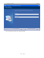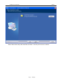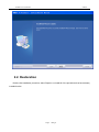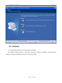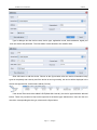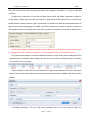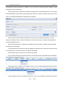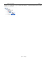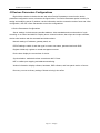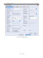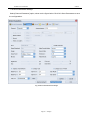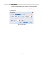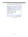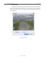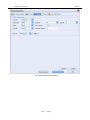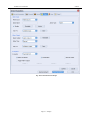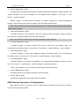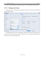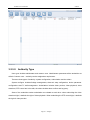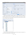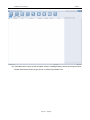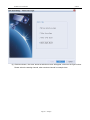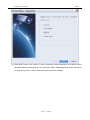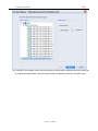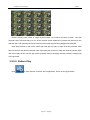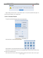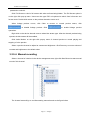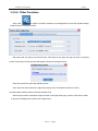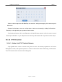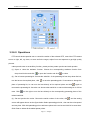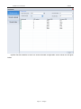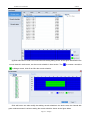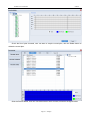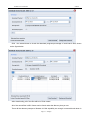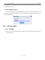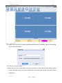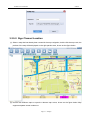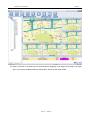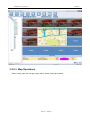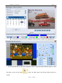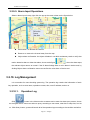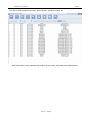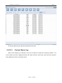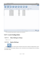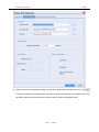
1
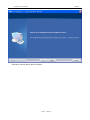
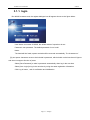
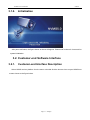
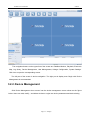
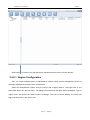
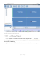
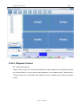
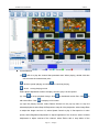
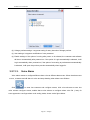
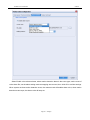
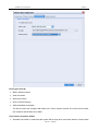
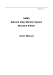
NVMS Network Video Monitor System Standard Edition Users Manual NVM S5.0 Users M anual NVM S Contents Contents ............................................................................................................. 1 1. Introduction ............................................................................................ 2 1.1. Brief Introduction ............................................................................................................. 2 1.2. Definition ........................................................................................................................... 3 1.3. System Features ............................................................................................................. 3 1.4. System operating environment ..................................................................................... 3 2. Installation and Unload ......................................................................... 3 2.1. System Installation .......................................................................................................... 3 2.2. Restoration ....................................................................................................................... 9 2.3. Unload ............................................................................................................................. 10 3. Running and Operation ....................................................................... 11 3.1. Start and Login............................................................................................................... 11 3.1.1.login .......................................................................................................................... 12 3.1.2.Initialization................................................................................................................ 13 3.2. Customer-end Software Interface............................................................................... 13 3.2.1.Customer-end Interface Description........................................................................... 13 3.2.2.Device Management .................................................................................................. 14 3.2.2.1. 3.2.2.2. 3.2.2.3. 3.2.2.4. Region Configuration ................................................................................ 15 Add Device .............................................................................................. 16 Device Diagnos is ...................................................................................... 22 Device Configurations ............................................................................... 22 3.2.3.User Management ..................................................................................................... 41 3.2.3.1. 3.2.3.2. Management Scope ................................................................................... 44 Authority Type ......................................................................................... 45 3.2.4.Linkage Management ................................................................................................ 47 3.2.5.Preview ..................................................................................................................... 53 3.2.5.1. 3.2.5.2. 3.2.5.3. 3.2.5.4. 3.2.5.5. 3.2.5.6. Non Pattern Preview ................................................................................. 53 Pattern Play.............................................................................................. 54 Preview Control........................................................................................ 56 Manual recording...................................................................................... 57 Real time Alarm Information ...................................................................... 58 Other Functions ........................................................................................ 59 3.2.6.PTZ Control ............................................................................................................... 60 3.2.6.1. Enter into PTZ Control Screen.................................................................... 60 Page 1 94Pages NVM S5.0 Users M anual 3.2.6.2. NVM S Operations ............................................................................................... 61 3.2.7.Record schedule........................................................................................................ 62 3.2.8.Record Playback ....................................................................................................... 66 3.2.8.1. 3.2.8.2. 3.2.8.3. 3.2.8.4. 3.2.8.5. 3.2.8.6. 3.2.8.7. Hard disk Recorder Playback ..................................................................... 66 Local Storage Playback ............................................................................. 67 Record Query........................................................................................... 68 Playback Control ...................................................................................... 69 Edit Record File ....................................................................................... 71 Download Record File............................................................................... 71 Playback Snap .......................................................................................... 73 3.2.9.Electronic Map........................................................................................................... 73 3.2.9.1. 3.2.9.2. 3.2.9.3. 3.2.9.4. 3.2.9.5. 3.2.10. Add Map ................................................................................................. 73 Sign Channel Location .............................................................................. 75 Map Operations ........................................................................................ 78 Channel Operations ................................................................................... 79 Alarm Input Operations ............................................................................. 82 Log Management .......................................................................................... 82 3.2.10.1. 3.2.10.2. 3.2.10.3. Operation Log .......................................................................................... 82 History Alarm Log .................................................................................... 84 Current Alarm Log .................................................................................... 85 3.2.11. Local Configuration .............................................................................................. 86 3.2.11.1. 3.2.11.2. 3.2.11.3. 3.2.11.4. Video Settings in Group............................................................................. 86 System Settings ........................................................................................ 86 Voice Alarm ............................................................................................. 88 Display Settings........................................................................................ 91 1. Introduction 1.1. Brief Introduction NVMS 5.0 Standard Edition is provided to small video surveillance network for preview / playback / video and other services. Although every attempt is made to provide accurate information, th is user manual may contain some inaccurate information, or information that is incompatible with product function and operation, or misprint. The contents of this manual will be updated as product features and functions are changed. We will periodically modify and update the products or procedures described in this manual. The updated contents will be added in a new version of the manual without prior notice. Page 2 94Pages NVM S5.0 Users M anual NVM S 1.2. Definition CU Custom Unit Customer end DVR Digital Video Recorder Front-end DVS Digital Video Server Front-end 1.3. System Features Support integrated user management, malfunction management, system maintenance and TOPO navigation. Support fine divisions of user authority (localize the detail of the authority division up to device channel) Support functions of stream media transmitting. Support stream media storage and playback; support monitor playback connection status and relatively status notice. Support electronic map allowing with management in different levels. 1.4. System operating environment Operating System: Microsoft Windows XP sp1 or above CPU: Intel Pentium IV2.4 GHz or above Memory: 1G or above 2. Installation and Unload 2.1. System Installation The system software integrates all capabilities into an installation packet. Double click the installation procedure and follow the pop-up indication picture to install. Page 3 94Pages NVM S5.0 Users M anual NVM S Click Next, see the picture shown as below: Page 4 94Pages NVM S5.0 Users M anual NVM S Accept the terms of agreement, click Next. Page 5 94Pages NVM S5.0 Users M anual NVM S Enter use name and the name of the company,click Next. Page 6 94Pages NVM S5.0 Users M anual NVM S Select folder where setup will install files,click Next . See the picture shown as below: Page 7 94Pages NVM S5.0 Users M anual NVM S Click Finish to complete and exit the installation. Page 8 94Pages NVM S5.0 Users M anual NVM S 2.2. Restoration Double click installation procedure, select Repair to re-install all of the procedures that have already installed before. Page 9 94Pages NVM S5.0 Users M anual NVM S 2.3. Unload To unload NVMS will delete all of the procedure of NVMS. Run NVMS installation packet, or click Start-->procedure-->NVMS--> NVMS5.0-->Uninstall, select Remove in the pop-up dialogue box shown as the picture below: Page 10 94Pages NVM S5.0 Users M anual NVM S Click Next, the dialogue box shown as the picture below will pop up. Click Yes to delete all the procedures and function. Click No to cancel the operation and exit. Click Yes to unload procedure, click No to cancel the operation and exit. When unloading procedures, all the servers will be stopped and delete. Please close CU procedure before unload CU. 3. Running and Operation 3.1. Start and Login Page 11 94Pages NVM S5.0 Users M anual NVM S 3.1.1. login Run NVMS customer-end, the register dialogue box will appear shown as the figure below: User Name: user name of NVMS, the default name of supervisor is root. Password: user password. The default password of root is null. Notes: The head-tail line feeds, spaces and tabs will be removed automatically. The characters of [%] and space characters must not be included in password, which should not be less than six figures and does not support function of paste. Select [Save Password] to write in password automatically when log-in the next time. Select [Auto Login] to log-in the next time by using the same registration information. Click Log-in button , wait for verification and initialization. Page 12 94Pages NVM S5.0 Users M anual 3.1.2. NVM S Initialization After pass verification, the figure shown as above will appear. Please wait for about 2~3 seconds for system initialization. 3.2. Customer-end Software Interface 3.2.1. Customer-end Interface Description Select NVMS monitor platform from the menu or double click the shortcut icon to open NVMS host screen shown as the figure below: Page 13 94Pages NVM S5.0 Users M anual NVM S The navigation buttons on the upper line of the screen are: Realtime Monitor, Playback, Electronic Map, Log Query, Device Management, User Management, Linkage Configuration, System Settings. Click icon to open the corresponding screen. The left part of the screen is device navigation. The right part is display area. Begin with Device Management is recommended. 3.2.2. Device Management Click Device Management icon to enter into the device management screen shown as the figure below. Users can add, modify , and delete devices or region set device parameters and device timing. Page 14 94Pages NVM S5.0 Users M anual NVM S Click button to unfold or conceal the device management tree screen from the left part. 3.2.2.1. Region Configuration User can create multiple levels of administrative regions under central management server for managing administrative regions more convenience. Select the administrative regions that you want to add a region under it. Then right click it, and select Add area in the pop-up menu. The dialogue box shown as the figure below will appear. Type in region name, and specify the region to which it belongs. Click OK to confirm adding. The newly add region will be shown in the device tree. Page 15 94Pages NVM S5.0 Users M anual NVM S Users can modify the existed region by clicking it and then select Edit area on the pop-up menu, type the new name into the pop-up dialogue box, click OK to confirm the modification. Users can delete the existed region by clicking it and then select Delete area on the pop-up menu, click OK to confirm delete on the pop-up screen. The device list will refresh to the current region. The device list displays the devices that are under the current region only. 3.2.2.2. Add Device There are generally two methods to add devices to central management server. The first one is to register to central management server initiatively, which will add the device after receiving the device-end registration information. Another one is to add device manually, which includes adding device according to the device information that has been typed in and adding device selectively according to automatic detection. Please follow the indications below to add device manually accor ding to the device information that has been typed in. Run video monitor platform customer-end, register into NVMS, select the administrative region on the left device tree (device will be added into the selected region or you can modify the device information on the screen shown as the figure below), single right click to select Add Device, the dialogue box shown as the picture below will appear. Page 16 94Pages NVM S5.0 Users M anual NVM S Type in dialogue box the device name, device type, registration mode, device address, signal port and user name and password. The information is also allowed to be modified here. Click OK button to add the device. Shown as the figure below, after the device information being typed in completely and correctly and if the device is running normally, the device will be displayed in the device management list, and its status will be [On line]. If the device that needs to be added is DVR(hard disk recorder), the device type should be selected before. There is a [?] button for help on the right side of the device type selection box. User can click it to check the corresponding device type, shown as the figure below. Page 17 94Pages NVM S5.0 Users M anual NVM S NOTE: the device port for hard disk recorder and video server is the device signal port; default is 5050. User name and password default is Admin, 888888. The other manual method of adding device is to detect device automatically and to add the detected on line device. Click Show online device button on the device adding dialogue box shown as the figure below: The on line device detection dialogue box will appear shown as the figure below: Page 18 94Pages NVM S5.0 Users M anual NVM S List all the devices in the same network according the beginning port and stopping port and set the begging port and stopping port to fix the detection scope. Select the device that needs to be added in the list, and click Select button to exit online device detection screen and return to Add device screen. The device type, device address, and signal port will be acquired automatically, shown as the figure below. Type in device name, user name and password, click OK to add. After the device information being typed in completely and correctly and if the device is running normally, the device will be displayed in the device management list, and its status will be [On line]. Please follow the steps below to add device by registering to central management server initiatively, Page 19 94Pages NVM S5.0 Users M anual NVM S which will add the device after receiving the device-end registration information. It is only for hard disk recorders. Configure the information of hard disk recorder device which will initiate reg istration request to central server. Please make sure that the network of hard disk recorder/ video server is connected to NVMS network normally, and then type in IE browse the IP address of hard disk recorder/video server to open its web screen. After logging in to NVMS, click Device Parameter to type in IP address, register port and register intervals of managing host. Click OK to confirm the operations. Shown as the figure below: NOTE: when register common hard disk recorder/video server to CMS server, users needs to type in management host the initiative registration port: iDVR default is 8004, sDVR default is 8003. Run video monitor platform customer-end(NVMS monitor) to Login. Select Device Management, the registered device information will be displayed in the device list, shown as the figure below. The status of the device now is uncreated. Select the device in the device list, click Add button to pop-up the dialogue box shown as the figure below. Type in device name and user name and password (default Admin, 888888), click OK to confirm addition. If modified information of IP, port, user name, password and so on, users need to modify the Page 20 94Pages NVM S5.0 Users M anual NVM S corresponding device information on NVMS so as to assure the normal connection between central management server and device. Select the device that needs to be modified in the device list, and click Modify button to pop -up the Device Modification screen shown as the figure below. Users can modify IP address, device port, device name, user name and password of the device on the screen. Select the device that needs to be deleted in the device list, and click Delete button to confirm whether to delete the device. Click OK to delete it and the device will be not under the management of central management server. NOTE: the deleted device is allowed to be added again to the system. Follow the steps of [Create New Device] to add it again. The time differences of each device are also displayed in the device list. Select the devices and click the Timing button to synchronize time in accordance with NVMS. Click Refresh button to refresh all of the device information. By right clicking device in the device list, users can also add, modify and delete device parameters. By pressing CTRL or SHIFT key and drag the mouse, users can select multiple devices at one time. By right clicking device in the selected device list, users can add devices, modify the first device Page 21 94Pages NVM S5.0 Users M anual NVM S parameters in the list and delete all the selected devices. The online device supports synchronize operation. Select the device that needs to be synchronized, and click Synchronization button to make the device time accordance with NVMS. 3.2.2.3. Device Diagnosis Click Diagnosis button on the device management screen to make a diagnosis to all the devices, shown as the figure below. Display device status: device connected correctly, device connected incorrectly, and the causes of fault, such as device address unreachable or user name or password mistake. 3.2.2.4. Device Configurations Run video monitor platform customer-end. Select the device that needs to be configured in the device management tree, right click Device Parameters to open device configuration screen. Pay Page 22 94Pages NVM S5.0 Users M anual NVM S attention that this operation is only for those online devices. The device parameter menu of offline devices will be concealed. Page 23 94Pages NVM S5.0 Users M anual NVM S -D Devices Parameters Configurations Right click the device in the device tree and select Device Parameter to enter into the device parameter configuration screen, shown as the figure below. The Device Parameter option is mainly for setting and modifying server IP address, version information and the connection mode of outer net. After configuration, click OK->Save Parameters to save the configurations. Device Parameters Configurations Server settings: include remote controller address, video standards and record method of cycle recording or not when hard disk full. Display server channel numbers, alarm input and output numbers, device serial number and the accessed hard disk numbers. Network settings: IP address, gateway mask, etc. PPPoE settings: enable it, and then type in correct user name, password and main DNS. Register initiatively: register to central management server. Device time: display the current time of device. Synchronization: make device time accordance with PC time. NAT: to realize port mapping and address transferring. Version information: display software, hardware, DSP software, and front panel version of server. Recovery: recover to factory settings. Restart to bring it into effect. Page 24 94Pages NVM S5.0 Users M anual NVM S Fig. Device Parameters Settings Page 25 94Pages NVM S5.0 Users M anual NVM S Channel Parameters Settings Select [Channel Parameter] option, shown as the figure below. Click OK->Save Parameters to save the configurations. Fig. Channel Parameters Settings Page 26 94Pages NVM S5.0 Users M anual NVM S Enable Record It is mainly for record schedules setting of timing record, outer alarm, motion detection and motion detection/outer alarm. Each record type supports two time schedules. Click Set button after enable record to enter into the following screen shown as the figure below. Fig. Record Plan Settings Page 27 94Pages NVM S5.0 Users M anual NVM S Record pre-record and time delay are valid only for motion detection and outer alarm record. Motion Detection Click Set button after motion detection to enter into the setting screen shown as figure below. Select Set Area frame, left click mouse to select area, and right click to cancel selection. Click OK to save selection, and click Display Area to show the selected area. The sensitivity is divided into six levels. Fig. Motion Detection Settings Page 28 94Pages NVM S5.0 Users M anual NVM S Click Linkage Mode after motion detection to enter into the linkage setting screen shown as the figure below. It supports triggering channel record, linkage monitor alarm, audio alarm, upload to center and trigger alarm output. Fig. Linkage Mode Settings Page 29 94Pages NVM S5.0 Users M anual NVM S Mosaic Settings Click Set button after Mosaic to enter into the setting screen shown as the figure below. Select Set Area frame, left click mouse and drag to select area. It supports two areas of video shield. Click OK to save area mosaic setting, click Display Area to show the selected area. Fig. Mosaic Settings Page 30 94Pages NVM S5.0 Users M anual NVM S Video Signal Lost Alarm Settings Click Set button after video signal lost alarm to enter into the setting screen shown as the figure below. By selecting trigger modes and the relevant channels to make the channel do corresponding triggers include monitor alarm, voice alarm, upload to center and trigger alarm output. Fig. Video Lost Alarm Settings Page 31 94Pages NVM S5.0 Users M anual NVM S Type: main bit stream, sub bit stream. Please enable sub bit stream frame before setting sub bit stream parameters. Video standards: PAL and NTSC is displayed only without being set. Image quality: best, better, high, common, lower, and lowest, which are allowed to be set under variety bit rate only. Bit stream type: set video stream and compound stream mode. Bit rate type: Constant bit rate, variety bit rate and limited bit rate. Bit stream format: common H.264, enhanced H.264. Video frame rate: includes FULL, 1, 2, 4, 6, 8, 10, 12, 16, and 20. Coding format: includes CIF, D1, and SD. Video bit rate: from 16K to self-defined. It can be set under constant bit rate and limited bit rate only. Color settings: brightness: from 0---128; contrast: from 0---64; Saturation: from 0---64; hue: from 0---128. OSD settings: display OSD time and channel name. Console parameters configurations Select Console Parameter shown as the figure below. Click OK-> Save Parameters to save settings. Page 32 94Pages NVM S5.0 Users M anual NVM S Fig. Cons ole Parameters Settings Page 33 94Pages NVM S5.0 Users M anual NVM S Channel number: display the current selected channel. Baud rate: data quantity transmitted per second; there are four baud rates for selecting: 1200, 2400, 4800, and 9600. Data size: data size in communicating with PTZ, there are five data sizes for selecting: 4, 5, 6, 7, 8. 8 is recommended. Stop size: stop size in communicating with PTZ. There are three sizes for selecting: 1, 1.5, 2. 1 is recommended. Parity: none, odd and even. None is recommended. Stream control: there are three modes: none stream control, hard stream control and soft stream control. None stream control is recommended. Decode type: set the PTZ protocol. It is recommended to make device protocol accordance with PTZ. Decoder address: from 0 to 100; the decoder address should be accordance with PTZ address. Alarm Parameters Configurations Select Alarm Parameters to enter into the setting screen shown as the figure below. Click OK -> Save Parameters to save the settings. Page 34 94Pages NVM S5.0 Users M anual NVM S Fig. Alarm Paramet ers Settings Page 35 94Pages NVM S5.0 Users M anual NVM S Alarm input: Alarm input numbers: It supports 8 alarm inputs. Alarm types: It includes normally open and normally closed. Process: Select Process frame and click Linkage Mode to enter into the screen shown as the figure below. Users can set alarm trigger channel recording, linkage monitor alarm, voice alarm, upload to center and trigger alarm output. PTZ linkage: Set PTZ linkage when alarm input occurs to make PTZ of the channel enable preset, pattern and track as the method set before. Fig. Alarm Linkage Settings Alarm output: Alarm output NO.: Up to 4 outputs can be set. Output time delay: Time delay of triggering alarm output including 5 seconds, 10 seconds, 30 seconds, 1 minutes, 2 minutes, 5 minutes, and 10 minutes. Exception settings: trigger monitor alarm, voice alarm, upload to center, and trigger alarm output by hard disk full, IP conflict, illegal access, hard disk Page 36 94Pages NVM S5.0 Users M anual NVM S error and input signal lost. (The hard disk recorder supports exception of hard disk full only.) Customer management configurations Select Customer Management to enter into the setting screen shown as the figure below. Users can modify user password. Super user can add new users to system and give newly added users local authority and remote authority. Click Authority and then select authorization frame, click OK to give the authority. Click OK->Save Parameters to save settings. Fig. Customer Management Settings Device Status Select Device Status to enter into the setting screen shown as the figure below. It will display hard disk status which includes hard disk capacity; hard disk remained capacity and whether hard disk is Page 37 94Pages NVM S5.0 Users M anual NVM S allowed to be wrote in or not. It will also display channel status which includes record status, signal status, main bit stream bit rate, whether to enable sub bit stream and the sub bit stream bit rate when enabled. Users can select the frame of automatic acquire status to acquire device status every 5 seconds automatically. Fig. Device Status 5X Devices Parameters Configurations Right click the device in the device tree, and select Device Parameter s to enter into device parameters setting screen which includes six options shown as the figure below. Page 38 94Pages NVM S5.0 Users M anual NVM S <Device Parameters> option It includes server configuration information, network configuration information, initiative register, and version information. All of the information can be displayed and modified in the screen of <tool column>--<system settings>. Initiative register: for setting device information of initiative registering to central management software, which includes content server address, port and register time intervals. Note: if the current mode is acquiring IP dynamically, the IP address will be assigned automatically without being changed. <Channel Parameters> option It includes settings of motion detection, video lost, channel overlay information, image bit stream and frame rate, image parameters and record time schedule. Note: users can set a channel only, and copy its settings to other channels. <Console Parameters> option It includes settings of channel camera PTZ protocol, baud rate, and address code. The corresponding information screen on device end: <Tool column>--<system settings>--<video settings>. <Alarm Parameters> option It includes settings of alarm input triggering setting and linkage setting. The corresponding information screen on device end: <Tool column>--<system settings>--<alarm settings>. <User Management> option It includes settings of user rights and password. The corresponding information screen on device end: <Tool column>--<system menu>--<system settings>--<advanced settings>. If user Login as Admin, user can modify user authority and password directly. <Device Management> option It includes remote device upgrade and device synchronization. <Device Status> option It includes hard disk status and channel status information. 8X9X Devices Parameters Configurations Right click the device in the device tree and select Device Parameters to enter into the setting screen shown as the figure below. Page 39 94Pages NVM S5.0 Users M anual NVM S Users can set system parameters, camera parameters, alarm parameters, record parameters, and device management and device information acquire to 8x9x devices. Note: 8X9X web end device parameter settings is similar with device local settings, some of the differences are shown as the table below. Table IE end newly added settings Route <device parameters>-><system Contents Device name is self-definable, which can be refreshed to device end. settings>-><device parameters> <device parameters>-><system Synchronization can make device time accordance with PC time. settings>-><device parameters> <device parameters>-><camera Channel name is self-definable, which can be refreshed to device end. settings>-><image settings> Page 40 94Pages NVM S5.0 Users M anual <device parameters>-><alarm NVM S Alarm name is self-definable, which can be refreshed to device end. settings>-><alarm input> Alarm output name is self-definable, which can be refreshed to device <device parameters>-><alarm end. settings>-><alarm output> 3.2.3. User Management User configuration is a part of the security management. Except setting user name and password, users also have to configure its authority. One customer can possess one or more authorities. What is more, users is also related to the area they locates, which means user s created under a certain area possess the authority of managing the devices under the same area only. Enable video monitor platform customer-end and Login to user management screen, shown as the figure below. Page 41 94Pages NVM S5.0 Users M anual NVM S Click Add button to set the relevant customer information such as user type, area located in, authority of user, and so on, shown as the figure blow. Click OK to save settings. The column with must be typed in contents. Page 42 94Pages NVM S5.0 Users M anual NVM S Users can check the newly add user after adding it in the user list. Select a user to check all its information and authority in details, shown as the figure below. Page 43 94Pages NVM S5.0 Users M anual NVM S Select a user and click Modify to modify the information of users. Click Delete to delete the user. 3.2.3.1. Management Scope Management scope is corresponding to the area that user locates in. it is valid only for the local area, shown as the figure below. After setting the area of user such as management center/DVR, user will not check the devices of other areas or users information after re-Login.If re-Login,user can only see and management the local devices and users, shown as the figure below. Page 44 94Pages NVM S5.0 Users M anual NVM S 3.2.3.2. Authority Type User types include administrator and common user. Administrator possesses all the authorities as default. Common user authority can be assigned as requirement. There are three types of authority: system configuration, authorization and the others. System configure includes linkage management, electronic map configuration, device parameter configurations and TV wall management. Authorization includes video preview, v ideo playback, video download, PTZ control and voice talk; the others include alarm confirm and log query. Some of the authorities under authorization are related to each other: when authorizing the video download right, it defaults the right of video playback. When authorizing the PTZ control right, it defaults the right of video preview. Page 45 94Pages NVM S5.0 Users M anual NVM S Among the device parameter configuration authority of system settings and the authorities of authorization (includes video preview, video playback, video download, PTZ control and voice talk), users can configure the device and its channels in the local area, which means the authority can clarify to device or channels, shown as the figure below. Users can only have the right to operate the functions that have already been authorized. The functions without being permitted are in forbidden status. Page 46 94Pages NVM S5.0 Users M anual NVM S 3.2.4. Linkage Management Event linkage means to operate a serial of actions when appointed alarm event occurs through configurations, so as to reduce the maintenance day-to-day workload and to enhance the capacity to respond to alarm event. This function mainly includes event linkage configuration definition and linkage action configuration definition. Linkage actions include: linkage preview, linkage alarm output, linkage PTZ control , linkage record, linkage TV wall. Linkage preview it is triggered by motion detection, IO alarm, and signal lost. It will be played on the appointed channels in group video display areas of video monitor platform customer -end. Linkage PTZ control it is triggered by motion detection, IO alarm, and signal lost. The appointed channel will control PTZ to enable preset, pattern and track. Linkage PTZ control includes turn to preset, start track, and start pattern. When linkage PTZ control is selected, the concrete PTZ actions is needed to be configured; when turn to preset, start track and stop track is selected, the PTZ action serial NO or the track NO is needed to be typed in (preset number supports 1 to 16, track number is decided by the numbers that concrete PTZ protocol supports, it is usually 1). Linkage alarm output it is triggered by motion detection, IO alarm, and signal lost. The appointed alarm output port will process alarm. Users can set timing length to define time of linkage alarm output. Linkage record it is triggered by motion detection, IO alarm, and signal lost. The appointed channel will play record on the stream media integrated storage server NRU. Take operations of adding IO alarm linkage record for example: (1) Open video monitor platform customer-end, switch to linkage management screen, shown as the figure below: Page 47 94Pages NVM S5.0 Users M anual NVM S (2) Click Add button to pop up the navigation screen of adding linkage, shown as the figure below. Please select alarm resource type at first; it is alarm input alarm here. Page 48 94Pages NVM S5.0 Users M anual NVM S (3) Click Next button, the event resource selection screen will appear, shown as the figure below. Please select the starting channel, take a random channel for example here. Page 49 94Pages NVM S5.0 Users M anual NVM S (4) Click Next button, the linkage action selection screen will appear, shown as the figure below. Please select the actions after alarm occurs, take record for example here, Page 50 94Pages NVM S5.0 Users M anual NVM S (5) Click NEXT button, the screen of action processing channel selection and linkage action parameter selection will appear, shown as the figure below. Please appoint channels and time to act when alarm occurs. Take 4 channels and 20 seconds for example. Page 51 94Pages NVM S5.0 Users M anual NVM S (6) Click NEXT, the linkage confirm screen will appear. Please type in linkage name and confirm all the selections made before, and then select Enable Immediately, shown as the figure below. Page 52 94Pages NVM S5.0 Users M anual NVM S (7) Click Create, it will prompt creation success. Select a linkage in the linkage list, the detail linkage information can be checked on the right side, shown as the figure below. When NVMS receives alarm event it will linkage the actions. (8) Select a linkage; click Delete to delete relevant linkage information. If the linkage relevant channel is deleted, the relevant linkage information will be deleted. 3.2.5. Preview 3.2.5.1. Non Pattern Preview Double click device name in the left device tree to open its entire channels preview on the right preview screen, shown as the figure blow. Page 53 94Pages NVM S5.0 Users M anual NVM S Double clicking group name or single channel name can achieve the same function. Left click channel name, hold and drag it to one of the preview screen windows to preview the channel on the relevant split. The opened previews in the preview windows support being dragged and adjusted. Click Stop Preview on the device name right click pop-up menu to stop all of the previews. Click Stop Preview on the relevant channel name right click pop-up menu to stop the channel preview. Right click on the play screen can also pop up the operation menu of stopping channel preview or stopping all of the previews. 3.2.5.2. Pattern Play Click to open monitor customer-end configuration, shown as the figure below. Page 54 94Pages NVM S5.0 Users M anual NVM S Right click the Create Video Group button on the right area to rename the group. Select the device/channel that required in the left device list, and click to enter into the video group (each video group supports up to 16 channels), or users can also use left key of mouse to add videos by dragging the device of management center or channel of the device. Click to select video group and create multiple video groups. The scope of pattern time is from 20S to 7200S, nor it will pop up the fo llowing prompt: Page 55 94Pages NVM S5.0 Users M anual NVM S Single clicking the Start Pattern or Stop Pattern button in the preview operation label page can control the preview pattern of the created group. 3.2.5.3. Preview Control The preview operation label page is shown as the figure below. Click Start Pattern to start preview group pattern; Click Slit Switch to set preview separate screen mode. Click Stop the Current Preview to stop the current playing image; click Stop All the Previews to stop the entire current playing preview. Click Screen lock to lock the video monitor platform customer-end monitor. Users need to type in Page 56 94Pages NVM S5.0 Users M anual NVM S password to unlock it. Click Full Screen to view in full screen with other tool bars being hidden. The Full Screen option is on the right click pop-up menu. Users can also type ESC on keyboard to switch from full screen and former mode. Double click mouse on the preview channel to zoom out it. When linkage preview occurs, click Clear to recover to normal preview status; click to disable linkage preview. Click to enable linkage preview operations. Right click on the device channel name to select bite stream type. After the channel preview being opened, the bite stream will be enabled, Click Audio Monitor on the right click pop-up menu of channel preview to control playing and stopping of voice preview. Select a preview channel to adjust its contrast and brightness. Click Recovery to recover values of contrast and brightness to the default value. 3.2.5.4. Manual recording Select a channel of a device in the device management tree, right click Start Record to start manual record of this channel. The channel name will go to red after starting manual record as the figure below. Page 57 94Pages NVM S5.0 Users M anual NVM S Select a channel of a device in the device management tree, right click Stop Record to stop manual record of this channel. 3.2.5.5. Real time Alarm Information The lower part of the preview display area is real time alarm area which displays the latest alarm information one by one, the alarm information includes alarm time, alarm resource, alarm level, alarm type and alarm status. Right click mouse and select Delete to delete the alarm information. It is shown as the figure below. Page 58 94Pages NVM S5.0 Users M anual NVM S 3.2.5.6. Other Functions Snap: click to switch to monitor customer-end configuration to enter into System Setting screen shown as the figure below. Set snap route and return to preview screen, click Snap on the right click pop -up menu of preview screen, the prompt of snap success will appear, shown as the figure below. Click the route link to open the relevant picture. Voice talk: click Voice talk on the right click pop-up menu of the device name to control communication between device end and customer end. Alarm output control: click Alarm Output Control on the right click pop-up menu of the device name to pop up the dialogue box shown as the figure blow. Page 59 94Pages NVM S5.0 Users M anual NVM S Select an alarm output and click Start/Stop to control the starting and stopping of the alarm output in device end. Remote Confirm Alarm: users can confirm alarm in device-end remotely by clicking Confirm Alarm Remotely on the right click pop-up menu of device name. One key layout/retreat: click Layout/Retreat on the right click pop-up menu of device name to control alarm input information. Layout will process for alarm input and retreat will not process for alarm input. 3.2.6. PTZ Control 3.2.6.1. Enter into PTZ Control Screen Open [NVMS-video monitor customer-end], select a device that already registered in the Device Management center, then open the preview of a device channel and select PTZ Setting in TAB screen. The PTZ control screen shown as below will appear. Page 60 94Pages NVM S5.0 Users M anual NVM S 3.2.6.2. Operations PTZ control window permits user to control the motion of the selected PTZ, control the PTZ camera to turn to right, left, up, down, to zoom out/in the target, adjust focus and aperture to get high quality pictures. It also permits user to set auxiliary function, preset preview, pattern preview and track preview. (1) Open or close the assistant function. Choose the corresponding assistant function from drop-down list box and click to open the function and click to close. (2) Set or browse presetting bit. Choose the serial No. of the presetting bit from drop-down list box, turn the lens to the required place, click to save the presetting point. If user wants to change the place of presetting bit, he can turn the lens directly to his required place and click again to renovate the presetting bit. Use also can choose other serial No. to set and the setting No. is 256 at most. Click on the right to turn the lens directly to the corresponding presetting place of the related serial No. (3) Set and preview the cruise. Choose the serial number of the cruise, click , and the setting screen will appear shown as the figure below. Select presetting point No., then set the cruise speed and stay time. Click Add presetting point to add more points to the cru ise and click OK to save them. Click Clear to delete all the added preset points. Page 61 94Pages NVM S5.0 Users M anual NVM S Select the cruise serial No in the drop-down list of pattern, click click to stop pattern. (4) Set and preview the track. Choose the track number; click PTZ camera lens to set the running track. Then click click to start pattern preview and to open the track, click to set track memory, run the again to close the memory setting and to close. 3.2.7. Record schedule (1)Open [NVMS-video monitor customer-end], (2)Click enter into record configuration screen shown as the figure below. User can set the video disks, the reserved space, whether circular storage, pre-recorded and delay time, click the Save to take settings effect. Page 62 94Pages NVM S5.0 Users M anual NVM S (3)Click Record schedule to enter into record schedule configuration screen shown as the figure below. Page 63 94Pages NVM S5.0 Users M anual NVM S (4)Click edit button to enter into record schedule setting dialog shown as the figure below.Select the record channel in device tree, set the record schedule in time section. The is common record,the is linkage record, click Ok to effect the record schedule. Click edit button can also modify the existing record schedule.In the device tree, the channel with green markers means it has been setting the record schedule. shown as the figure below. Page 64 94Pages NVM S5.0 Users M anual NVM S Check the list of plan channels, user can start or stop the record plan, click the Delete button to delete the record plan. Click the Record status, user can view video state of each channel, shown as the figure below. Page 65 94Pages NVM S5.0 Users M anual NVM S 3.2.8. Record Playback 3.2.8.1. Hard disk Recorder Playback (1) Enter into video monitor platform customer-end. (2) click to enter into playback screen shown as the figure below. Page 66 94Pages NVM S5.0 Users M anual NVM S (3) select Front Record to enter into the hard disk recorder playback. The data that has been searched are the record data in device end. 3.2.8.2. Local Storage Playback (1) it is similar with the operation of hard disk recorder playback. Switch after entering playback screen to enter into Local record playback. The data that has been searched are the record data in local storage. (2) select the channel of DVR on the left device tree, users can select relevant device to operate. Page 67 94Pages NVM S5.0 Users M anual NVM S 3.2.8.3. Record Query Select the device on the left device tree that to be played back (up to 4 channels can be selected at once), and then select record type on the video search panel, select date on calendar, click Search to start query on hard disk recorder or Local PC. The query result will be displayed on the panel. The time axis will display channels that have record, the channels that does not have record will be displayed later, shown as the figure below. Page 68 94Pages NVM S5.0 Users M anual NVM S Users can select the result to display record type or not to display relevant record type. 3.2.8.4. Playback Control Video playback area Select record to play. The record being searched out will be played on the playback area with the channel name of current device being displayed on the window banner. Double click a channel to zoom out it and double click it again to return to 4 splits mode, shown as the figure below. Page 69 94Pages NVM S5.0 Users M anual NVM S Control Buttons (1) : click it to play the channel that posesses data. When playing, double click time axis to locate the material time point. : click it to pause playing, and click : click it to continue playing; to stop playing record. Select Speed adjustment scale to fast play record or play it in slow speed. (2) click to snap playback image; click edit record files. Click to download record files; click to to display in full screen. (3) right the playing channel, select Delete Channel on the pop -up menu to stop the selected playback, select Stop All Playbacks to stop all of the playbacks, select Image Rate to adjust the image rate into 4:3, select Speed Control to play in fast speed or in slow speed, select Brightness Adjustment to adjust brightness of the channel, select Contrast Adjustment to adjust contrast of the channel, select Edit to edit or stop edition of the Page 70 94Pages NVM S5.0 Users M anual NVM S channel, select Full Screen to display in full screen, select Open Audio to open o close audio of the channel. Time axis operations (1) The scale of time axis is 0 to 24. (2) Rest mouse on time axis, the big time will display all of the material times that the mouse has currently. (3) Roll mouse on time axis to zoom out and in the time axis. (4) The three record types under the time axis are for records selection. (5) Click to turn time axis to the next left page; click left step; click to move time axis to the next to move time axis to the next right step; click to turn time axis to the next right page. 3.2.8.5. Edit Record File Right click the channel that needs to be edited, and select Edit or the button to start editing the relevant channel. Right click the channel that needs to be edited, and select Edit again or the button to stop editing the relevant channel. The relevant MP4 files can be checked under the device edition directory. 3.2.8.6. Download Record File It is for downloading the channels that have been searched out according to time. The download directory can be located. It supports background download with the downloading screen being hidden and the other operations of playback operating simultaneously. When downloading, the download time remained and the current download speed is displayed on the screen. The download progress percentage is displayed on the right upper corner of the screen, shown as the figure below. Page 71 94Pages NVM S5.0 Users M anual NVM S Click + the extend button to check the download progress percentage of each branch files, shown as the figure below. After downloading, all of the files will be in Finish status. All of the record files in MP4 format can be found under the directory that you set. There will be relevant prompts to illustrate it if disk capability not enough or network break down in Page 72 94Pages NVM S5.0 Users M anual NVM S playing back record. If click Stop in the process of downloading, the files that has already been downloaded will be saved. 3.2.8.7. Playback Snap It is for image snapping of the current playing back channel that has been acquired focus. The prompt box will appear after snapping successful. By clicking the link on the prompt screen, users can open the relevant picture. 3.2.9. Electronic Map 3.2.9.1. Add Map (1) Open the video monitor platform customer-end and Login, switch to Electronic Map screen shown as the figure below. Page 73 94Pages NVM S5.0 Users M anual NVM S (2) Select a node in the map navigation, take Management Center for example, right click Create Map, shown as the figure below. (3) Click OK to confirm creation. (4) Right click the map, select Modify on the pop-up menu to modify the map that already added, shown as the figure below. It supports modification of map name and map file. Click OK to confirm modification. Page 74 94Pages NVM S5.0 Users M anual NVM S 3.2.9.2. Sign Channel Location (1) Select a map that has already been created in the map navigation, double click the map node, the preview of the map will be displayed on the right preview area, shown as the figure below. (2) Double click different maps to open the relevant map scene, shown as the figure below. Map supports separate screen modes too. Page 75 94Pages NVM S5.0 Users M anual NVM S (3) Select a channel or a alarm input on the left device navigation, and drag it to the map in the right side, it can layout multiple channel or alarm input, shown as the figure below. Page 76 94Pages NVM S5.0 Users M anual NVM S (4) The channel that has been laid to map can also be previewed in windows by dragging it to the preview window. Multiple channels being previewed simultaneously is supported, shown as the figure below. Page 77 94Pages NVM S5.0 Users M anual NVM S 3.2.9.3. Map Operations Select a map; right click it to pop up the menu, shown as the figure below. Page 78 94Pages NVM S5.0 Users M anual NVM S Right click pop-up menu description: Remove All: to remove all of the channels and alarm inputs in the map. Select Mode: to select a map. Zoom out: to zoom out map. Zoom in: to zoom in map. Pan: to move the whole map. Focus out: to zoom out an area around a certain center point. Full Map Display: to display map in full screen. Close Map: to close the map preview. The above operations can be done by click the following relevant buttons. 3.2.9.4. Channel Operations Select a channel in map; right click it to pop up the menu shown as the figure below. Page 79 94Pages NVM S5.0 Users M anual NVM S Channel preview: to preview the current channel, shown as the figure below. Edit location: to relocate the channel. Remove: to remove the channel away from the map. Channel playback: to search and playback remotely, shown as the figure below. Page 80 94Pages NVM S5.0 Users M anual NVM S PTZ control: to control PTZ by clicking the relevant buttons, shown as the figure below The channel will alarm in red blink exclamatory mark to notify that motion detection alarm or video lost alarm, shown as the figure ; when the alarm stops, the relevant channel returns to normal. Page 81 94Pages NVM S5.0 Users M anual NVM S 3.2.9.5. Alarm Input Operations Select a alarm input in map, right click it to pop up the menu shown as the figure below. Edit location: to relocate the channel. Remove: to remove the channel away from the map. Object alarm confirmation: the object will alarm in red blink exclamatory mark to notify that motion detection alarm or video lost alarm, shown as the figure ; when the alarm stops, the relevant object returns to normal. If the IO alarm linkage links to voice alarm in device end, by clicking Object alarm confirmation users can confirm the voice alarm of device end. 3.2.10. Log Management It is convenient for users checking system log. The operation log contains the information of each key operation, such as user name, operation content, time, user IP address, and so on. 3.2.10.1. Click Operation Log button in the video monitor customer-end to enter into date query screen, shown as the figure below. Users can select to query according to user name, start time or stop time, an d so on. Click Query button, system will search all of the operation logs according to the condition set before. Page 82 94Pages NVM S5.0 Users M anual NVM S The search result includes user name, device IP, time, operation content, etc. Click Save button to save operation information as htm format, and shown as the figure below. Page 83 94Pages NVM S5.0 Users M anual 3.2.10.2. NVM S History Alarm Log When select history alarm log, users can search in condition of alarm type, start time or stop time. Click Query button to search out all of the operation information including alarm resource, alarm type, start time and stop time, shown as the figure below. Page 84 94Pages NVM S5.0 Users M anual NVM S The history alarm log can also be saved as htm forma file. 3.2.10.3. Current Alarm Log When current alarm log is selected, users can not search by setting the searching condition. The current alarm log will be displayed directly with alarm resource, alarm type, start time and stop time being displayed, shown as the figure below. Page 85 94Pages NVM S5.0 Users M anual NVM S The current alarm log can also be saved as htm format file. 3.2.11. Local Configuration 3.2.11.1. Video Settings in Group Refer to 3.2.5.2 3.2.11.2. System Settings Click in the video monitor customer-end to enter into customer configure screen, shown as the figure below. Click System Settings to set it, it includes save route, linkage preview, user settings, and enable settings. Page 86 94Pages NVM S5.0 Users M anual NVM S (1) Setting of save route supports setting of snap route, download route and edit route. Click to open the window of browsing folder. By select a route and confirm it in the window, the route set will be displayed on the file frame under the route, shown as the figure below. Page 87 94Pages NVM S5.0 Users M anual NVM S (2) Linkage preview settings. It supports setting of rotary intervals of linkage preview. (3) User settings. It supports modification of user password. (4) Enable settings. If the option of running after power on is selected, the customer -end software will be run automatically after powered on. If the option of Login automatically is selected, it will Login automatically when powered on; if the option of recovering to preview status automatically is selected, it will open the previous preview automatically when logged in. 3.2.11.3. Voice Alarm Voice alarm means to configure different alarm voice to different alarm event. When the alarm event occurs, customer-end will alarm in voice and stop alarming when alarm event finishes. Click to enter into customer end configure screen, click voice scheme to enter into voice scheme configure screen; enable alarm voice scheme to configure alarm voice file ( *.wav) for event type and to confiugre alarm vocie ending mode, shown as the figure below. Page 88 94Pages NVM S5.0 Users M anual NVM S Select Enable voice alarm scheme, select motion detection alarm in the event type, set the route of voice alarm file, set the alarm ending mode as stopping at event end, then click OK to confirm settings. When system receives motion detection event, the customer-end will enable alarm voice; when motion detection event stops, the alarm voice will stop too. Page 89 94Pages NVM S5.0 Users M anual NVM S Event types include : Motion detection alarm Video lost alarm Alarm input alarm Device on/off line alarm Video download accomplish The above events can configure with alarm voice. When system receives one of the above events, the customer end will start voice alarm. Voice alarm conclusion modes: Automatic conclusion: it means that the system will not play other voice alarm after the current alarm Page 90 94Pages NVM S5.0 Users M anual NVM S event ends. Event finish conclusion: it means that the voice alarm will stop when the alarm event finishes. Delay conclusion: it means that the voice alarm will play with lasting the delay time that set in delay time. For example, the time delay is set as 30s, the voice alarm will be played 30s and then stops without concerning the time length of the alarm event. Users can select the conclusion mode as they need. The event type of device on/off line and video download accomplish supports only one mode of conclusion, the Automatic Conclusion. When unselect voice alarm, the voice alarm function will be disabled. No matter which kinds of event type occurs, there will be none voice alarm playing. 3.2.11.4. Display Settings The device with double graphic cards supports two monitor accessing. Users can configure monitor as real time preview on monitor 1 , history playback or electronic map on monitor 2, so that users can operate real time preview and history playback or operate real time preview and electronic map at the same time. Modify the display configuration as double screen display mode, shown as the figure below. Page 91 94Pages NVM S5.0 Users M anual Click NVM S to enter into customer end configuration screen, click display settings, real time preview is default on monitor 1, set electronic map on monitor 2. Click OK, the real time preview and electronic map will be displayed at the same time, shown as the figure below. Page 92 94Pages NVM S5.0 Users M anual NVM S Configure history playback on monitor 2, real time preview and history playback will be displayed at the same time. Page 93 94Pages