1
ECLIPSE MATRIX INSTALLATION
Instruction Manual
Eclipse Matrix Installation Instruction Manual
© 2007, 2009 Vitec Group Communications. All rights reserved.
Part Number 810298Z Rev. 7
Vitec Group Communications LLC
850 Marina Village Parkway
Alameda, CA 94501
U.S.A.
Vitec Group Communications Ltd
7400 Beach Drive
IQ Cambridge
Cambrideshire
United Kingdom
CB25 9TP
The Vitec Group plc
Beijing Representative Office
Room 706, Tower B
Derun Building, YongAn Dongli A No.3
Jianwai Ave., Chaoyang District
Beijing, P.R.China 100022
Clear-Com is a registered trademark of Vitec Group Communications.
The Clear-Com logo is a registered trademark of Vitec Group Communications.
Eclipse is a registered trademark of Vitec Group Communications.
Website: www.clearcom.com
CONTENTS
INSTALLATION OVERVIEW . . . . . . . . . . . . . . . . . . 1-1
Introduction . . . . . . . . . . . . . . . . . . . . . . . . . . . . . . . . . . . . . . . 1-1
Step-by-Step Installation . . . . . . . . . . . . . . . . . . . . . . . . . . . . . 1-3
Verify the Shipment. . . . . . . . . . . . . . . . . . . . . . . . . . . . . . . . . . . 1-3
Select Locations for the Components . . . . . . . . . . . . . . . . . . . . . 1-3
Determine the Wiring Requirements . . . . . . . . . . . . . . . . . . . . . . 1-3
Install Components in Rack . . . . . . . . . . . . . . . . . . . . . . . . . . . . . 1-4
Install Cables . . . . . . . . . . . . . . . . . . . . . . . . . . . . . . . . . . . . . . . . 1-4
Connect Cables and Auxiliary Wiring . . . . . . . . . . . . . . . . . . . . . . 1-4
Connect to Mains AC Power . . . . . . . . . . . . . . . . . . . . . . . . . . . . 1-5
Matrices . . . . . . . . . . . . . . . . . . . . . . . . . . . . . . . . . . . . . . . . . . . 1-5
Panels . . . . . . . . . . . . . . . . . . . . . . . . . . . . . . . . . . . . . . . . . . . . 1-6
V-Series Panels . . . . . . . . . . . . . . . . . . . . . . . . . . . . . . . . . . 1-6
4000 Series II Panels . . . . . . . . . . . . . . . . . . . . . . . . . . . . . . 1-6
ICS Panels and i-Stations . . . . . . . . . . . . . . . . . . . . . . . . . . . 1-6
Configure the System . . . . . . . . . . . . . . . . . . . . . . . . . . . . . . . . . . 1-6
Verify the Operation of the System . . . . . . . . . . . . . . . . . . . . . . . 1-6
Matrix Indicators to Verify . . . . . . . . . . . . . . . . . . . . . . . . . . . . . 1-7
Eclipse Omega . . . . . . . . . . . . . . . . . . . . . . . . . . . . . . . . . . . 1-7
Eclipse Median . . . . . . . . . . . . . . . . . . . . . . . . . . . . . . . . . . . 1-7
Eclipse Pico . . . . . . . . . . . . . . . . . . . . . . . . . . . . . . . . . . . . . . 1-7
Eclipse-32 . . . . . . . . . . . . . . . . . . . . . . . . . . . . . . . . . . . . . . . 1-8
PLACING SYSTEM COMPONENTS. . . . . . . . . . . . 2-1
Component Location Requirements . . . . . . . . . . . . . . . . . . . . 2-1
Eclipse Matrices . . . . . . . . . . . . . . . . . . . . . . . . . . . . . . . . . . . . . . 2-1
Eclipse Omega Matrix . . . . . . . . . . . . . . . . . . . . . . . . . . . . . . . . 2-1
Eclipse Median Matrix . . . . . . . . . . . . . . . . . . . . . . . . . . . . . . . . 2-2
Eclipse Pico Matrix . . . . . . . . . . . . . . . . . . . . . . . . . . . . . . . . . . 2-2
Eclipse-32 Matrix . . . . . . . . . . . . . . . . . . . . . . . . . . . . . . . . . . . . 2-3
Interface Frame(s) and Power Supplies . . . . . . . . . . . . . . . . . . . . 2-3
IMF-3 Interface Module Frame . . . . . . . . . . . . . . . . . . . . . . . . . 2-3
IMF-102 Interface Module Frame . . . . . . . . . . . . . . . . . . . . . . . 2-4
DIF-102 Interface Module Frame. . . . . . . . . . . . . . . . . . . . . . . . 2-5
Intercom Panels and Expansion Panels . . . . . . . . . . . . . . . . . . . . 2-5
External Computer . . . . . . . . . . . . . . . . . . . . . . . . . . . . . . . . . . . . 2-5
POWERING SYSTEM COMPONENTS . . . . . . . . . 3-1
Power Requirements . . . . . . . . . . . . . . . . . . . . . . . . . . . . . . . 3-1
Matrices. . . . . . . . . . . . . . . . . . . . . . . . . . . . . . . . . . . . . . . . . . . . . 3-1
Clear-Com Communication Systems
Eclipse Matrix Installation Instruction Manual
i
Eclipse Omega Matrix . . . . . . . . . . . . . . . . . . . . . . . . . . . . . . . . 3-1
Eclipse Median Matrix . . . . . . . . . . . . . . . . . . . . . . . . . . . . . . . . 3-2
Eclipse Pico Matrix . . . . . . . . . . . . . . . . . . . . . . . . . . . . . . . . . . 3-2
Eclipse-32 Matrix . . . . . . . . . . . . . . . . . . . . . . . . . . . . . . . . . . . . 3-2
Intercom Panels . . . . . . . . . . . . . . . . . . . . . . . . . . . . . . . . . . . . . . 3-3
V-Series Panels and Expansion Panels . . . . . . . . . . . . . . . . . . 3-3
4000 Series II Panels and Expansion Panels . . . . . . . . . . . . . . 3-3
i-Series Intercom Panels . . . . . . . . . . . . . . . . . . . . . . . . . . . . . . 3-3
ICS-2003 Intercom Panels. . . . . . . . . . . . . . . . . . . . . . . . . . . . . 3-3
ICS-1008/ICS-1016 Intercom Panels . . . . . . . . . . . . . . . . . . . . 3-3
ICS-52/62/92/102 Intercom Panels . . . . . . . . . . . . . . . . . . . . . . 3-3
XPL-12/22 Display Expansion Panels and AP-22 Assignment Panels . . . . . . . . . . . . . . . . . . . . . . . . . . . . . . . . . . . . . . . . . . . . . . . . . . . 3-4
Interface Module Frame Power Supply Requirements . . . . . . 3-5
IMF-3 Interface Module Frame . . . . . . . . . . . . . . . . . . . . . . . . . 3-5
IMF-102 Interface Module Frame . . . . . . . . . . . . . . . . . . . . . . . 3-6
DIF-102 Interface Module Frame. . . . . . . . . . . . . . . . . . . . . . . . 3-6
WIRING SYSTEM COMPONENTS . . . . . . . . . . . . . 4-1
Summary of Wiring Systems . . . . . . . . . . . . . . . . . . . . . . . . . 4-1
RJ-45 Cables . . . . . . . . . . . . . . . . . . . . . . . . . . . . . . . . . . . . . . . . 4-2
General Discussion About RJ-45 Connector Cables. . . . . . . . . 4-2
Clear-Com Kits and Recommendation . . . . . . . . . . . . . . . . . . . 4-2
Installing RJ-45 Connectors. . . . . . . . . . . . . . . . . . . . . . . . . . . . 4-3
Wiring the Matrix to a Computer . . . . . . . . . . . . . . . . . . . . . . . 4-4
Wiring for Serial Connection . . . . . . . . . . . . . . . . . . . . . . . . . . . . . 4-4
Wiring for PC to DB-9F Matrix Connectors . . . . . . . . . . . . . . . . 4-5
Wiring for PC to 3.5mm Jack Matrix Connector. . . . . . . . . . . . . 4-6
Wiring for Ethernet Connection . . . . . . . . . . . . . . . . . . . . . . . . . . . 4-7
Connecting Matrices with Fiber-Optic Cable . . . . . . . . . . . . . 4-8
Wiring the Matrix to Intercom PANELS . . . . . . . . . . . . . . . . . 4-8
4-Pair Analog . . . . . . . . . . . . . . . . . . . . . . . . . . . . . . . . . . . . . . . . 4-8
Single-Pair Digital . . . . . . . . . . . . . . . . . . . . . . . . . . . . . . . . . . . . 4-10
Wiring the Matrix General-Purpose Outputs. . . . . . . . . . . . . 4-10
Wiring the Matrix to General Purpose Inputs . . . . . . . . . . . . 4-12
Opto-Isolated Mode. . . . . . . . . . . . . . . . . . . . . . . . . . . . . . . . . . . 4-13
Non-Isolated Mode . . . . . . . . . . . . . . . . . . . . . . . . . . . . . . . . . . . 4-14
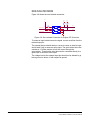
Wiring the Matrix to an External Alarm . . . . . . . . . . . . . . . . . 4-15
Wiring the Matrix Directly to a 4-Wire Audio Device . . . . . . . 4-16
Wiring the Matrix to Interface Modules . . . . . . . . . . . . . . . . . 4-17
ii
Clear-Com Communication Systems
Eclipse Matrix Installation Instruction Manual
FOR-22 4-Wire/Radio Interface Wiring . . . . . . . . . . . . . . . . . . . . 4-20
External Audio Devices . . . . . . . . . . . . . . . . . . . . . . . . . . . . . . 4-20
Call Signal Input. . . . . . . . . . . . . . . . . . . . . . . . . . . . . . . . . . . . 4-21
Relay Contacts . . . . . . . . . . . . . . . . . . . . . . . . . . . . . . . . . . . . 4-21
CCI-22 Party-Line Interface Wiring . . . . . . . . . . . . . . . . . . . . . . . 4-21
Clear-Com Party Lines General Discussion . . . . . . . . . . . . . . 4-22
TEL-14 Telephone Interface Wiring. . . . . . . . . . . . . . . . . . . . . . . 4-22
IMF-3 Interface Module Frame Wiring . . . . . . . . . . . . . . . . . . . 4-23
IMF-102 Interface Module Frame Wiring . . . . . . . . . . . . . . . . . 4-23
Connecting to the Telephone Line. . . . . . . . . . . . . . . . . . . . . . 4-24
Telephone Set . . . . . . . . . . . . . . . . . . . . . . . . . . . . . . . . . . . . . 4-25
Relay Contacts . . . . . . . . . . . . . . . . . . . . . . . . . . . . . . . . . . . . 4-25
RLY-6 Interface Wiring . . . . . . . . . . . . . . . . . . . . . . . . . . . . . . . . 4-25
IMF-3 Interface Module Frame Wiring . . . . . . . . . . . . . . . . . . . 4-26
To Matrix Frame . . . . . . . . . . . . . . . . . . . . . . . . . . . . . . . . . 4-26
To External Device . . . . . . . . . . . . . . . . . . . . . . . . . . . . . . . 4-27
IMF-102 Interface Module Frame Wiring . . . . . . . . . . . . . . . . . 4-28
Configuration . . . . . . . . . . . . . . . . . . . . . . . . . . . . . . . . . . . . . . 4-28
GPI-6 Interface Wiring. . . . . . . . . . . . . . . . . . . . . . . . . . . . . . . . . 4-29
IMF-3 Interface Module Frame Wiring . . . . . . . . . . . . . . . . . . . 4-29
To Matrix Frame . . . . . . . . . . . . . . . . . . . . . . . . . . . . . . . . . 4-29
To External Device . . . . . . . . . . . . . . . . . . . . . . . . . . . . . . . 4-29
IMF-102 Interface Module Frame Wiring . . . . . . . . . . . . . . . . . 4-30
Configuration . . . . . . . . . . . . . . . . . . . . . . . . . . . . . . . . . . . . . . 4-31
Wiring an ICS Panel Miscellaneous Connector . . . . . . . . . . 4-32
External Program Feed Input . . . . . . . . . . . . . . . . . . . . . . . . . . . 4-32
Binaural Headset (All Panels Except ICS-2003/2110/1016) . . . . 4-33
ICS-2003 Logic Input #1 and Logic Input #2. . . . . . . . . . . . . . . . 4-33
Mute Relay Contacts . . . . . . . . . . . . . . . . . . . . . . . . . . . . . . . . . . 4-34
Auxiliary Relay Contacts . . . . . . . . . . . . . . . . . . . . . . . . . . . . . . . 4-34
Wiring a Binaural Headset (ICS-2003) . . . . . . . . . . . . . . . . . 4-35
Wiring an ICS Panel OPT-100 Auxiliary Audio I/O Option. . 4-36
Auxiliary Audio Line Level Output . . . . . . . . . . . . . . . . . . . . . . . . 4-37
Hot Mic Output . . . . . . . . . . . . . . . . . . . . . . . . . . . . . . . . . . . . . . 4-37
SA (Studio/Stage Announce) Output. . . . . . . . . . . . . . . . . . . . . . 4-37
SA Relay . . . . . . . . . . . . . . . . . . . . . . . . . . . . . . . . . . . . . . . . . . . 4-37
Wiring an ICS Panel Accessory Connector . . . . . . . . . . . . . 4-38
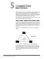
CONNECTING MATRICES . . . . . . . . . . . . . . . . . . . 5-1
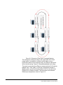
Intelligent Linking with Trunk Lines. . . . . . . . . . . . . . . . . . . . . 5-1
Base-Loop Linking (Eclipse PiCo/Eclipse-32 Matrix Only) . . . 5-5
Clear-Com Communication Systems
Eclipse Matrix Installation Instruction Manual
iii
Tie-Line (Audio Only) Linking . . . . . . . . . . . . . . . . . . . . . . . . . 5-5
GLOSSARY . . . . . . . . . . . . . . . . . . . . . . . . . . . . . . . 6-1
Eclipse Manuals . . . . . . . . . . . . . . . . . . . . . . . . . . . . . . . . . . . 6-5
Software Manuals . . . . . . . . . . . . . . . . . . . . . . . . . . . . . . . . . . . . . 6-5
Hardware Manuals . . . . . . . . . . . . . . . . . . . . . . . . . . . . . . . . . . . . 6-5
LIMITED WARRANTY . . . . . . . . . . . . . . . . . . . . . . . W-I
TECHNICAL SUPPORT & REPAIR POLICY. . . . . W-V
TECHNICAL SUPPORT POLICY. . . . . . . . . . . . . . . . . . . . . .W-v
RETURN MATERIAL AUTHORIZATION POLICY . . . . . . . . W-vi
REPAIR POLICY . . . . . . . . . . . . . . . . . . . . . . . . . . . . . . . . W-viii
iv
Clear-Com Communication Systems
Eclipse Matrix Installation Instruction Manual
FIGURES
Figure 2-1 IMF-3 Interface Frame Rear Panel................................. 2-4
Figure 2-2 IMF-102 Interface Frame Rear Panel............................. 2-4
Figure 3-1 PSU-101 to IMF-3 Wiring ............................................... 3-6
Figure 4-1 Computer DB-25F to Matrix DB-9M RS-232 Cable........ 4-5
Figure 4-2 Computer DB-9F to Matrix DB-9M RS-232 Cable.......... 4-5
Figure 4-3 Pin Assignments for LAN 1 and LAN 2 Connectors ....... 4-7
Figure 4-4 Wiring Matrix to Analog Panel Using RJ-45 ................... 4-9
Figure 4-5 Wiring Matrix to Digital Panel Using RJ-45 .................. 4-10
Figure 4-6 General-Purpose Outputs Connector Pinout................ 4-11
Figure 4-7 General-Purpose Inputs Connector Pinout .................. 4-12
Figure 4-8 Opto-Isolated Connection to Eclipse GPI Connector ... 4-13
Figure 4-9 Non-Isolated Connection to Eclipse GPI Connector .... 4-14
Figure 4-10 Alarm I/O Connector................................................... 4-15
Figure 4-11 Direct Eclipse Matrix Port Connection........................ 4-16
Figure 4-12 RLY-6/GPI-6 Daisy Chain Connection ....................... 4-19
Figure 4-13 Matrix Frame to IMF-3 Interface Connection.............. 4-19
Figure 4-14 Pinout of the DB-9M I/O Connectors for FOR-22s ..... 4-20
Figure 4-15 Pinout of the DB-9M Interface I/O Connectors for CCI-22 .
4-22
Figure 4-16 Wiring an IMF-3 Rear-Panel Assembly to a TEL-14 Interface ................................................................................................ 4-23
Figure 4-17 Wiring an IMF-102 Rear-Panel Assembly to a TEL-14 Interface ................................................................................................ 4-24
Figure 4-18 RJ-11 to DB-9 Adaptor for TEL-14 Interfaces ............ 4-25
Figure 4-19 Rear View of IMF-3 Frame ......................................... 4-27
Figure 4-20 RLY-6 Interface DB-9M Connector Pinout ................. 4-28
Figure 4-21 GPI-6 Interface DB-9M Connector Pinout .................. 4-30
Figure 4-22 GPI-6 Application Examples....................................... 4-30
Figure 4-23 Miscellaneous Connector Pin Configuration .............. 4-32
Figure 4-24 Binaural Headset Wiring............................................. 4-35
Figure 4-25 Auxiliary I/O Connector .............................................. 4-36
Figure 4-26 Accessory Panel Connector Pinout............................ 4-38
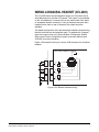
Figure 5-1 A Linked System on an Ethernet Network...................... 5-1
Figure 5-2 Example of Fiber-Optic Connected Matrices.................. 5-2
Figure 5-3 Dedicated Serial Port Audio Trunk Wiring...................... 5-3
Figure 5-4 Ethernet Wiring............................................................... 5-3
Figure 5-5 Matrices Linked Across Continents ................................ 5-4
Clear-Com Communication Systems
Eclipse Matrix Installation Instruction Manual
i
ii
Clear-Com Communication Systems
Eclipse Matrix Installation Instruction Manual
IMPORTANT SAFETY
INSTRUCTIONS
Please read and follow these instructions before operating an Eclipse
system. Keep these instructions for future reference.
Please read and follow
these instructions
before operating an
Eclipse system.
1. WARNING: To reduce the risk of fire or electric shock, do not
expose this apparatus to rain or moisture.
2. Do not use the apparatus near water.
3. Clean only with a dry cloth.
4. Do not block any ventilation openings. Install in accordance with
the manufacturer’s instructions. Install product according to the
installation directions of this manual.
5. Do not install near any heat sources such as radiators, heat
registers, stoves, or other apparatus (including amplifiers) that
produce heat. Do not place naked flame sources such as candles
on or near the matrix.
6. Do not defeat the safety purpose of the polarized plug or
grounding-type plug. A polarized plug has two blades with one
wider than the other. A grounding-type plug has two blades and a
third grounding prong. The wide blade or the third prong are
provided for your safety. If the provided plug does not fit into your
outlet, consult an electrician for replacement of the obsolete outlet.
7. Protect power leads from being walked on or pinched particularly
at plugs, at convenience receptacles, and at the point where they
exit from the apparatus.
Note: A “convenience receptacle” is an extra AC power outlet
located on the back of a piece of equipment, intended to
allow you to power other equipment.
8. Only use attachments/accessories specified by the manufacturer.
9. Use only with the cart, stand, tripod, bracket, or table specified by
the manufacturer, or sold with the apparatus. When a cart is used,
use caution when moving the cart/apparatus combination to avoid
injury from tip-over.
10. Unplug the apparatus during lightning storms or when unused for
long periods of time.
11. Refer all servicing to qualified service personnel. Servicing is
required when the apparatus has been damaged in any way, such
as a power-supply cord or plug is damaged, liquid has been spilled
or objects have fallen into the apparatus, the apparatus has been
exposed to rain or moisture, does not operate normally, or has
been dropped.
Please familiarize yourself with the safety symbols in Figure 1.
When you see these symbols on an Eclipse system, they warn
you of the potential danger of electric shock if the system is used
Clear-Com Communication Systems
Eclipse Matrix Installation Instruction Manual
iii
improperly. They also refer you to important operating and
maintenance instructions in the manual.
CAUTION
RISK OF ELECTRIC SHOCK
DO NOT OPEN
This symbol alerts you to the presence of uninsulated dangerous
voltage within the product’s enclosure that might be of sufficient
magnitude to constitute a risk of electric shock. Do not open
the product’s case.
This symbol informs you that important operating and maintenance instructions are included in the literature accompanying
this product.
Figure 1: Safety Symbols
iv
Clear-Com Communication Systems
Eclipse Matrix Installation Instruction Manual
1
INSTALLATION
OVERVIEW
INTRODUCTION
The Eclipse Matrix Installation Instruction Manual describes the steps
required to install an Eclipse matrix system and customize it. The
manual provides information about placing, powering, and wiring
components of the Eclipse system.
This manual describes how
to install an Eclipse matrix
system.
It is highly recommended that the instruction manual for the matrix to
be installed is read before attempting an installation. That manual
describes the specific Eclipse system hardware and defines many of
the concepts used in the system. An overall understanding of the
system is necessary to make maximum use of its vast capabilities.
Caution: Servicing instructions are for use by qualified personnel only.
To reduce the risk of electric shock, do not perform any
servicing other than that contained in the operating
instructions unless qualified to do so. Refer all servicing to
qualified service personnel.
Each product manual in the
Eclipse set gives additional
installation information.
The information in this manual is presented as follows:
Chapter 1. Installation Overview: Step-By-Step Installation Information
The first chapter provides a step-by-step installation guide for the
components of the Eclipse matrix system as received from the factory.
Chapter 2. Placing System Components
The second chapter describes the Eclipse matrix system’s component
location requirements, including a summary of component sizes.
Chapter 3. Powering System Components
The third chapter provides guidelines for providing AC power to the
system and for planning the powering of interface frames.
Chapter 4. Wiring System Components
The fourth chapter gives an overview of the various wiring systems for
connecting panels and interfaces to the matrix. This chapter contains
reference information necessary to wire all connectors in the Eclipse
system. However, many of the components have internal jumpers and
adjustments. Information on internal jumpers, adjustments, and device
specifications can be found in the individual manuals for each
component.
Clear-Com Communication Systems
Eclipse Matrix Installation Instruction Manual
1-1
Chapter 5. Connecting Matrices
The fifth chapter provides information on linking matrices.
1-2
Clear-Com Communication Systems
Eclipse Matrix Installation Instruction Manual
STEP-BY-STEP INSTALLATION
To install an Eclipse matrix system:
1. Verify the shipment.
2. Select locations for the components.
3. Determine the wiring requirements.
4. Install components in rack.
5. Install cables.
6. Connect cable and auxiliary wiring.
7. Connect to mains AC Power.
8. Configure the system with the Eclipse Configuration System (ECS)
software.
9. Verify the operation of the system.
1. Verify the Shipment
When the equipment is received inspect the boxes for shipping
damage. Report any shipping damage to the carrier. The Eclipse
matrix system distributor is not responsible for shipping damage.
Check the packing list and verify that every item on the list has been
received. Pay special attention to options that have been installed in
intercom panels. Panel options are printed on each panel’s rear cover.
Save all packing materials (boxes, Styrofoam filler, etc.), since they will
be needed if any item must be returned because it was shipped by
mistake, because of malfunction, or for warranty service.
2. Select Locations for the Components
Select locations for the central matrix, intercom panels, interface
modules, computer, and any other system components. For additional
information on limitations imposed on location by the Eclipse matrix
system see Chapter 2, “Placing System Components.”
3. Determine the Wiring Requirements
Eclipse requires shielded category-5 (CAT5) cable with RJ-45
connectors on either end; however, there are various methods
available to deliver these cables from one place to another. For more
information on RJ-45 connectors and their installation, refer to Chapter
4, “Wiring System Components.”
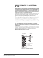
All Eclipse panels have built-in RJ-45 connectors. Shielded CAT5
cables are available with RJ-45 terminations already installed. Bulk
RJ-45 connectors can be bought and installed on custom length
cables.
Clear-Com Communication Systems
Eclipse Matrix Installation Instruction Manual
1-3
4. Install Components in Rack
Install the matrix in a standard Electronics Industry Association 19-inch
wide (48.26 cm) equipment rack. The matrix requires adequate
ventilation. Leave at least 2 inches (50.8 mm) of clearance on all sides
of the matrix to ensure proper airflow. Do not block ventilation vents.
Check the position of circuit cards, power supplies, and rear-connector
panels. Refer to the appropriate manual in the Eclipse set of manuals
for detailed information on installing a particular frame in the rack.
• For matrices, refer to the Eclipse Omega Matrix Instruction Manual
(part 810290Z), the Eclipse Median Matrix Instruction Manual (part
810347Z), the Eclipse Pico Matrix Instruction Manual (part
810348Z) or the Eclipse-32 Matrix Instruction Manual (part
810315Z) as appropriate for complete installation requirements.
• For interface frames, refer to the appropriate instruction manual for
either the IMF-3, IMF-102, or DIF-102 interface frame (part
810313Z).
5. Install Cables
Install the wiring between the Eclipse matrix and the system
components. Usually the connectors are wired to the cables after the
cables are routed. For further information refer to Chapter 4, “Wiring
System Components.”
Install the DC power cables that connect the power supply or supplies
to the IMF-3 interface frame. Connect the mains AC power cables for
the matrix frame and each panel. For further information refer to
Chapter 3, “Powering System Components.”
6. Connect Cables and Auxiliary Wiring
There are several different types of wiring necessary to connect an
Eclipse system. The following is a summary of the subjects.
Analog Panel Wiring - Connect the intercom panels to the matrix using
shielded CAT5 4-twisted pair cables with RJ-45 connectors. At each
panel there may be other connector wiring necessary depending on
the options and accessories installed.
Digital Panel Wiring - The DIF-102 interface frame holds two DIG-2
interface modules. Each DIG-2 interface module connects two digital
intercom panels to the matrix. Connect the intercom panels to the
DIG-2 interface using double shielded (braid and foil) 24 AWG
conductor CAT-6 enhanced STP cable (CAT-6E) with RJ-45
connectors. At each panel there may be other connector wiring
necessary depending on the options and accessories installed.
Interface Wiring - Connect the interface modules to the matrix using
shielded CAT5 4-twisted pair cables with RJ-45 connectors. Each
interface type requires particular wiring schemes on the DB-9
1-4
Clear-Com Communication Systems
Eclipse Matrix Installation Instruction Manual
connectors on the rear of the associated IMF-3 frame per the actual
application. Special interfaces such as the RLY-6 and GPI-6 are
connected directly via an RJ-45 connector on the rear of the matrix to
the appropriate interface input connector on an IMF-3 frame.
External Computer - To connect the computer to the Eclipse matrix,
use the supplied DB-9 cable or a commercially available shielded
RS-232 cable. If an RS-232 cable is used, be sure it provides the
connections described in "Wiring for Serial Connection" in Chapter 4.
Note: If the ECS computer does not have a serial port, but only
offers USB, adapters are available from computer parts
suppliers.
The matrix can be connected to an Ethernet network through the two
standard RJ-45 Ethernet connectors labeled LAN 1 and LAN 2 on the
Eclipse matrix. Ethernet connection allows one or more matrices to be
controlled from one or more computers on a network. See Chapter 4
for more information.
Note: If these ports are used a ferrite must be added to the socket
end of each cable. A suitable ferrite is Würth Electronik part:
74271132.
Note: Shielded CAT-5 cable should be used.
External Alarm Connection - Eclipse matrices have built-in fault alarm
systems. If it is desirable to repeat this alarm with some remote alarm,
relay contacts are available on the matrix frame’s rear panel. If some
external alarm condition needs to be added to the frame’s alarm
system, the same connector on the rear panel ALARM I/O will allow an
external contact closure to be connected to the frame’s alarm system.
Note: Shielded cables should be used.
7. Connect to Mains AC Power
Each component of the Eclipse system requires AC power except for
the IMF-3 and some expansion panels. The IMF-3 requires an external
power supply. The XP-type expansion panels receive power from the
panels to which they are connected.
Matrices
Eclipse matrices have two separate AC power connectors for two
separate power supplies in the system. Either power supply will
completely power a system, providing 100% power redundancy. If the
two power supplies are connected to different AC power sources and
one of the power supplies loses power, the other will continue to
operate the system.
AC voltage for the matrices and the PSU-101 can be 100 to 240 VAC
without any switching or fuse changes.
Clear-Com Communication Systems
Eclipse Matrix Installation Instruction Manual
1-5
Panels
V-Series Panels
Each V-Series panel (V12LD, V12PD, V24LD, V24PD, V12LDD,
V12PDD, V12LDE, V12PDE) has an external power supply. AC
voltage for these panels can be 100 to 240 VAC without any switching
or fuse changes.
4000 Series II Panels
Each 4000 Series II panel (4212, 4215, 4222, 4224, 4226, 4294, 4203,
4206, 4230, 4230V) has an external power supply. AC voltage for
these panels can be 100 to 240 VAC without any switching or fuse
changes.
ICS Panels and i-Stations
Each ICS-2003 and ICS-1016 panel has an external power supply. A
bracket has been provided to mount this external supply if necessary.
AC voltage for these panels can be 90 to 260 VAC without any
switching or fuse changes.
The ICS-102/92/62/52 panels have wall-mounted transformers for 110
VAC and in-line transformers for 220 VAC. Confirm that the correct
ones have been supplied for the installation.
The i-Stations have internal power supplies, with removable AC power
cords. The power supplies are “universal,” operating over a voltage
range of 90 to 245 VAC and 50 to 60 Hz. The maximum dissipation is
40 W.
Each panel will need to be plugged into an AC source at its location.
8. Configure the System
The Eclipse Configuration System (ECS) programming software allows
the system to be configured for the operating environment. With this
software a system administrator can assign port or panel names,
declare interface port functions, assign “labels” to keys on panels, and
perform many other functions. Refer to the Eclipse Configuration
System Manual for instructions on using the software.
9. Verify the Operation of the System
Once the system is configured, a detailed check of each panel,
interface connection, control function, and other features should be
performed. Each audio path, relay output, and control input needs to
be exercised to verify proper operation. Each software function, such
as Party Lines, ISO, and IFB must be verified. Each installation is
different, so it is beyond the scope of this manual to outline in detail
this phase.
1-6
Clear-Com Communication Systems
Eclipse Matrix Installation Instruction Manual
Matrix Indicators to Verify
Eclipse Omega
There are many lights on the front of the matrix that indicate its
operational status. Proper operation of the matrix is indicated by the
following:
1. The two power supply lights, labeled “+5V” and “+3.3V” illuminate
green steadily to indicate that the power supplies are present.
2. The dot-matrix array of lights displays a number to indicate which of
the four stored configurations in the CPU card’s memory is currently
operating. The configuration number displays for a short time after
power up or upon configuration selection.
3. The “OK” light flashes to indicate that the CPU card software is
running.
4. The “master” light illuminates steadily on the currently active CPU
card, indicating that the CPU card is properly installed and operating
correctly.
Eclipse Median
There are many lights on the front of the matrix that indicate its
operational status. Proper operation of the matrix is indicated by the
following:
1. The two power supply lights, labeled “+5V” and “+3.3V” illuminate
green steadily to indicate that the power supplies are present.
2. The dot-matrix array of lights displays a number to indicate which of
the four stored configurations in the CPU card’s memory is currently
operating. The configuration number displays for a short time after
power up or upon configuration selection.
3. The “OK” light flashes to indicate that the CPU card software is
running.
4. The “master” light illuminates steadily on the currently active CPU
card, indicating that the CPU card is properly installed and operating
correctly.
Eclipse Pico
The following front-panel indicators indicate a properly operating
Eclipse Pico matrix:
1. The two PSU alarm lights, labeled “1” and “2” do not illuminate
under normal operating conditions.
2. One of the four green configuration lights illuminates steadily to
identify the currently active configuration.
3. The “OK” light flashes to indicate that the Eclipse-32 is running
successfully.
4. If the matrix is connected to a local area network, the green LAN UP
light illuminates steadily. The yellow RX light flashes when data is
being received.
Clear-Com Communication Systems
Eclipse Matrix Installation Instruction Manual
1-7
Eclipse-32
The following front-panel indicators indicate a properly operating
Eclipse-32 matrix:
1. The two PSU alarm lights, labeled “1” and “2” do not illuminate
under normal operating conditions.
2. One of the four green configuration lights illuminates steadily to
identify the currently active configuration.
3. The “OK” light flashes to indicate that the Eclipse-32 is running
successfully.
4. If the matrix is connected to a local area network, the green LAN UP
light illuminates steadily. The yellow RX light flashes when data is
being received.
5. An illuminated port status light indicates that communications are
running properly between the matrix and the device connected to
that port.
1-8
Clear-Com Communication Systems
Eclipse Matrix Installation Instruction Manual
2
PLACING SYSTEM
COMPONENTS
COMPONENT LOCATION REQUIREMENTS
This chapter provides guidelines for placing and arranging the main
components of an Eclipse system, including:
• Eclipse matrices
• Interface frame(s) and power supplies
• Intercom panels and accessory panels
• External computer
ECLIPSE MATRICES
The Eclipse matrix is the central connecting point of the system. All
panels, interfaces, and external devices must be connected directly to
the Eclipse matrix, so it should be centrally located. The system matrix
may be an Eclipse Omega, Eclipse Median, Eclipse Pico or an
Eclipse-32, depending on site requirements.
A matrix should be placed in the center portion of a standard
Electronics Industry Association 19-inch wide (48.26 cm) rack,
allowing easy access to the matrix’s port connectors. Some planning is
also necessary for the dressing of cables in the rack because of the
large number of cables.
Note: A “rack unit” refers to a standardized unit of space in an
Electronics Industry Association equipment rack. One rack
unit is 1.75 inches high and 19 inches wide (or 482.6 mm by
44.45 mm). Each increasing “rack unit” adds 1.75 inches to
the area vertically, while staying at 19 inches horizontally.
Eclipse Omega Matrix
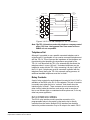
The Eclipse Omega matrix requires six vertical rack units (10.5 inches
or 267 mm) in a standard Electronics Industry Association 19-inch
wide (48.26 cm) rack. There are two power supplies in each matrix. A
modular removable alarm module fitted beneath the two power
supplies has two fans that deliver forced air cooling. The primary fan
runs continuously. If the temperature in the matrix exceeds a set
threshold and extra cooling is required, a secondary fan switches on to
increase the air flow in the matrix.
The “fan-on” alarm light on the front of the alarm module illuminates
red to indicate that the secondary fan is on. The red “fan-fail” alarm
light illuminates when either fan stops rotating correctly. These alarm
Clear-Com Communication Systems
Eclipse Matrix Installation Instruction Manual
2-1
lights allow the system operator to identify and correct the alarm
conditions. See the Eclipse Omega Matrix Instruction Manual (part
810290Z) for more details.
Caution: It is mandatory that the air flow through an Eclipse Omega
matrix from the bottom to the top is unimpeded. If other
equipment is mounted above and below the matrix that
impedes the air flow through the matrix, it will be necessary
to leave 1 RU of empty space above and below the Eclipse
Omega matrix as over-heating will occur if this is not done. If
the matrix is mounted in a portable case this air flow must not
be impeded.
Eclipse Median Matrix
The Eclipse Median matrix requires six vertical rack units (10.5 inches
or 267 mm) in a standard Electronics Industry Association 19-inch
wide (48.26 cm) rack. There are two power supplies in each matrix. A
modular removable alarm module fitted beneath the two power
supplies has two fans that deliver forced air cooling. The primary fan
runs continuously. If the temperature in the matrix exceeds a set
threshold and extra cooling is required, a secondary fan switches on to
increase the air flow in the matrix.
The “fan-on” alarm light on the front of the alarm module illuminates
red to indicate that the secondary fan is on. The red “fan-fail” alarm
light illuminates when either fan stops rotating correctly. These alarm
lights allow the system operator to identify and correct the alarm
conditions. See the Eclipse Median Matrix Instruction Manual (part
810347Z) for more details.
Caution: It is mandatory that the air flow through an Eclipse Median
matrix from the bottom to the top is unimpeded. If other
equipment is mounted above and below the matrix that
impedes the air flow through the matrix, it will be necessary
to leave 1 RU of empty space above and below the Eclipse
Median matrix as over-heating will occur if this is not done. If
the matrix is mounted in a portable case this air flow must not
be impeded.
Eclipse Pico Matrix
The Eclipse Pico matrix requires one vertical rack unit (1.75 in. or
44.45 mm) in a standard Electronics Industry Association 19-inch
(48.26 cm) rack. A temperature-controlled fan cools the Eclipse Pico
and forces air through the unit horizontally. An alarm light on the front
panel of the Eclipse Pico alerts the system operator when the
temperature-controlled fan activates.
2-2
Clear-Com Communication Systems
Eclipse Matrix Installation Instruction Manual
Caution: It is mandatory that the air flow across an Eclipse Pico
matrix is unimpeded. The air flow in a standard 19-inch
(48.26 cm) rack should be sufficient. If the matrix is mounted
in a portable case, be sure the air flow is not impeded.
Eclipse-32 Matrix
The Eclipse-32 matrix requires one vertical rack unit (1.75 in. or 44.45
mm) in a standard Electronics Industry Association 19-inch (48.26 cm)
rack. A temperature-controlled fan cools the Eclipse-32 and forces air
through the unit horizontally. An alarm light on the front panel of the
Eclipse-32 alerts the system operator when the temperature-controlled
fan activates.
Caution: It is mandatory that the air flow across an Eclipse-32 matrix
is unimpeded. The air flow in a standard 19-inch (48.26 cm)
rack should be sufficient. If the matrix is mounted in a
portable case, be sure the air flow is not impeded.
INTERFACE FRAME(S) AND POWER SUPPLIES
Interface modules convert the 4-wire signals of a central matrix port to
some other form of communication, such as for telephones, camera
intercoms, two-way radios, and so on. In this way, non-4-wire devices
can communicate with the central matrix.
Each interface module connects to both the central matrix and to the
non-4-wire device through cable attached to hardware connectors on
the rear of the interface module. To house these interface modules,
Clear-Com offers three types of interface frames, which are described
in the following sections.
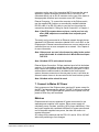
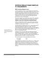
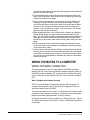
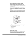
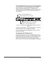
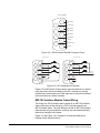
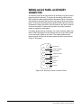
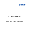
IMF-3 Interface Module Frame
The IMF-3 interface frame holds up to 11 interface modules in three
rack units (3 RU) of a standard Electronics Industry Association
19-inch wide (48.26 cm) rack. The frame holds a modular,
rear-mounted connector panel for each interface, containing two RJ-45
connectors for connecting cable to matrix ports, and two DB-9
connectors for connecting cable to non-4-wire devices. Figure
2-1illustrates the rear panel of an IMF-3 interface frame, with 11
rear-panel assemblies installed.
The frame uses an external PSU-101 rack-mounted power supply to
supply power to the interface modules. A second PSU-101 can be
attached for redundancy.
Clear-Com Communication Systems
Eclipse Matrix Installation Instruction Manual
2-3
POWER SUPPLY #1
CH. A
Matrix
CH. A
Matrix
CH. A
Matrix
CH. A
Matrix
CH. A
Matrix
CH. A
Matrix
CH. A
Matrix
CH. A
Matrix
CH. A
Matrix
CH. A
Matrix
CH. A
Matrix
CH. A
I/O
PHONE
LINE A
CH. A
I/O
PHONE
LINE A
CH. A
I/O
PHONE
LINE A
CH. A
I/O
PHONE
LINE A
CH. A
I/O
PHONE
LINE A
CH. A
I/O
PHONE
LINE A
CH. A
I/O
PHONE
LINE A
CH. A
I/O
PHONE
LINE A
CH. A
I/O
PHONE
LINE A
CH. A
I/O
PHONE
LINE A
CH. A
I/O
PHONE
LINE A
CH. B
Matrix
CH. B
Matrix
CH. B
Matrix
CH. B
Matrix
CH. B
Matrix
CH. B
Matrix
CH. B
Matrix
CH. B
Matrix
CH. B
Matrix
CH. B
Matrix
CH. B
Matrix
CH. B
I/O
PHONE
LINE B
CH. B
I/O
PHONE
LINE B
CH. B
I/O
PHONE
LINE B
CH. B
I/O
PHONE
LINE B
CH. B
I/O
PHONE
LINE B
CH. B
I/O
PHONE
LINE B
CH. B
I/O
PHONE
LINE B
CH. B
I/O
PHONE
LINE B
CH. B
I/O
PHONE
LINE B
CH. B
I/O
PHONE
LINE B
CH. B
I/O
PHONE
LINE B
POWER SUPPLY #2
Figure 2-1: IMF-3 Interface Frame Rear Panel
Note: The IMF-3 frame has an individual rear panel for each
interface. All interfaces use the same rear panel; however
the use of the rear-panel connectors will vary with the type
of interface.
Each interface features indicators and controls that must be accessible
to system operators, so put the interface module frame(s) in a
convenient location. Usually interface module frames are located near
the matrix frame, but they can be located farther away. The maximum
distance between the matrix frame and the interface frame is 500 feet
(150 meters).
Each Eclipse frame contains its own power supplies and does not
supply any power for interfaces. A separate power supply (PSU-101) is
only necessary for interfaces mounted in IMF-3 frames. If redundant
power supply pairs are used for interfaces, mount them together. For
detailed information on power supply requirements, refer to Chapter 3,
“Powering System Components”.
It is required that an extra rack unit (1.75 in. or 44.45 mm) is left above
and below each external power supply unit. This allows for needed
cooling for larger system loads.
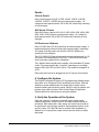
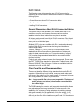
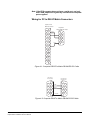
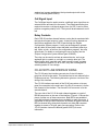
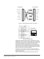
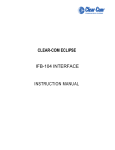
IMF-102 Interface Module Frame
The IMF-102 interface frame has slots for two interface modules in one
rack unit (1 RU) of a standard Electronics Industry Association 19-inch
wide (48.26 cm) rack.
It has an internal power supply and a connector for a redundant power
supply. Its rear input/output connector panel has two RJ-45 connectors
and DB-9 connectors for each of the two interface modules. Figure 2-2
illustrates the rear panel of an IMF-102 interface frame, with two
installed rear-panel assemblies.
CH.A
Marix
CH.A
I/O
CH.B
Matrix
CH.B
I/O
CH.A
Marix
CH.A
I/O
CH.B
Matrix
CH.B
I/O
Figure 2-2: IMF-102 Interface Frame Rear Panel
2-4
Clear-Com Communication Systems
Eclipse Matrix Installation Instruction Manual
DIF-102 Interface Module Frame
The DIF-102 interface frame has slots for two digital DIG-2 interface
modules in one rack unit (1 RU) of a standard Electronics Industry
Association 19-inch (48.26 cm) rack. DIG-2 interface modules allow
the matrix to connect to digital versions of Clear-Com intercom panels.
The DIF-102 frame is powered by one or two (for redundancy) external
AC mains to 24 VDC power supplies via locking DIN connectors on the
DIF-102 rear panel. All other voltages are derived directly or indirectly
from the 24 VDC on the DIG-2 front and rear cards.
The DIF-102 should be located in the same building as the Eclipse
frame. It can be located up to 3000 feet (1000 meters) from an Eclipse
frame.
INTERCOM PANELS AND EXPANSION PANELS
Locate all intercom panels at comfortable heights for operation. Leave
at least 2 inches (50.8 mm) of clearance behind the panel chassis to
allow for cable connectors. In some low-light conditions, the
front-panel display for the ICS-2003 may be too bright. Refer to the
ICS-2003 manual for “display brightness adjustment” (part 810303Z).
Accessory panels such as the XPL, AP, or EXP that are intended to
expand or enhance the operation of panels are usually mounted just
above or below the panel with which they are associated. They can be
located up to 25 ft. (7.62 m) away from the panel. A 6-ft. (1.8 m) cable
is supplied to connect them.
Expansion panels such as the V12LDE, V12PDE, PD4203, PD4206,
PD4230 and PD4230V may be mounted as required.
Panels should not be more than 3,000 ft. (1000 m) from the Eclipse
matrix frame to which they are connected.
EXTERNAL COMPUTER
The Eclipse Configuration System (ECS) runs on an external computer
that connects to the matrix frame via a standard PC serial port to a
DB-9 RS-232 connector. The maximum recommended length of the
cable is approximately 10 feet (3.04 meters).
Note: If the ECS computer does not have a serial port, but only
offers USB, adapters are available from computer parts
suppliers.
ECS can also use an Ethernet network connected to the frame through
the two standard RJ-45 Ethernet connectors labeled LAN 1 and LAN 2.
Ethernet connection allows single or multiple PCs on the network to
control, configure, monitor, and diagnose single or multiple matrices.
Clear-Com Communication Systems
Eclipse Matrix Installation Instruction Manual
2-5
2-6
Clear-Com Communication Systems
Eclipse Matrix Installation Instruction Manual
3
POWERING SYSTEM
COMPONENTS
POWER REQUIREMENTS
Each matrix is equipped with
two power supplies that can
be connected to separate
branches of AC mains,
providing redundancy for the
power supplies and the
power sources.
Power requirements differ for each component of an Eclipse system.
This chapter gives guidelines for providing power to the following
components:
• Matrices
• V-Series panels
• 4000 Series II panels
• i-Series intercom panels
• ICS-2003 intercom panels
• ICS-1008/ICS-1016 intercom panels
• ICS-52/62/92/102 intercom panels
• XPL-12/22 display expansion panels and AP-22 assignment
panels
• Interface frames
MATRICES
Electrical power for an Eclipse Omega, Median or Pico matrix or for an
Eclipse-32 matrix originates from AC mains line current, which in turn
provides power to the matrix’s internal DC power supplies. Each matrix
is equipped with two power supplies that can be connected to separate
branches of AC mains, providing redundancy for the power supplies
and the power sources.
If an AC power source shuts off for any reason, a matrix can continue
to operate from the second AC power source. If one power supply fails,
a matrix can continue to operate from the second supply.
If one of the two DC power supplies fails, an “alarm” failure condition
will activate to provide the system operator with an opportunity to
repair or replace the supply while the second supply powers the
system.
Eclipse Omega Matrix
The Eclipse Omega matrix has two internal, Euro Cassette, plug-in
power supplies. Each of the power supplies must be connected to a
dedicated branch of AC mains power. The matrix will continue to
operate even if one of the AC power branches fails.
Clear-Com Communication Systems
Eclipse Matrix Installation Instruction Manual
3-1
Clear-Com ships each matrix with two power supplies already
installed. When the matrix is received, connect each of the power
supplies to a dedicated branch of AC mains power using the IEC
power connectors on the Eclipse Omega frame’s rear panel.
A fully equipped Eclipse Omega frame requires 100 to 240 VAC at 50
to 60 Hz with a maximum dissipation of 300 W.
Eclipse Median Matrix
The Eclipse Median matrix has two internal, Euro Cassette, plug-in
power supplies. Each of the power supplies must be connected to a
dedicated branch of AC mains power. The matrix will continue to
operate even if one of the AC power branches fails.
Clear-Com ships each matrix with two power supplies already
installed. When the matrix is received, connect each of the power
supplies to a dedicated branch of AC mains power using the IEC
power connectors on the Eclipse Median frame’s rear panel.
A fully equipped Eclipse Median frame requires 100 to 240 VAC at 50
to 60 Hz with a maximum dissipation of 300 W.
Eclipse Pico Matrix
The Eclipse Pico matrix has two internal power supply units. One
power supply unit can power an entire matrix; the second unit provides
a backup in case of an equipment failure.
In addition, the two supplies have separate IEC connectors to AC
mains power, and are designed for completely automatic and
transparent changeover between supplies in the event of an outage on
one of the AC mains circuits.
The power supplies are “universal”, operating over a voltage range of
100 to 240 VAC at 50 to 60 Hz.
An Eclipse Pico matrix requires 100 to 240 VAC at 50 to 60 Hz with a
maximum dissipation of 40 W.
Eclipse-32 Matrix
The Eclipse-32 matrix has two internal power supply units. One power
supply unit can power an entire matrix; the second unit provides a
backup in case of an equipment failure.
In addition, the two supplies have separate IEC connectors to AC
mains power, and are designed for completely automatic and
transparent changeover between supplies in the event of an outage on
one of the AC mains circuits.
The power supplies are “universal,” operating over a voltage range of
100 to 240 VAC at 50 to 60 Hz
3-2
Clear-Com Communication Systems
Eclipse Matrix Installation Instruction Manual
An Eclipse-32 matrix requires 100 to 240 VAC at 50 to 60 Hz with a
maximum dissipation of 40W.
INTERCOM PANELS
V-Series Panels and Expansion Panels
Each V-Series panel or expansion panel has a separate external DC
power supply. The power supply is “universal”, operating over a
voltage range of 100 to 240 VAC at 50 to 60 Hz. The maximum
dissipation is 50W.
4000 Series II Panels and Expansion Panels
Each 4000 Series II panel or expansion panel has a separate external
DC power supply. The power supply is “universal”, operating over a
voltage range of 100 to 240 VAC at 50 to 60 Hz. The maximum
dissipation is 30W.
i-Series Intercom Panels
Each i-Station has an internal power supply, with a removable AC
power cord. The power supply is “universal”, operating over a voltage
range of 90 to 245 VAC and 50 to 60 Hz. The maximum dissipation is
40W.
ICS-2003 Intercom Panels
Each ICS-2003 intercom panel has a separate external DC power
supply. The power supply is “universal,” operating over a voltage range
of 90 to 260 VAC at 45 to 65 Hz. The maximum dissipation is 30W.
ICS-1008/ICS-1016 Intercom Panels
Each ICS-1008/ICS-1016 intercom panel has a separate external DC
power supply. The power supply is “universal”, operating over a
voltage range of 90 to 260 VAC at 45 to 65 Hz. The maximum
dissipation is 30W.
ICS-52/62/92/102 Intercom Panels
Each ICS-52/62/92/102 intercom panel is powered by a transformer
that runs off of AC mains power: the 120-V transformer requires a
two-conductor wall outlet, and is housed in a 2 x 2 x 3 in. (5 x 5 x 7.6
cm) direct plug-in module; the 240-V transformer requires a
three-conductor wall outlet, and is housed in a 2 x 3 x 5 in. (5 x 7.6 x
12.7 cm) box located in the middle of its cable’s length. Each
transformer connects to each compact panel with the 2.1 mm coaxial
power connector on the rear of the panel.
An ICS-102/92/62/52 intercom panel requires 90 to 125 or 210 to 250
VAC at 45 to 65 Hz with a maximum dissipation of 40W.
Clear-Com Communication Systems
Eclipse Matrix Installation Instruction Manual
3-3
XPL-12/22 Display Expansion Panels and AP-22
Assignment Panels
XPL-12/22 display expansion panels and AP-type assignment panels
require an external transformer identical to those used with the 1 RU
panels (90 to 125 or 210 to 250 VAC at 45 to 65 Hz with a maximum
dissipation of 40W).
3-4
Clear-Com Communication Systems
Eclipse Matrix Installation Instruction Manual
INTERFACE MODULE FRAME POWER SUPPLY REQUIREMENTS
IMF-3 Interface Module Frame
As a rule-of-thumb, one PSU-101 power supply unit is required for
every two IMF-3 frames. There are two exceptions to this rule. The first
exception occurs when the frames have a large number of CCI-22
party-line interfaces which require no DC power from the IMF-3 frame.
However, an IMF-3 with only CCI-22 interfaces still needs to be
connected to a PSU-101 as the IMF frame itself needs some DC
power for the circuitry on its rear panel.
The second exception occurs when using multiple TEL-14 telephone
interfaces. An IMF-3 interface frame will only power eight TEL-14
interfaces. If more TEL-14 interfaces are required, they must be
installed in a second IMF-3 frame with a second power supply.
A PSU-101 requires 90 to 260 VAC at 45 to 65 Hz with a maximum
dissipation of 80 W. A PSU-101 connected for redundancy requires
very little AC current unless it is used.
For more information on
interface frames, refer to the
Interface Frames Instruction
Manual.
An audible alarm is included in the PSU-101, and an additional set of
alarm-relay contacts are provided on the supply. Clear-Com
recommends that these contacts be connected to the external alarm
input of the matrix frames. If any of the power supplies in the PSU-101
fails, it would cause a system alarm. LEDs on the front of the
PSU-101s will indicate the failure.
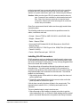
Installing two PSU-101 power supplies per application provides
redundancy because either of the two PSU-101 power supplies can
power a complete system. If one fails, it can be removed without
interruption of the entire system. Rear panel connectors provide easy
parallel connection to the IMF-3 Interface Module Frame.
The current capacities of the power supplies are as follows:
• +9 V analog
3.0 A
• -9 V analog
3.0 A
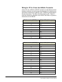
The following chart provides the current drain of the +/- analog power
supplies for all components in the system. Some devices, such as
interfaces, have a varying current depending on the operation of
features. In applications where it is possible to activate all operating
features of all components used, use the maximum current column for
planning.
Clear-Com Communication Systems
Eclipse Matrix Installation Instruction Manual
3-5
Component
Average
Current
Maximum
IMF-3 Frame
0.20 A
0.20 A
CCI-22
0.00 A
0.00 A
FOR-22
0.07 A
0.15 A
TEL-14
0.28 A
0.37 A
RLY-6
0.10 A
0.15 A
GPI-6
0.02 A
0.02 A
Table 3-1: Interface Current Consumption
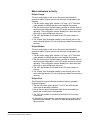
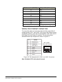
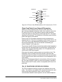
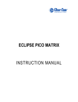
Figure 3-1 shows the PSU-101 to IMF-3 wiring possibilities.
PSU-101
PSU-101
IMF-3
IMF-3
IMF-3
IMF-3
IMF-3
PSU-101
Figure 3-1: PSU-101 to IMF-3 Wiring
IMF-102 Interface Module Frame
The IMF-102 interface frame has an internal power supply and a
rear-panel connector to provide redundant power. The IMF-102
requires 90 to 250 VAC with a maximum dissipation of 20 watts.
DIF-102 Interface Module Frame
The DIF-102 interface frame is powered by one or two (for
redundancy) external AC mains to 24 VDC power supplies via locking
DIN connectors on the DIF-102 rear panel. All other voltages are
derived directly or indirectly from the input 24 VDC on the DIG-2 front
and rear cards.
The DIF-102 frame has a PSU fail-alarm output provided by Form C
relay change-over contacts made available on a 9-way make D
connector on the DIF-102 rear panel.
3-6
Clear-Com Communication Systems
Eclipse Matrix Installation Instruction Manual
4
WIRING SYSTEM
COMPONENTS
SUMMARY OF WIRING SYSTEMS
This chapter describes how to connect an Eclipse matrix to its remote
panels and interfaces and to other Eclipse matrices using fiber-optic
cable. Most panels and interfaces connect to a matrix via single 4-pair
shielded RJ-45 terminated cables.
For more detail about component placement, specifications of
individual products, and internal adjustments, refer to the individual
manual for each product. To configure panels and interfaces, refer the
Eclipse Configuration System (ECS) Manual (part 810299Z).
The following wiring topics are discussed:
• Wiring RJ-45 cables.
• Wiring an Eclipse matrix to an external computer, to a local area
network, to analog and digital intercom panels, to general-purpose
outputs, to general-purpose inputs, to an external alarm, and
directly to a 4-wire audio device.
• Using E-FIB cards to connect Eclipse Omega and Median matrices
using fiber-optic cable.
• Wiring an Eclipse matrix to the following interfaces: FOR-22 interface,
CCI-22 interface, TEL-14 interface, RLY-6 interface, and GPI-6
interface.
• Wiring an ICS panel miscellaneous connector.
• Wiring an OPT-100 auxiliary audio I/O option connector.
• Wiring an ICS panel accessory connector.
Note: Single-pair digital wiring requires double-shielded 24 AWG
conductor CAT-6E enhanced STP cable.This wiring is
discussed only in general in this manual. For more detailed
instructions, refer to the individual manual for each product.
Clear-Com Communication Systems
Eclipse Matrix Installation Instruction Manual
4-1
RJ-45 CABLES
The following section discusses the use of RJ-45 connectors for
connecting an Eclipse frame to panels and interfaces. It includes the
following topics:
• General discussion about RJ-45 connector cables
• Clear-Com kits and recommendation
• Installing RJ-45 connectors.
General Discussion About RJ-45 Connector Cables
The system wiring is with shielded CAT5 twisted cable with RJ-45
connectors on either end; however, there are various methods
available to deliver these cables from one place to another.
All Eclipse matrix panels have built-in RJ-45 connectors. Direct 4-pair
cable with RJ-45 connectors on either end can connect an Eclipse
matrix port to an individual panel.
Shielded CAT5 cables are available with RJ-45 terminations already
installed. Bulk RJ-45 connectors can be bought and installed on
custom length cables.
The term “category 5” (CAT5) refers to a communications cable
standard that calls out transmission characteristics of twisted-pair
cables for data communication use. For each increasing “category”
(CAT) number the guaranteed bandwidth for data communication
purposes is higher.
For the 4-pair wiring scheme between the frame panels, Eclipse uses
the AT&T T568B wiring standard for data cables. Cables for use with
Ethernet 10-BASE-T are of this type. Cables are available in solid or
stranded wire in #24 or #26 AWG.
Clear-Com Kits and Recommendation
There are at least five different wiring standards that use the RJ-45
connector. Although they look identical, many pre-made cables and
utility items, like couplers, will not work properly. It is essential to know
what wiring standard is used in any accessories.
Note: Long runs with flat cable are not acceptable. The data and
audio pairs are not twisted, therefore the crosstalk within
the cable is high.
The T568B standard is a mature, well supported standard that allows
many advantages. Fast easy termination of cables as well as the
availability of a vast array of wiring adapters and patching systems
allow great versatility for all applications of intercom wiring. RJ-45
connectors are easy and fast to connect to equipment. T568A cables
differ only on the color of the insulation on pairs 2 and 3. If the ends are
4-2
Clear-Com Communication Systems
Eclipse Matrix Installation Instruction Manual
not being removed from a pre-made cable this will not be a problem.
Be aware that if the ends are removed from a pre-made cable to
shorten or to punch onto blocks, pair 2 and 3 colors may be different.
Caution: Make sure the type of RJ-45 connector matches the wire
type. Connectors are available for both stranded and solid
wire. Clear-Com intercom panels do not require keyed
connectors. Please refer to the following list for connector
vendor and port numbers.
Clear-Com recommends that all cables are thoroughly tested before
connecting them.
The following products are recommended as possible sources for
cables, connectors and tools:
• Crimper - Siemon PT908 or AMP 2-231652-1 with 853400-1 dies
• Stripper - Siemon CPT
• Tester - Siemon STM-8
• Connector RJ-45 Shielded 26-22 AWG Stranded or Solid RJ-45 Siemon PS-8-8
• CINCH FA-25PS/1-LF 25W D-type in-line 1000pF filter (UK supplier:
Farnell 111-4108)
• Ferrite - Würth Electronik part: 74271132
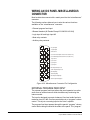
Installing RJ-45 Connectors
RJ-45 connectors can be a challenge to install correctly unless some
of the following techniques are followed. Like most wiring skills, once
the “tricks” are known it is fairly easy. It is very strongly suggested that
the work is tested with a cable checker.
The technique that will transform this task from tedious to easy is
described next. The main hurdle in putting RJ-45 connectors on
correctly is the tendency of the wires to slip out of the correct order as
the prepared cable end is inserted into the connector. To avoid this
problem, try the following:
1. Strip enough jacket off the cable to be able to grasp the wires and
pull the jacket back.
2. Untwist the wires and pull them into the correct order and let the
jacket slip back to hold them in place.
If this is done correctly, the wires will stay in the correct order. Trim
exposed wires to about 9/16 in. (14.28mm) and install into the
connector.
The more detailed step-by-step instructions are:
1. Strip off enough of the outside vinyl jacket to be able to grip the
wires inside easily (2 in. or 50.8 mm). While holding the four twisted
pairs in one hand, slide back the vinyl jacket and clamp it between
Clear-Com Communication Systems
Eclipse Matrix Installation Instruction Manual
4-3
your thumb and forefinger. Keep the jacket clamped in this retracted
position until the fourth step.
2. Pull the twisted pairs to the one side and untwist them back to the
edge of the vinyl jacket. Smooth the kinks out slightly by pulling the
conductors through your fingers.
3. In the correct color sequence, pull one wire at a time, straight out,
clamping it in place between your thumb and forefinger. If a wire
must cross the others, make sure it does it inside the jacket. Make
sure your color sequence matches the other side and it does not
reverse. If you are rebutting a cable, verify color code. The twisted
pairs must be positioned correctly.
4. While holding the wires in the correct order, release your clamped
thumb and forefinger enough to allow the retracted jacket to slip
back. You still need to maintain enough pressure on your thumb and
forefinger to hold the jacket and wires flat but the individual wires
should stay in the correct order without holding them with your other
hand.
5. Cut the exposed wires to the correct length and slip them into the
RJ-45 connector as you release your clamped thumb and forefinger.
Crimp and test the cable.
6. Care must be exercised that the shield is not left pulled back inside
the wire jacket. We also recommend that the drain wire is soldered
to the side of a shielded style connector. Our tests show that a drain
wire that is only crimped and not soldered will make an intermittent
connection at best.
WIRING THE MATRIX TO A COMPUTER
WIRING FOR SERIAL CONNECTION
The serial connection to a PC is provided by the DB-9F connector
labeled “RS-232” on the rear of an Eclipse Omega or Median matrix, or
the DB-9F connector labeled “PC” on the front of an Eclipse-32 matrix,
or the 3.5mm jack socket labelled “RS-232” on the front of an Eclipse
PiCo.
Note: Shielded cable should be used.
The PC runs the Eclipse Configuration System (ECS) program. To
configure the serial port, refer to the Eclipse Configuration System
Instruction Manual (part 810299Z).
To connect a computer to the matrix, run cable from the matrix’s serial
connector to the computer’s serial port. The maximum recommended
length of the cable is approximately 10 feet (3 meters).
A computer has either a 9-pin serial port or a 25-pin serial port. Figure
4-1 shows the wiring for a 25-pin port. Figure 4-2 shows the wiring for
a 9-pin port.
4-4
Clear-Com Communication Systems
Eclipse Matrix Installation Instruction Manual
Note: If the ECS computer does not have a serial port, and only
offers USB, adaptors are generally available from computer
parts suppliers.
Wiring for PC to DB-9F Matrix Connectors
Computer Serial Port
DB-25F Cable Connector
Eclipse Matrix
“RS-232” DB-9M Cable Connector
1
14
2
Transmit (TXD)
1
6
15
Receive (RXD)
3
Transmit (TXD)
2
7
16
3
4
Receive (RXD)
8
17
4
5
9
18
Ground (GND)
5
6
19
7
20
8
21
9
22
10
23
11
24
12
25
13
Figure 4-1: Computer DB-25F to Matrix DB-9M RS-232 Cable
Computer Serial Port
DB-9F Cable Connector
Eclipse Matrix “RS-232”
DB-9M Cable Connector
1
1
6
6
Receive (RXD)
2
Transmit (TXD)
2
7
7
3
Transmit (TXD)
Receive (RXD)
3
8
8
4
4
9
9
5
Ground (GND)
5
Figure 4-2: Computer DB-9F to Matrix DB-9M RS-232 Cable
Clear-Com Communication Systems
Eclipse Matrix Installation Instruction Manual
4-5
Wiring for PC to 3.5mm Jack Matrix Connector
On the PC end, a DB-9F or DB-25F connector is used. Make sure that
the data connections of pin 2 to jack plug tip and pin 3 to jack plug ring
are followed, and that pin 5 (DB-9F) or pin 7 (DB-25F) goes through to
the jack plug screen. The cable will now be ready to use. Table 4-1
gives the connection information for the DB-9F and Table 4-2 gives the
connections for the DB-25F.
PC Connection (DB-9F)
Eclipse PiCo (3.5 mm jack)
1
N/C
2
Tip
3
Ring
4
N/C
5
Screen
6
N/C
7
N/C
8
N/C
9
N/C
Table 4-1: Pin Connection for PC DB-9F to Eclipse PiCo Cable
PC Connection (DB-25F)
4-6
Eclipse PiCo (3.5 mm jack)
1
N/C
2
Tip
3
Ring
4
N/C
5
N/C
6
N/C
7
Screen
8
N/C
9
N/C
10
N/C
11
N/C
12
N/C
13
N/C
14
N/C
15
N/C
16
N/C
Clear-Com Communication Systems
Eclipse Matrix Installation Instruction Manual
PC Connection (DB-25F)
Eclipse PiCo (3.5 mm jack)
17
N/C
18
N/C
19
N/C
20
N/C
21
N/C
22
N/C
23
N/C
24
N/C
25
N/C
Table 4-2: Pin Connection for PC DB-25F to Eclipse PiCo Cable
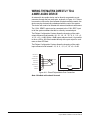
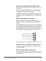
WIRING FOR ETHERNET CONNECTION
To connect the matrix to a local-area network (LAN), use the RJ-45
sockets labeled “LAN 1” and “LAN 2” on the rear of the Eclipse Omega
and Median matrices, or the RJ-45 socket labeled “LAN” on the rear of
the Eclipse Pico and Eclipse-32 matrices. The connectors have
standard Ethernet pin assignments, shown in Figure 4-3.
PIN
1
2
3
4
5
6
7
8
FUNCTION
Transmit data +
Transmit data
Receive data +
LAN1 and LAN2
Ethernet RJ-45 Connectors
8 765 4 321
Unused
Unused
Receive data
Unused
Unused
Figure 4-3: Pin Assignments for LAN 1 and LAN 2 Connectors
Note: Shielded CAT-5 cable should be used.
Clear-Com Communication Systems
Eclipse Matrix Installation Instruction Manual
4-7
CONNECTING MATRICES WITH
FIBER-OPTIC CABLE
Each fiber card link consists of a front card with various status
indicators and a rear card with two Duplex LC Terminated fiber optic
connectors (TXVRA and TXVRB). The fiber cards use 9/125µ Single
Mode fiber optic cables. On the rear card the TX1/RX1 connector is
used for the main ring and the TX2/RX2 connector is used for the
secondary ring. Single mode 9/125µ fiber optic cable should be used
for connections and the matrices should be wired up with the system
with the lowest I/P address being system 1.
The standard maximum node length is 10km but other distances are
available to special order.
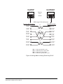
The order of the fiber optic cable connections is reversed between the
front and rear panels. On the front panel the primary connection is the
upper set of indicators but on the rear panel it is the lower connector.
Similarly the secondary connection is the lower set of indicators on the
front panel but the upper connector on the rear panel. Care should be
taken when connecting or disconnecting the cables to ensure that they
are connected correctly and not reversed.
Normally a protective plug is fitted to the fiber connector sockets to
protect them from damage or the entry of foreign materials. These
should only be removed in order to fit the fiber optic cable and replaced
if the cable is unplugged.
WIRING THE MATRIX TO INTERCOM
PANELS
Eclipse uses a 4-pair (analog) or single-pair (digital) wiring scheme
between the frame and panels. All Eclipse panels have built-in RJ-45
connectors.
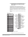
4-PAIR ANALOG
Four-pair analog wiring is done with shielded CAT5 RJ-45 cable.
• Pair 1 transmits analog audio from the matrix to the panel.
• Pair 2 transmits digital data from the panel back to the matrix.
• Pair 3 transmits audio from the panel to the matrix.
• Pair 4 transmits digital data from the matrix back to the panel.
4-8
Clear-Com Communication Systems
Eclipse Matrix Installation Instruction Manual
RJ-45 CONNECTOR
AT MATRIX PORT
RJ-45 CONNECTOR ON
PANEL OR INTERFACE
8 765 4 321
Views from
front of
connectors
8 765 4 321
Shielded category-5 cables wired pin-to-pin
Matrix Frame RJ-45 Pin Numbers
RS-422 Input +
(into Matrix)
1
RS-422 Input –
(into Matrix)
2
Audio Input +
(into Matrix)
3
Audio Output +
(from Matrix)
4
Audio Output –
(from Matrix)
5
Audio Input –
(into Matrix)
6
RS-422 Output +
(from Matrix)
7
RS-422 Output –
(from Matrix)
8
Panel RJ-45 Pin Numbers
Pair 2
Pair 1
Pair 3
Pair 4
Pair
Pair
Pair
Pair
1
2
3
4
1
RS-422 Output +
(from panel)
2
RS-422 Output –
(from panel)
3
Audio Output +
(from panel)
4
Audio Input +
(into panel)
5
Audio Input –
(into panel)
6
Audio Output –
(from panel)
7
RS-422 Input +
(into panel)
8
RS-422 Input –
(into panel)
Audio output from Matrix to panel
RS-422 data input from panel to Matrix
Audio input from panel to Matrix
RS-422 data output from Matrix to panel
Figure 4-4: Wiring Matrix to Analog Panel Using RJ-45
Clear-Com Communication Systems
Eclipse Matrix Installation Instruction Manual
4-9
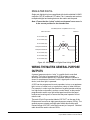
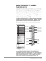
SINGLE-PAIR DIGITAL
Single-pair digital wiring is accomplished with double-shielded 24 AWG
conductor CAT-6E enhanced STP cable. Pair 1 transmits and receives
multiplexed digital and analog between the matrix and the panel.
Note: Ensure that the “select” switch on the panel’s rear cover is
in the correct position for the intended use.
ATT-T568B (Modular Jumpers
Wired One to One)
Panel End
Matrix Frame End
Pair 2
No Connection (NC)
1
No Connection (NC)
2
No Connection (NC)
3
Multiplexed Data/Audio
4
Multiplexed Data/Audio
5
No Connection (NC)
6
No Connection (NC)
7
No Connection (NC)
8
1
2
Pair 1
3
4
Pair 3
5
6
Pair 4
7
8
Figure 4-5: Wiring Matrix to Digital Panel Using RJ-45
WIRING THE MATRIX GENERAL-PURPOSE
OUTPUTS
A general purpose output or “relay” is a switch that is controlled
remotely. The relay is programmed in ECS to close a contact
whenever an intercom panel’s key is pressed. When the contact is
closed, it completes an electronic circuit’s signal path so that a remote
device, such as a light, is powered.
A GPO can be programmed to mute a speaker, to turn on an applause
light, to turn on a door lock, or to perform a variety of other functions.
For example, in order to get the attention of a panel operator working
in a high-noise environment, such as a control booth, a relay can be
programmed to switch on a light at that panel each time the panel
receives an incoming call, to ensure that the panel operator will not
miss the call.
The male 25-pin D-type socket labeled “GP OUT” on the rear of the
Eclipse matrix connects to eight general-purpose outputs (GPOs). The
general purpose outputs are single-pole double-throw relays with
contact ratings of 30 VDC (volts direct current) at 1 ampere. Shielded
cable should be used to connect GPOs.
4-10
Clear-Com Communication Systems
Eclipse Matrix Installation Instruction Manual
Note: If the GP-OUT port is used the following filter must be fitted
between the PROC-RCC socket and the cable: CINCH
FA-25PS/1 25W D-type in-line 1000pF filter (UK supplier:
Farnell 111-4108).
Each general-purpose output has a relay inside the Eclipse
Omega/Median frame. When a general-purpose output is inactive, the
associated “common” pin on the GP OUT connector will be shorted to
the relevant “normally closed” pin. When a general-purpose output
becomes active, the short between the “common” pin is broken and a
new connection is made between the “common” pin and the “normally
open” pin.
Figure 4-6 shows the pin configuration of the general-purpose outputs
connector.
DB-25 Male Connector
PIN
1
2
3
4
5
6
7
8
9
10
11
12
13
14
15
16
17
18
19
20
21
22
23
24
25
DESCRIPTION
RELAY
RELAY
RELAY
RELAY
1
1
1
2
Common
Normally Closed
Normally Open
Common
RELAY 2 Normally Closed
RELAY 2 Normally Open
RELAY 3 Common
RELAY 3 Normally Closed
RELAY 3 Normally Open
RELAY 4 Common
RELAY 4 Normally Closed
RELAY 4 Normally Open
GROUND
RELAY 5 Common
RELAY 5 Normally Closed
RELAY 5 Normally Open
RELAY 6 Common
RELAY 6 Normally Closed
RELAY 6 Normally Open
RELAY 7 Common
RELAY 7 Normally Closed
RELAY 7 Normally Open
RELAY 8 Common
RELAY 8 Normally Closed
RELAY 8 Normally Open
Common
RELAY 1
Normally Closed
Normally Open
Common
RELAY 2
Normally Closed
Normally Open
1
14
2
15
3
16
4
17
5
18
6
19
Common
RELAY 3
Normally Closed
Normally Open
Common
RELAY 4
Normally Closed
Normally Open
7
20
8
21
9
22
10
23
11
24
12
25
Digital Ground
Common
Normally Closed
RELAY 5
Normally Open
Common
Normally Closed
RELAY 6
Normally Open
Common
Normally Closed
RELAY 7
Normally Open
Common
Normally Closed
RELAY 8
Normally Open
13
30 VDC at 1 Ampere
Figure 4-6: General-Purpose Outputs Connector Pinout
Clear-Com Communication Systems
Eclipse Matrix Installation Instruction Manual
4-11
WIRING THE MATRIX TO GENERAL
PURPOSE INPUTS
It is possible to connect an external logic device such as an external
foot switch, a panel-mounted switch, or the logic output of some other
device to the connector labeled “GP IN” on the rear of the Eclipse
matrix. When the external logic device is activated, it sends a control
signal into the matrix to perform one of several preset functions, such
as turning an intercom panel’s microphone on or off, muting a
microphone’s output, or turning a panel’s speaker off. The function to
perform and the panel upon which it is performed is configured using
the Eclipse Configuration System (ECS).
The DB-25 connector labeled “GP IN” on the rear of the Eclipse matrix
connects to eight local general-purpose inputs. Figure 4-7 shows the
pin assignments of the Eclipse general-purpose inputs connector.
Shielded cable should be used to connect General Purpose Inputs.
DB-25 Female Connector
PIN
1
2
3
4
5
6
7
8
9
10
11
12
13
14
15
16
17
18
19
20
21
22
23
24
25
DESCRIPTION
Logic Input 1
Logic Input 2
Logic Input 3
Logic Input 4
N/A
N/A
N/A
N/A
Ground
Ground
Ground
Ground
Ground
Logic Input 5
Logic Input 6
Logic Input 7
Logic Input 8
N/A
N/A
N/A
N/A
Voltage In+
Voltage In+
Voltage InVoltage In-
Logic Input 1
1
Logic Input 2
2
Logic Input 3
3
Logic Input 4
4
14
Logic Input 5
15
Logic Input 6
16
Logic Input 7
17
Logic Input 8
5
18
6
19
7
20
8
21
Ground
9
Ground
10
Ground
11
Ground
12
Ground
13
22
V IN+
23
V IN+
24
V IN–
25
V IN–
Figure 4-7: General-Purpose Inputs Connector Pinout
The general-purpose inputs operate in one of two modes: the
“opto-isolated” mode or the unisolated mode. The opto-isolated mode
requires the externally connected equipment to provide the current to
power the general-purpose input. The non-isolated mode does not
require that the externally connected equipment powers the
4-12
Clear-Com Communication Systems
Eclipse Matrix Installation Instruction Manual
general-purpose input. A voltage output on the GP IN connector
supplies the current.
To select a mode, move the J1 jumper on the CPU rear card to one of
two positions. (The J1 jumper is located on the inner-frame side of the
DB-25 connector.)
• For opto-isolated mode, fit the J1 jumper across pins 1 and 2.
• For non-isolated mode, fit the J1 jumper across pins 2 and 3.
Note: It is recommended that the connector is set to the fully
opto-isolated mode.
OPTO-ISOLATED MODE
Figure 4-8 shows the opto-isolated connection.
U
EXTVIN+
7-24V
8
+
C
10uF_25V
D
BYG22D
VIN
VOUT
LM78L05ACM
1
+3V3
+
+3V3
R
33K2
C
10uF_10V
R
33K2
U
R29 1.5K
EXTVIN-
1
8
EXTERNAL INPUT 1
2
7
3
6
4
5
R30
EXTERNAL INPUT 2
INPUT 1
INPUT 2
1.5K
MOCD207-M
Figure 4-8: Opto-Isolated Connection to Eclipse GPI Connector
In this mode, a DC voltage of between 7 and 24 volts is required at the
EXTVIN+ pin with relation to the EXTVIN– pin. To cause an input to
detect an active signal, current must flow from the relevant input pin.
The external device should draw no current to cause an inactive input
and at least 5 mA to cause an active input. The opto-isolator drive line
contains a 1.5 kOhm resistor to limit the current through the
opto-isolator. Therefore the input pins can be connected directly to the
EXTVIN– level to cause an active input.
The voltage level at the external input pin should not be allowed to go
below EXTVIN– or above +6 V with respect to EXTVIN–.
Clear-Com Communication Systems
Eclipse Matrix Installation Instruction Manual
4-13
NON-ISOLATED MODE
Figure 4-9 shows the non-isolated connection.
+3V3
+3V3
+3V3
R
33K2
R
33K2
U
R29 1.5K
EXTERNAL INPUT 1
R30
EXTERNAL INPUT 2
1
8
2
7
3
6
4
5
INPUT 1
INPUT 2
1.5K
MOCD207-M
Figure 4-9: Non-Isolated Connection to Eclipse GPI Connector
To cause an input to detect an active signal, current must flow from the
relevant input pin.
The external device should draw no current to cause an inactive input
and at least 5 mA to cause an active input. The opto-isolator drive line
contains a 1.5 kOhm resistor to limit the current through the
opto-isolator. Therefore the input pins can be connected directly to a
ground pin to cause an active input.
The voltage level at the external input pin should not be allowed to go
below ground or above +6 with respect to ground.
4-14
Clear-Com Communication Systems
Eclipse Matrix Installation Instruction Manual
WIRING THE MATRIX TO AN EXTERNAL
ALARM
With the Alarm I/O DB-9F connector, an external alarm device can be
connected to monitor failures in the matrix. Pins are also available for
connecting an external alarm source to the matrix’s Alarm System. For
details on the functions that are monitored by the Alarm System refer
to the Eclipse Omega or Eclipse Median Manuals.
A failure will activate the relay contacts connected to pins 4, 5, and 9 of
the connector. These contacts are “dry”, and are rated at 1 A at 24
VDC. They are not recommended for AC mains line current.
Pins are provided for adding an additional alarm source to the matrix’s
alarm system. Pin 6 is an alarm input to the Eclipse matrix. It is
connected to the input of a 3.3 volt logic device. A logic high on this
input will cause the Eclipse matrix to detect an alarm condition. A logic
low or an open circuit will cause the Eclipse matrix to detect no alarm
condition.
Pin 1 is a voltage source out of the Eclipse matrix. It is connected
through a 10k ohm pull-up resistor to the +5 volt supply rail inside the
Eclipse matrix.
A contact closure placed across pins 1 and 6 will also cause an alarm
condition. The alarm outputs of the PSU-101 could be wired directly to
these pins allowing the CPU card to report PSU failures also.
Note: Shielded cable should be used.
System 200/COM-72
"Alarm I/O" DB-9F
Connector
1
6
2
PSU-101
"Alarm Relay"
Connector
1
To Alarm
2
To Alarm
3
7
4
3
8
4
Relay Normally Closed
9
5
Relay Wiper
Relay Normally Open
Figure 4-10: Alarm I/O Connector
Clear-Com Communication Systems
Eclipse Matrix Installation Instruction Manual
4-15
WIRING THE MATRIX DIRECTLY TO A
4-WIRE AUDIO DEVICE
An external 4-wire audio device can be directly connected to a port
connector through the four audio pins, as shown in Figure 4-11. If there
is excessive noise on the lines between this device and the matrix, the
device may be electronically unbalanced with the rest of the system.
The device will need to be isolated with external isolation transformers.
The “CALL SEND” output can be connected to the “CALL REC” input
to tell the system software that this is a directly connected port.
The Eclipse Configuration System allows the changing of the audio
output reference level between -24, -21, -18, -15, -12, -9, -6, -3, 0, +3,
+6, +9, +12, +14 dB. With a +12dB output reference level, it is possible
to drive a 200 to 400 Ohm headset directly with a port output for such
uses as direct IFB feed.
The Eclipse Configuration System allows the changing of the audio
input reference level between -12, -9, -6, -3, 0, +3, +6, +9, +11 dB.
Call Receive +
1
Call Receive -
2
Audio Receive +
3
Audio Send +
4
Audio Send -
5
Audio Receive -
6
Call Send +
7
Call Send -
8
1
2
3
4
5
6
7
8
Output
Input
Rear View of
Connector
Figure 4-11: Direct Eclipse Matrix Port Connection
Note: Shielded cable should be used.
4-16
Clear-Com Communication Systems
Eclipse Matrix Installation Instruction Manual
WIRING THE MATRIX TO INTERFACE
MODULES
Interface modules convert the 4-wire signals of a central matrix port to
some other form of communication, such as telephones, camera
intercoms, two-way radios, and so on. In this way, non-4-wire devices
can communicate with the central matrix.
Each interface module has hardware connectors to connect to both the
central matrix and to the external device that communicates with the
central matrix.
To house these interface modules, Clear-Com offers three types of
interface frames.
• The IMF-3 interface frame holds up to 11 interface modules in 3 RU
of rack space. Modular rear-mounted connector panels hold two
RJ-45 connectors to the matrix ports and two DB-9’s attaching the
connected devices. The frame uses an external PSU-101
rack-mounted power supply to supply power to the interface
modules. A second PSU-101 can be attached for redundancy.
Note: The IMF-3 frame has an individual rear panel for each
interface. All interfaces use the same rear panel, however
the use of the rear-panel connectors will vary with the type
of interface.
• The IMF-102 interface frame has slots for two interface modules in 1
RU of rack space. Its rear input/output connector panel has two
RJ-45 connectors and DB-9 connectors for each of the two interface
modules. It has an internal power supply and a connector for a
redundant power supply.
• The DIF-102 interface frame has slots for two digital DIG-2 interface
modules in 1 RU of rack space. DIG-2 interface modules allow the
matrix to connect to digital versions of Clear-Com intercom panels.
The DIF-102 frame is powered by one or two (for redundancy)
external AC mains to 24 VDC power supplies via locking DIN
connectors on the rear panel. All other voltages are derived directly
or indirectly from the 24 VDC on a DIG-2 interface module’s front and
rear cards.
CCI-22 and FOR-22 - The CCI-22 and FOR-22 dual audio interfaces
use each of the RJ-45 connectors on its rear panel for connection to
the matrix port. The top RJ-45 is for the first channel of the interface.
The lower RJ-45 is for the second channel. The DB-9Ms are the
interface’s audio and control inputs and outputs. Refer to the section
on those interfaces later in this chapter for wiring details.
AES-6 - The AES-6 digital interface rear cards provide coax or RJ-45
connectors for wiring to V-Series or 4000 Series II panels and RJ-45
connectors for wiring to the matrix. Refer to the AES-6 manual (part
no. 810365Z) for wiring details.
Clear-Com Communication Systems
Eclipse Matrix Installation Instruction Manual
4-17
DIG-2—The DIG-2 digital interface rear cards provide RJ-45
connections to ICS digital panels and Eclipse matrices. For wiring
details refer to the DIG-2/DIF-102 manual (part. no. 810311Z).
TEL-14—The TEL-14 interface is a two-channel device and uses each
of the RJ-45 connectors on its rear panel for connection to the matrix
port. The top RJ-45 is for Line A of the interface and the lower RJ-45 is
for Line B of the interface. The upper and lower DB-9M connectors are
the Line A and Line B connections to the telephone line. Clear-Com
provides DB-9F to RJ-11 adapters so that standard phone line RJ-11
plugs and jacks can connect directly to the interface. Refer to the
section on this interface later in this chapter for wiring details.
Each audio interface has internal ID circuit jumpers that will identify to
the matrix port cards the type of interface it is; as a result the ports and
interface modules can be moved without having to change the wiring.
RLY-6 and GPI-6—The RLY-6 and GPI-6 use the same RJ-45s,
however their function and connection is different. These interfaces
are daisy chained in their direct connection to the matrix frame. RLYs
and GPIs do not require connection to a system “port.” The first RLY or
GPI interface has its RJ-45 connected to the special RJ-45 on the rear
panel of the frame marked GPI/RLY Interface. The top connector of the
second RLY or GPI interface connects to the bottom RJ-45 of the first.
Each successive interface is connected in this daisy-chained fashion.
Note: For Eclipse systems if both GPI-6 and RLY-6 interfaces are
used the GPI-6 interfaces must be placed first in the daisy
chain.
This restriction does not apply to Matrix Plus 3 systems where
interfaces can be mixed in this 'daisy-chained' scheme.
The maximum combined length of all the RJ-45 cables should not
exceed 20 feet (6 meters). Figure 4-12 shows an example of
“daisy-chain” wiring.
Figure 4-12 shows the rear panel of a IMF-3 wired for RLY-6s and
GPI-6s. The CPU card will read these modules and will call the first
RLY-6 relays 1 to 6. The second RLY-6 will be identified as relays 7 to
12.
4-18
Clear-Com Communication Systems
Eclipse Matrix Installation Instruction Manual
Ports
Rear View of IMF-3 Frame
GPI/RLY
Interface
Connector
RJ-45
RJ-45
RJ-45
RJ-45
RJ-45
DB-9
DB-9
DB-9
DB-9
DB-9
RJ-45
RJ-45
RJ-45
RJ-45
RJ-45
DB-9
DB-9
DB-9
DB-9
DB-9
Other
Interfaces
RLY-6
#2
RLY-6
#1
GPI-6
#2
GPI-6
#1
Figure 4-12: RLY-6/GPI-6 Daisy Chain Connection
Figure 4-13 shows the pin assignments of RJ-45 connectors when
used to connect to interfaces (IMF-3 frames).
Interface Wiring
Matrix Frame End
Interface End
Pair 2
Call Receive +
1
Call Receive -
2
Audio Receive +
3
Audio Send +
4
Audio Send -
5
Audio Receive -
6
Call Send +
7
Call Send -
8
Pair 1
Pair 3
Pair 4
1
Call Send +
2
Call Send -
3
Audio Send +
4
Audio Receive +
5
Audio Receive -
6
Audio Send -
7
Call Receive +
8
Call Receive -
Figure 4-13: Matrix Frame to IMF-3 Interface Connection
Note: If the GPI/RLY port is used a ferrite must be added to the
socket end of the cable. A suitable ferrite is Würth
Electronik part: 74271132.
Note: Shielded cable should be used.
Clear-Com Communication Systems
Eclipse Matrix Installation Instruction Manual
4-19
FOR-22 4-WIRE/RADIO INTERFACE WIRING
The FOR-22 4-wire/radio interface connects two external 4-wire
circuits to the matrix. Camera intercoms, two-way radios, microwave
and satellite links, IFBs, and program audio in and out are candidates
for use with the FOR-22.
A FOR-22 interface connects to an Eclipse matrix through the two
RJ-45 connectors on the IMF-3 or IMF-102 rear panel assembly to
which the FOR-22 is connected. One RJ-45 connector is for the first
channel of the interface. The second RJ-45 connector is for the second
channel.
The user side of the FOR-22 for each channel appears on a DB-9M
connector on the rear of the IMF-3 for IMF-102 frame. Figure 4-14
shows the pinout of either one of these connectors. Each channel is
identical.
1
Audio Output
Audio Output
6
2
Audio Input
Audio Input
7
3
Logic Input (+/- 4 to 50 V)
Logic Input (+/- 4 to 50 V)
8
4
Relay Normally Closed
Relay Wiper
9
5
Relay Normally Open
Figure 4-14: Pinout of the DB-9M I/O Connectors for FOR-22s
The following sections describe how to wire for the various type of
inputs and outputs available on this connector:
• External audio devices
• Call signal input
• Relay contacts.
Note: Shielded cable should be used.
External Audio Devices
Connect external audio devices to the FOR-22 ports through the two
DB-9M connectors labeled “I/O” on the rear panel. Both audio input
and output are transformer isolated. For more information on the
4-20
Clear-Com Communication Systems
Eclipse Matrix Installation Instruction Manual
various level ranges available on the input and output refer to the
FOR-22 manual (part 810306Z).
Call Signal Input
The Call Signal input is used to receive a call/logic input signal from an
external device and send it to the matrix. The voltage across the pins
required to receive a call signal ranges from 4 to 50V; it can be either
positive or negative polarity or AC. The input will draw between 4 and 8
mA.
Relay Contacts
Each FOR-22 interface channel features a relay that is associated with
the logical call signal output of a port. A relay’s function depends on
the function assigned to the FOR-22 port through the Eclipse
Configuration System program. A relay can be assigned to operate
with any label in the system: when that label is activated (either by a
talk, listen, or both, as set from the configuration program), the relay
will activate. For details on configuring the use of a relay, see the
Eclipse Configuration System Manual (part 810299Z).
The relay can be used to activate an external device, such as an
applause light in a studio, a cue light, or a security-door lock. The
relays feature both “normally open” and “normally closed” contacts.
The contacts are rated at 1 A at 24 VDC; they are not designed for
switching mains AC line voltage.
CCI-22 PARTY-LINE INTERFACE WIRING
The CCI-22 party-line interface connects two 2-wire full-duplex
party-line circuits to the matrix. This interface has its own manual in the
Eclipse manual set. The following discussion gives an overview of the
wiring of this interface.
The CCI-22 interface uses each of the RJ-45 connectors on its rear
panel for connection to the matrix port. One RJ-45 connector is for the
first channel of the interface. The second RJ-45 connector is for the
second channel.
The user side of the CCI-22 for each channel appears on a pair of
DB-9M connectors on the rear of the interface. Figure 4-15 shows the
pinout of either one of these connectors. Both DB-9s are paralleled
such that both party-line channels are available on each connector. It
is possible to wire one DB-9 connector as channel #1 and the second
DB-9 as channel #2 or bring both channels out either DB connector
together to create a TW-type, party-line connection. Refer to the
CCI-22 Interface Instruction Manual (part 810307Z) for more
information.
Clear-Com Communication Systems
Eclipse Matrix Installation Instruction Manual
4-21
Channel 1
Channel 2
CC/RTS
6
Ground
7
+30 VDC Power
8
Audio
9
1
CC/RTS
2
Ground
3
+30 VDC Power
4
Audio
5
Figure 4-15: Pinout of the DB-9M Interface I/O Connectors for CCI-22
Clear-Com Party Lines General Discussion
Stations on Clear-Com party lines connect to each other with
two-conductor shielded microphone cable. One conductor carries the
DC power (28 to 30 V) for that channel, while the other conductor
carries the duplex two-way intercom audio signal plus DC “Call Light”
signaling for that channel. The shield acts as common ground for both
power and signal for the channel.
Power to the CCI-22 interface channels must be provided by the
external party line. The power connection for each channel is the “+30
VDC Power” pin on the appropriate DB-9M interface I/O connector on
the rear-panel assembly. The CCI-22 channel is essentially just
another “beltpack” on the party line.
The power pin has DC filtering circuitry that provides a high impedance
for the audio such that power can be received from a “powered line or
TW line” as is common with RTS systems. For TW operation tie the
AUDIO and POWER pins together.
Each party-line channel requires exactly one termination circuit. The
termination circuit is usually built into the system component that
provides the party line’s power. Connecting more than one termination
circuit to a party line will impair the sidetone null and degrade the line’s
audio quality.
When a CCI-22 party-line channel is connected to a Clear-Com party
line, the Clear-Com/RTS “select” pin must be left floating. Grounding
this pin selects the RTS mode, which is incompatible with Clear-Com
party lines.
TEL-14 TELEPHONE INTERFACE WIRING
The TEL-14 telephone interface connects two telephone lines to the
matrix. The interface can establish IFB connections between the main
intercom and remote production trucks, can link intercom
communication between remote systems, and can enable telephone
4-22
Clear-Com Communication Systems
Eclipse Matrix Installation Instruction Manual
calls directly to or from any intercom panel in an Eclipse or other
system. The TEL-14 interface has its own manual in the Eclipse
manual set. This following discussion gives an overview of the wiring
of this interface.
The TEL-14 uses each of the RJ-45 connectors on its rear panel for
connection to a matrix port. One RJ-45 is for Line A of the interface
and the other RJ-45 is for Line B of the interface.
The DB-9M connectors are the Line A and Line B connections to the
telephone line. Clear-Com provides DB-9F to RJ-11 adapters so that
standard phone line RJ-11 plugs and jacks can connect directly to the
interface.
IMF-3 Interface Module Frame Wiring
On the rear of the IMF-3 frame, there is a separate rear-panel
assembly for each interface, which contains four connectors for each
interface. The following instructions refer to any single rear-panel
assembly.
The upper DB-9M connector is used to connect to the first telephone
line, A. The upper RJ-45 connector is used to connect telephone line A
to the matrix frame. The lower DB-9M connector is used to connect to
the second telephone line, B. The lower RJ-45 connector is used to
connect telephone line B to the matrix frame. Figure 4-16 illustrates the
wiring of one IMF-3 rear-panel assembly to a TEL-14 interface.
Connects telephone line A to matrix.
CH. A
Matrix
Connects to the first telephone line, A.
CH. A
I/O
PHONE
LINE A
Connects telephone line B to matrix.
CH. B
Matrix
Connects to second telephone line, B.
CH. B
I/O
PHONE
LINE B
Figure 4-16: Wiring an IMF-3 Rear-Panel Assembly to a TEL-14 Interface
To allow use of a common RJ-11 terminated telephone line, Clear-Com
provides two DB-9F to RJ-11 adapters (Clear-Com part 770025).
For internal dip-switch settings and adjustments, refer to the TEL-14
manual (part 810308Z).
IMF-102 Interface Module Frame Wiring
On the rear of the IMF-102 frame, there are two sets of four connectors
each, arranged horizontally. The following instructions refer to either
one of the two sets.
Clear-Com Communication Systems
Eclipse Matrix Installation Instruction Manual
4-23
The leftmost DB-9M connector is used to connect to the first telephone
line, A. The leftmost RJ-45 connector is used to connect telephone line
A to the matrix frame. The rightmost DB-9M connector is used to
connect to the second telephone line, B. The rightmost RJ-45
connector is used to connect the telephone line B to the matrix. Figure
4-17 illustrates the wiring of one IMF-102 rear-panel assembly to a
TEL-14 interface.
Connects to the first telephone line, A.
Connects telephone line A to the matrix.
CH.A
I/O
CH.A
Matrix
CH.B
I/O
CH.B
Matrix
CH.A
I/O
CH.A
Marix
CH.B
I/O
CH.B
Matrix
Connects telephone line B to the matrix.
Connects to the second telephone line, B.
Figure 4-17: Wiring an IMF-102 Rear-Panel Assembly to a TEL-14
Interface
To allow use of a common RJ-11 terminated telephone line, Clear-Com
provides two DB-9F to RJ-11 adapters (part 770025).
For internal dip-switch settings and adjustments, refer to the TEL-14
manual (part 810308Z).
Connecting to the Telephone Line
Connecting the telephone line can be accomplished with one of two
methods. One method is to use the RJ-11 to DB-9F adapters supplied
by Clear-Com with the TEL-14 interface. The second method is to
directly wire each telephone line to a DB-9F connector using the
pinouts in Figure 4-18, which shows the wiring diagram of the adapter.
4-24
Clear-Com Communication Systems
Eclipse Matrix Installation Instruction Manual
DB-9 to TEL-14
Line
1
6
Phone
Line
2
7
Relay
3
8
Relay
RJ-11
to Telephone
Line
RJ-11 to DB-9F Adapter
Clear-Com Part Number 770025
1
Phone (Blue
2
Relay (Yellow)
3
Line (Gray)
4
Line (Red)
5
Relay (Black)
6
Phone (Gray)
4
9
Phone
5
Figure 4-18: RJ-11 to DB-9 Adaptor for TEL-14 Interfaces
Note: The TEL-14 interface works with telephone company central
office (CO) lines. Analog panel lines from some in-house
PABXs are not compatible.
Telephone Set
Although it is possible to use a parallel-connected telephone set to
originate calls, it is preferable to use a series-connected telephone set
with the TEL-14. This will prevent the impedance of the telephone set
from disturbing the telephone line impedance recognized by the
TEL-14. It will also allow the TEL-14 to automatically disconnect the
telephone when it comes “off-hook.” A standard telephone may be
installed in series with the TEL-14 by connecting it to pins 1 and 6 of
the RJ-11 jack. If telephones must be connected in parallel with the
telephone line(s) during the TEL-14’s automatic nulling process, all
additional standard telephones must be “on-hook”.
Relay Contacts
A pair of relay contacts for each telephone line rated at 2A at 24 VAC is
available on the DB-9 or the RJ-11 of the adapter. This pair of contacts
is normally open when the line is “on-hook,” and closes when the
interface goes “off-hook”. These contacts are not connected to any
other circuitry inside the interface, and can be used to energize a
line-in-use indicator light on a standard multiline phone set, or for any
other low-power application.
RLY-6 INTERFACE WIRING
The RLY-6 relay interface module provides connection of six
programmable relays to the matrix so that each relay is directly
controlled from the matrix. Multiple RLY-6 interfaces can be daisy
chained to provide connection of up to 60 relays to the matrix. RLY-6
Clear-Com Communication Systems
Eclipse Matrix Installation Instruction Manual
4-25
and GPI-6 modules can be mixed together up to the total limit of 60
items. Five RLY-6 and five GPI-6 modules would provide 30 relays and
30 inputs for a total of 60 inputs and outputs.
Note: For Eclipse systems if both GPI-6 and RLY-6 interfaces are
used the GPI-6 interfaces must be placed first in the daisy
chain.
This restriction does not apply to Matrix Plus 3 systems where
interfaces can be mixed in this 'daisy-chained' scheme.
The RLY-6 interface has its own manual in the Eclipse manual set (part
810310Z). This discussion gives an overview of the wiring of this
interface.
IMF-3 Interface Module Frame Wiring
To Matrix Frame
To connect the RLY-6 to the matrix frame, plug one end of an RJ-45
cable (eight wires with no reversal) into the GPI/RLY INTERFACE
connector on the back of the matrix. Plug the other end into the top
RJ-45 (CH. A MATRIX) connector for the RLY-6.
To connect an additional RLY-6 interface, plug one end of a short
RJ-45 cable into the lower RJ-45 (CH. B MATRIX) for the first RLY-6.
Then, plug the other end into the top RJ-45 (CH. A MATRIX) connector
for the additional RLY-6. Additional RLY-6 Interfaces are added in the
same way, using daisy-chain wiring. If there are multiple RLY-6
modules, the relays in the first will be numbered 1 to 6, second will be
7 to 12, etc. GPI-6 modules can be mixed in this daisy-chained
scheme. The maximum combined length of all the RJ-45 cables should
not exceed 20 ft. (6 m). Refer to Figure 4-19.
Note: For Eclipse systems if both GPI-6 and RLY-6 interfaces are
used the GPI-6 interfaces must be placed first in the daisy
chain.
This restriction does not apply to Matrix Plus 3 systems where
interfaces can be mixed in this 'daisy-chained' scheme.
4-26
Clear-Com Communication Systems
Eclipse Matrix Installation Instruction Manual
Ports
Rear View of IMF-3 Frame
GPI/RLY
Interface
Connector
RJ-45
RJ-45
RJ-45
RJ-45
RJ-45
DB-9
DB-9
DB-9
DB-9
DB-9
RJ-45
RJ-45
RJ-45
RJ-45
RJ-45
DB-9
DB-9
DB-9
DB-9
DB-9
Other
Interfaces
RLY-6
#2
RLY-6
#1
GPI-6
#2
GPI-6
#1
Figure 4-19: Rear View of IMF-3 Frame
To External Device
To connect external devices to an RLY-6 interface, use the two DB-9M
connectors on the rear cable assembly panel for the interface. Figure
4-20 shows the pin assignment of these connectors as viewed from
the frame side of the connector.
If a DB-9F is plugged into the connector labeled CH. A I/O, relays 1 to
3 are available on that connector. The connector labeled CH. B I/O has
the contacts for relays 4 to 6. In Figure 4-20, the labels on the pins
apply to either connector. Example: #1/4 COM refers to the wiper of
relay 1 if it is connected to CH. A and the wiper of relay 4 if it is
connected to CH. B.
Clear-Com Communication Systems
Eclipse Matrix Installation Instruction Manual
4-27
1
6
#1/4 Normally Closed
#1/4 COM
2
#1/4 Normally Open
#2/5 Normally Closed
7
3
8
#2/5 COM
#2/5 Normally Open
4
9
#3/6 Normally Closed
#3/6 COM
5
#3/6 Normally Open
Figure 4-20: RLY-6 Interface DB-9M Connector Pinout
IMF-102 Interface Module Frame Wiring
The wiring of an RLY-6 interface that is placed in an IMF-102 interface
frame is the same as the wiring for a RLY-6 interface placed in an
IMF-3 interface frame. The only difference is that an IMF-102 interface
frame houses only two interfaces, and they are mounted horizontally
rather than vertically in the frame. Figure 2-1 and Figure 2-2 in
Chapter 2 illustrate the differences between these interface frames.
Refer to the respective manuals for these interfaces and frames in the
Eclipse manual set for more information.
Configuration
To associate a relay to a label, use the Eclipse Configuration System,
as described in its manual.
4-28
Clear-Com Communication Systems
Eclipse Matrix Installation Instruction Manual
GPI-6 INTERFACE WIRING
The GPI-6 input interface module provides connection of six
programmable inputs to the matrix so that each input can control a
predefined matrix function. Multiple GPI-6 interfaces can be
daisy-chained to provide connection of up to 60 inputs to the matrix.
RLY-6 and GPI-6 modules can be mixed together up to the total limit of
60 items. Five RLY-6 and five GPI-6 modules would provide 30 relays
and 30 inputs for a total of 60 inputs and outputs.
Note: For Eclipse systems if both GPI-6 and RLY-6 interfaces are
used the GPI-6 interfaces must be placed first in the daisy
chain.
This restriction does not apply to Matrix Plus 3 systems where
interfaces can be mixed in this 'daisy-chained' scheme.
IMF-3 Interface Module Frame Wiring
To Matrix Frame
To connect the GPI-6 to the matrix frame, plug one end of an RJ-45
cable (eight wires with no reversal) into the GPI/RLY INTERFACE
connector on the back of the frame. Plug the other end into the top
RJ-45 (CH. A MATRIX) connector for the GPI-6.
To connect an additional GPI-6 Interface, plug one end of a short
RJ-45 cable into the lower RJ-45 (CH. B MATRIX) for the first GPI-6.
Then, plug the other end into the top RJ-45 (CH. A MATRIX) connector
for the additional GPI-6. Additional GPI-6 Interfaces are added in the
same way, using daisy-chain wiring. If there are multiple GPI-6s used,
the inputs in the first will be numbered 1 to 6, second will be 7 to 12,
etc. RLY-6 modules can be mixed in this daisy-chained scheme. The
maximum combined length of all the RJ-45 cables should not exceed
20 ft. (6 m). Refer to Figure 4-19 on page 1-27.
To External Device
To connect external devices to the GPI-6 interface, use the two DB-9M
connectors on the rear cable assembly panel for the interface. Figure
4-21 shows the pin assignment of these connectors as viewed from
the frame side of the connector.
If a DB-9F is plugged into the connector labeled CH. A I/O, inputs 1 to
3 are available on that connector. The connector labeled CH. B I/O has
inputs 4 to 6. In Figure 4-21, the labels on the pins apply to either
connector.
Clear-Com Communication Systems
Eclipse Matrix Installation Instruction Manual
4-29
GPI-6 I/O DB 9M
1
#1/4 Input A
6
#1/4 Input B
#2/5 Input A
2
#2/5 Input B
7
3
#3/6 Input A
8
#3/6 Input B
Ground
4
9
Power Source
Ground
5
Figure 4-21: GPI-6 Interface DB-9M Connector Pinout
GPI-6 I/O DB-9M
GPI-6 I/O DB-9M
1
1
6
6
2
2
7
7
3
3
8
8
4
9
X
4
5
X
X
9
5
X
Figure 4-22: GPI-6 Application Examples
Figure 4-21 and Figure 4-22 show how to connect switches or contacts
using the power source provided by the GPI-6 module or powering
switches from external sources. Each input can be wired to be isolated
from each other as a further variation.
IMF-102 Interface Module Frame Wiring
The wiring of a GPI-6 interface that is placed in an IMF-102 interface
frame is the same as the wiring for a GPI-6 interface placed in an
IMF-3 interface frame. The only difference is that an IMF-102 interface
frame houses only two interfaces, and they are mounted horizontally
rather than vertically in the frame.
Figure 2-1 and Figure 2-2 in Chapter 2 illustrate the differences
between these interface frames.
4-30
Clear-Com Communication Systems
Eclipse Matrix Installation Instruction Manual
Refer to the respective manuals for these interfaces and frames in the
Eclipse manual set for more information.
Configuration
To define an input function, use the Eclipse Configuration System
program, as described in its manual.
Clear-Com Communication Systems
Eclipse Matrix Installation Instruction Manual
4-31
WIRING AN ICS PANEL MISCELLANEOUS
CONNECTOR
Most local devices connect with a matrix panel via the “miscellaneous”
connector.
The following sections discuss how to wire the various functions
available on the “miscellaneous” connector.
• External program feed input
• Binaural headset (All Panels Except ICS-2003/2110/1016)
• Logic input #1 and logic input #2
• Mute relay contacts
• Auxiliary relay contacts.
1
+ Program Input
9
2
Audio Ground
10
3
Second Ear Ground (Audio Ground in ICS-2003/ICS-2110)
Second Ear Output (Audio Ground in ICS-2003/ICS-2110)
11
4
Logic Ground
Logic Ground
12
5
Logic Input #2
Logic Input #1
13
Mute Relay Normally Closed
14
Mute Relay Wipe
6
Station Relay Normally Closed
7
Station Relay Wipe
15
8
- Program Input
Mute Relay Normally Open
Station Relay Normally Open
Figure 4-23: Miscellaneous Connector Pin Configuration
EXTERNAL PROGRAM FEED INPUT
The external program feed input allows the panel operator to monitor
audio from an external source while simultaneously monitoring the
intercom audio.
The input is designed to accept a balanced, line-level audio feed at a
maximum level of 0 dB. On some panels there is no “program” volume
control. This is just a summing input to the “listen” amplifier.
The program feed input passes through the panel’s “program” volume
control before being mixed with the audio at the panel. The “program”
4-32
Clear-Com Communication Systems
Eclipse Matrix Installation Instruction Manual
feed (“program audio”) can be heard on the panel’s speaker and
headset; it cannot be heard by other panels in the matrix.
To connect an external program feed to the panel, connect the
balanced audio pair to pins 1 and 9, and connect a shield or ground
connection if available to pin 2 of the connector (refer to Figure 4-23).
BINAURAL HEADSET (ALL PANELS EXCEPT
ICS-2003/2110/1016)
The second ear output allows an external binaural headset to be
connected to the panel. One side of the binaural headset is connected
to the panel’s audio feed from the matrix frame; this is “intercom
audio,” and its volume level is controlled by the “intercom” knob on the
front panel. The other side of the binaural headset is connected to the
panel’s external program feed input; this is “program audio,” and its
volume level is controlled by the “program” knob on the front panel.
For more information on implementing this feature, refer to the Eclipse
Configuration System Instruction Manual (part 810299Z).
ICS-2003 LOGIC INPUT #1 AND LOGIC INPUT #2
This section describes how to connect to the logic inputs of the panel
and briefly discusses the functions that can be implemented.
The functions that are available are listed below. For a more detailed
description and instructions on how to implement them with the Eclipse
Configuration System, refer to the ICS-2003 Intercom Panel Instruction
Manual (part 810303Z).
• Mic on/off (toggle)
• Mute microphone output to frame
• Microphone off (momentary)
• Answerback talk/clear
• Speaker off
• PTT: activate all talks
• Activate talk switch #1
• Activate talk switch #2
• Activate listen labels button
• Studio announce
• PTT: activate two-way radio talks.
Logic Input #1 supports only active low inputs (0 to 2 VDC with
reference to ground), while Logic Input #2 can support either active
high (4 to 30 VDC) or active low inputs, depending on whether a
jumper has been installed at JP2 (active low is the default with no
jumper installed). Refer to the ICS-2003 chapter of this manual for
Clear-Com Communication Systems
Eclipse Matrix Installation Instruction Manual
4-33
details on setting this jumper. The ICS-2003 only supports an active
low input on both inputs.
Use normally open type switches to activate the logic inputs. Connect
the switches as follows (refer to Figure 4-23):
• Logic Input #1—pins 4 to 5 (pin 4 = ground)
• Logic Input #2—Pins 11 to 12 (pin 11 = ground)
Do not apply external voltage to the logic inputs, except in the case of
Logic Input #2 being configured for an active high input as described
above.
MUTE RELAY CONTACTS
This set of relay contacts will be activated whenever any talk path is
activated at the panel. The contacts can be used to activate an
external device when a talk path is active, for example, for muting a
control room monitor speaker. Refer to Figure 4-23 for wiring details.
Both “normally open” and “normally closed” contacts are provided.
They are rated at 1 A at 24 VDC. This relay is not designed for
switching mains AC line voltage. To switch an external device that runs
on mains AC line voltage, use an external relay (or other switching
mechanism) that is activated by this relay.
AUXILIARY RELAY CONTACTS
Each Eclipse system panel includes a relay that is controlled by the
system program independent of the local panel function. This relay can
be assigned to any label(s) in the system, which will activate whenever
a talk or listen is set to that label(s). If activating the relay is the only
action desired, assign the relay to a “control” label. For more details
refer to the Eclipse Configuration System Instruction Manual Part
810299Z).
The relay can be used to activate an external device, such as an
applause light in a studio, a cue light, or a security door lock. Figure
4-23 on page 1-32 shows the wiring of the relay contacts to the
“miscellaneous” connector.
Both “normally open” and “normally closed” contacts are provided.
They are rated at 1 A at 24 VDC. This relay is not designed for
switching mains AC line voltage. To switch an external device that runs
on mains AC line voltage, use an external relay (or other switching
mechanism) that is activated by this relay.
4-34
Clear-Com Communication Systems
Eclipse Matrix Installation Instruction Manual
WIRING A BINAURAL HEADSET (ICS-2003)
The ICS-2003 has a second earphone output, but it functions and is
wired differently from all other ICS panels. This output is not available
on the “miscellaneous” connector, but on the main board of the panel
on a separate header connector. If a six pin headset connector were
installed on the front or rear of the panel, this output would be
available.
The default configuration of the panel has both earphone outputs being
fed with both intercom and program audio. To separate the “program”
input to the second ear only, use the Eclipse Configuration System.
Refer to the Eclipse Configuration System Instruction Manual (part
810299Z) for more information.
Figure 4-24 shows the wiring of a six pin XLR connector for a binaural
headset.
Front Panel Headset Connector
7
6
113
X
1
2
3
1
2
3
X
2
4
115
X
1
2
3
5
1
3
1
2
3
X
1
2
3
X
120
X
1
2
3
Figure 4-24: Binaural Headset Wiring
Clear-Com Communication Systems
Eclipse Matrix Installation Instruction Manual
4-35
WIRING AN ICS PANEL OPT-100 AUXILIARY
AUDIO I/O OPTION
Figure 4-25 shows the pinout of the DB-15F “auxiliary audio I/O”
connector on the back of the intercom panel. The sections that follow
the pinout diagram describe each function and how to wire for it.
"Auxiliary I/O" Connector DB-15F
1
+ SA Output
- SA Output
9
2
Audio Ground
Audio Ground
10
3
SA Relay Normally Open
4
SA Relay Wiper
11
Ground
Ground
12
5
SA Relay Normally Closed
- Aux Line Level Out
13
6
+ Aux Line Level Out
Ground
14
7
Ground
- Hot Microphone Out
15
8
+ Hot Microphone Out
Figure 4-25: Auxiliary I/O Connector
If installed, the OPT-100 Auxiliary Audio I/O Option provides three
additional audio output signals, plus a set of relay contacts. The
following functions are available:
• Auxiliary audio line level output
• “Hot mic” output
• SA (stage/ studio) announce output
• SA relay
4-36
Clear-Com Communication Systems
Eclipse Matrix Installation Instruction Manual
AUXILIARY AUDIO LINE LEVEL OUTPUT
The auxiliary audio line level output is a balanced line-level
transformer-isolated feed of the same audio signal that is sent to the
panel’s internal speaker. For example, this output could be used to
feed an external amplifier connected to a set of ceiling loudspeakers.
Connect to pins 6 and 13 for a balanced output. Pin 14 is available as
a shield or ground source. Refer to Figure 4-25.
HOT MIC OUTPUT
The “hot mic” output is a balanced line-level transformer-isolated feed
of the signal from the currently selected microphone (either the panel
microphone or the headset microphone).
The hot mic output is active regardless of whether the panel has talk
paths set, and regardless of the settings of the front panel controls on
the panel.
Connect to pins 8 and 15 for a balanced output. Pin 7 is available as a
shield or ground source. Refer to Figure 4-25.
SA (STUDIO/STAGE ANNOUNCE) OUTPUT
The SA output is a balanced line-level transformer-isolated feed of the
same signal sent to the hot mic output, except that it is only active
when the SA button on the panel’s front panel is pressed or when
activated by Logic Input #1 or #2 configured for the studio announce
function.
Connect to pins 1 and 9 for a balanced output. Pin 2 is available as a
shield or ground source (refer to Figure 4-25).
SA RELAY
The SA relay is activated whenever the SA button on the front panel of
the panel is pressed or when activated by Logic Input #1 or #2
configured for the Studio Announce Function. Both “normally open”
and “normally closed” contacts are provided. They are rated at 1 A at
24 VDC. This relay is not designed for switching mains AC line voltage.
To switch an external device that runs on mains AC line voltage, use
an external relay (or other switching mechanism) that is activated by
this relay.
Refer to Figure 4-25. The following pins are available for the SA relay:
• N.O. (normally open)—Pin 3
• WIPER (common)—Pin 4
• N.C. (normally closed)—Pin 5
Clear-Com Communication Systems
Eclipse Matrix Installation Instruction Manual
4-37
WIRING AN ICS PANEL ACCESSORY
CONNECTOR
An intercom panel can be connected to an accessory key panel via the
accessory panel connector. To connect an accessory panel use the
DB-9 connector cable supplied with the Accessory Panel. Connect the
cable between the panel and the input connector of the first accessory
panel. To connect a second panel use another DB-9 cable and connect
it between the output connector of the first panel to the input connector
of the second panel. Continue this process for as many accessory
panels as needed for each panel.
If a custom length cable is necessary, use a nine-conductor cable of at
least 24 AWG are larger wire and wire all pins one-to-one with a male
on one end and a female on the other. The distance between the
intercom panel and the last accessory panel should be no more than
25 feet (7.62 meters).
1
6
Serial Data Out
+ Voltage Unregulated
2
Serial Clock Out
+ Voltage Unregulated
7
3
8
Reset (Strobe)
Ground
4
9
Key Data In
Ground
5
No Connect
Figure 4-26: Accessory Panel Connector Pinout
4-38
Clear-Com Communication Systems
Eclipse Matrix Installation Instruction Manual
5
CONNECTING
MATRICES
Eclipse matrices can be connected to expand the geographical range
or the port density of a system. With trunk lines and an Ethernet
network up to 15 Eclipse matrices can be connected. Eclipse Omega
and Eclipse Median matrices can also be connected using fiber-optic
cable when fitted with E-FIB fiber-optic interface cards.
Base-loop linking creates non-blocking access to all audio ports of two
connected Eclipse Pico/Eclipse-32 matrices.
INTELLIGENT LINKING WITH TRUNK LINES
As many as 15 separate Eclipse Omega, Median, Pico or Eclipse-32
systems can be intelligently linked together with dedicated audio trunk
lines and an Ethernet network. Audio travels between the matrices on
the dedicated trunk lines, while control data travels on the Ethernet
network.
Figure 5-1 illustrates an intelligently linked system on an Ethernet
network
.
Eclipse Omega
Audio Trunkline
Ethernet Data
Eclipse Omega
Eclipse Omega
Figure 5-1: A Linked System on an Ethernet Network
A “dedicated audio trunk line” may connect the “receive” lines of an
MVX-A16 serial port on one matrix to the appropriate “send” lines of
an MVX-A16 serial port on the second matrix, or it may use E-QUE
cards or E-FIB cards and fiber optic cables (Omega and Median
matrices only).
Clear-Com Communication Systems
Eclipse Matrix Installation Instruction Manual
5-1
Figure 5-2: Example of Fiber-Optic Connected Matrices
The serial port to serial port wiring is not a typical RJ-45 to RJ-45
jumper cable. It is possible to construct such a cable or use a
punch-down block for the crossover wiring. The Seimon cable tester
will not test this wiring. Figure 5-3 illustrates dedicated trunk wiring.
The matrix is connected to an Ethernet network with the RJ-45 sockets
labeled “LAN 1” and “LAN 2” on the rear of the Eclipse Omega or
Median matrix, or the RJ-45 socket labeled “LAN” on the rear of the
Eclipse Pico or Eclipse-32 matrix. The connectors have standard
Ethernet pin assignments, shown in Figure 5-4.
5-2
Clear-Com Communication Systems
Eclipse Matrix Installation Instruction Manual
RJ-45 Port Connector
on First Matrix Frame
RJ-45 Port Connector
on Second Matrix Frame
RS-422 Receive +
1
1
RS-422 Receive +
RS-422 Receive -
2
2
RS-422 Receive -
Audio Receive +
3
3
Audio Receive +
Audio Send +
4
4
Audio Send +
Audio Send -
5
5
Audio Send -
Audio Receive -
6
6
Audio Receive -
RS-422 Send +
7
7
RS-422 Send +
RS-422 Send -
8
8
RS-422 Send -
Figure 5-3: Dedicated Serial Port Audio Trunk Wiring
PIN
1
2
3
4
5
6
7
8
FUNCTION
Transmit data +
Transmit data
Receive data +
LAN1 and LAN2
Ethernet RJ-45 Connectors
8 765 4 321
Unused
Unused
Receive data
Unused
Unused
Figure 5-4: Ethernet Wiring
Intelligent linking dynamically allocates the available audio trunks as
needed when a “talk” or “listen” to another matrix system is requested.
The Ethernet connection between matrices allows control data to route
the audio lines so that any panel or interface on one matrix can
communicate with panel or interface ports on the other matrices. By
doing so, the matrix can transparently handle communication requests
so that an intercom panel user cannot distinguish between talking to a
control room next door or across the continent.
The Ethernet network extends the system’s programming ability as
well, because one computer on a network can control and monitor all
matrices on the network.
Figure 5-5 illustrates a system linking matrices across continents.
Clear-Com Communication Systems
Eclipse Matrix Installation Instruction Manual
5-3
Eclipse Omega
Eclipse Omega
Eclipse Omega
Audio trunk
Ethernet
Long-distance transmission system: public or private telephone network,
satellite-linked network, microwave network, etc.
Figure 5-5: Matrices Linked Across Continents
This type of connection uses up available ports on the matrix and so
does not provide 100% routing. This type of connection is suitable
when only a restricted amount of inter-matrix communications are
required, such as between studios. This architecture is also more
suited for wide area communications, such as remote systems via
public telecommunications networks, where only a small number of
trunks are required.
The matrices are configured for linking with the Eclipse Configuration
System (ECS) software. For instructions, refer to the Eclipse
Configuration System Instruction Manual (part 810299Z).
5-4
Clear-Com Communication Systems
Eclipse Matrix Installation Instruction Manual
BASE-LOOP LINKING (ECLIPSE
PICO/ECLIPSE-32 MATRIX ONLY)
By connecting a single RJ-45 “base loop” connector on one Eclipse
Pico/Eclipse-32 matrix to a second RJ-45 “base loop” connector on a
second Eclipse Pico/Eclipse-32 matrix, an intelligently linked
non-blocking 64-port system in two rack units (2 RU) can be created.
This type of connection gives each connected matrix access to all of
the audio ports of both matrices, without using up ports for trunk lines.
Specially constructed screened CAT-5 cable of maximum length 1
meter (3.28 feet) is used to connect the matrices. The cable is wired as
shown in Table 5-1.
The matrices are configured for linking with the Eclipse Configuration
System (ECS) software. For instructions, refer to the Eclipse
Configuration System Instruction Manual (part 810299Z).
CABLE END 1
WIRE COLOR
CABLE END 2
Pin 1
white/orange
Pin 3
Pin 2
orange
Pin 6
Pin 3
white/green
Pin 1
Pin 4
blue
Pin 4
Pin 5
white/blue
Pin 5
Pin 6
green
Pin 2
Pin 7
white/brown
Pin 7
Pin 8
brown
Pin 8
Table 5-1: Pin Configuration of Eclipse-32 Matrix “Base Loop” Connector
TIE-LINE (AUDIO ONLY) LINKING
Two Eclipse matrices can connect directly through tie-line linking. The
tie lines between the matrices are wired as in Figure 5-3.
By configuring each of the linked ports in each system as a “party line,”
the two systems can talk and listen to anyone on that party line in
either system. Call signals will also pass from one system to the other.
However, since no control data passes between the matrices,
assignments cannot be dynamically allocated among the ports of a
matrix. Only the one party line on the first matrix connects to the party
line of the second matrix.
Clear-Com Communication Systems
Eclipse Matrix Installation Instruction Manual
5-5
5-6
Clear-Com Communication Systems
Eclipse Matrix Installation Instruction Manual
6
GLOSSARY
Analog Port Any of the Eclipse matrix’s analog input/output RJ-45
connectors that are used to connect cable from the matrix to panels
and interfaces. Each “port” connects to a separate audio channel in the
matrix intercom system.
Bus A bus is the channel or path between the components in the
matrix along which electrical signals flow to carry information from one
component to the next. In the Eclipse matrix the bus is located in the
etched surface of the midplane.
Call Signal A call signal is an electronic signal sent from one panel or
interface to another. A call signal can be audible and/or visual.
Typically a call signal is sent to get the attention of a panel operator
who may have turned down their intercom speaker’s volume or
removed their headset. It can also be sent to activate an electronic
relay.
Category-5 cable EIA/TIA 568 category specification relating to
network cabling. Shielded category-5 cabling is required for Eclipse
matrix wiring.
CellCom Digital wireless communications product. Sold under the
CellCom name in USA and as FreeSpeak in Europe and Asia.
Central Matrix The term “central matrix” is used to differentiate the
central hardware and software of the intercom system from the
connected audio devices. The central matrix consists of:
1. The metal housing for the circuit cards and power supplies.
2. The circuit cards.
3. The power supplies.
4. The rear panel connectors which connect the matrix’s hardware to
panels and interfaces.
Destination A device such as an intercom panel, beltpack, or interface
to which audio signals are sent. The device from which audio signals
are sent is called a “source”.
Duplex All real-time communication between individuals talking face to
face is full duplex, meaning that they can both talk and listen
simultaneously. The Eclipse Omega matrix provides full-duplex audio.
ECS Eclipse Configuration System. Software program that guides the
operation of the central matrix circuit cards and connected panels.
EMS Element Management System. Software program that is used to
manage the Concert server system resources.
Ethernet International standard which describes how information is
transmitted across a network. Provides for the efficient organization of
network components.
Clear-Com Communication Systems
Eclipse Glossary
6-1
Fiber-optic Cable A fiber-optic cable consists of a glass core covered
with a reflective material called “cladding” and several layers of buffer
coating to protect the cable from the environment. A laser sends light
pulses through the glass core to the other end of the cable.
FreeSpeak Digital wireless communications product. Sold under the
FreeSpeak name in Europe and Asia and CellCom in USA.
Full Duplex Refers to transmission of signals in two directions
simultaneously.
IFB “Interruptible Foldback”. The term “foldback” refers to sending
“program” audio, or some other audio mix, back to announcers while
they are on the air. Doing so allows announcers to monitor
themselves, other announcers, videotapes of commercials, or some
mix of sources, while they on the air. This is typically found in television
news and live broadcast events.
Announcers typically wear a small ear piece so they can hear the
selected foldback audio mix. When a director wants to give directions
to an announcer on air, or to announce changes in the program, the
director must “interrupt” the foldback. To do this, the director uses a
channel specifically set up to interrupt the foldback audio.
Interface Module A piece of electronic hardware designed to convert
the 4-wire signals of a central matrix port to some other form of
communication, such as 2-wire party line, telephone, etc. The interface
module is connected to a central matrix port. The external non-4-wire
device is then connected to the interface module.
ISO The ISO function, short for “panel ISOlation”, allows a panel
operator to call a destination and interrupt all of that destination’s other
audio paths and establish a private conversation. When the call is
completed the destination’s audio pathways are restored to their
original state before the interruption.
IV-R Instant Voice Router. Software that routes digital audio data
between Concert users and between Concert users and Eclipse
systems.
Label A label is an alphanumeric name of up to five characters that
identifies a source, destination, or control function accessed by an
intercom panel. Labels appear in the displays of the intercom panel.
Labels can identify panels, ports interfaced to other external
equipment, fixed groups, party lines, and special control functions.
Mode A term used to describe a light path through a fiber as in
multimode or single mode.
Multimode Fiber-optic Cable The glass core of a multimode fiber is
larger than the core of a single mode fiber, which causes the
transmitted light beam to disperse as it travels through the core. Single
mode fiber, with its smaller core, concentrates the light beam so that it
carries signals further. Multimode fiber was the first type of fiber offered
6-2
Clear-Com Communication Systems
Eclipse Glossary
by manufacturers. Single-mode fiber evolved as production methods
improved.
Multiplexing The process by which two or more signals are
transmitted over a single communications channel. Examples include
time division and wavelength division multiplexing.
Nanometer (nm) Common unit of measure for wavelength. One
billionth of a meter.
Non-volatile Memory Data stored in the CPU’s firmware (ROM) that
is not lost when the power is turned off.
Optical Signal A laser at one end of a fiber-optic cable pulses on or off
to send a light signal through the glass core of the cable to the other
end of the cable. Because the light signals are binary (on or off), the
signal is digital.
Panel Also referred to as “station” in some cases (usually older
manuals). Any intelligent intercom device connected to the rear-panel
analog ports of the central matrix. This term does not refer to devices
connected through interface modules.
Port Any of the input/output connections (RJ-45 connectors) on the
back panel of the central matrix. These connectors and the attached
cables connect the central matrix to remote intercom devices. The
term “port” emphasizes that the connection is a “portal” between the
central matrix and the remote intercom devices.
Program Any separate audio source that is fed into the intercom
channels. In television applications, for example, “program” audio is
the audio that is broadcast on air.
Rack Unit or RU Standardized unit of mounting space on a rack panel.
Each rack unit is 1.75 inches (44.45 mm) of vertical mounting space.
Therefore 1 RU is 1.75 inches (44.45 mm) of vertical mounting space,
2 RU is 3.5 inches (88.9 mm), 3 RU is 5.25 inches (133.35 mm), and
so on.
Remote Panel Any intelligent intercom device connected to the
back-panel ports of the central matrix. This term does not refer to
devices connected through interfaces.
Sidetone The sound of the panel operator’s own voice heard in their
own earphone as they speak.
Single-mode Fiber-optic Cable The glass core of a single-mode fiber
is smaller in diameter than the core of a multimode fiber, so that the
light signal transmitted over the core is more concentrated than with
multimode fiber, which allows the signal to travel further. Single-mode
fiber evolved from multimode fiber as production methods improved.
Source In this manual, the term “source” refers to a device—such as
an intercom panel, interface, or beltpack —that sends audio into the
matrix. The device to which audio is sent is called a “destination”.
Clear-Com Communication Systems
Eclipse Glossary
6-3
VOX In the Eclipse system, when audio at a panel exceeds a
threshold, a light switches on at the panel’s port card to visually cue the
operator. The threshold level is set in the Eclipse Configuration
Software.
V-Series Communications panels used with Eclipse systems providing
advanced facilities. Available in rack mount and desktop formats.
Wavelength-division Multiplexing (WDM) A method of multiplexing
optical signals developed for use on fiber-optic cable. Each signal is
assigned a particular wavelength on the light spectrum and therefore
many signals can be transmitted simultaneously without interfering
with each other.
6-4
Clear-Com Communication Systems
Eclipse Glossary
ECLIPSE MANUALS
The following manuals are available covering Eclipse products and
accessories.
SOFTWARE MANUALS
Eclipse Configuration System (ECS) Instruction Manual - 810299Z
Eclipse Logic Maestro Instruction Manual - 810414Z
Eclipse Production Maestro Quick Start Guide - 810409Z
Eclipse Production Maestro Installation and User Guide - 810410Z
Eclipse DECTSync Manual - 810412Z
Eclipse Host Computer Interface (HCI) Manual - 810413Z
HARDWARE MANUALS
Eclipse Omega Matrix Instruction Manual - 810290Z
Eclipse Median Matrix Instruction Manual - 810347Z
Eclipse PiCo Matrix Instruction Manual - 810348Z
Eclipse-32 Matrix Instruction Manual - 810315Z
Eclipse Matrix Installation Manual - 810298Z
Eclipse Upgrade Reference Manual - 810377Z
Eclipse V-Series Panels User Manual - 810365Z
Eclipse FOR-22 4-Wire Interface Instruction Manual - 810306Z
Eclipse CCI-22 Party Line Interface Instruction Manual - 810307Z
Eclipse TEL-14 Telephone Interface Instruction Manual - 810308Z
Eclipse GPI-6 General Purpose Inputs Instruction Manual - 810309Z
Eclipse RLY-6 General Purpose Outputs Instruction Manual - 810310Z
DIG-2 Digital Interface Instruction Manual - 810311Z
IMF-3, IMF-102, DIF-102 Interface Module Frame Instruction Manual 810313Z
Eclipse AES-6 Digital Interface Instruction Manual - 810383Z
Eclipse BAL-8 Isolation Interface Instruction Manual - 810403Z
Eclipse V-Series AES-3 Option Card Installation Instructions 810388Z
Eclipse V-Series XLR-7M Upgrade Instructions - 810405Z
Eclipse V-Series T-Adapter Installation Instructions - 810406Z
Eclipse FIM-202D Fiber Interface Instruction Manual - 810385Z
Clear-Com Communication Systems
Eclipse Manuals
6-5
Eclipse FIM-102 Fiber Interface Instruction Manual - 810319Z
Eclipse FIM-108 Fiber Interface Instruction Manual - 810291Z
Eclipse 4000 Series II Panels Installation Guide - STA0530Z
Eclipse 4000 Series II Panels User Guide - STA0531Z
Eclipse ICS 1008E/1016E Panels Instruction Manual - 810404Z
Eclipse ICS 102/62 Panels Instruction Manual - 810302Z
Eclipse ICS 2003 Panel Instruction Manual 810303Z
Eclipse ICS 92/52 Panels Instruction Manual - 810301Z
Eclipse i-Station Instruction Manual - 810305Z
Eclipse ICS-21 Speaker Panel Instruction Manual - 810263Z
Eclipse ICS-22 Speaker Panel Instruction Manual - 810264Z
Eclipse ICS-24 Headset Panel Instruction Manual - 810265Z
Eclipse Digital Wireless Beltpack Instruction Manual - 810376Z
6-6
Clear-Com Communication Systems
Eclipse Manuals
LIMITED WARRANTY
This document details the Clear-Com Standard Limited Warranty for all new products for sale within all
regions with the exception of Military, Aerospace, and Government (MAG).
EXCEPT AS SET FORTH HEREIN ("LIMITED WARRANTY"), CLEAR-COM MAKES NO OTHER
WARRANTIES, EXPRESS, IMPLIED OR STATUTORY, INCLUDING WITHOUT LIMITATION ANY
WARRANTIES OF MERCHANTABILITY, NONINFRINGEMENT OF THIRD PARTY RIGHTS, OR
FITNESS FOR A PARTICULAR PURPOSE, ALL OF WHICH ARE EXPRESSLY DISCLAIMED.
1. Standard Limited Warranty. Clear-Com Communication Systems ("Clear-Com") warrants its
products, including supplied accessories, against defects in material or workmanship for the time
periods as set forth below provided it was purchased from an authorized Clear-Com dealer or
distributor.
a) Pursuant to this Limited Warranty, Clear-Com will, at its option:
i)
repair the product using new or refurbished parts, or;
ii) replace the product with a new or refurbished product.
b) Remedies: In the event of a defect, the rights detailed in 1 (a) are your exclusive remedies. For
purposes of this Limited Warranty, "refurbished" means a product or part that has been returned
to its original specifications.
c) Standard Warranty Period (by Product):
i)
All Clear-Com brand systems and products, including belt packs, have a Limited Warranty
of two years, with the exception of;
(1) Cables, accessories, components & consumable items have a Limited Warranty of 90
days.
(2) Any Clear-Com product that has been classified as obsolete at the time of sale has a
Limited Warranty of 90 days from sales and will be replaced with the same product or a
sales credit will be issued, at the sole discretion of Clear-Com.
(3) Headsets, handsets, microphones, and associated spare parts, as well as UHF wireless
IFB products, have a Limited Warranty of one year.
(4) UHF WBS Analog wireless intercom systems have a Limited Warranty of three years.
Clear-Com Communication Systems
Standard Limited Warranty
i
(5) All software products, including Concert (Client and Server), ECS, Production Maestro
and Logic Maestro are warranted for one year and shall substantially conform to
published specifications. The media on which the Software is furnished is warranted to
be free of defects in material and workmanship (under normal use) for a period of one
year.
(6) Any Clear-Com products that are listed within the last time buy period have the same
Limited Warranty for their type 1.i 1 - 1.i.5 as above.
d) Any Clear-Com product that is repaired or supplied as a replacement under the terms of this
Limited Warranty shall inherit the remaining warranty period from the original product.
e) Standard Warranty Period Start Date
i)
Dealer / Distributor Sales: In view of Dealer or Distributor stocking practices, the Standard
Warranty Period for products sold through Dealers or Distributors will commence from the
Clear-Com invoice date and will include an automatic extension of three months. Any valid
warranty claim within the Standard Warranty Period as determined by the Clear-Com
invoice date will be covered without further supporting evidence. All warranty claims after
this date must be supported by the Customer's proof of purchase that demonstrates the
product is still within the Standard Warranty Period (as detailed in Section 1.c.i above, plus
the automatic three month extension) from their purchase date.
ii) Direct Sales: The Standard Warranty Period will commence from the date the product was
shipped from Clear-Com to the Customer. The Standard Warranty Period start date for
contracts that include commissioning will be the date of the Site Acceptance Test (SAT) or
one month from conclusion of the commissioning project, whichever is earlier.
f) Invalidation of Warranty
i)
This Limited Warranty shall be invalidated if the product's outer case has been opened and
internal modifications have been made or damage has occurred, or upon the occurrence of
other damage or failure not attributable to normal wear and tear. Authorized modifications
with Clear-Com's express written permission will not invalidate the warranty.
g) Software Updates
i)
ii
Software Updates are released periodically to correct discovered program bugs. During the
Warranty Period, software updates are available to Customers free of charge.
Clear-Com Communication Systems
Standard Limited Warranty
h) Software Upgrades
i)
Software Upgrades include new Features and/or Functional Enhancements and are not
included as part of the Standard Warranty but may be purchased at the published rates.
ii) Note: In the absence of a Software Update containing a program correction and no
available workaround to mitigate the problem, at the discretion of Service, Sales,
Engineering, or Product Management, the Customer may be provided a Software Upgrade
under warranty.
2. Exclusions. Services do not cover damage or failure caused by any occurrence beyond Clear-Com's
reasonable control, including without limitation acts of God, fire, flooding, earthquake, lightning, failure
of electric power or air conditioning, neglect, misuse, improper operation, war, government
regulations, supply shortages, riots, sabotage, terrorism, unauthorized modifications or repair, strikes,
labor disputes or any product failure that Clear-Com determines is not a result of failure in the
Services provided by Clear-Com. Further Services excluded from this Agreement include: services
required due to errors or omissions in Customer purchase orders; installation or maintenance of
wiring, circuits, electrical conduits or devices external to the products; replacement or reconditioning
of products which, in Clear-Com's opinion cannot be reliably maintained or properly serviced due to
excessive wear or deterioration; Customer's failure to maintain the installation site in accordance with
the environmental specifications of the products; or service on products removed from the location
originally specified by Customer and/or reinstalled without the prior written approval of Clear-Com.
Customer will pay Clear-Com's then current published charges to restore such Covered Products to a
condition eligible for further service under this Agreement. Clear-Com shall be excused from and shall
not be liable for any failure or delay in performance under this Agreement due to the foregoing or any
causes beyond its reasonable control.
3. Limitation of Liability. IN NO EVENT WILL CLEAR-COM BE LIABLE UNDER THIS AGREEMENT
FOR ANY INDIRECT, SPECIAL, INCIDENTAL OR CONSEQUENTIAL DAMAGES (INCLUDING
WITHOUT LIMITATION LOST PROFITS), REGARDLESS OF THE FORM OF ACTION, EVEN IF
ADVISED IN ADVANCE OF THE POSSIBILITY OF SUCH DAMAGES.
4. Assignment. Neither party may assign this Agreement or any portion thereof without the prior written
consent of the other, except in the event of a merger, sale of all or substantially all of the assets or
other corporate reorganization.
5. Ownership of replaced parts or product. All replaced parts or products become the property of
Clear-Com.
6. Entire Agreement. This Agreement constitutes the entire agreement between the parties with
respect to the subject matter hereof, and supersedes all prior or contemporaneous proposals, oral or
written, and all other communications between them relating to the subject matter of this Agreement.
Clear-Com Communication Systems
Standard Limited Warranty
iii
iv
Clear-Com Communication Systems
Standard Limited Warranty
TECHNICAL SUPPORT & REPAIR POLICY
NOVEMBER 1, 2008
In order to ensure that your experience with Clear-Com and our World Class products is as beneficial,
effective and efficient as possible, we would like to define the policies and share some "best practices"
that can accelerate any problem solving processes which we may find necessary and to enhance your
customer service experience. Our Technical Support, Return Material Authorization, and Repair Policies
are set forth below. These Policies are subject to revision and constantly evolve in order to address our
Customers' and the Market's needs. Accordingly these are provided by way of guidance and for
information only and may be changed at anytime with or without Notice.
TECHNICAL SUPPORT POLICY
a) Telephone, online, and e-mail technical support will be provided by the Customer Service Center
free of charge during the Warranty Period.
b) Technical support will be provided free of charge for all software products under the following
conditions:
i)
The application, operating, and embedded software is installed on a product covered by
Clear-Com's Limited Warranty, and:
(1) The software is at the current release level; or,
(2) The software is one (1) version removed from current.
ii) Older versions of software will receive "best-effort" support, but will not be updated to
correct reported bugs or add requested functionality.
c) For Technical Support:
i)
North and South America, (inc. Canada, Mexico, and the Caribbean) & US Military:
Hours:
0800 - 1700 Pacific Time
Days:
Monday - Friday
Tel:
+1 510 337 6600
Email:
[email protected]
ii) Europe, the Middle East and Africa:
Hours:
0800 - midnight Central European Time
Clear-Com Communication Systems
Technical Support & Repair Policy
v
Days:
Tel:
Email:
iii) Asia-Pacific:
Hours:
Days:
Tel:
Email:
Monday - Friday
+49 40 853 999 700
[email protected]
0800 - 1700 Pacific Time
Monday - Friday
+1 510 337 6600
[email protected]
d) Email Technical Support is available for all Clear-Com branded products free of charge for the life
of the product, or two years after a product has been classified as obsolete, whichever comes
first.
e) Support for Distributor and Dealer Sales
i)
Distributors and Dealers may utilize the Customer Service Centers once a system has been
installed and commissioned. Clear-Com Systems and Applications Engineers will provide
support to the Distributor from the pre-sales stage through to satisfactory installation for new
system purchases. Customers will be encouraged to contact their Dealer or Distributor with
their installation and technical support enquires rather than using the Customer Service
Centers directly.
f) Support for Direct Sales
i)
Customers may utilize the Customer Service Centers once a system has been installed and
commissioned by Clear-Com Systems and Applications Engineers, or in the case of project
installations, once the Project Team has completed the hand-over to the Support Centers.
RETURN MATERIAL AUTHORIZATION POLICY
a) Authorizations: All products returned to Clear-Com or a Clear-Com Authorized Service Partner
must be identified by a Return Material Authorization (RMA) number.
b) The Customer will be provided with an RMA number upon contacting Clear-Com Sales Support
as instructed below.
c) The RMA number must be obtained from Clear-Com via phone or email prior to returning product
to the Service Center. Product received by the Service Center without a proper RMA number is
subject to return to the Customer at the Customer's expense.
vi
Clear-Com Communication Systems
Technical Support & Repair Policy
d) Damaged equipment will be repaired at the Customer's expense.
e) Returns are subject to a 15% restocking fee.
f) Advance Warranty Replacements (AWRs);
i)
During the first 30 days of the Standard Warranty Period: Once the equipment fault has
been verified by Clear-Com or its authorized representative, Clear-Com will ship a new
replacement product. The Customer will be provided with an RMA number and be required
to return the faulty equipment within 14 days of receipt of the replacement or will be invoiced
for the list price of a new product.
ii) During days 31-90 of the Standard Warranty Period: Once the equipment fault has been
verified by Clear-Com or its authorized representative, Clear-Com will ship a like-new, fully
refurbished replacement product. The Customer will be provided with an RMA number and
be required to return the faulty equipment within 14 days of receipt of the replacement or will
be invoiced for the list price of a new product.
iii) To obtain an RMA number or request an AWR:
(1) North and South America, Asia-Pacific, and US Military:
Hours:
0800 - 1700 Pacific Time
Days:
Monday - Friday
Tel:
+1 510 337 6600
Email:
[email protected]
(2) Europe, the Middle East and Africa:
Hours:
0800 - 1700 GMT + 1
Days:
Monday - Friday
Tel:
+ 44 1223 815000
Email:
[email protected]
iv) Note: AWRs are not available for UHF WBS Analog wireless intercom systems. UHF WBS
Analog wireless intercom systems out-of-box failures must be returned to Alameda for
repair.
v) Note: Out-of-box failures returned after 90 days will be repaired and not replaced unless
approved by Clear-Com Management.
vi) Note: AWRs are not available after 90 days of receipt of product unless an AWR Warranty
Extension is purchased at the time of product purchase.
Clear-Com Communication Systems
Technical Support & Repair Policy
vii
vii) Note: Shipping charges, including duties, taxes, and insurance (optional), to Clear-Com's
factory is the responsibility of the Customer. Shipping AWRs from Clear-Com is at
Clear-Com's expense (normal ground or international economy delivery). Requests for
expedited shipping (E.g. "Next-Day Air") and insurance are the responsibility of the
Customer.
REPAIR POLICY
a) Repair Authorizations: All products sent to Clear-Com or a Clear-Com Authorized Service Partner
for repair must be identified by a Repair Authorization (RA) number (see above).
b) The Customer will be provided with an RA number upon contacting Clear-Com Customer
Services as instructed below.
c) The RA number must be obtained from Clear-Com via phone or email prior to returning product to
the Service Center. Product received by the Service Center without a proper RA number is
subject to return to the Customer at the Customer's expense.
d) Return for Repair
i)
Customers are required to ship equipment at their own cost (including transportation,
packing, transit, insurance, taxes and duties) to Clear-Com's designated location for repair.
(1) Clear-Com will pay for the equipment to be returned to the Customer when it is repaired
under warranty.
(2) Shipping from Clear-Com is normal ground delivery or international economy.
Requests for expedited shipping (E.g. "Next-Day Air") and insurance are the
responsibility of the Customer.
ii) Clear-Com does not provide temporary replacement equipment ("loaner") during the
period the product is at the factory for repair. Customers should consider a potential
prolonged outage during the repair cycle, and if required for continuous operations
purchase minimum spare equipment required or purchase an AWR Warranty Extension.
iii) No individual parts or subassemblies will be provided under warranty, and warranty repairs
will be completed only by Clear-Com or its Authorized Service Partners.
iv) Customers requesting a non-warranty repair will be provided an estimate of the total repair
cost prior to the return of the equipment. In the event that Clear-Com is unable to estimate
viii
Clear-Com Communication Systems
Technical Support & Repair Policy
the cost of repair, the Customer may elect to return the product to the factory for an
estimate. The Customer is responsible for shipping costs both to and from the factory in the
event they choose not to accept the estimate.
v) The Customer must provide either a purchase order for the repair work, or will be required
to make an advance payment (as a debit against the Dealer's line of credit, or credit card)
prior to the repaired product being returned to the Customer.
vi) For requesting a Repair Authorization number:
(1) North and South America, Asia-Pacific, and US Military:
Hours:
0800 - 1700 Pacific Time
Days:
Monday - Friday
Tel:
+1 510 337 6600
Email:
[email protected]
(2) Europe, the Middle East and Africa:
Hours:
0800 - midnight Central European Time
Days:
Monday - Friday
Tel:
+49 40 853 999 700
Email:
[email protected]
vii) Note: Clear-Com's Limited Warranty does not cover normal wear and tear. The Customer
will be charged the full cost of the repair if their equipment has been tampered with by
non-approved personnel, or has been subject to damage through electrical failure, liquid
damage or mishandling. The Customer Service Center will provide the Customer with a
cost estimate for any such repairs prior to undertaking the work.
Clear-Com Communication Systems
Technical Support & Repair Policy
ix